 Open Access Article
 This Open Access Article is licensed under a
 Creative Commons Attribution 3.0 Unported Licence
Hydrophobic thiol coatings to facilitate a triphasic interface for carbon dioxide reduction to ethylene at gas diffusion electrodes
Samuel C.
Perry
 *a,
Sotirios
Mavrikis
ab,
Moritz
Wegener
c,
Pāvels
Nazarovs
d,
Ling
Wang
ab and
Carlos
Ponce de León
ab
*a,
Sotirios
Mavrikis
ab,
Moritz
Wegener
c,
Pāvels
Nazarovs
d,
Ling
Wang
ab and
Carlos
Ponce de León
ab
aElectrochemical Engineering Laboratory, Faculty of Engineering and Physical Sciences, University of Southampton, University Rd, Southampton, SO17 1BJ, UK. E-mail: s.c.perry@soton.ac.uk
bNational Centre of Advanced Tribology at Southampton (NCATS), Faculty of Engineering and Physical Sciences, University of Southampton, University Rd, Southampton, SO17 1BJ, UK
cSchaeffler Technologies AG & Co. KG, Industriestrasse 1-3, 91074 Herzogenaurach, Germany
dSIA Schaeffler Baltic, Ganibu dambis 24a-52, Riga, LV-1005, Latvia
First published on 4th February 2021
Abstract
The electrochemical reduction of CO2 continues to see significant interest as a viable means of both producing important chemical materials and lowering carbon emissions. The primary challenge to making this process economically viable is the design of catalyst, electrode and reactor components that can selectively produce just one of the many possible CO2 reduction products. In this work, we report the use of hydrophobic 1-octadecanethiol coatings at copper coated gas diffusion electrodes to enhance the production of ethylene. This thiol coating gives a substantial increase in the production of ethylene at low current densities as well as a change in the rate determining step, as indicated by the substantial reduction in the Tafel slope. The observed changes to the CO2 reduction reaction indicate that the thiol layer provides a triphasic interface within the gas diffusion electrode catalyst layer.
Introduction
The electrochemical CO2 reduction reaction (CO2RR) is a rapidly growing area of environmental chemistry, offering exciting opportunities in the global challenge to lower CO2 emissions.1 The CO2RR is unique in that there is a broad range of different products accessible depending on the catalyst materials and reaction conditions employed, resulting in a wide scope of potential CO2RR applications. For instance, CO2 reduction to carbonaceous fuels such as methane, methanol or formic acid could be combined with intermittent green energy sources to provide energy security during off peak generation.2–4 Alternatively, the primary target could be an industrially relevant material, such as CO5–7 or C2H4,8–10 which are usually sourced from fossil fuels. The CO2RR route to these species offers a two-fold benefit, since CO2 is consumed in their production and it lessens the demand for fossil fuel consumption.To facilitate the selective CO2RR to C2H4, it is necessary to produce catalyst materials, electrode structures and reactor designs capable of producing sizable quantities of C2H4 with minimal contributions from alternative electrochemical products such as CO or CH4 and also hindering simultaneous H2 production via electrochemical water reduction. This is particularly challenging since the CO2RR products have very similar standard potentials, and also pass through a number of shared intermediates in the mechanism.11
| CO2 + 2e− + 2H+ → CO + H2O, E0 = −0.103 V vs. SHE | (1) |
| CO2 + 8e− + 8H+ → CH4 + 2H2O, E0 = 0.169 V vs. SHE | (2) |
| 2CO2 + 12e− + 12H+ → C2H4 + 4H2O, E0 = 0.079 V vs. SHE | (3) |
| 2H+ + 2e− → H2, E0 = 0.000 V vs. SHE | (4) |
A successful catalyst for C2H4 production must be able to bind CO2 and its intermediates strongly enough to drive the full 12-electron reduction pathway, facilitate the formation of C–C bonds and simultaneously hinder the parasitic water reduction reaction. Poorly selective catalysts are often indicated by significant production of H2 or CO, H2 coming from water electrolysis (eqn (4)) and CO being released after the first two electron transfers of the CO2RR (eqn (1)).
Studies into CO2RR towards C2H4 are dominated by copper and copper alloy materials, which are unique in their ability to produce C2 products in substantial amounts.12 Different groups have taken varied approaches to tackling this issue of product selectivity. Varying the surface nanostructure13–15 or surface oxidation16,17 has created surface features and active sites that favour the full 12-electron reduction and C–C bond formation. Hydrophobic electrode components and high pH electrolytes have helped to hinder H2 evolution while also providing additional stability for continued operation.18,19 In all cases, the highest current densities are invariably recorded at gas diffusion electrodes (GDEs), which flow CO2 through a porous support towards the catalyst–electrolyte interface.20 This keeps CO2 mass transport in the gas phase and helps to negate issues surrounding low CO2 solubility to give a much faster rate of reaction.21
Much of the discussion around CO2RR activity centres on the triphasic interface, where gaseous CO2 reacts with a liquid electrolyte at a solid catalyst surface. Ideally, gas phase CO2 should be confined in this interface for as long as possible to facilitate the full 12 electron transfers. Additionally, since the reduction of CO to C2H4 follows the same mechanistic route as from CO2, trapping any CO that is released from two-electron CO2RR in the interface can facilitate its further reduction to increase the overall faradaic efficiency for C2H4.22 To this end, surface coatings have proved to have a sizeable impact on the selectivity of even simple copper materials towards CO2RR to C2H4. Different coatings have been employed for different roles, such as adsorbed N-arylpyridinium additives to stabilise the adsorbed CO intermediates,9 or polymers with intrinsic microporosity (PIMs) to confine gaseous reactants at the electrode surface.8
In most GDEs, the Cu catalyst layer is made up of Cu nanoparticles stacked on top of each other to create a highly porous network. The ideal GDE would have a triphasic interface throughout the Cu catalyst layer so that CO2 mass transfer occurs continuously within the gas phase, without the need for CO2 to dissolve or diffuse within the electrolyte over significant distances. However, it is possible that the porous catalyst layer will be fully wetted with electrolyte, and so CO2 entering the GDE will still have to dissolve into the electrolyte and diffuse to the catalyst, especially to reach the catalyst material further away from the carbon support.23
Recently, hydrophobic thiol coatings of nanostructured copper electrodes were shown to significantly increase the yield of C2+ products in a liquid phase cell by trapping gases on the nanoscale.24 Deposition of a hydrophobic long chain thiol trapped gases at the catalyst surface, providing a triphasic environment where one would not normally be favoured. In this work, we employed similar hydrophobic coatings to nanoparticle catalysts at copper GDEs to increase the faradaic efficiency towards C2H4. In this way, we aim to create a triphasic environment throughout the GDE catalyst layer, so that the benefits to reaction rate and faradaic efficiency can still be realised.
Experimental methods
Electrode preparation
Cu coated GDEs were prepared by depositing Cu onto Freudenberg H23C2 carbon paper via direct current magnetron sputtering from a Cu (99.99%) target under an Ar atmosphere. Deposition was carried out using a G500M/2 (Sidrabe) vacuum coater. Prior to deposition the chamber was pumped down to <1.3 × 10⁻⁵ mbar using a HiPace 1800 turbo-molecular pump (Pfeiffer) backed with a rotary pump, before setting a working pressure of 2.6 × 10⁻³ mbar with an Ar flow of 20 sccm. All depositions used an ION′X® planar, balanced magnetron (Thin Film Consulting) using a 200 W DC power source (SIP2000USB-10-500-D, Melec). A negative voltage was applied to the magnetron cathode versus a grounded anode. The target to substrate distance was ∼19 cm and the deposition time was 20 nm min−1. Deposition was done onto 14 × 10 cm GDE pieces. All experiments in this report were carried out using 1.5 × 1.5 cm pieces cut from the same sputtered GDE.The hydrophobic coatings were prepared according to an established method.25 Briefly, samples were immersed in glacial acetic acid (99%, Sigma-Aldrich) for 3 minutes to remove any surface oxides, then rinsed with degassed ethyl acetate (99.5%, Sigma-Aldrich) before being immersed in degassed 5 mM 1-octadecanethiol (98%, Sigma-Aldrich) in ethanol (99.5%, Sigma-Aldrich) for 1 hour. The electrode was then immersed in stirred, degassed ethyl acetate warmed to 60 °C for 5 minutes in order to remove any non-adsorbed 1-octadecanethiol, before being dried under nitrogen gas. The result is a single monolayer of 1-octadecanethiol adsorbed onto the Cu catalyst layer (Fig. 1). GDEs studied without the 1-octadecanethiol layer were still immersed in glacial acetic acid and washed with degassed ethyl acetate in the same way, so that any surface modifications or catalyst dissolution caused by the acid treatment are taken into account.
 | ||
Fig. 1 (A and B) SEM images of the Cu sputtered gas diffusion electrode (GDE) used in this work at 1500× (A) and 10![[thin space (1/6-em)]](https://www.rsc.org/images/entities/char_2009.gif) 000× (B) magnification. (C and D) Schematic diagram of a copper GDE with (D) and without (C) the 1-octadecanethiol monolayer adsorbed onto its surface. CO2 enters through the back of the GDE via the porous carbon layer to reach the Cu catalyst, where it is reduced. Without the thiol, the electrolyte is able to permeate the Cu layer, so CO2 must dissolve in the electrolyte before diffusing to the Cu particles. The hydrophobic thiol layer acts to hinder the wetting of the catalyst layer. By preventing electrolyte from entering the catalyst, the gas phase can extend into the copper particles, giving an extended triphasic interface to favour the CO2RR. 000× (B) magnification. (C and D) Schematic diagram of a copper GDE with (D) and without (C) the 1-octadecanethiol monolayer adsorbed onto its surface. CO2 enters through the back of the GDE via the porous carbon layer to reach the Cu catalyst, where it is reduced. Without the thiol, the electrolyte is able to permeate the Cu layer, so CO2 must dissolve in the electrolyte before diffusing to the Cu particles. The hydrophobic thiol layer acts to hinder the wetting of the catalyst layer. By preventing electrolyte from entering the catalyst, the gas phase can extend into the copper particles, giving an extended triphasic interface to favour the CO2RR. | ||
Electrochemical CO2 reduction and product detection
The copper GDE was loaded into a custom-built glass electrochemical cell, which was fabricated in house (Fig. 2). The cell aperture revealed a 1 cm2 area of the GDE to the electrolyte. A PTFE gasket was placed in between the GDE and the glass flange to prevent leaks. A stainless steel, spiral flow field was clamped in place behind the GDE, which also acted as the current collector. The cell was filled with 1 M KOH (85%, Fisher) as the electrolyte. A Pt gauze counter electrode was loaded into a separate compartment, separated by a Fumasep FAA anion exchange membrane (Fumatech). An Ag/AgCl reference electrode (IJ Cambria) was introduced via a Luggin capillary to minimise the cell resistance. CO2 (99.995%, BOC) was flowed through the flow field at 0.1 L min−1.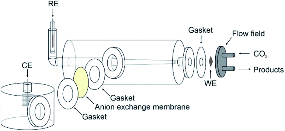 | ||
| Fig. 2 Schematic diagram for the gas diffusion electrode cell used in this work. The glass Luggin capillary effectively minimises the distance between the copper working electrode (WE) and the Ag/AgCl reference electrode (RE). The Pt gauze counter electrode (CE) is separated via an anion exchange membrane. PTFE gaskets are used between all joining parts to help prevent leakage of the electrolyte. The stainless steel flow field features a tight spiral design with a 1.5 mm depth to maximise the interaction of the CO2 with the copper catalyst. | ||
Electrochemical experiments were carried out using an Autolab potentiostat (Metrohm PGSTAT204) with a 10 A current booster. Data were collected using Nova 2.1. Gas samples were collected at regular intervals in 1 L Teldar® gas sampling bags for ex situ gas chromatography (GC) analysis. The GC (Shimadzu GC 2030) was equipped with a Porapak Q 80/100 column with thermal conductivity (CO) and flame ionisation (CH4 and C2H4) detectors. Faradaic efficiencies (% FE) were calculated for each product, defined as the percentage of the charge that was used to produce each given species. For gaseous products, % FE is given by
 | (5) |
Results
The impact of the 1-octadecanethiol on the CO2RR at Cu GDEs was investigated via linear sweep voltammetry (LSV) in 1 M KOH. Here, the GDEs were biased 300 mV negative of OCP, and then swept negatively at 1 mV min−1 until a 200 mA cm−2 cut-off was reached. KOH is used as the high pH and strongly adsorbing OH− ions can hinder hydrogen production via water electrolysis. The presence of the 1-octadecanethiol layer can be seen to shift the reduction wave to more negative potentials (Fig. 3A), implying an increased overpotential required to drive the CO2RR at the thiol-coated electrodes. From this LSV, it is not clear as to whether this shift is due to an impact on the CO2RR kinetics, or the removal of the water reduction current, revealing a LSV solely from the CO2RR at more negative potentials.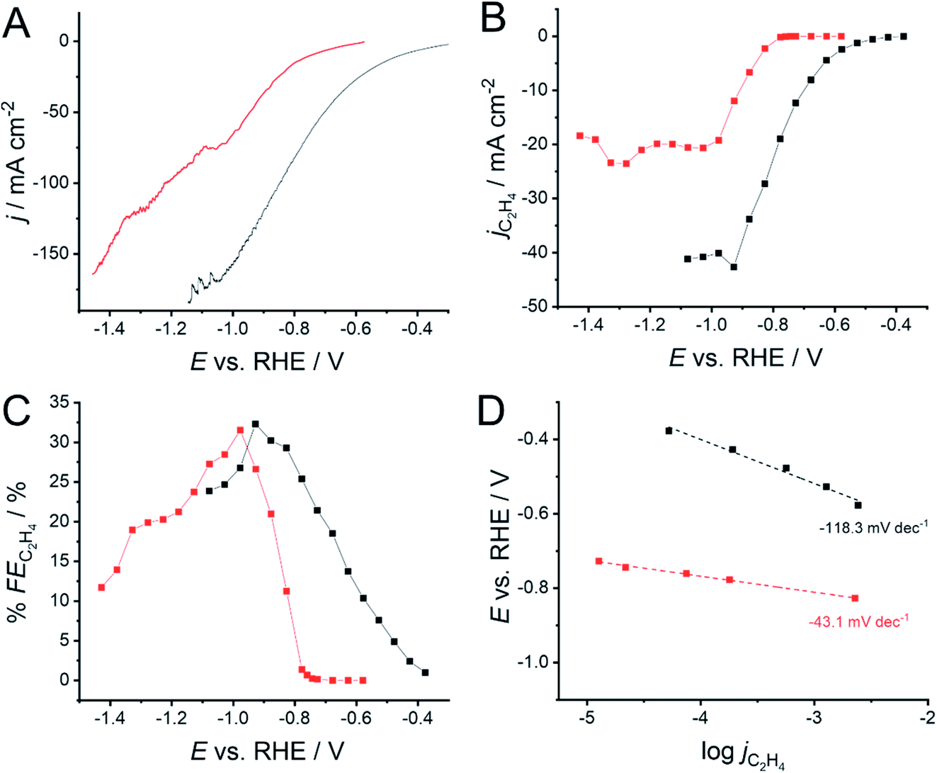 | ||
| Fig. 3 (A) Linear sweep voltammograms (LSVs) for CO2 reduction at a 500 nm Cu GDE electrode in 1 M KOH, recorded with (red) and without (black) a monolayer of 1-octadecanethiol to form a hydrophobic interface. (B) Extracted current densities for CO2 reduction specifically to C2H4 (jC2H4) calculated using eqn (6). (C) Faradaic efficiencies for C2H4 production (% FEC2H4) extracted from the LSVs in (A), calculated using eqn (5). (D) Tafel slopes extracted from the LSVs in (A). Linear fits were performed from the first potential where C2H4 was detected over a range of 200 mV. A shallower gradient indicates that the reaction is kinetically more facile. The connecting lines in (B and C) are intended as a visual guide only. | ||
In order to determine the origin of this potential shift, it is necessary to discuss the impact of the 1-octadecanethiol layer on the rate of CO2RR specifically to C2H4, whereas Fig. 3A shows the cumulative current response for all reduction processes, including CO2 to all possible reduction products and a sizeable contribution from water reduction to H2. To this end, gas samples were taken at regular intervals along the LSV. These were analysed via GC ex situ and the % FE was calculated according to eqn (5). From this, the current density passed specifically due to the reduction of CO2 to C2H4 (jC2H4) can be calculated as a fraction of the total current passed (jtotal)
 | (6) |
The recorded jC2H4 (Fig. 3B) shows the same trend as for jtotal, where the 1-octadecanethiol layer shifts the CO2RR to more negative potentials, as was seen in Fig. 3A. This is important, as this means that the potential shift is due to a change in the process of CO2 reduction to C2H4, and cannot be dismissed as a decrease in the degree of water reduction due to the hydrophobicity of the 1-octadecanethiol layer.
The recorded jC2H4 appears to plateau for both electrodes, suggesting a maximum turnover rate for C2H4 production at both electrodes. This is not seen in the LSVs in Fig. 3A, which is most likely due to an accelerating rate of water reduction at larger overpotentials masking the jC2H4 plateau. The plateau in the presence of the 1-octadecanethiol layer is around half the magnitude of that with the bare electrode, suggesting that the hydrophobic layer is limiting the turnover rate at larger current densities. Since the thiol adsorbs on Cu surface sites on the GDE, it seems likely that the decrease in the jC2H4 plateau is due to catalytic surface sites being blocked.
Although jC2H4 indicates significantly better performance of the bare electrode, the recorded % FE shows a more even performance, with both electrodes presenting a maximum % FE of a little over 30% (Fig. 3C). As with the overall position of the LSV wave, the onset of larger % FE is shifted to more negative potentials. However, the rate of % FE increase as the potential is swept negatively is significantly steeper in the presence of the 1-octadecanethiol layer with respect to the bare Cu GDE. This is confirmed by the sizeable reduction in the Tafel slope from −118.3 to −43.1 mV dec−1 recorded over the same current density range (Fig. 3D).
The presence of the 1-octadecanethiol monolayer on a Cu GDE can be characterised by a muted CO2RR performance at larger current densities, but a sizeable increase in activity towards C2H4 production at lower overpotentials. This trend is clearer when reducing CO2 galvanostatically, where % FE is much higher at a 1-octadecanethiol coated electrode at low current densities. This difference becomes progressively smaller as the magnitude of the current density increases until the GDE is biased at −200 mA cm−2, where the % FE appears to be equal at both electrodes regardless of the surface coating (Fig. 4).
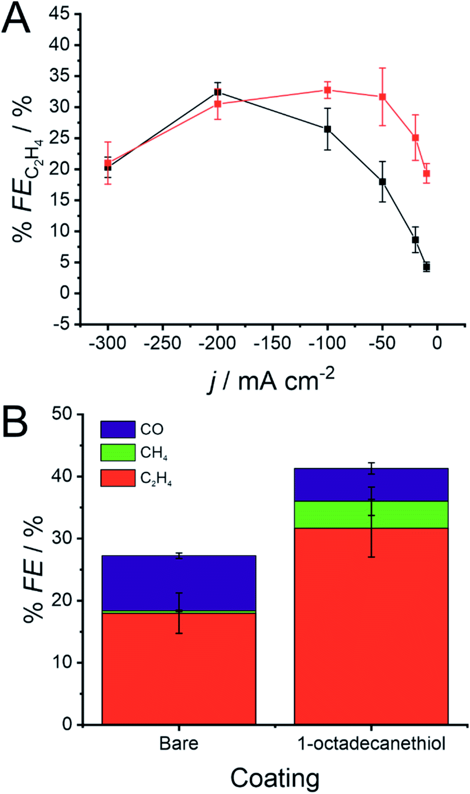 | ||
| Fig. 4 (A) Faradaic efficiency for C2H4 formation (% FEC2H4) during galvanostatic CO2 reduction at a 500 nm Cu GDE in 1 M KOH with (red) and without (black) a monolayer of 1-octadecanethiol to form a hydrophobic interface. (B) % FE for CO, CH4 and C2H4 with and without the 1-octadecanethiol layer during galvanostatic CO2 reduction at −50 mA cm−2 using the same conditions as in (A). Error bars display one standard deviation (n = 3). | ||
Discussion
The 1-octadecanethiol coated Cu GDEs show distinct electrochemical properties versus the uncoated equivalent. The greatly increased C2H4 selectivity at low current densities in contrast with the more similar performance at high current densities suggests a complex reaction environment at the GDE surface during CO2RR. When attempting to rationalise this trend, we see the following possibilities:(i) The 1-octadecanethiol monolayer is blocking pores within the GDE structure. This inhibits gas flow and blocks electrolyte access to Cu particles lower in the catalyst layer.
(ii) The advanced hydrophobicity of the 1-octadecanethiol layer results in a diminished proton supply to the catalyst surface, which becomes a limiting factor to the reaction rate.
(iii) The adsorbed 1-octadecanethiol blocks active sites at the catalyst surface. This will lower the rate of water reduction, which is advantageous, but also lower the rate of the CO2RR, which is deleterious.
(iv) The 1-octadecanethiol coated electrode produces a distinct reaction environment that changes the CO2RR mechanism. The net impact is an improved rate of C2H4 production when the system is under kinetic control.
We consider the first option due to the importance of rapid gas flow to the operations of GDEs in general. Open porous GDEs give a rapid rate of CO2 mass transport in the gas phase, which helps overcome low CO2 solubility in aqueous electrolytes to give a fast rate of reduction. It is conceivable that blocked GDE pores could restrict CO2 flow. This effect would likely have a proportionally larger impact at high current densities, where the low CO2 availability would lead to a greater proportion of the current density driving H2 evolution by water electrolysis.
The second option is related to the overall reaction for C2H4 formation as described in eqn (3). The full mechanism requires a total of 12 proton transfers to come from the electrolyte. There is a clear need for CO2 and its reduction intermediates to interact with the electrolyte, which may be impeded by an overly hydrophobic surface.
The third option is due to water reduction and CO2 reduction both requiring surface adsorption of the starting materials for electron transfers to occur. The observed electrochemical trend would then be a combination of both reactions being hindered to differing extents by the thiol layer.
The fourth option considers that, rather than the thiol specifically hindering CO2RR at larger current densities, the observed trend is due to an enhancement that can only be seen at less negative potentials. As the current density increases, limitations to the CO2 concentration or acceleration of parasitic water reduction outweigh the benefits to the CO2RR kinetics.
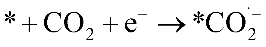
We can gain insights into which is the more likely cause from the clear difference between the Tafel slopes. Small variances in the Tafel slope are a simple means to demonstrate the relative kinetic activity of catalysts towards a certain electrochemical reaction. However, the sizeable difference in the Tafel slope seen here implies that the presence of the 1-octadecanethiol has impacted the rate determining step of the reaction.26 In the case of CO2RR, the rate determining step is usually discussed as the first electron transfer to CO2 to give the adsorbed radical anion 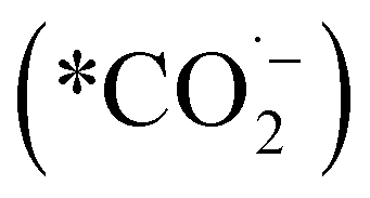
 | (7) |
| *COOH + e− + H+ → *CO + H2O | (8) |
Eqn (8) also highlights a proton dependence in the rate determining step for this route. In this case, the poorer performance at high current densities could be explained by the highly hydrophobic interface and low water availability, causing the proton supply to become a limiting factor in the rate of CO2 reduction.
It seems that the 1-octadecanethiol layer does modify the CO2RR reaction environment as intended. However the requirement for 12 proton transfers to reach C2H4 means that this layer alone is not suited to high current density operations. This presents an opportunity for new catalyst coatings by combining the benefits of the hydrophobic 1-octadecanethiol with a secondary hydrophilic layer capable of supplying protons for C2H4 while preserving the triphasic interface.
This avenue of research would require considerable refinement to the catalyst–electrolyte interface. The supplementary hydrophilic layer must provide the necessary proton supply for the CO2RR mechanism without interfering with the advantages of the hydrophobic thiol layer or blocking gas flow channels within the GDE structure. Conductive ionomers such as those commonly employed in membrane electrode assemblies could be a first point of interest. It would be interesting to see if proton conductive ionomers such as Nafion® could be employed in a neutral carbonate electrolyte without significant acceleration of the hydrogen evolution reaction.
Alternatively, materials that have been previously employed for specific modifications to the CO2RR could be combined with the 1-octadecanethiol layer in order to further enhance the CO2RR. The CO2RR literature contains a broad range of solid polymer electrolytes,28 ionic liquids,29 and polymer coatings30 that have a significant impact on the CO2RR activity and selectivity.
Of course, other factors could also still be influencing the unique electrochemical behaviour alongside this dependence. It is also important to consider how the 1-octadecanethiol layer might impact the mechanistic steps that determine the selectivity towards C2H4. The key step in C2H4 production, as opposed to any of the other CO2RR products, is in the formation of the C–C bond. There are two primary paths that have been proposed for this step. The first is the dimerization between neighbouring *CO species, which is favoured under low overpotential conditions and at Cu(100) facets.31
| *CO + *CO → *COCO | (9) |
The second is the dimerization between *CO and its hydrogenated product *CHO, which is favoured under high overpotential conditions and at Cu(111) facets.32
| *CO + *CHO → *COCHO | (10) |
The key distinction between these two mechanisms is the role of the *CHO intermediate. *CHO is a common intermediate in the CO2RR mechanism for CH4 and C2H4 production. CO2 reduction via the pathway in eqn (9) would therefore be expected to produce C2H4, whereas reduction by eqn (10) would be expected to produce a mixture of CH4 and C2H4. Fig. 4B shows that, at the same current density, the % FE for CH4 increases sizeably from 0.4 ± 0.4% to 4.4 ± 2.3%.
This enhancement in CH4 production suggests that the 1-octadecanethiol favours the *CHO route even at lower current densities, whereas the bare electrode favours the *CO route under the same conditions. This is likely due to the Cu surface experiencing a higher overpotential, as reflected in the shift in the LSV in Fig. 3, which favours the high overpotential *CHO path. This mechanistic dependence would merit revisiting, assuming that the challenge of proton supply to the triphasic interface could be addressed by a secondary hydrophilic layer, as previously discussed.
Conclusions
The addition of a hydrophobic monolayer of 1-octadecanethiol to a standard Cu GDE results in a sizeable change to the CO2RR. The decrease in Tafel slope from −118.3 to −43.1 mV dec−1 points to a shift in the rate determining step. The net impact is a large improvement to the C2H4 generation at low current densities. This appears to be due to the presence of the 1-octadecanethiol facilitating the formation of a triphasic interface within the Cu catalytic layer. At higher current densities, the increased hydrophobicity shows a negative impact by limiting the supply of protons, which hinders the full CO2 reduction to C2H4 as it requires 12 protonation steps.The use of a hydrophobic layer to provide a triphasic interface within a GDE catalytic layer is a promising avenue towards accelerating the CO2RR at GDEs, although clearly more work is needed to advance the concept to industrially relevant standards. The key focus from this point forward should be to compensate for the loss in proton supply while maintaining the advantages that the triphasic interface can provide. This would most likely be through the addition of a secondary hydrophilic layer on top of the hydrophobic 1-octadecanethiol to function as a proton source during CO2RR at the triphasic interface. Significant efforts would be needed to investigate both the ideal material to carry out this role and a means of addition into the catalyst layer to ensure an even dispersion over the hydrophobic layer without hindering the hydrophobic interface or blocking GDE pores or catalytic active sites.
Author contributions
Samuel C. Perry: conceptualization, investigation, methodology, visualization, writing – original draft; Sotirios Mavrikis: investigation, writing – review and editing; Moritz Wegener: resources; Pāvels Nazarovs: resources; Ling Wang: writing – review and editing; Carlos Ponce de León: writing – review and editing.Conflicts of interest
There are no conflicts to declare.Acknowledgements
This work is supported as part of the CO2-based electrosynthesis of ethylene oxide (CO2EXIDE) project, which receives funding from the European Union’s Horizon 2020 research and innovation programme in co-operation with the sustainable process industry through resource and energy efficiency (SPIRE) initiative under grant agreement no. 768789.References
- D. Pletcher, Electrochem. Commun., 2015, 61, 97–101 Search PubMed.
- S. Gao, Y. Lin, X. Jiao, Y. Sun, Q. Luo, W. Zhang, D. Li, J. Yang and Y. Xie, Nature, 2016, 529, 68 Search PubMed.
- M. Liu, Y. Pang, B. Zhang, P. De Luna, O. Voznyy, J. Xu, X. Zheng, C. T. Dinh, F. Fan, C. Cao, F. P. G. de Arquer, T. S. Safaei, A. Mepham, A. Klinkova, E. Kumacheva, T. Filleter, D. Sinton, S. O. Kelley and E. H. Sargent, Nature, 2016, 537, 382 Search PubMed.
- S. Lin, C. S. Diercks, Y.-B. Zhang, N. Kornienko, E. M. Nichols, Y. Zhao, A. R. Paris, D. Kim, P. Yang, O. M. Yaghi and C. J. Chang, Science, 2015, 349, 1208–1213 Search PubMed.
- D. Tan, J. Zhang, X. Cheng, X. Tan, J. Shi, B. Zhang, B. Han, L. Zheng and J. Zhang, Chem. Sci., 2019, 10, 4491–4496 Search PubMed.
- M. Wang, K. Torbensen, D. Salvatore, S. Ren, D. Joulié, F. Dumoulin, D. Mendoza, B. Lassalle-Kaiser, U. Işci, C. P. Berlinguette and M. Robert, Nat. Commun., 2019, 10, 3602 Search PubMed.
- F. Zhang, Z. Jin, C. Chen, Y. Tang, S. A. Mahyoub, S. Yan and Z.-M. Cheng, Ind. Eng. Chem. Res., 2020, 59, 5664–5674 Search PubMed.
- S. C. Perry, S. M. Gateman, R. Malpass-Evans, N. McKeown, M. Wegener, P. Nazarovs, J. Mauzeroll, L. Wang and C. Ponce de León, Chemosphere, 2020, 248, 125993 Search PubMed.
- F. Li, A. Thevenon, A. Rosas-Hernández, Z. Wang, Y. Li, C. M. Gabardo, A. Ozden, C. T. Dinh, J. Li, Y. Wang, J. P. Edwards, Y. Xu, C. McCallum, L. Tao, Z.-Q. Liang, M. Luo, X. Wang, H. Li, C. P. O’Brien, C.-S. Tan, D.-H. Nam, R. Quintero-Bermudez, T.-T. Zhuang, Y. C. Li, Z. Han, R. D. Britt, D. Sinton, T. Agapie, J. C. Peters and E. H. Sargent, Nature, 2020, 577, 509–513 Search PubMed.
- M. G. Kibria, J. P. Edwards, C. M. Gabardo, C.-T. Dinh, A. Seifitokaldani, D. Sinton and E. H. Sargent, Adv. Mater., 2019, 31, 1807166 Search PubMed.
- S. C. Perry, P.-k. Leung, L. Wang and C. Ponce de León, Curr. Opin. Electrochem., 2020, 20, 88–98 Search PubMed.
- L. Fan, C. Xia, F. Yang, J. Wang, H. Wang and Y. Lu, Sci. Adv., 2020, 6, eaay3111 Search PubMed.
- M. Wu, C. Zhu, K. Wang, G. Li, X. Dong, Y. Song, J. Xue, W. Chen, W. Wei and Y. Sun, ACS Appl. Mater. Interfaces, 2020, 12, 11562–11569 Search PubMed.
- Y. Wang, H. Shen, K. J. T. Livi, D. Raciti, H. Zong, J. Gregg, M. Onadeko, Y. Wan, A. Watson and C. Wang, Nano Lett., 2019, 19, 8461–8468 Search PubMed.
- D. Gao, I. Sinev, F. Scholten, R. M. Arán-Ais, N. J. Divins, K. Kvashnina, J. Timoshenko and B. Roldan Cuenya, Angew. Chem., Int. Ed., 2019, 58, 17047–17053 Search PubMed.
- T.-C. Chou, C.-C. Chang, H.-L. Yu, W.-Y. Yu, C.-L. Dong, J.-J. Velasco-Vélez, C.-H. Chuang, L.-C. Chen, J.-F. Lee, J.-M. Chen and H.-L. Wu, J. Am. Chem. Soc., 2020, 142, 2857–2867 Search PubMed.
- L. Shang, X. Lv, H. Shen, Z. Shao and G. Zheng, J. Colloid Interface Sci., 2019, 552, 426–431 Search PubMed.
- C.-T. Dinh, T. Burdyny, M. G. Kibria, A. Seifitokaldani, C. M. Gabardo, F. P. García de Arquer, A. Kiani, J. P. Edwards, P. De Luna, O. S. Bushuyev, C. Zou, R. Quintero-Bermudez, Y. Pang, D. Sinton and E. H. Sargent, Science, 2018, 360, 783–787 Search PubMed.
- F. P. García de Arquer, C.-T. Dinh, A. Ozden, J. Wicks, C. McCallum, A. R. Kirmani, D.-H. Nam, C. Gabardo, A. Seifitokaldani, X. Wang, Y. C. Li, F. Li, J. Edwards, L. J. Richter, S. J. Thorpe, D. Sinton and E. H. Sargent, Science, 2020, 367, 661–666 Search PubMed.
- S. C. Perry, C. Ponce de León and F. C. Walsh, J. Electrochem. Soc., 2020, 167, 155525 Search PubMed.
- K. Ogura, R. Oohara and Y. Kudo, J. Electrochem. Soc., 2005, 152, D213–D219 Search PubMed.
- N. S. Romero Cuellar, K. Wiesner-Fleischer, M. Fleischer, A. Rucki and O. Hinrichsen, Electrochim. Acta, 2019, 307, 164–175 Search PubMed.
- N. T. Nesbitt, T. Burdyny, H. Simonson, D. Salvatore, D. Bohra, R. Kas and W. A. Smith, ACS Catal., 2020, 10, 14093–14106 Search PubMed.
- D. Wakerley, S. Lamaison, F. Ozanam, N. Menguy, D. Mercier, P. Marcus, M. Fontecave and V. Mougel, Nat. Mater., 2019, 18, 1222–1227 Search PubMed.
- M. Jalal Uddin, M. Khalid Hossain, M. I. Hossain, W. Qarony, S. Tayyaba, M. N. H. Mia, M. F. Pervez and S. Hossen, Results Phys., 2017, 7, 2289–2295 Search PubMed.
- T. Shinagawa, A. T. Garcia-Esparza and K. Takanabe, Sci. Rep., 2015, 5, 13801 Search PubMed.
- C. W. Lee, N. H. Cho, S. W. Im, M. S. Jee, Y. J. Hwang, B. K. Min and K. T. Nam, J. Mater. Chem. A, 2018, 6, 14043–14057 Search PubMed.
- L. M. Aeshala, R. G. Uppaluri and A. Verma, J. CO2 Util., 2013, 3–4, 49–55 Search PubMed.
- D. Faggion, W. D. G. Gonçalves and J. Dupont, Front. Chem., 2019, 7, 102 Search PubMed.
- D.-H. Nam, P. De Luna, A. Rosas-Hernández, A. Thevenon, F. Li, T. Agapie, J. C. Peters, O. Shekhah, M. Eddaoudi and E. H. Sargent, Nat. Mater., 2020, 19, 266–276 Search PubMed.
- K. J. P. Schouten, Z. Qin, E. Pérez Gallent and M. T. M. Koper, J. Am. Chem. Soc., 2012, 134, 9864–9867 Search PubMed.
- A. J. Garza, A. T. Bell and M. Head-Gordon, ACS Catal., 2018, 8, 1490–1499 Search PubMed.
| This journal is © The Royal Society of Chemistry 2021 |