
Liquid metals for tuning gas sensitive layers†
Jialuo
Han
a,
Jiong
Yang
a,
Jianbo
Tang
a,
Mohammad B.
Ghasemian
a,
Lee J.
Hubble
b,
Nitu
Syed
c,
Torben
Daeneke
 c and
Kourosh
Kalantar-Zadeh
*a
c and
Kourosh
Kalantar-Zadeh
*a
aSchool of Chemical Engineering, University of New South Wales (UNSW), Sydney, NSW 2052, Australia. E-mail: k.kalantar-zadeh@unsw.edu.au
bCSIRO Manufacturing, Lindfield, NSW 2070, Australia
cSchool of Engineering, RMIT University, Melbourne, VIC 3000, Australia
First published on 23rd April 2019
Abstract
Liquid metals can offer extraordinary properties for application in the field of sensors, yet their potential has not been fully realised. In this work, we present a heterostructure mix of eutectic alloy of gallium and two dimensional (2D) flakes of tungsten oxides (WO3) for gas sensing. We show that the eutectic alloy of EGaIn, made of gallium and indium, can be co-sonicated with acid bath synthesised 2D WO3 for chemisorption sensing of H2 gas molecules. We demonstrate that this co-sonication results in extra trap bands within the bandgap of WO3 to enhance the gas sensing properties. Another interesting observation was the effect on reducing the size of the sonicated EGaIn droplets in the presence of 2D WO3 flakes, which is likely due to the increase of shear force during the sonication. Mixes using different ratios of WO3 and EGaIn were synthesised. The optimum gas sensing operation in terms of response factor was seen in the 70% WO3–30% EGaIn mix. This work provides a viable pathway towards a new platform where liquid metals can be used for sensing applications and they offer advantages to augment the capabilities of sensors.
Introduction
The field of low melting point liquid metals is quickly expanding,1–5 while many properties of liquid metals for sensing applications remain largely unexplored.6,7 Gallium-based liquid metals, including the eutectic alloy of gallium and indium (EGaIn-Ga 75.5% and 24.5% In), form an oxide layer, predominantly gallium oxide, on their surfaces under ambient conditions or after annealing.8–12 This oxide layer establishes a heterostructure with reference to the metallic core and the properties of the oxide/metal core structure can be tuned for specific applications.A sonication process can be applied to achieve high surface-to-volume ratios of EGaIn particles coated with gallium oxide.4,13–16 These particles have been used for different applications such as heavy metal ion sensing,17 heterogeneous catalysis,18 track printing16 and many others.4 Gallium oxide, like many other transition and post-transition metal oxides, exhibits a propensity to chemisorb oxidising and reducing gases at elevated temperatures, modulating the carrier concentration, and presenting an attractive mechanism for gas sensing.19 Although sonicated liquid metal droplets have been studied for gas sensing applications,6 their performance in terms of response and recovery time and also sensitivity, has so far been limited.
One approach to improve the sensing performance of gallium-based liquid metals is to establish ternary heterostructures by incorporating other metal oxides which are known to be suitable for gas sensing such as tungsten oxide.20 These materials show synergetic behaviour towards liquid metals and gallium oxide.
Two-dimensional (2D) tungsten trioxide (WO3) is a stable n-type semiconductor,21 and is a well-studied functional oxide applied in a diverse range of applications, especially in chemical sensors.20,22 It possesses stable thermal and chemical properties, low dimensionality, excellent gas-responsive properties and a large surface area for both chemical and physical interactions.23–25
In this paper, we report on the investigation of the performance of the hydrogen (H2) gas interaction with WO3 nanosheets coated on EGaIn. In these experiments, hydrogen (H2) was chosen as the target gas as it is considered as one of the most promising next-generation energy sources and a clean energy carrier. There is a wide range of H2 gas applications in industrial processes, especially in petroleum, fertilizer and chemical industries, power plants, semiconductor developments and anaerobic bioreactions.26,27 It is necessary to monitor H2 gas concentration at various levels due to its high flammability above 4% in ambient air, low ignition energy of 0.02 mJ and high deflagration index.
In this work, WO3 nanosheets were obtained via a wet chemical sonication procedure in which tungsten powder was used in an acidic solution at a mildly elevated temperature. The fabrication of the gas sensitive layers was achieved by co-sonicating bulk EGaIn in suspensions of WO3 nanosheets with different mass ratios. These ternary heterostructures of WO3–EGaIn were tested for their H2 sensitivity, while studying the response time and recovery time of different ratios of WO3–EGaIn.
Experimental section
Synthesis of 2D WO3 nanosheet coated EGaIn
The 2D WO3 nanosheets were synthesised by an adapted wet chemical and sonication method.21 In this experiment, 300 mg of average 12 μm size tungsten powder (99.9% purity, Sigma-Aldrich) was added into 10 mL of 1.5 mol L−1 nitric acid (69% Sigma-Aldrich reagent, diluted with deionised (DI) water). This solution was sonicated in an ultrasonic bath (Unisonics, FXP10DH, 100 W, 40 kHz) at a constant temperature of 60 °C for at least 6 h. After sonication, 20 mL DI water was added into each sample, which was then centrifuged (Thermoline Centrifuge CR4000) for 10 min at 4000 rpm and the supernatant was collected. The supernatant was dried in an oven at 100 °C followed by an annealing step in a tube furnace at 400 °C for 30 min.Following the synthesis of WO3 nanosheets, WO3 nanosheet/EGaIn mixtures were prepared by sonication in an ultrasonic bath (Unisonics, FXP10DH, 100 W, 40 kHz). Different amounts of WO3 nanosheets were mixed and sonicated with a bulk EGaIn in DI water to obtain various mass ratios of these materials with a final concentration of 20 mg mL−1. Sonication was conducted for 2 h in order to breakdown the EGaIn bulk droplets into smaller particles, which were coated with WO3 nanosheets at the same time. Later, the sonicated solution was dried in an oven at 100 °C and annealed again in the tube furnace at 400 °C for 30 min to obtain solid powder for the sensor fabrication.
Characterisation of the WO3 nanosheet coated EGaIn
Transmission electron microscopy (TEM, Phillip CM200) was utilised to study the morphology of synthesised materials. The lattice parameters of the unannealed and annealed WO3 nanosheets were investigated by high-resolution TEM (HRTEM) and selected area electron diffraction (SAED) analyses. The samples were diluted in absolute ethanol to a suitable concentration, drop-cast and dried at room temperature onto holey Cu-carbon grids (Ted-Pella, USA) for TEM characterisation. Scanning electron microscopy (SEM) images were taken on silicon wafers using an FEI Nova NanoSEM 450. The Raman spectra of the samples deposited on electrodes were obtained at a laser excitation wavelength of 532 nm(Raman Microscope, Renishaw inVia 2). X-ray diffraction (XRD) patterns were obtained using an MPD Xpert Multipurpose XRD. X-ray photoelectron spectrometry (XPS, Thermo Scientific K-alpha XPS spectrometer) and valence band analysis were conducted using a monochromatic AI kα source (hv = 1486 eV) and the samples were deposited on conductive tapes. The optical absorption spectra were obtained using an ultraviolet-visible spectrometer (UV-Vis, Agilent Cary5000) with baseline correction. The samples were prepared by diluting annealed powder in absolute ethanol at a concentration of 40 mg mL−1 and drop-cast on clean quartz glasses. The results of the UV-Vis spectra were employed for calculating Tauc plots to determine the optical band gaps. Moreover, to further examine the band structure of our materials, a standard three electrode set-up was utilised to perform Mott–Schottky measurements. It was controlled by a CHI650E (CHI Instrument Co.) electrochemical workstation. The cell set-up included a working electrode that was 1 cm × 1 cm carbon tape coated with the samples, an Ag/AgCl (in 3 M NaCl, aq.) reference electrode, a Pt counter electrode, and Na2SO4 solution as the electrolyte (0.3 mol L−1, pH ca. 7.0). EAg/AgCl = −4.669 V vs. Vac is used for converting to the vacuum scale, which is computed using the equation Eabs = ESHE + 4.44 ± 0.02 V, in which Eabs is the absolute potential and ESHE denotes the electrode potential relative to the standard hydrogen electrode. The measurements were carried out with a sinusoidal signal at an amplitude of 5 mV and a frequency of 500 Hz.28 The electrolyte was degassed by purging nitrogen before the experiment.Gas-sensor fabrication and test set-up
Gas sensors were fabricated by drop-casting only 2D WO3 (as the first reference), EGaIn coated with WO3 nanosheets, and only EGaIn (as the second reference) onto cleaned alumina ceramic substrates with silver–palladium (Ag–Pd) electrodes with a 0.2 mm spacing between each pair, which were purchased from Beijing Elite Co., Ltd. Twenty microliters of 40 mg mL−1 concentration 400 °C annealed WO3 nanosheet coated EGaIn were drop-cast onto an interdigital electrode positioned on a hotplate at 40 °C. The gas sensors were tested in a LINKAM gas chamber (LINKAM HFS600E-PB4) with a temperature controller (of up to 600 °C). Two channel mass flow controllers (MKS GE50A) were programmed to regulate the gas input at a constant flow rate of 200 sccm and control the concentration of the input gas balanced with synthetic air. The resistance of the gas sensor was measured and recorded using a Siglent SDM3065X multimeter and LabView software. Various temperatures (350 °C, 375 °C, 400 °C, 425 °C and 450 °C) were tested at a fixed concentration of 0.4% H2 gas to obtain the optimal operating temperature. At the said temperature, different ratios of WO3 and EGaIn sensors were investigated at the optimal temperature and various H2 gas concentrations (0.4%, 0.8%, 1.2%, 1.6%, and 2.0%) to explore the optimal response parameters.Results and discussion
Material characterisation
The 2D WO3 nanosheets were synthesised via a wet chemical synthesis process using a W powder source as described in the Experimental section. The air-dried synthesised powder showed a yellow-green colour which turned to olive drab after annealing at 400 °C. This change of colour possibly indicates the presence of oxygen vacancies and dehydration.29The TEM images of unannealed and 400 °C annealed nanosheets are shown in Fig. 1. The TEM micrographs showed that the sheets were rectangular and flat with typical dimensions of 50 to 60 nm. The hydrated sheets exhibited 0.7 nm steps, which are associated with the van der Waals spacings between the planes.21 From the HRTEM, the as synthesised sample seems to be polycrystalline of various domains with a d-spacing of 0.39 nm before annealing. This d-spacing can be assigned to the (200) plane of the orthorhombic tungsten oxide hydrate (WO3·H2O). The WO3 sample annealed at 400 °C shows a d-spacing of 0.38 nm, corresponding to the (020) plane of orthorhombic tungsten oxide.20
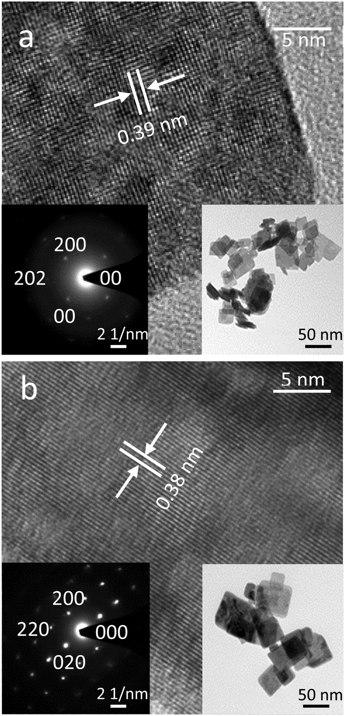 | ||
| Fig. 1 Morphological characterisation of the WO3 nanosheet samples using TEM: including lattice fringe patterns and SAED of (a) unannealed WO3 nanosheet, (b) WO3 nanosheet annealed at 400 °C. | ||
The formation of WO3–EGaIn mixes is described in the Experimental section. Briefly, they were obtained via sonicating a bulk EGaIn droplet in the WO3 nanosheet suspension at different concentrations in DI water for 2 h. The WO3/EGaIn ratios were 100% WO3–0% EGaIn (WO3 only), 30% WO3–70% EGaIn, 50% WO3–50%, 70% WO3–30% EGaIn and 0% WO3–100% EGaIn (only EGaIn) by weight.
During the sonication step, an EGaIn bulk droplet splits into micro and nano-sized spherical or quasi-spherical liquid metal droplets, with the WO3 nanosheets from the homogenised colloidal suspensions having been coated onto their surface.
The surface and cross-sectional SEM and EDX images (Fig. 2) show the adhesion of WO3 flakes on the EGaIn particles, and how the EGaIn droplets are embedded within the WO3 flakes. EDX revealed the location of the EGaIn droplets in the cross-sectional images, with the EGaIn droplets being associated with a reduced concentration of W. The visible surface oxidation of the droplets is mostly associated with the formation of gallium oxides as has been previously demonstrated.14
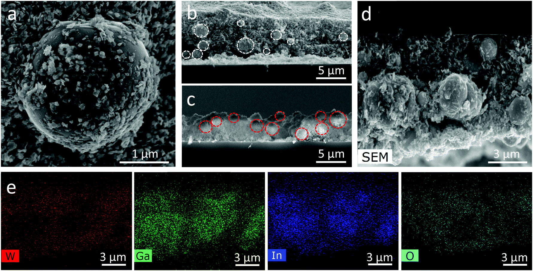 | ||
| Fig. 2 (a) The SEM image of the 70% WO3–30% EGaIn sample. (b and c) The cross-section SEM images of 70% WO3–30% EGaIn and of 30% WO3–70% EGaIn samples, respectively. (d) Bright field EDX image of the 70% WO3–30% EGaIn sample and (e) its elemental mappings. | ||
The cross sections of 70% WO3–30% EGaIn and 30% WO3–70% EGaIn are shown in Fig. 2b and c, respectively. Interestingly, the size of the EGaIn particles decreases from an average of 2.51 μm in 30% WO3–70% EGaIn to an average of 1.50 μm in 70% WO3–30% EGaIn. Fig. S1 and S2 (ESI†) show the comparison of the particle size of three samples of different ratios, and the statistical distribution, average particle sizes, standard deviations are represented. The particle size is repeatable, and the statistics of three 70% WO3–30% EGaIn samples are shown in Fig. S3 and S4 (ESI†). This is because the WO3 nanosheets were involved in the sonication with the EGaIn bulk and they applied extra shear forces on the EGaIn bulk and droplets, hence breaking the aggregates acting as sharp blades during the sonication process.30,31 Their increased concentration could enhance the sonication efficiency by breaking up the EGaIn bulk into smaller particles. In addition, the coverage of WO3 nanosheets, like a protective film, on the surface of EGaIn was higher in the ratio of 70% WO3–30% EGaIn compared with that of the other samples. In this case, the EGaIn particles could likely be distributed with less agglomeration, because they were encapsulated by WO3 nanosheets.30
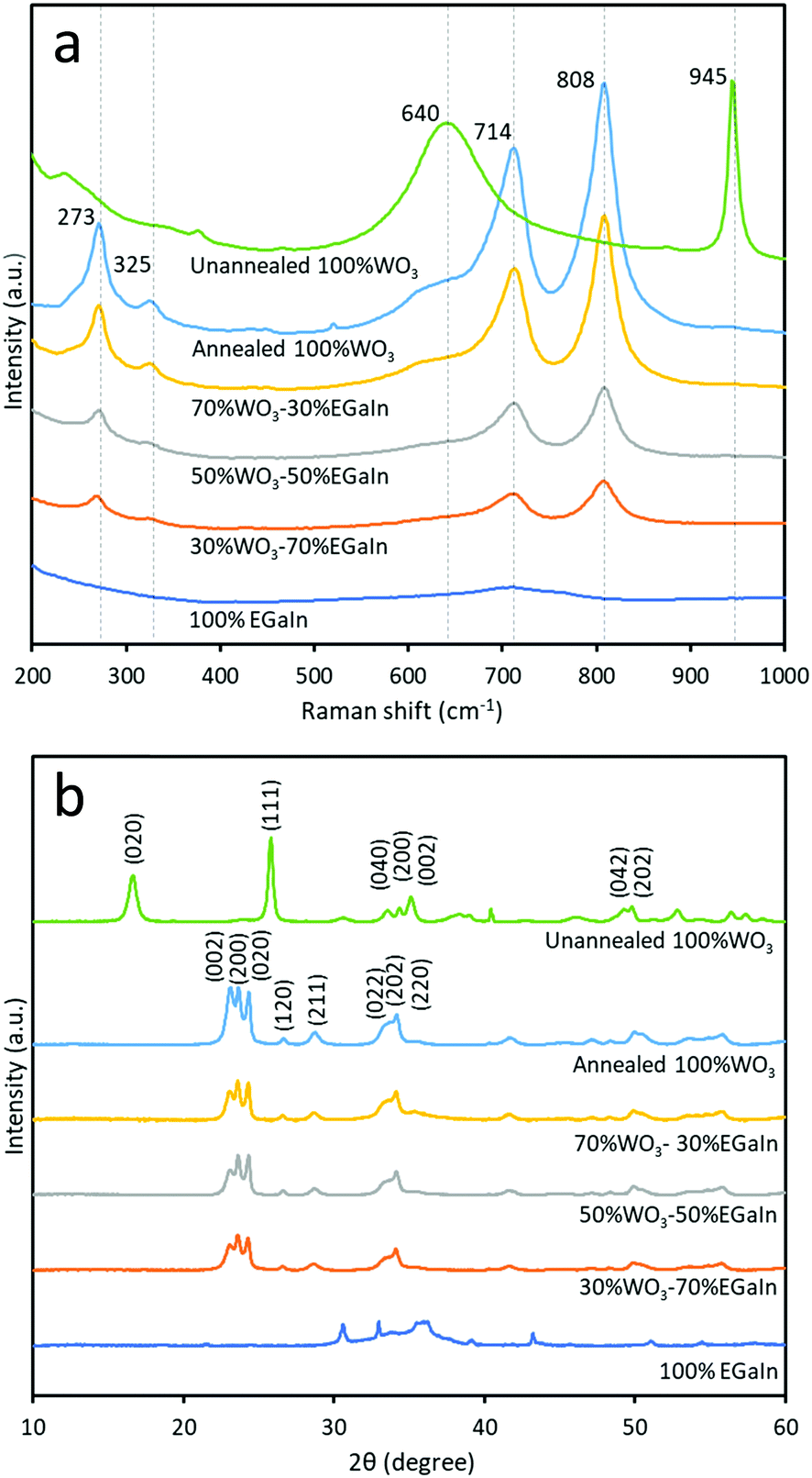
The Raman spectra of the samples prepared at different ratios of WO3 and EGaIn, annealed at 400 °C, are shown in Fig. 3a. For the unannealed, hydrous WO3·H2O sample the peak at ∼945 cm−1 is associated with the symmetric stretching mode of the terminal W6+![[double bond, length as m-dash]](https://www.rsc.org/images/entities/char_e001.gif) O bond. The peak at ∼640 arises due to bridging oxygen sites across planes. This peak is highly influenced by hydration, evidencing the formation of hydrated WO3.32 For the 400 °C annealed sample, the peaks at ∼714 cm−1 and ∼808 cm−1, and the peaks at ∼273 cm−1 and ∼325 cm−1 are due to the stretching vibrations (ν(O–W–O)) and deformation vibrations (δ(O–W–O)), respectively.33,34 A broad peak at ∼727 cm−1 is observed for 100% EGaIn, which is consistent with previous reports6,14 and is mostly associated with gallium oxides. As the EGaIn droplets are embedded in the films of WO3 nanosheets, the Raman signatures of EGaIn are mostly faded in the mixes.
O bond. The peak at ∼640 arises due to bridging oxygen sites across planes. This peak is highly influenced by hydration, evidencing the formation of hydrated WO3.32 For the 400 °C annealed sample, the peaks at ∼714 cm−1 and ∼808 cm−1, and the peaks at ∼273 cm−1 and ∼325 cm−1 are due to the stretching vibrations (ν(O–W–O)) and deformation vibrations (δ(O–W–O)), respectively.33,34 A broad peak at ∼727 cm−1 is observed for 100% EGaIn, which is consistent with previous reports6,14 and is mostly associated with gallium oxides. As the EGaIn droplets are embedded in the films of WO3 nanosheets, the Raman signatures of EGaIn are mostly faded in the mixes.
 | ||
| Fig. 3 Compositional characterisations of the samples: (a) Raman spectroscopy and (b) XRD patterns. | ||
XRD analysis was implemented for the six samples to determine the crystal structure by phase identification, as shown in Fig. 3b. The unannealed sample is a hydrated compound and the dominant peaks match with those of orthorhombic tungsten oxide hydrate WO3·H2O (PDF 43-0679 with lattice parameters a = 5.238 Å, b = 10.704 Å, c = 5.120 Å and lattice angle β = 90°). The annealed WO3 can be matched with orthorhombic WO3 (PDF 07-0880 with lattice parameters a = 7.341 Å, b = 7.570 Å, c = 7.754 Å and lattice angle β = 90°). The three dominant peaks are matched to the planes of (002), (020) and (200). The XRD result for 100% EGaIn is consistent with a previous report that did not show the presence of any crystalline phases, which indicates the amorphous oxide.6,20 From the XRD diffractograms, the 002 peak intensity is decreased relative to the 020 and 200 peak intensities, when increasing the ratio of EGaIn. This can be due to the effect of embedding EGaIn droplets, on which the WO3 flakes are placed and undergo slight reorientation.
The Mott–Schottky measurements provide the flat band potential for each of the samples providing an estimation of their Fermi levels within the electrolyte environment. The flat band potential of EGaIn (Fig. S5, ESI,† and Table 1) is in agreement with previous results.29 The Fermi level can be derived from EFermi = EAg/AgCl – EFlat band, where EAg/AgCl is the reference electrode potential with respect to vacuum, and EFlat band is the measured flat band potential. The Mott–Schottky measurements for different samples are shown in Fig. S5, ESI.†
| Material | UV-Visible (eV) | XPS valence (eV) | Mott–Schottky (V) |
|---|---|---|---|
| 100% WO3 | 2.91 | 2.58 | −2.07 |
| 70% WO3–30% EGaIn | 2.96 | 2.58 | −1.70 |
| 50% WO3–50% EGaIn | 3.00 | 2.78 | −1.50 |
| 30% WO3–70% EGaIn | 3.05 | 2.88 | −1.35 |
| 100% EGaIn | 4.15 | 3.00 | −1.00 |
Valence band spectral analysis was conducted by using XPS. The spectra show the presence of trap states in the mixed samples (Fig. 4a), and the obtained values from the plots yield an energy difference between the Fermi level and the valence band minimum. As can be seen, both EGaIn and WO3 show minimal trap states before mixing, while after mixing the concentration of these trap states is increased dramatically. The largest concentration of the trap states is for 70% WO3–30% EGaIn within the bandgap. It seems that at this ratio the materials show more efficiency in absorbing the sonication energy to reduce the oxide entities under the process.
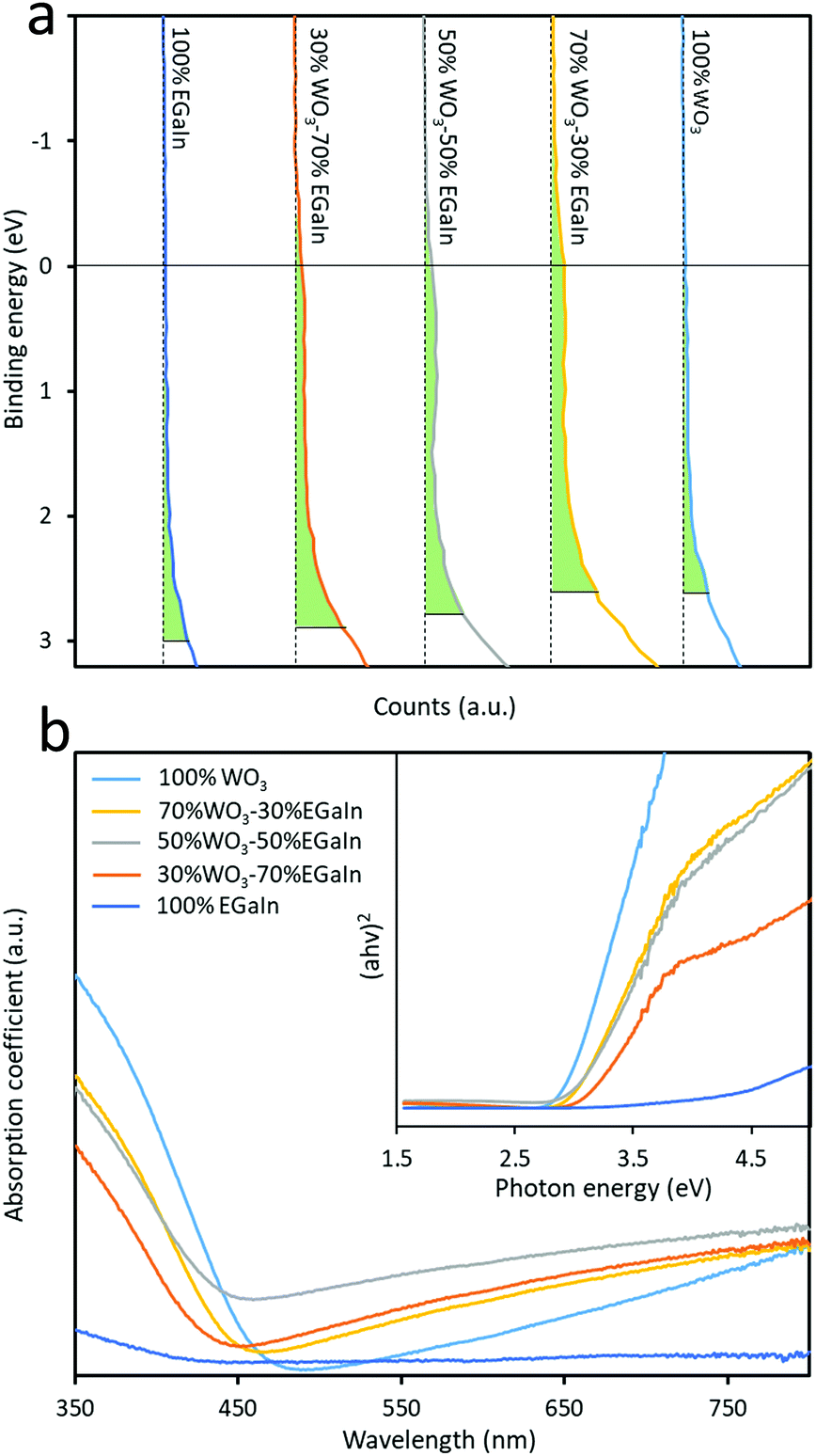 | ||
| Fig. 4 (a) XPS valence band spectra of the five samples and (b) UV-visible absorbance spectra of samples. | ||
The characterisation of the UV-Vis spectra was performed and UV-Vis spectroscopy was performed to assess the optical bandgap applying Tauc analysis, using the  model for a direct transition, in which a is the absorption coefficient, h is the Planck constant, ν is the photon frequency, A is a constant, Eg is the optical energy bandgap. The optical bandgap Eg can be derived from a linear fitting in the plot of the square of the product between the absorption coefficient a and the photon energy hν vs. the photon energy hν for a direct band gap. As can be seen in the Tauc plot (Fig. 4b and Table 1), the bandgap of the sonicated EGaIn is 4.15 eV. The band gap decreases upon increasing the WO3 concentration within the mix, reaching 2.91 eV for the synthesised WO3, which is the typical value.24
The electronic structures of WO3 only, WO3–EGaIn mixtures and EGaIn are shown in Table 1. These electronic structures are also reconstructed in Fig. 5.
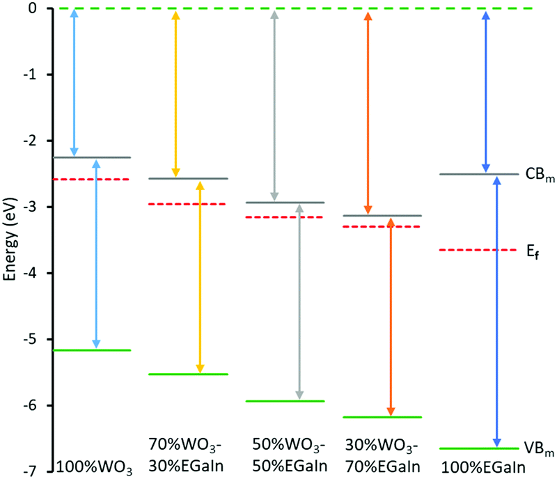 | ||
| Fig. 5 Assessed electronic band structure of the samples with different ratios of WO3 coated EGaIn, utilising values obtained from UV-visible spectroscopy, Mott–Schottky measurements and XPS valence band spectroscopy. | ||
XPS was employed to analyse the stoichiometry and chemical bonding states of different ratios of WO3 to EGaIn (Fig. 6). The W4f orbital peaks at ∼35.7 and ∼37.9 eV are assigned to W4f7/2 and W4f5/2, respectively. The two peaks are consistently seen in all samples, except for the 0% WO3–100% EGaIn sample. The small peak at ∼41.5 eV is assigned to W5p. The peak observed at 22.8 eV can be attributed to the O2s peak. As can be seen, this peak gradually decreases when more EGaIn is added, which is associated with the decreased dominance of WO3. The peaks at binding energies of 18.48 and 20.68 eV correspond to the Ga3d orbital, allowing the resolution of the metallic gallium (Ga0) and the oxidised (Ga3+) states, respectively, when EGaIn is incorporated. It can also be observed that the gallium oxide peak is comparatively stronger in the Ga3d region when more EGaIn is incorporated. It is possible that the presence of more protective WO3 coating, when the WO3 concentration is increased, prevents the surface of EGaIn from full oxidation, but when the ratio of WO3 decreases, the EGaIn particles are more oxidised.35
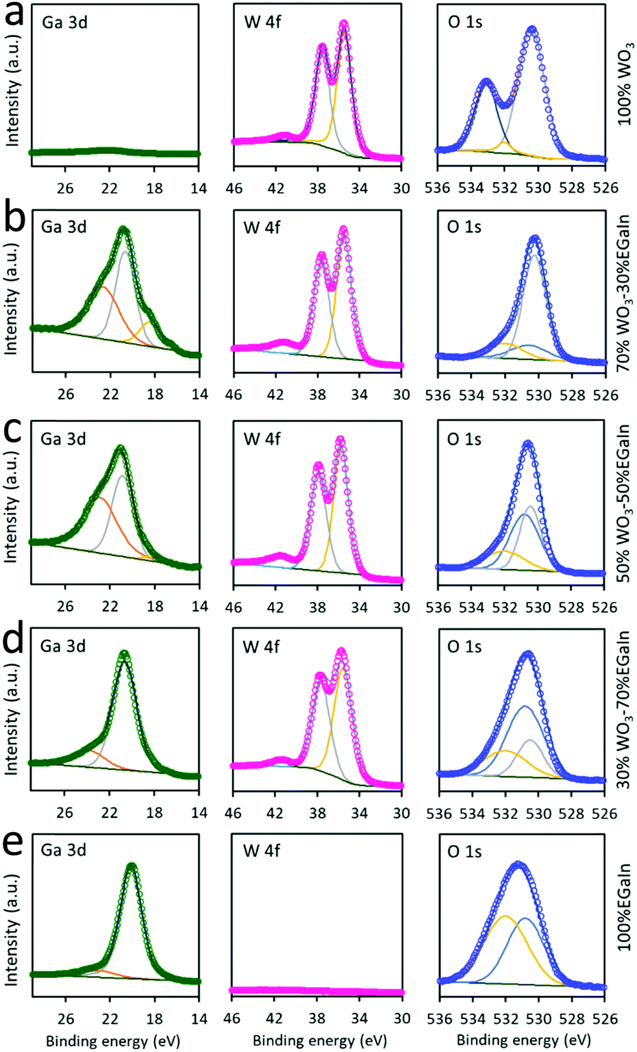 | ||
| Fig. 6 XPS spectra of the 70% WO3 coated 30% EGaIn for (a)100% WO3, (b) 70% WO3–30% EGaIn, (c) 50% WO3–50% EGaIn (d) 30% WO3–70% EGaIn (e) 100% EGaIn. | ||
The O1s peak of 100% WO3 at 530.5 eV is associated with the oxygen bond in WO3, and the peak at ∼533.2 eV shows the oxygen atoms of the surface absorbed ambient H2O molecules, which is consistent with previous studies.20,36 However, the peak at ∼533.2 eV does not appear in the samples with the addition of EGaIn, because the presence of gallium provides a base for the removal of water molecules as the addition of a pool of electrons within the layer repels the water molecules by discouraging hydrogen bonds.37
When more EGaIn is added to the ratio, the ∼530.5 eV peak gradually shifts to ∼530.8 eV which is attributed to the existence of gallium oxide and the reduction of WO3. It is explained that the intensity of gallium oxide peaks are increased and those of WO3 are decreased. The oxygen peak at 532.2 eV is due to the presence of ethanol for mixing EGaIn that increases proportionally with the increase of EGaIn droplet concentrations. As shown in Fig. S6, ESI,† the In3d core level spectra, with two peaks at 444.18 (In3d5/2) and 451.28 eV (In3d3/2), correspond to the In3d orbitals for metallic indium (In0).
Gas sensing characterisations
Gas sensors were fabricated by drop-casting different ratios of WO3 nanosheet coated EGaIn samples (100% WO3, 70% WO3–30% EGaIn, 50% WO3–50% EGaIn, 30% WO3–70% EGaIn, and 100% EGaIn) onto interdigitated transducer substrates. These substrates consisted of Ag–Pd electrode fingers printed on an alumina substrate as described in the Experimental section.During the gas sensing experiment, the electrical resistance was measured for calculating the gas response factor as Ra/Rg in which Rg is defined as the resistance of the gas sensor tested under the investigated gas and Ra is the resistance of the device in synthetic air. The response time and recovery time were studied as the 90% change from the baseline to saturation and back to baseline, respectively.
The determination of the optimal operating temperature was critical in this experiment, which is shown in Fig. 7a (the dynamic test experiments are shown in Fig. S7, ESI†). We tested the sensor made of 70% WO3–30% EGaIn at operating temperatures from 350 °C to 450 °C at 25 °C gaps in 0.4% H2 gas in synthetic air to obtain the response factor, response time and recovery time. It is known that at this temperature range both tungsten and gallium oxide responses to H2 gas are due to chemisorption of H2 gas molecules onto the surface of these oxides.19,38 Considering these three parameters, the sensor made using the 70% WO3–30% EGaIn sample showed the fastest response and recovery time at 400 °C which were 34% and 20% shorter than that at 375 °C, respectively, and the response factor was only 11% lower. In addition, the response time was the same and the recovery time was 70 s shorter than that of 425 °C, while the response factor was 10% lower. Thus, according to the response and recovery time, 400 °C was deemed as the optimal temperature for this experiment.
 | ||
| Fig. 7 (a) Response factor, response time and recovery time of 70% WO3–30% EGaIn at different temperatures, (b) response factors of the samples at different concentrations of H2 gas for different ratios of WO3 and EGaIn, (c) 70% WO3–30% EGaIn repeatability test for different concentration of H2 gas, and (d) dynamic tests of samples at a concentration of 2.0% H2 gas. | ||
Sensors made of samples using different ratios of WO3 and EGaIn were tested at an optimal temperature of 400 °C at different concentrations of H2 ranging from 0.4% to 2.0% balanced in synthetic air. From Fig. 7b, the response factor of 70% WO3–30% EGaIn was significantly increased from ∼14.6 to ∼33.2 in response to 0.4% H2 gas. However, the response factor decreases to ∼3.9 and ∼1.2 for 50% WO3–50% and 30% WO3–70% EGaIn, respectively. Comparing the responses of other H2 gas concentrations, 70% WO3–30% EGaIn showed the largest response factors.
The repeatability of 70% WO3–30% EGaIn is shown in Fig. 7c, the H2 gas concentration was gradually increased during the test. Excellent reversibility was observed for all H2 gas concentrations tested. The selectivity tests of the 70% WO3–30% EGaIn sample was conducted to assess its performance toward H2S and NO2 gases at 400 °C (Fig. S8, ESI†). It shows response factors of 1.8 and 2.5 to 5.2 ppm and 10.3 ppm H2S gas, respectively, and the response factors to 3.6 ppm and 5.4 ppm NO2 are 4.4 and 5.5, respectively. For comparison, Table S1 shows the response factors of 70% WO3–30%EGaIn to different gases, and the resistance trends are also indicated when exposed to the specific gas. The concentration chosen for selectivity measurement is according to the industrial exposure requirements.39,40 The tests show that the sensor is much more selective to H2 in comparison to H2S and NO2. Obviously, for a full selectivity assessment, a larger number of gas species should be tested. Fig. 7d shows the dynamic response of different samples to 2.0% H2 gas, for which 70% WO3–30% EGaIn has the largest response factor.
The sensing mechanism can be explained as the chemisorption of H2 onto the surfaces of the samples. As WO3 nanosheets and gallium oxides are n-type semiconductors of various carrier concentrations a heterostructure is formed at their contacts.20,41 H2 bond is broken down on the surface of the heterostructure and make the absorbed protons that donate electrons to the surface. With more broken H2 bonds on the surface, the number of free electrons donated due to this charge transfer mechanism is increased, and as such the resistance decreases explaining the sensor behaviour in response to the H2 gas.
With reference to WO3, the enhancement in the response factor of all samples with incorporated EGaIn can be associated with the formation of trap states within the bandgap by co-sonication with EGaIn. As shown in the XPS valence band assessment, the trap states increased in intensity within the valence band and this increase is extended across the bandgap.
The additional enhancement for the 70% WO3–30% EGaIn sample can be attributed to the smaller size of the EGaIn particles in comparison to other samples, as presented by the electron microscopy assessments. The smaller particles could enhance the surface-to-volume ratio, which resulted in an increase in the sensitive layer overall interaction with H2 gas molecules.
Overall, the incorporation of the EGaIn particles had a significant impact on tuning the sensor response parameters of the gas sensitive films.
Conclusions
We successfully developed a tuneable sensor for sensing H2 gas by incorporating certain ratios of EGaIn micro/nanodroplets and 2D WO3 nanosheets. The sensors exhibited high sensitivities, as well as, short response and recovery times to H2 due to the formation of trap states across the bandgap. The optimum gas sensing was achieved by 70% WO3–30% EGaIn, in which the size of the EGaIn particles is significantly smaller compared to those of the samples with lower ratios of WO3 nanosheets. This resulted in a larger surface-to-volume ratio, and consequently, a remarkably enhanced interactive surface area with H2. Gas sensing analysis showed that sensors consisting of 70% WO3–30% EGaIn showed optimal performance with a considerable response factor of ∼33.2 at a concentration of 0.4% H2. This sensor configuration also showed superior dynamic performance with excellent reversibility in different gas concentrations in comparison to other WO3 and EGaIn ratios.Due to its unique ternary heterostructure nature, the incorporation of EGaIn particles into gas sensitive films is considered as a new horizon to tune gas sensing materials. The method, presented here, provides a proof-of-concept that such heterostructures with liquid metal droplets can be further explored for engineering of future smart materials for sensing applications.
Conflicts of interest
The authors have no conflicts of interest to declare.Acknowledgements
The authors would like to acknowledge the Australian Research Council (ARC) Laureate Fellowship grant (FL180100053) and the ARC Center of Excellence FLEET (CE170100039) for the financial coverage of this work.References
- L. Jing and Y. Liting, Liquid Metal Biomaterials, Springer, Singapore, 1 edn, 2018 Search PubMed.
- H. Ge, H. Li, S. Mei and J. Liu, Renewable Sustainable Energy Rev., 2013, 21, 331–346 CrossRef CAS.
- L. Sheng, J. Zhang and J. Liu, Adv. Mater., 2014, 26, 6036–6042 CrossRef CAS PubMed.
- N. Kazem, T. Hellebrekers and C. Majidi, Adv. Mater., 2017, 29, 1605985 CrossRef PubMed.
- C. Pan, K. Kumar, J. Li, E. J. Markvicka, P. R. Herman and C. Majidi, Adv. Mater., 2018, 30, 1706937 CrossRef PubMed.
- M. Shafiei, F. Hoshyargar, N. Motta and A. P. O'Mullane, Mater. Des., 2017, 122, 288–295 CrossRef CAS.
- W. Zhang, N. Srichan, A. F. Chrimes, M. Taylor, K. J. Berean, J. Z. Ou, T. Daeneke, A. P. O’Mullane, G. Bryant and K. Kalantar-zadeh, Sens. Actuators, B, 2016, 223, 52–58 CrossRef CAS.
- T. Daeneke, K. Khoshmanesh, N. Mahmood, I. A. de Castro, D. Esrafilzadeh, S. J. Barrow, M. D. Dickey and K. Kalantar-zadeh, Chem. Soc. Rev., 2018, 47, 4073–4111 RSC.
- M. D. Dickey, ACS Appl. Mater. Interfaces, 2014, 6, 18369–18379 CrossRef CAS PubMed.
- G. Bo, L. Ren, X. Xu, Y. Du and S. Dou, Adv. Phys.: X, 2018, 3, 1446359 Search PubMed.
- A. Zavabeti, J. Z. Ou, B. J. Carey, N. Syed, R. Orrell-Trigg, E. L. H. Mayes, C. Xu, O. Kavehei, A. P. O’Mullane, R. B. Kaner, K. Kalantar-zadeh and T. Daeneke, Science, 2017, 358, 332 CrossRef CAS PubMed.
- B. J. Carey, J. Z. Ou, R. M. Clark, K. J. Berean, A. Zavabeti, A. S. R. Chesman, S. P. Russo, D. W. M. Lau, Z.-Q. Xu, Q. Bao, O. Kavehei, B. C. Gibson, M. D. Dickey, R. B. Kaner, T. Daeneke and K. Kalantar-Zadeh, Nat. Commun., 2017, 8, 14482 CrossRef CAS PubMed.
- N. Syed, A. Zavabeti, M. Mohiuddin, B. Zhang, Y. Wang, R. S. Datta, P. Atkin, B. J. Carey, C. Tan, J. van Embden, A. S. R. Chesman, J. Z. Ou, T. Daeneke and K. Kalantar-zadeh, Adv. Funct. Mater., 2017, 27, 1702295 CrossRef.
- W. Zhang, J. Z. Ou, S.-Y. Tang, V. Sivan, D. D. Yao, K. Latham, K. Khoshmanesh, A. Mitchell, A. P. O'Mullane and K. Kalantar-zadeh, Adv. Funct. Mater., 2014, 24, 3799–3807 CrossRef CAS.
- J. N. Hohman, M. Kim, G. A. Wadsworth, H. R. Bednar, J. Jiang, M. A. LeThai and P. S. Weiss, Nano Lett., 2011, 11, 5104–5110 CrossRef CAS PubMed.
- J. W. Boley, E. L. White, G. T. C. Chiu and R. K. Kramer, Adv. Funct. Mater., 2014, 24, 3501–3507 CrossRef CAS.
- V. Sivan, S.-Y. Tang, A. P. O'Mullane, P. Petersen, N. Eshtiaghi, K. Kalantar-zadeh and A. Mitchell, Adv. Funct. Mater., 2013, 23, 144–152 CrossRef CAS.
- F. Hoshyargar, H. Khan, K. Kalantar-zadeh and A. P. O'Mullane, Chem. Commun., 2015, 51, 14026–14029 RSC.
- Y. Li, A. Trinchi, W. Wlodarski, K. Galatsis and K. Kalantar-zadeh, Sens. Actuators, B, 2003, 93, 431–434 CrossRef CAS.
- H. Khan, A. Zavabeti, Y. Wang, C. J. Harrison, B. J. Carey, M. Mohiuddin, A. F. Chrimes, I. A. De Castro, B. Y. Zhang, Y. M. Sabri, S. K. Bhargava, J. Z. Ou, T. Daeneke, S. P. Russo, Y. Li and K. Kalantar-zadeh, Nanoscale, 2017, 9, 19162–19175 RSC.
- K. Kalantar-zadeh, A. Vijayaraghavan, M.-H. Ham, H. Zheng, M. Breedon and M. S. Strano, Chem. Mater., 2010, 22, 5660–5666 CrossRef CAS.
- M. Breedon, P. Spizzirri, M. Taylor, J. du Plessis, D. McCulloch, J. Zhu, L. Yu, Z. Hu, C. Rix, W. Wlodarski and K. Kalantar-zadeh, Cryst. Growth Des., 2010, 10, 430–439 CrossRef CAS.
- Z. Wang, M. Hu, Y. Wei, J. Liu and Y. Qin, Appl. Surf. Sci., 2016, 362, 525–531 CrossRef CAS.
- H. Zheng, J. Z. Ou, M. S. Strano, R. B. Kaner, A. Mitchell and K. Kalantar-zadeh, Adv. Funct. Mater., 2011, 21, 2175–2196 CrossRef CAS.
- M. Shafiei, A. Z. Sadek, J. Yu, K. Latham, M. Breedon, D. McCulloch, K. Kalantar-zadeh and W. Wlodarski, Sens. Lett., 2011, 9, 11–15 CrossRef CAS.
- F. De Schutter, J. Vangrunderbeek, J. Luyten, I. Kosacki, R. Van Landschoot, J. Schram and J. Schoonman, Solid State Ionics, 1992, 57, 77–81 CrossRef CAS.
- T. Hübert, L. Boon-Brett, G. Black and U. Banach, Sens. Actuators, B, 2011, 157, 329–352 CrossRef.
- K. Gelderman, L. Lee and S. W. Donne, J. Chem. Educ., 2007, 84, 685 CrossRef CAS.
- W. Zhang, B. S. Naidu, J. Z. Ou, A. P. O’Mullane, A. F. Chrimes, B. J. Carey, Y. Wang, S.-Y. Tang, V. Sivan, A. Mitchell, S. K. Bhargava and K. Kalantar-zadeh, ACS Appl. Mater. Interfaces, 2015, 7, 1943–1948 CrossRef CAS PubMed.
- B. A. Kheireddin, W. Lu, I. C. Chen and M. Akbulut, Wear, 2013, 303, 185–190 CrossRef CAS.
- Y. Y. Huang and E. M. Terentjev, Polymers, 2012, 4, 275–295 CrossRef.
- M. P. Thi and G. Velasco, Solid State Ionics, 1984, 14, 217–220 CrossRef.
- M. Epifani, T. Andreu, J. Arbiol, R. Díaz, P. Siciliano and J. R. Morante, Chem. Mater., 2009, 21, 5215–5221 CrossRef CAS.
- S. Balaji, Y. Djaoued, A.-S. Albert, R. Z. Ferguson and R. Brüning, Chem. Mater., 2009, 21, 1381–1389 CrossRef CAS.
- Y. Yin, C. Lan, H. Guo and C. Li, ACS Appl. Mater. Interfaces, 2016, 8, 3861–3867 CrossRef CAS PubMed.
- S. Rahimnejad, J. H. He, W. Chen, K. Wu and G. Q. Xu, RSC Adv., 2014, 4, 62423–62429 RSC.
- L. Brammer, Dalton Trans., 2003, 3145–3157, 10.1039/B303006G,.
- Y. Wang, B. Liu, S. Xiao, H. Li, L. Wang, D. Cai, D. Wang, Y. Liu, Q. Li and T. Wang, J. Mater. Chem. A, 2015, 3, 1317–1324 RSC.
- C. Baratto, G. Faglia, E. Comini, G. Sberveglieri, A. Taroni, V. La Ferrara, L. Quercia and G. Di Francia, Sens. Actuators, B, 2001, 77, 62–66 CrossRef CAS.
- M. G. Costigan, Occup. Environ. Med., 2003, 60, 308 CrossRef PubMed.
- V. I. N. S. I. Stepanov, V. E. Bougrov and A. E. Romanov, Rev. Adv. Mater. Sci., 2016, 44, 63–86 Search PubMed.
Footnote |
| † Electronic supplementary information (ESI) available. See DOI: 10.1039/c9tc01544b |
| This journal is © The Royal Society of Chemistry 2019 |