
 Open Access Article
 This Open Access Article is licensed under a Creative Commons Attribution-Non Commercial 3.0 Unported Licence
Controlling nanoparticle placement in Au/TiO2 inverse opal photocatalysts†
Marianne Bijl‡
ac,
Kang Rui Garrick Lim‡ bc,
Sadhya Gargc,
Natalie J. Nicolasc,
Nienke L. Vissera,
Michael Aizenbergc,
Jessi E. S. van der Hoeven*a and
Joanna Aizenberg*bc
bc,
Sadhya Gargc,
Natalie J. Nicolasc,
Nienke L. Vissera,
Michael Aizenbergc,
Jessi E. S. van der Hoeven*a and
Joanna Aizenberg*bc
aMaterials Chemistry and Catalysis, Debye Institute for Nanomaterials Science, Utrecht University, Utrecht, Netherlands. E-mail: j.e.s.vanderhoeven@uu.nl
bDepartment of Chemistry and Chemical Biology, Harvard University, Cambridge, MA, USA. E-mail: jaiz@seas.harvard.edu
cJohn A. Paulson School of Engineering and Applied Sciences, Harvard University, Allston, MA, USA
First published on 19th June 2024
Abstract
Gold nanoparticle-loaded titania (Au/TiO2) inverse opals are highly ordered three-dimensional photonic structures with enhanced photocatalytic properties. However, fine control over the placement of the Au nanoparticles in the inverse opal structures remains challenging with traditional preparative methods. Here, we present a multi-component co-assembly strategy to prepare high-quality Au/TiO2 inverse opal films in which Au nanoparticles are either located on, or inside the TiO2 matrix, as verified using electron tomography. We report that Au nanoparticles embedded in the TiO2 support exhibit enhanced thermal and mechanical stability compared to non-embedded nanoparticles that are more prone to both leaching and sintering.
Introduction
Semiconductor photocatalysts play a crucial role in enabling sustainable technologies, such as clean energy production and environmental pollutant remediation, due to their capability of initiating redox reactions upon exposure to light illumination.1,2 In particular, titania (TiO2) has been widely investigated for photocatalytic applications because of its remarkable chemical stability, relative abundance and non-toxicity.3,4 However, several challenges restrict the widespread commercial deployment of TiO2-based photocatalysts.5,6 Specifically, the large bandgap (approximately 3.0–3.2 eV) of TiO2 and relatively high charge recombination rate constrain the number of photo-generated electron–hole pairs available for photocatalytic reactions, limiting the overall photocatalytic efficiency.7,8A promising strategy to address these challenges involves bringing TiO2 in close contact with plasmonic metal nanoparticles (NPs), such as gold (Au).9–11 Au NPs broaden the solar-spectrum absorption of TiO2 through their localized surface plasmon resonance (LSPR) in the visible light region.12,13 Additionally, the metal NPs can act as electron sinks to limit charge recombination.14,15
Further improvement of the photocatalytic properties of TiO2-based materials can be achieved by organizing them in highly ordered three-dimensional photonic structures, known as inverse opals (IOs).16,17 These macroporous materials possess large surface areas and interconnected porosity, which minimize mass transfer limitations, while the regularity of the pore structure provides advantageous optical properties.18,19 Specifically, the pore size and periodicity of IOs can be tuned to confine light of specific wavelengths within the material, thereby amplifying light–matter interactions and light absorption (i.e., slow light effect).20,21
It is anticipated that introducing Au NPs in a TiO2 IO structure will lead to photocatalysts with enhanced light absorption in the visible range of the spectrum and improved mass transport characteristics. The proximity of Au NPs to TiO2 influences both the LSPR and charge transfer,22–25 and thus likely the photocatalytic performance. Hence, achieving control over Au NP placement in the TiO2 IO structure is critical in understanding how the NP embedding affects photocatalytic efficiency. In this work, we present a co-assembly strategy to precisely localize the Au NPs either on or inside the TiO2 IO matrix and evaluate the effect of NP placement on the resulting catalytic activity and NP stability using the photocatalytic degradation of methylene blue as our probe reaction.
Results
Synthesis of the Au/TiO2 inverse opal films
We adapted our evaporation-induced co-assembly strategy26,27 to prepare TiO2 IO films with Au NPs either localized on (Au/TiO2-on) or inside (Au/TiO2-in) the TiO2 IO matrix. A co-assembly strategy was purposefully chosen over conventional methods based on sol–gel infiltration to minimize crack formation and the associated deterioration of optical properties of the IO films.28 The Au/TiO2-on preparation comprised a two-component assembly process followed by NP infiltration, whereas the Au/TiO2-in consisted of a three-component assembly.More specifically, the Au/TiO2-on IO film was prepared through co-assembly of sacrificial polystyrene (PS) templating colloids (250 ± 5.0 nm in diameter) and TiO2 nanocrystals (10–35 nm in diameter) (Fig. 1a). Subsequent calcination at 500 °C removed the templating colloids, yielding a highly ordered, three-dimensional macroporous TiO2 IO film (Fig. S1†).26 The TiO2 IO film was then vertically immersed in an aqueous dispersion of polyvinylpyrrolidone (PVP)-capped Au NPs (5 nm in diameter) and left to evaporate to dryness to drive deposition of Au NP within the macroporous network onto the surfaces of the TiO2 IO film.27,29 An annealing step at 140 °C was performed to remove any residual water and improve Au NP adhesion on the walls of the IO matrix. We remark that the presence of residual PVP ligands was still detected in the film after annealing, but that their presence had no appreciable impact on photocatalytic activity by preparing a control film in which all the PVP ligands had been removed completely by calcination at 500 °C (Fig. S2†). The PVP-capped Au NPs were prepared via ligand exchange of citrate-capped Au NPs of the same NP size,12,30 and the ligand exchange was evident from the slight red-shift in the UV-Vis absorption spectra in Fig. S3.†31 We utilized PVP-capped Au NPs, instead of citrate-capped NPs, as the use of latter resulted in noticeable NP sintering during the NP deposition (Fig. S4a†), possibly due to the relatively weak binding of citrate ligands onto the Au NP surface.32,33 Due to their relatively weak binding affinity, citrate ligands may have detached from the Au NP surface, leading to NP aggregation.
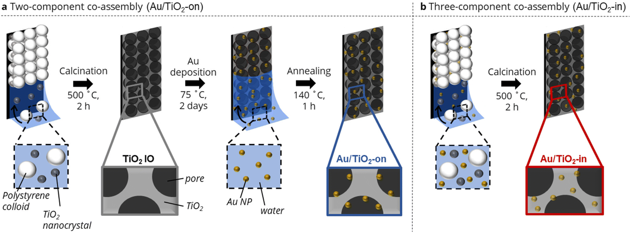 | ||
| Fig. 1 Schematic illustration of Au/TiO2 IO film synthesis in which Au NPs are placed either (a) on the TiO2 surface via a two-component co-assembly approach, or (b) in the TiO2 matrix via a three-component co-assembly approach. | ||
The Au/TiO2-in IO film was prepared through co-assembly of the same polystyrene (PS) templating colloids and TiO2 nanocrystals, but now in the presence of 5 nm citrate-capped Au NPs (Fig. 1b). The colloidal crystal film was similarly calcined to remove the templating colloids, with Au NPs now located in the TiO2 IO matrix. Note that PVP-capped Au NPs were not used in the preparation of Au/TiO2-in, as we have empirically found that the bulkier PVP ligands disrupted the macroscopic order of the IO films during co-assembly (Fig. S4b†). We emphasize the importance of using negatively charged citrate-capped Au NPs that electrostatically repel both the negatively charged PS colloids (−47 ± 0.4 mV) and the negatively charged TiO2 nanocrystals (−30.4 ± 1.2 mV), thereby providing sufficient colloidal stability for controlled self-assembly into an ordered IO film. We aimed to prepare Au/TiO2 IO films with 2 and 5 wt% Au. The actual Au loading in the Au/TiO2-in and -on films was determined by immersing each film separately in aqua regia for 48 h, followed by quantifying the amount of dissolved Au using inductively coupled plasma–mass spectrometry (ICP-MS). The ICP-MS results in Table 1 show close agreement between the expected and ICP-determined Au loading for the Au/TiO2-on sample. However, for the Au/TiO2-in sample, only about half of the Au loading that was used during the synthesis, was detected. Since the TiO2 remains porous after calcination at 500 °C, all Au NPs in the Au/TiO2 IO films are most likely chemically accessible for digestion by aqua regia, and should therefore be detected. The lower Au weight loading in the Au/TiO2-in films is therefore likely due to partial deposition of Au NPs on the walls of the glass vial used during the evaporation-induced three-component co-assembly, resulting in a lower Au content in the Au/TiO2-in film.
| Sample | Expected Au loading (wt%) | Measured Au loading (wt%) |
|---|---|---|
| Au/TiO2-on | 2.0 | 2.0 |
| 5.0 | 5.3 | |
| Au/TiO2-in | 2.0 | 0.8 |
| 5.0 | 3.2 |
Scanning electron microscopy (SEM) images of the 3 wt% Au/TiO2-in and 5 wt% Au/TiO2-on film confirm that the Au NP placement did not affect the overall macroscopic morphology of the TiO2 IO films (Fig. 2a and b). However, the Au NP size distribution was somewhat affected by the synthetic method (Fig. 2c). Whereas the NP size was largely preserved for Au/TiO2-on (4.9 ± 1.0 nm), some NP sintering was recorded for Au/TiO2-in (6.6 ± 1.7 nm). The broader NP size distribution of Au/TiO2-in was induced during the 500 °C calcination step, noting that for the Au/TiO2-on sample this step was performed before Au NP addition (Fig. 1). To check this, we performed the same calcination step on the as-prepared Au/TiO2-on film and indeed observed severe NP sintering with NPs exceeding 20 nm in diameter (Fig. S4c†), compared to a much smaller increase in size from 4.9 ± 1.0 nm to 6.6 ± 1.7 nm using the three-component assembly strategy (Fig. 2c). We thus conclude that the NPs on the TiO2 matrix in the Au/TiO2-on film were considerably less resistant to high temperature sintering than the NPs inside the TiO2 matrix in the Au/TiO2-in film.
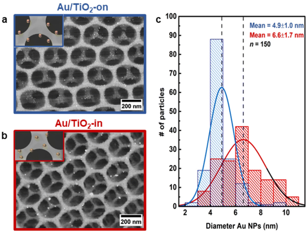 | ||
| Fig. 2 Structural characterization of Au/TiO2 IO films. SEM images of 5 wt% (a) Au/TiO2-on and 3 wt% (b) Au/TiO2-in. Au NPs are shown as bright white spots. Inset schematically depicts the expected Au NP placement in the TiO2 IO film. (c) Au NP size distribution in Au/TiO2 IO films, as determined from their SEM images (n = 150). Dashed lines indicate the mean NP size. Au/TiO2-in results are shown in red, Au/TiO2-on results are shown in blue. | ||
We employed electron tomography to visualize the placement of Au NP in the 3 wt% Au/TiO2-in and 5 wt% Au/TiO2-on sample. The tilt series and full 3D reconstruction for both samples can be viewed in Movies S1 and S2.† The snapshots of the tomographic reconstruction, as shown in Fig. 3 confirm that well-dispersed NPs are located in the macropores on top of the TiO2 surface for the Au/TiO2-on film (Fig. 3a). For the Au/TiO2-in film, the NPs are no longer exclusively located at the surface, but also within the TiO2 matrix, indicating NP embedding as expected (Fig. 3c). The embedding of NPs was also observed in the 1 wt% Au/TiO2-in film (Fig. S5†) and is likely independent of Au NP loading.
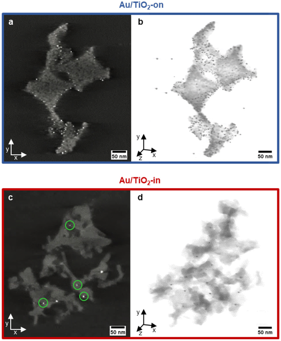 | ||
| Fig. 3 3D analysis of the NP placement using electron tomography. XY-slices taken from the 3D reconstruction showing the interior of the 5 wt% (a) Au/TiO2-on and 3 wt% (c) Au/TiO2-in IO films and the corresponding 3D XYZ views in (b and d). Au NPs are shown as bright white spots in (a and c) and dark spots in (b and d). The green circles in (c) indicate embedded Au NPs. | ||
Photocatalytic performance of the Au/TiO2 inverse opal films
The effect of NP placement in the Au/TiO2 IO films was evaluated using the photocatalytic degradation of methylene blue (MB) as a probe reaction. Upon light irradiation of TiO2 films, the photogenerated electron–hole pairs form reactive radical species, such as ˙OH and ˙O2−, that react with MB resulting in photodecomposition into colorless compounds.34,35 The reaction kinetics of MB degradation can therefore easily be tracked with UV-vis spectroscopy. To account for MB adsorption on the TiO2 IO surface, which decreases the MB concentration (by non-photocatalytic means),26 we quantified this adsorption effect by immersing the IO films individually in the MB solution in the absence of light until a stable absorption was achieved to indicate MB saturation (Fig. S6†). The adsorption effect was determined to be approximately 10% and 20% of the initial MB concentration for TiO2 and Au/TiO2 (-in and -on) IO films, respectively, in line with literature.36 All subsequent data shown have been corrected for this adsorption effect and thus, any decrease in MB concentration after correction can be directly attributed to photodegradation.We compared the MB photodegradation efficiency of Au/TiO2-in and Au-TiO2-on films. For completeness, we also tested a control TiO2 IO film without Au NPs, and a blank mixture containing only MB to account for any self-decomposition of MB.35 Fig. 4a indicates that the rate of MB photodegradation increased appreciably with the use of Au/TiO2 IO films, with the Au/TiO2-on films exhibiting the highest absolute photocatalytic activity. Interestingly, the photocatalytic activity did not scale linearly with metal loading (Fig. 4c). The Au/TiO2-in film exhibited a 1.2-fold increase in the first-order rate constant from 2.4 to 2.9 × 10⁻⁴ s−1 when increasing the weight loading from 1 to 3 wt%. Contrarily, the first-order rate constant decreased from 3.8 to 3.5 × 10⁻⁴ s−1 when increasing the weight loading from 2 to 5 wt% for the Au/TiO2-on film. ICP-MS analysis of the used Au/TiO2 IO films revealed that this is likely due to NP leaching (Table 2). For the Au/TiO2-on IO films, severe NP leaching occurred: 65 and 86% of the NPs leached from the 2 and 5 wt% Au/TiO2-on IO films, respectively. For the Au/TiO2-in samples, NP leaching was less pronounced: 25 and 44% NP leaching for the 1 and 3 wt% Au/TiO2-in films, respectively. The linear first-order kinetic plot of −ln(C/C0) over reaction time in Fig. 4b suggests that the majority of NP leaching occurred directly at the start of the photocatalytic test upon immersing the IO film into the MB solution. This implies that the 2 and 5 wt% Au/TiO2-on films contained a similar Au weight loading during the photocatalytic evaluation, which explains the lack of improvement in photoactivity with Au loading. Our results emphasize the importance of NP embedding within the TiO2 matrix to reduce NP leaching during liquid phase photocatalysis. The cycling stability tests in Fig. S8† further confirm that the Au/TiO2-in film exhibit a higher catalytic cycling stability as compared to the Au/TiO2-on film. ICP-MS analysis in Table S1† indicates that the lower cycling stability of Au/TiO2-on is correlated to increased Au NP leaching with repeated photocatalytic test cycles. We performed these photocatalytic cycling tests using Au/TiO2 films prepared at a reduced Au loading to verify that the Au/TiO2-on films are intrinsically more active, but less stable than the Au/TiO2-in films, and that these differences remain valid at different NP loadings. Our observations are consistent with our previous findings in related thermocatalytic gas- and liquid phase evaluation where NP embedding within the support matrix substantially increased the catalyst stability and consequently, the overall catalytic performance.37–42
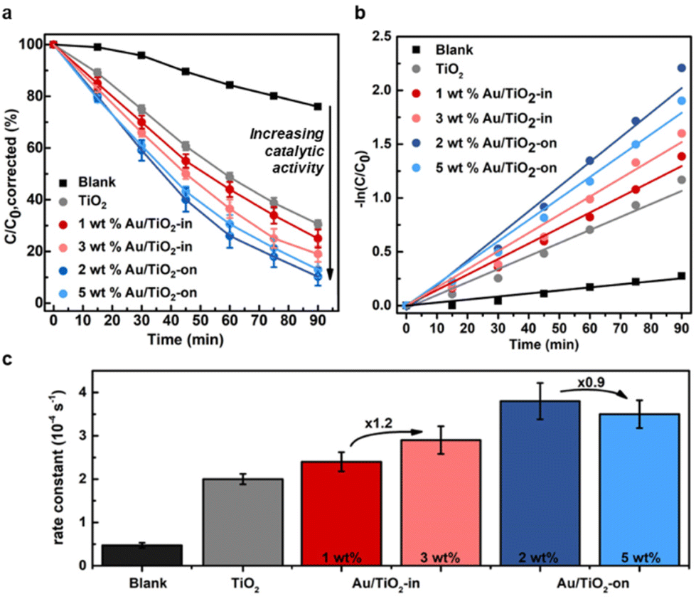 | ||
| Fig. 4 Photocatalytic degradation of 15 μM MB under light illumination (200–2500 nm). (a) Fraction of MB concentration remaining in the reaction solution (C/C0) as a function of time. (b) MB decomposition kinetics expressed as −ln(C/C0) over reaction time, and (c) the correspondingly derived first-order rate constants. | ||
| Sample | Experimentally measured Au loading after catalysis (wt%) | Leached Au NPs (%) |
|---|---|---|
| 2 wt% Au/TiO2-on | 0.7 | 65% |
| 5 wt% Au/TiO2-on | 0.7 | 86% |
| 1 wt% Au/TiO2-in | 0.6 | 25% |
| 3 wt% Au/TiO2-in | 1.8 | 44% |
Discussion
The Au/TiO2 IO films studied in this work exhibited enhanced photocatalytic activity in the photodegradation of MB with respect to TiO2 IO films, in line with literature.36,43–46 Interestingly, when comparing the rate constants of our 1 wt% Au/TiO2-in and 2 wt% Au/TiO2-on IO films (k = 2.4 and 3.8 × 10⁻⁴ s−1, respectively, Fig. 4c) to previously reported dye degradation studies using Au-loaded TiO2 with similar NP size, loading and light illumination conditions,36,43–45 we find that the IO films in this work were more active. Although direct comparisons between different photocatalytic studies are inherently complicated by differences in the photocatalytic conditions, the photocatalytic dye degradation rate constants from literature (k = 0.5 to 1.6 × 10⁻⁴ s−1) were substantially lower than those of all four Au/TiO2 IO films in this work (k = 2.4 to 3.8 × 10⁻⁴ s−1). The photocatalytic enhancement of the three-dimensional ordered IO structure (such as in this work), compared to the non-ordered TiO2 structures in literature,36,43–45 could be attributed to the distinctive photonic properties (e.g. slow light effect) and large surface area of the IOs.18–21 Chen et al. previously demonstrated that disordered TiO2 IO films still outperformed conventional, non-ordered TiO2 supported catalysts.47 Even when inducing significant disorder in the macropore structure by substituting 40% of the PS spheres with guest spheres that were 1.2 times larger, 50% of the photocatalytic enhancement in MB degradation was still retained. Their work indicates that the effect of partial disorder in the macroscopic structure of TiO2 IOs has relatively little impact on the photocatalytic activity.Our study demonstrates that the degree of NP leaching from the Au/TiO2 IO films depends on the NP placement. Even though the Au/TiO2-on films exhibited a higher absolute photocatalytic activity compared to the Au/TiO2-in films, further enhancement in activity was difficult to attain due to more severe NP leaching with increasing Au weight loading (Fig. 4, Table 2). Such leaching can, in part, be mitigated by partially embedding the NPs in the TiO2 matrix as we show for the Au/TiO2-in IO films. These results therefore demonstrate that the Au/TiO2 embedding is an important parameter in tuning the NP stability in Au/TiO2 systems, and that NP placement is an important parameter in controlling this. Additionally, our results show that the embedding also impacts the photocatalytic activity, as the activity of the Au/TiO2-in films is lower than the Au/TiO2-on films. This could be due to reduced light absorption by embedded Au NPs (Fig. S7†), more limited mass transport to- and from the Au NPs in the TiO2 matrix, and/or the larger average NP size in the Au/TiO2-in films (Fig. 2c).48 In particular, the transfer of photogenerated electrons from the NP to TiO2 upon plasmon-induced light absorption has been proposed to explain visible-light photoactivity of Au-decorated TiO2 photocatalysts.46,48 The co-assembly strategy can further be exploited to develop NP IO films with an optimized NP embedding to achieve a combination of high photocatalytic activity and high resistance against leaching.
In this proof of concept study, IO films were prepared on small Si wafer substrates. We remark that our co-assembly strategy allows flexibility both in the size and morphology of the substrates onto which the IO films are assembled, which enables easy scaling to assemble IO films on larger substrates. Additionally, we have previously demonstrated that the evaporation-induced co-assembly approach can be applied to producing 3D catalyst powders in bulk (≈1 g scale batches).37,49 When scaling up, adjustments to the solvent evaporation rate and concentration of the building blocks are typically necessary to maintain the high quality and crack-free IO structure.26
Future directions lie in the synthetic development of more complex multi-component IO systems, and in applying the IO films to a broader range of photocatalytic applications. For instance, the co-assembly approach can be applied to embed semiconductor quantum dots (e.g., CdS) in a variety of supports built from colloidal nanocrystals such as TiO2 in this work, but also indium-tin-oxide (ITO), CuO, perovskite, and other photoresponsive nanocrystals.50–52 The NP embedding is expected to alter the band structure at these semiconductor–semiconductor junctions and find applications in solid-state photovoltalics.50 Separately, we anticipate that our colloidal co-assembly strategy can easily incorporate nanocrystals of different shapes,53 facets54 and crystalline structure7 in its assembly to further augment photocatalytic performance. Additionally, the sizes of the PS templating colloids, TiO2 NCs and Au NPs can easily be tuned, as their syntheses are decoupled from the preparation of IO films. For instance, the size of the Au NPs can be tuned to optimize the size-dependent photocatalytic activity of Au NPs.31,48 However, we emphasize that the size of the TiO2 NCs and Au NPs should be substantially smaller than the size of the PS colloids to maintain a homogeneous dispersion throughout the evaporation-induced co-assembly and to avoid a disordered packing of the PS colloids.49 Finally, we expect that our multi-component co-assembly strategy can be applied in a wider range of photocatalytic applications, such as pollutant removal,55,56 H2 production,57,58 and CO2 reduction,57,59 but also in other related fields of optoelectronics,60,61 photovoltaics,62–64 and (bio)sensors.25,65
Conclusion
This work presents an evaporation-induced multi-component co-assembly strategy to tune the placement of Au NPs either on or in TiO2 inverse opal films, which was verified using electron tomography. The highly ordered and macroporous inverse opal structure was preserved when incorporating Au NPs in these Au/TiO2 inverse opal films. Photocatalytic evaluation using methylene blue degradation demonstrated that a higher absolute photocatalytic activity was obtained when Au NPs were deposited on the TiO2 matrix. However, such films were more prone to both NP sintering during high temperature treatments, and to NP leaching during photocatalysis. In contrast, films prepared with Au NPs embedded inside the TiO2 matrix exhibited improved thermal stability, and less metal leaching during liquid phase photocatalysis. Altogether, this study presents versatile co-assembly synthetic strategies to strategically control the placement of NPs in inverse opal structures for photochemical conversions.Author contributions
M. B.: Conceptualization, methodology, investigation, data analysis, visualization, original draft, review and editing. K. R. G. L.: Methodology, investigation, data analysis, visualization, supervision, review and editing. S. G.: Methodology. N. N.: Methodology. N. V.: Investigation. M. A.: Review and editing. J. E. S. v. d. H.: Supervision, resources, review and editing, project administration, funding acquisition. J. A.: Supervision, resources, review and editing, project administration, funding acquisition.Data availability
The data supporting this article have been included as part of the ESI.† Our raw data is now on Harvard dataverse (https://doi.org/10.7910/DVN/0KH3L9)Conflicts of interest
The authors declare no conflicts of interest.Acknowledgements
This work was supported by the U. S. Defense Threat Reduction Agency (DTRA) under Award #HDTR1211001612. Electron tomography work was supported by the Starting PI Fund of the Electron Microscopy Center at Utrecht University. Physical characterization was performed at the Center for Nanoscale Systems (CNS), a member of the National Nanotechnology Coordinated Infrastructure Network (NNCI), which is supported by the National Science Foundation under NSF ECCS award #1541959. M. B. acknowledges financial support from the Henrik Mullerfonds and Science for Sustainability community at Utrecht University. K. R. G. L. acknowledges financial support from the Agency for Science, Technology and Research (A*STAR) Singapore National Science Scholarship (PhD). J. E. S. v. d. H. acknowledges funding from the NWO Veni project with project number VI.Veni.212.046 which is financed by the Dutch Research Council (NWO).References
- I. Ahmad, Y. Zou, J. Yan, Y. Liu, S. Shukrullah, M. Y. Naz, H. Hussain, W. Q. Khan and N. R. Khalid, Adv. Colloid Interface Sci., 2023, 311, 102830 CrossRef CAS PubMed.
- M. R. Hoffmann, S. T. Martin, W. Choi and D. W. Bahnemann, Chem. Rev., 1995, 95, 69–96 CrossRef CAS.
- X. Chen and S. S. Mao, Chem. Rev., 2007, 107, 2891–2959 CrossRef CAS PubMed.
- J. Schneider, M. Matsuoka, M. Takeuchi, J. Zhang, Y. Horiuchi, M. Anpo and D. W. Bahnemann, Chem. Rev., 2014, 114, 9919–9986 CrossRef CAS PubMed.
- V. Seiß, S. Thiel and M. Eichelbaum, Inorganics, 2022, 10, 139 CrossRef.
- C. B. Anucha, I. Altin, E. Bacaksiz and V. N. Stathopoulos, Chem. Eng. J. Adv., 2022, 10, 100262 CrossRef CAS.
- Y. Yu, W. Wen, X.-Y. Qian, J.-B. Liu and J.-M. Wu, Sci. Rep., 2017, 7, 41253 CrossRef CAS PubMed.
- Y. Ma, X. Wang, Y. Jia, X. Chen, H. Han and C. Li, Chem. Rev., 2014, 114, 9987–10043 CrossRef CAS PubMed.
- S. Linic, P. Christopher and D. B. Ingram, Nat. Mater., 2011, 10, 911–921 CrossRef CAS PubMed.
- H. Cheng, K. Fuku, Y. Kuwahara, K. Mori and H. Yamashita, J. Mater. Chem. A, 2015, 3, 5244–5258 RSC.
- P. Wang, B. Huang, Y. Dai and M.-H. Whangbo, Phys. Chem. Chem. Phys., 2012, 14, 9813–9825 RSC.
- J. Piella, N. G. Bastús and V. Puntes, Chem. Mater., 2016, 28, 1066–1075 CrossRef CAS.
- S. Lv, Y. Du, F. Wu, Y. Cai and T. Zhou, Nanoscale Adv., 2022, 4, 2608–2631 RSC.
- A. Naldoni, M. D'Arienzo, M. Altomare, M. Marelli, R. Scotti, F. Morazzoni, E. Selli and V. Dal Santo, Appl. Catal., B, 2013, 130–131, 239–248 CrossRef CAS.
- J. I. L. Chen, E. Loso, N. Ebrahim and G. A. Ozin, J. Am. Chem. Soc., 2008, 130, 5420–5421 CrossRef CAS PubMed.
- J. E. S. van der Hoeven, A. V. Shneidman, N. J. Nicolas and J. Aizenberg, Acc. Chem. Res., 2022, 55, 1809–1820 CrossRef CAS PubMed.
- R. Guo, X. Hu, X. Chen, Z. Bi, J. Wang and W. Pan, Small, 2023, 19, 2207767 CrossRef CAS PubMed.
- J. I. L. Chen and G. A. Ozin, J. Mater. Chem., 2009, 19, 2675–2678 RSC.
- K. R. Phillips, G. T. England, S. Sunny, E. Shirman, T. Shirman, N. Vogel and J. Aizenberg, Chem. Soc. Rev., 2016, 45, 281–322 RSC.
- L. Wang, T. R. Mogan, K. Wang, M. Takashima, B. Ohtani and E. Kowalska, ChemEngineering, 2022, 6, 33 CrossRef CAS.
- J. I. L. Chen, G. von Freymann, S. Y. Choi, V. Kitaev and G. A. Ozin, Adv. Mater., 2006, 18, 1915–1919 CrossRef CAS.
- X.-C. Ma, Y. Dai, L. Yu and B.-B. Huang, Light: Sci. Appl., 2016, 5, e16017 CrossRef CAS PubMed.
- M. W. Knight, Y. Wang, A. S. Urban, A. Sobhani, B. Y. Zheng, P. Nordlander and N. J. Halas, Nano Lett., 2013, 13, 1687–1692 CrossRef CAS PubMed.
- G.-Y. Yao, Q.-L. Liu and Z.-Y. Zhao, Catalysts, 2018, 8, 236 CrossRef.
- M. S. Rodrigues, D. Costa, R. P. Domingues, M. Apreutesei, P. Pedrosa, N. Martin, V. M. Correlo, R. L. Reis, E. Alves, N. P. Barradas, P. Sampaio, J. Borges and F. Vaz, Appl. Surf. Sci., 2018, 438, 74–83 CrossRef CAS.
- J. H. Han, A. V. Shneidman, D. Y. Kim, N. J. Nicolas, J. E. S. van der Hoeven, M. Aizenberg and J. Aizenberg, Angew. Chem., Int. Ed., 2022, 61, e202111048 CrossRef CAS PubMed.
- Y. Vasquez, M. Kolle, L. Mishchenko, B. D. Hatton and J. Aizenberg, ACS Photonics, 2014, 1, 53–60 CrossRef CAS.
- B. Hatton, L. Mishchenko, S. Davis, K. H. Sandhage and J. Aizenberg, Proc. Natl. Acad. Sci. U. S. A., 2010, 107, 10354–10359 CrossRef CAS PubMed.
- A. Zulfiqar, F. Temerov and J. J. Saarinen, ACS Omega, 2020, 5, 11595–11604 CrossRef CAS PubMed.
- A. Rostek, D. Mahl and M. Epple, J. Nanopart. Res., 2011, 13, 4809–4814 CrossRef CAS.
- C. Liang, J. Y. Cheong, G. Sitaru, S. Rosenfeldt, A. S. Schenk, S. Gekle, I.-D. Kim and A. Greiner, Adv. Mater. Interfaces, 2022, 9, 2100867 CrossRef CAS.
- F. Chen, X. Li, J. Hihath, Z. Huang and N. Tao, J. Am. Chem. Soc., 2006, 128, 15874–15881 CrossRef CAS PubMed.
- H. Al-Johani, E. Abou-Hamad, A. Jedidi, C. M. Widdifield, J. Viger-Gravel, S. S. Sangaru, D. Gajan, D. H. Anjum, S. Ould-Chikh, M. N. Hedhili, A. Gurinov, M. J. Kelly, M. El Eter, L. Cavallo, L. Emsley and J.-M. Basset, Nat. Chem., 2017, 9, 890–895 CrossRef CAS PubMed.
- M. G. Kim, J. E. Lee, K. S. Kim, J. M. Kang, J. H. Lee, K. H. Kim, M. Cho and S. G. Lee, New J. Chem., 2021, 45, 3485–3497 RSC.
- I. Khan, K. Saeed, I. Zekker, B. Zhang, A. H. Hendi, A. Ahmad, S. Ahmad, N. Zada, H. Ahmad, L. A. Shah, T. Shah and I. Khan, Water, 2022, 14, 242 CrossRef CAS.
- N. Sahu and K. M. Parida, Kinet. Catal., 2012, 53, 197–205 CrossRef CAS.
- T. Shirman, T. J. Toops, E. Shirman, A. V. Shneidman, S. Liu, K. Gurkin, J. Alvarenga, M. P. Lewandowski, M. Aizenberg and J. Aizenberg, Catal. Today, 2021, 360, 241–251 CrossRef CAS.
- J. E. S. van der Hoeven, S. Krämer, S. Dussi, T. Shirman, K.-C. K. Park, C. H. Rycroft, D. C. Bell, C. M. Friend and J. Aizenberg, Adv. Funct. Mater., 2021, 31, 2106876 CrossRef CAS.
- A. Filie, T. Shirman, A. C. Foucher, E. A. Stach, M. Aizenberg, J. Aizenberg, C. M. Friend and R. J. Madix, J. Catal., 2021, 404, 943–953 CrossRef CAS.
- S. K. Kaiser, J. E. S. van der Hoeven, G. Yan, K. R. G. Lim, H. T. Ngan, S. Garg, M. Karatok, M. Aizenberg, J. Aizenberg, P. Sautet, C. M. Friend and R. J. Madix, ACS Catal., 2023, 13, 12092–12103 CrossRef CAS.
- K. R. G. Lim, S. K. Kaiser, H. Wu, S. Garg, M. Perxés Perich, J. E. S. van der Hoeven, M. Aizenberg and J. Aizenberg, Nat. Catal., 2024, 7, 172–184 CrossRef CAS.
- K. R. G. Lim, S. K. Kaiser, H. Wu, S. Garg, C. R. O’Connor, C. Reece, M. Aizenberg and J. Aizenberg, ACS Nano, 2024, 18(24), 15958–15969 CrossRef CAS PubMed.
- A. Waheed, Q. Shi, N. Maeda, D. M. Meier, Z. Qin, G. Li and A. Baiker, Catalysts, 2020, 10, 933 CrossRef CAS.
- L. I. Jinga, G. Popescu-Pelin, G. Socol, S. Mocanu, M. Tudose, D. C. Culita, A. Kuncser and P. Ionita, Nanomaterials, 2021, 11, 1605 CrossRef CAS PubMed.
- G. K. Naik, P. M. Mishra and K. Parida, Chem. Eng. J., 2013, 229, 492–497 CrossRef CAS.
- P. Birnal, M. C. Marco de Lucas, I. Pochard, F. Herbst, O. Heintz, L. Saviot, B. Domenichini and L. Imhoff, Appl. Surf. Sci., 2023, 609, 155213 CrossRef CAS.
- J. I. L. Chen, G. von Freymann, V. Kitaev and G. A. Ozin, J. Am. Chem. Soc., 2007, 129, 1196–1202 CrossRef CAS PubMed.
- L. Lin, Q. Zhong, Y. Zheng, Y. Cheng, R. Qi and R. Huang, Chem. Phys. Lett., 2021, 770, 138457 CrossRef CAS.
- E. Shirman, T. Shirman, A. V. Shneidman, A. Grinthal, K. R. Phillips, H. Whelan, E. Bulger, M. Abramovitch, J. Patil, R. Nevarez and J. Aizenberg, Adv. Funct. Mater., 2018, 28, 1704559 CrossRef.
- T. Ling, S. A. Kulinich, Z.-L. Zhu, S.-Z. Qiao and X.-W. Du, Adv. Funct. Mater., 2014, 24, 707–715 CrossRef CAS.
- L. Xia, L. Xu, J. Song, R. Xu, D. Liu, B. Dong and H. Song, Sci. Rep., 2015, 5, 10838 CrossRef CAS PubMed.
- Y. Wu, B. Huang, Z. Meng, S. Zhang and S. Wu, Chem. Eng. J., 2022, 432, 134409 CrossRef CAS.
- J. H. Han, A. V. Shneidman, D. Y. Kim, N. J. Nicolas, J. E. S. van der Hoeven, M. Aizenberg and J. Aizenberg, Angew. Chem., Int. Ed., 2022, 61, e202111048 CrossRef CAS PubMed.
- G. Son, Y. Li, A. V. Shneidman, J. H. Han, M. Aizenberg, P. Sautet and J. Aizenberg, Chem. Mater., 2023, 35, 9505–9516 CrossRef CAS.
- A. Ayati, A. Ahmadpour, F. F. Bamoharram, B. Tanhaei, M. Mänttäri and M. Sillanpää, Chemosphere, 2014, 107, 163–174 CrossRef CAS PubMed.
- H. Peeters, M. Keulemans, G. Nuyts, F. Vanmeert, C. Li, M. Minjauw, C. Detavernier, S. Bals, S. Lenaerts and S. W. Verbruggen, Appl. Catal., B, 2020, 267, 118654 CrossRef CAS.
- M. Bowker, L. Millard, J. Greaves, D. James and J. Soares, Gold Bull., 2004, 37, 170–173 CrossRef CAS.
- G. Wu, T. Chen, W. Su, G. Zhou, X. Zong, Z. Lei and C. Li, Int. J. Hydrogen Energy, 2008, 33, 1243–1251 CrossRef CAS.
- Z. Fu, Q. Yang, Z. Liu, F. Chen, F. Yao, T. Xie, Y. Zhong, D. Wang, J. Li, X. Li and G. Zeng, J. CO2 Util., 2019, 34, 63–73 CrossRef CAS.
- H. Chen, G. Liu and L. Wang, Sci. Rep., 2015, 5, 10852 CrossRef CAS PubMed.
- L.-P. Wu, W.-G. Wang, D. Mo, J.-L. Duan and X.-J. Li, Inorg. Nano-Met. Chem., 2023, 1–9 Search PubMed.
- I. Vangelidis, A. Theodosi, M. J. Beliatis, K. K. Gandhi, A. Laskarakis, P. Patsalas, S. Logothetidis, S. R. P. Silva and E. Lidorikis, ACS Photonics, 2018, 5, 1440–1452 CrossRef CAS.
- M. Notarianni, K. Vernon, A. Chou, M. Aljada, J. Liu and N. Motta, Sol. Energy, 2014, 106, 23–37 CrossRef CAS.
- X. Cui, Y. Chen, M. Zhang, Y. Wei Harn, J. Qi, L. Gao, Z. Lin Wang, J. Huang, Y. Yang and Z. Lin, Energy Environ. Sci., 2020, 13, 1743–1752 RSC.
- L. Guo, Z. Li, K. Marcus, S. Navarro, K. Liang, L. Zhou, P. D. Mani, S. J. Florczyk, K. R. Coffey, N. Orlovskaya, Y.-H. Sohn and Y. Yang, ACS Sens., 2017, 2, 621–625 CrossRef CAS PubMed.
Footnotes |
| † Electronic supplementary information (ESI) available. See DOI: https://doi.org/10.1039/d4nr01200c |
| ‡ These authors contributed equally. |
| This journal is © The Royal Society of Chemistry 2024 |