
 Open Access Article
 This Open Access Article is licensed under a Creative Commons Attribution-Non Commercial 3.0 Unported Licence
Controlled synthesis, properties, and applications of ultralong carbon nanotubes
Kangkang
Wang
 ,
Fei
Wang
,
Qinyuan
Jiang
,
Ping
Zhu
,
Khaixien
Leu
and
Rufan
Zhang
*
,
Fei
Wang
,
Qinyuan
Jiang
,
Ping
Zhu
,
Khaixien
Leu
and
Rufan
Zhang
*
Department of Chemical Engineering, Tsinghua University, Beijing 100084, China. E-mail: zhangrufan@tsinghua.edu.cn
First published on 5th July 2024
Abstract
Carbon nanotubes (CNTs) are typical one-dimensional nanomaterials which have been widely studied for more than three decades since 1991 because of their excellent mechanical, electrical, thermal, and optical properties. Among various types of CNTs, the ultralong CNTs which have lengths over centimeters and defect-free structures exhibit superior advantages for fabricating superstrong CNT fibers, CNT-based chips, transparent conductive films, and high-performance cables. The length, orientation, alignment, defects, cleanliness, and other microscopic characteristics of CNTs have significant impacts on their fundamental physical properties. Therefore, the controlled synthesis and mass production of high-quality ultralong CNTs is the key to fully exploiting their extraordinary properties. Despite significant progress made in the study of ultralong CNTs during the past three decades, the precise structural control and mass production of ultralong CNTs remain a great challenge. In this review, we systematically summarize the growth mechanism and controlled synthesis strategies of ultralong CNTs. We also introduce the progress in the applications of ultralong CNTs. Additionally, we summarize the scientific and technological challenges facing the mass production of ultralong CNTs and provide an outlook and in-depth discussion on the future development direction.
1. Introduction
Carbon nanotubes (CNTs) are one-dimensional Dirac materials that have exceptional electrical, mechanical, optical, and thermal properties.1–3 CNTs have wide applications in many cutting-edge fields such as carbon-based integrated circuits, super-strong fibers, sensing, mechanical energy storage, and flexible wearable devices, etc.4–8 For instance, CNTs have a very high Young's modulus of up to 1 TPa and a high tensile strength of up to 100 GPa, which far exceeds that of steel.9 Furthermore, CNTs have excellent electrical conductivity which can withstand a current density of up to 109 A cm−2, much higher than that of copper wires.5,10 Additionally, CNTs have unique electromagnetic properties and can be used to make high-frequency electronic devices and electromagnetic shielding materials.11,12 CNTs have shown promising application prospects in fields such as aerospace, information technology, energy storage, environment protection, military, and biomedicine.13–16 Among the various factors affecting the properties and performance of CNTs, the length, defect concentration, crystallinity, chirality, and alignment of CNTs are the most significant ones.5–7 Especially, the length of individual CNTs is a critical factor which determines the properties of macroscopic CNT fibers and films, e.g., their electrical conductivity, thermal conductivity, tensile strength, and tensile strain, etc.8 Therefore, it is highly significant to make individual CNTs as long as possible. According to the differences in the alignments, lengths, and morphologies of CNTs, they can be divided into three different categories, which are agglomerated CNTs, vertically aligned CNT arrays (VACNTs), and horizontally aligned CNT arrays (HACNTs).9 Generally, the agglomerated CNTs and VACNTs have short lengths shorter than a millimeter and many structural defects.10–17 In comparison, the HACNTs usually grow on flat substrates and have very few structural defects, which render them with excellent electrical, mechanical, and thermal properties.9 Moreover, the HACNTs can also be further categorized into two sub-types based on their different growth mechanisms. The first kind of HACNTs is usually grown on substrates such as quartz18,19 and single crystal MgO20 with a base-growth mechanism. The base-growth HACNTs are also typically less than one millimeter in length and grow slowly.21,22 In contrast, the second kind of HACNTs are grown on silicon substrates with a flying kite-like tip-growth mechanism.23–29 The tip-growth HACNTs have very fast growth rates and their lengths can be as long as several centimeters or even several decimeters,9,30 which are much longer than other types of CNTs. Therefore, the tip-growth HACNTs are usually called “ultralong CNTs”.8,30,31 Because of the macroscale lengths, good alignment, perfect structures, and excellent properties, ultralong CNTs are ideal candidates for fabricating CNT fibers, transparent conductive films, conductive wires, and carbon-based integrated circuits.8However, the biggest challenge facing ultralong CNTs is how to realize their mass production. The yields of ultralong CNTs are usually much lower than that of other types of CNTs, which severely hinders their application in various fields. Besides, it is also essential to overcome the challenges like precise structural and morphological control the high cost, and the functionalization of CNT fibers.17–20,32 It is worth noting that many cutting-edge fields propose very stringent requirements on the structure of CNTs.21 For example, transparent conductive films, electrothermal films, and CNT fibers usually require CNTs with longer monomer lengths to reduce contact thermal and electrical resistance, and enhance stress transfer between tubes.22–24 In carbon-based integrated circuit applications, CNTs with good orientation are necessary to construct tunneling transistor structures.25,26 Therefore, achieving controlled synthesis of CNTs with macroscopic size, high crystallinity, and low defect density is crucial for their wide applications.27–29
In the past two decades, people have successfully prepared ultralong CNTs with macroscopic lengths, perfect structures, controlled morphologies, and excellent properties. Many efforts have been made in the study of the growth mechanism, synthesis methods, property study, and application exploitation of ultralong CNTs (Fig. 1).30,31,33 In this paper, we review recent research progress on the controlled preparation of ultralong CNTs and their properties. We also analyze the challenges and future development directions. This review is expected to provide more inspiration and reference for the mass production and future development of ultralong CNTs.
 | ||
| Fig. 1 Growth mechanism, controlled synthesis, and excellent properties of ultralong CNTs.30,31,33 Reproduced from ref. 30 with permission from Wiley-VCH, copyright 2023. Reproduced from ref. 31 with permission from American Chemical Society, copyright 2023. Reproduced from ref. 33 with permission from American Chemical Society, copyright 2024. | ||
2. Growth mechanism of ultralong CNTs
There are three main methods for synthesizing CNTs: arc discharge, laser ablation, and chemical vapor deposition (CVD).34–37 Among them, the CVD methods have shown many advantages in controlling the structure and morphology, specific orientation growth, and mass production of CNTs.38 After decades of development, CVD has become a mature technology for the preparation of various thin films and nanomaterials.39,40 This section mainly discusses the CVD growth mechanism of ultralong CNTs.2.1. Mechanism for nucleation and growth of general CNTs
The mechanism of nucleation and growth of CNTs is a complex physicochemical process involving the arrangement and assembly of carbon atoms on the nanoscale.41–43 Nucleation is the first stage of CNT growth, where carbon atoms form the initial tubular structure on the substrate surface.44 In this process, carbon atoms must first be adsorbed on the substrate surface and then aggregated into a nucleation under suitable conditions through surface diffusion.45 This nucleus is typically a ring structure that consists of a few carbon atoms that are hybridized by sp2 to form a six-membered ring, which is connected by σ-bonds.46 As the nucleus grows, carbon atoms continue to adsorb and join the ring structure, turning it into a tube. After nucleation, CNTs enter the growth phase, where the key is how the carbon atoms are deposited along the tube wall in a specific orientation.47,48After adsorption on the surface, carbon atoms can be added to the growing CNTs in three different ways. (1) Additive method: hydrocarbons like methane or hydrogen are usually used as carbon sources in the CVD process. Carbon atoms first react with hydrogen atoms to form small molecules such as methane, which then decompose at high temperatures. This releases carbon atoms that stick to the surface of the nanotubes and grow along the tube walls. (2) Catalytic growth: catalysts like iron, nickel, or cobalt are pre-coated on the substrates. Carbon atoms react with these catalyst particles at high temperatures to produce CNTs. The catalyst plays an important role by providing a suitable surface and active sites for carbon atoms to nucleate and grow. (3) Free radical growth: this method involves the decomposition of hydrocarbon molecules to produce free radicals under plasma or laser irradiation. These free radicals then migrate and deposit carbon atoms on the surface, promoting the growth of CNTs.49–52 It is important to note that temperature, pressure, gas flow, catalyst selection, and other factors can significantly impact the growth of CNTs.53 By controlling these conditions, it is possible to modulate the structure (e.g., wall number, diameter, length) and properties (e.g., mechanical, electrical, and chemical) of CNTs to a certain extent.54
2.2. Mechanism for base-growth and tip-growth mode of CNTs
Understanding the growth mechanisms and modes of CNTs is essential to control their structures.55 As shown in Fig. 2a, the CVD process can be divided into two mechanisms based on the phase states of the catalysts: vapor–liquid–solid (VLS) and vapor–solid–solid (VSS).56 Researchers proposed two main growth modes to understand the growth behaviors of CNTs: tip-growth and base-growth modes (Fig. 2b).56,57 These growth modes are proposed to describe the motion behavior of the catalysts and the forces between the catalysts and substrates during the growth of CNTs. | ||
| Fig. 2 (a) Schematic diagram of the VLS and VSS growth mechanisms of CNTs. (b) Diagram of base-growth and tip-growth modes of CNTs.56 Reproduced from ref. 56 with permission from Wiley-VCH, copyright 2019. | ||
The base-growth mode of CNTs is mainly influenced by low temperatures.64 There are two reasons for this phenomenon. Firstly, the lower temperature makes the catalyst particles have larger sizes which is better for them to infiltrate the substrate surface, creating a stronger force. This makes it difficult for the catalysts to leave the substrate when CNTs are grown, which ultimately leads to the emergence of the base-growth mode.65 Secondly, the temperature difference between the substrate and the gas flow caused by the low temperature is smaller, which weakens the effect of thermal buoyancy and thus makes it difficult for the catalyst to be lifted and enter the laminar zone of the gas flow.66 In addition to the temperature, the types of catalysts and their melting points also affect the growth modes of CNTs.67 Concretely, catalysts with low melting points are more likely to present a liquid state and show poorer wettability on the substrates, leading to a tip-growth mode of CNTs. However, catalysts with high melting points always maintain a near-solid state, have poorer mobility, a stronger force with the substrates, and show better wettability on the substrate surface, resulting in a base-growth mode.
Tip-growth mode is a better way to generate horizontal arrays of CNTs that have a perfect structure and macroscopic length.70 These arrays can be utilized to create super-strong macroscopic materials. In this mode, the CNTs float in a reactive gas flow that is laminar, making it easier for them to contact and react with carbon source molecules. This results in CNTs with a high growth rate.71 Furthermore, the growth of CNTs in the airflow is not easily interfered with or controlled by the substrate, which avoids excessive defects, thus obtaining CNTs with a more perfect structure. In contrast, CNTs are more prone to create defects and be shorter in length via base-growth mode due to the limitations of the substrate and the mass transfer resistance during the growth process.
In summary, there are two main growth modes for CNTs, which are base-growth mode and tip-growth mode. In the actual growth process, the two growth modes usually coexist, especially in the horizontal array growth of CNTs. Because it is challenging to maintain the catalyst's morphology and the microenvironment consistent. Tip-growth mode is more suitable for producing ultralong CNTs with faster growth rates and macroscale lengths.17 This is because high growth rates require a substantial amount of carbon source molecules in the gas phase to decompose on the surface of the catalyst particles. Catalyst particles that float in the gas stream are more likely to satisfy this condition than immobile particles on the substrate. The immobile catalyst particles' catalytic activity is more likely to be disrupted by the substrate, and the mass transfer resistance on the surface is also more significant than that of catalyst particles floating in the gas stream.
2.3. Growth mechanism of ultralong CNTs
Horizontal arrays of CNTs can be prepared through either base-growth mode or tip-growth mode. In the base-growth mode, the CNTs grow on single-crystal quartz or sapphire substrates and follow a crawling growth pattern.72,73 While this method can produce arrays with high areal density and high orientation, the growth process is hindered by van der Waals forces on the substrate.74 Consequently, the CNTs have slow growth rates and have a limited length shorter than 0.1 mm.75 This is insufficient for many applications that require CNTs with macroscale lengths. In contrast, the tip-growth mode uses a unique “kite-like growth” mechanism.57 Specifically, the CNTs are subjected to the synergistic effects of drag force, thermal buoyancy, and van der Waals force. One end of a CNT is fixed to the substrate while the other end with a catalyst particle floats in the gas phase. This method can produce horizontal arrays of ultralong CNTs with lengths of up to centimeters or even decimeters. Significant progress has been made in the synthesis of ultralong CNTs over the past two decades (Fig. 3).7,30,31,76–81 These ultralong CNTs are better suited for many applications due to their superior performance. | ||
| Fig. 3 Timeline of major milestones in the controlled synthesis of ultralong CNTs.7,30,31,76–81 Reproduced from ref. 7 with permission from Royal Society of Chemistry, copyright 2017. Reproduced from ref. 30 with permission from Wiley-VCH, copyright 2022. Reproduced from ref. 31 with permission from American Chemical Society, copyright 2023. Reproduced from ref. 76 with permission from Springer Nature, copyright 2004. Reproduced from ref. 77 with permission from Springer Nature, copyright 2017. Reproduced from ref. 78 with permission from Springer Nature, copyright 2018. Reproduced from ref. 79 with permission from Springer Nature, copyright 2019. Reproduced from ref. 80 with permission from American Association for the Advancement of Science, copyright 2020. Reproduced from ref. 81 with permission from American Chemical Society, copyright 2021. | ||
In the tip-growth process of ultralong CNTs, the catalysts collide with gas molecules in the gas phase. This collision enhances the reaction and mass transfer process, leading to a growth rate of up to 80–90 μm s−1.82 The growth process is almost unaffected by the substrate, which enables carbon atoms to be assembled rapidly and precisely at the interface between the catalysts and the CNTs. This results in a defect-free structure with a length of up to 65 cm.79 Moreover, the airflow traction can provide good orientation for the ultralong CNTs, allowing them to form a well-oriented array along the flow line.
During the tip-growth mode of ultralong CNTs, thermal buoyancy force plays an essential role in making the CNTs be lifted off from the substrate surface. This force is generated by the temperature difference between the substrate and the surrounding airflow.30 The catalyst particles located at the tip of the CNTs remain unaffected by the substrate wall effect and can directly contact the carbon source in the gas. This allows for the high-speed growth of defect-free CNTs. However, there are two unsolved issues in the growth system of ultralong CNTs, which are (1) the reason for the temperature difference between the substrate and the gas stream, and (2) the nature of thermal buoyancy.
Researchers have proposed several explanations for the temperature difference observed between the substrate and the airflow during the preparation of ultralong CNTs. Liu et al. believed that the temperature difference was caused by the difference in heating rates between the substrate and the airflow.64 Zhang et al. further extended this theory to other synthesis methods.83 Li et al. pointed out that the substrate was significantly heated by the heat conduction and the radiation from the reactor wall, resulting in a substantial temperature difference with the cold air flow from upstream (Fig. 4a and b).57 Although these theories explained some experimental phenomena and provided guidance for experimental design, they did not offer a quantitative relationship between the temperature difference and the growth conditions (such as growth temperature, gas flow rate, and substrate material). The spiral growth theory of CNTs suggests that ultralong CNTs can be considered as a linear carbon polymer. Zhang et al. found that their growth follows the Schulz–Flory (SF) distribution.84,85 The probability of the catalyst particles remaining active enough to support the growth of CNTs when the unit length was increased was defined as α (Fig. 4c). Both theoretical calculations and experimental results demonstrated that, regardless of α, the number density of CNTs decreases irreversibly as their length increases, which is an irreversible trend (Fig. 4d–f). To increase the number density and length of ultralong CNTs, the value of α should be increased as much as possible. This theory successfully explains the growth mechanism of ultralong CNT arrays.
 | ||
| Fig. 4 (a) Schematic illustration of the tip-growth mechanism of ultralong CNTs. (b) SEM image of SWCNT arrays grown across microtrenches.57 Reproduced from ref. 57 with permission from American Chemical Society, copyright 2007. (c) Illustration of tip-growth of ultralong CNTs based on Schulz–Flory distribution. (d) Atomic force microscopy image of a CNT with a catalyst nanoparticle on its tip. (e) Theoretical percentage and (f) theoretical number density of ultralong CNTs.84 Reproduced from ref. 84 with permission from American Chemical Society, copyright 2013. | ||
Previous studies have assumed that thermal buoyancy is due to natural convection (Fig. 5a and b).83,86 When there is a temperature difference between the substrate and the airflow, the air close to the substrate gets heated, creating a density gradient that drives natural convection. This causes the warmer gas to move upwards, lifting the CNTs and causing them to float above the substrate. However, this theory can only explain the growth of ultralong CNTs on horizontally placed substrates as the traction force due to natural convection is directly related to the direction of the density gradient. However, experimental studies have shown that ultralong CNTs can also be grown on vertical substrates.86 The direction of the thermal buoyancy force in this case does not coincide with the direction of the trailing force due to natural convection. This indicates that the theory is still incomplete and cannot fully explain the existing experimental phenomena.
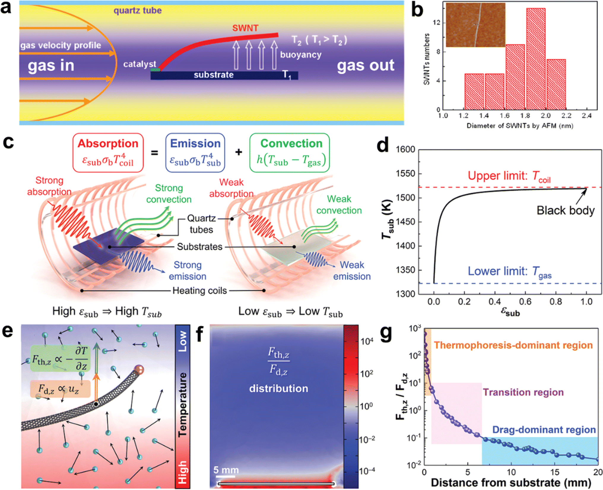 | ||
| Fig. 5 (a) Schematic diagram of the formation mechanism of thermal buoyancy. (b) Diameter distribution of SWCNTs by AFM. The inset is a typical AFM image of an individual SWCNT.83 Reproduced from ref. 83 with permission from American Chemical Society, copyright 2010. (c) Schematic illustration of the heat balance of the substrates with different emissivity. (d) Relationship between substrate temperature and substrate emissivity. (e) Thermophoretic force and drag force applied on a CNT in a non-uniform temperature field. (f) Distribution of the ratio of thermophoretic force to drag force in the vertical direction. (g) Distribution of the dominant regions of thermophoresis and drag.30 Reproduced from ref. 30 with permission from Wiley-VCH, copyright 2023. | ||
Zhang et al. first proposed a solution to two problems related to the growth of ultralong CNTs on flat substrates. They introduced the concept of the inherent thermal effect of the substrates and developed a heat balance model that describes the heat transfer behavior between the substrate and the surrounding environment (Fig. 5c and d).30 The model consists of absorption, emission, and convection. Based on this model, they found that the substrate temperature is higher than the airflow, and the substrate temperature is positively correlated with its emissivity. This explains the difference in the growth pattern of CNTs on single-crystal silicon and quartz substrates. Silicon has a high emissivity, which produces a strong intrinsic thermal effect of the substrate and thus a strong thermal buoyancy effect in its vertical direction, which is beneficial for the floating growth of CNTs.84 In contrast, quartz has a very low emissivity and a weak thermal buoyancy effect in its vertical direction, which is unfavorable for the floating growth of CNTs.87 In addition, the researchers analyzed the natural convection and thermophoresis phenomena induced by temperature gradients using computational fluid dynamics simulations (Fig. 5e–g). They quantified the relative magnitudes of the trailing and thermophoretic forces due to natural convection. By combining theoretical calculations with experiments, they proved that the thermophoretic force is the main driving force to make the CNTs float from the substrate. The direction of the thermophilic force is opposite to that of the temperature gradient and independent of the direction of the velocity of the airflow. It provides a lifting force perpendicular to the surface of the substrate for a long period for the ultralong CNTs, which can explain their growth behavior on the vertical substrate. Finally, they applied the theory of the intrinsic thermal effect of the substrate to the reactor design and artificially set the temperature gradient in the vertical or horizontal direction. This allowed them to realize the precise regulation of the density and orientation of ultralong CNT arrays.
3. Structural control of ultralong CNTs
Controlling the synthesis of ultralong CNTs is a difficult task due to its harsh growth conditions. The structural control of CNTs involves regulating their tube diameter, wall number, defect density, length, orientation, and array density.88 The initial step in preparing high-quality CNTs is to control the structural defects caused during growth. These defects, such as vacancies and doping, can significantly impact the properties of CNTs. It has been established through theoretical studies and experimental results that the presence of topological defects in CNTs can lead to a major reduction in their tensile strength by up to 50%.89 Moreover, the array density of CNTs has high demands for practical applications. For example, the International Business Machines Corporation (IBM) has proposed that the array density of CNTs utilized in integrated circuits should be 125 μm−1 (125![[thin space (1/6-em)]](https://www.rsc.org/images/entities/char_2009.gif) 000 mm−1).90 However, traditional methods of preparing ultralong CNTs usually result in an array density of no more than 50 mm−1, making practical application impossible.7 Hence, it is crucial to develop an effective and feasible method to prepare ultralong CNTs while controlling their structure.
000 mm−1).90 However, traditional methods of preparing ultralong CNTs usually result in an array density of no more than 50 mm−1, making practical application impossible.7 Hence, it is crucial to develop an effective and feasible method to prepare ultralong CNTs while controlling their structure.
3.1. Control of the length of ultralong CNTs
CNTs can be regarded as one-dimensional linear polymers composed of carbon atoms.91 The growth process of CNTs is similar to the formation of carbon atom chains. Catalyst particles adsorb and dissolve carbon atoms to create the active center, which initiates the increase of carbon atom chains. The reaction probability of carbon atoms in a discrete state is assumed to be the same for the entire reaction system.84 This assumption is consistent with the tip-growth mode of CNTs. Therefore, the growth process of CNTs can be seen as a process of carbon atom chain growth with equal probability, which is a kinetically controlled process.To increase the length of CNTs, a feasible method is to increase the catalytic activity of the catalyst as much as possible while ensuring a sufficient carbon source. Li et al. used iron and molybdenum as catalysts to prevent the polymerization of the catalysts with the CNT films extracted from spinnable arrays (Fig. 6a–c).86 They successfully prepared single-walled CNTs with a length of 18.5 cm. However, if the temperature exceeds the suitable growth temperature range of CNTs, the catalytic activity of the catalyst will increase, which in turn accelerates the cracking of the carbon source. Too much decomposed carbon source will generate amorphous carbon on the surface of the catalyst, which will reduce the activity of the catalyst. Therefore, it is crucial to maintain a constant temperature environment to ensure the activity of the catalyst. However, the tube furnace used for growing CNTs has only a limited constant temperature region, which is not favorable for the synthesis of ultralong CNTs. Wei et al. designed a “furnace-moving” method to prepare ultralong CNTs. They successfully obtained ultralong CNTs with lengths of 20 cm and 55 cm by adjusting the growth temperature, water vapor amount, gas velocity, and other parameters (Fig. 6d–j).82,84 Moreover, the ultralong CNTs have a perfect structure and excellent mechanical properties (Fig. 6k and l).
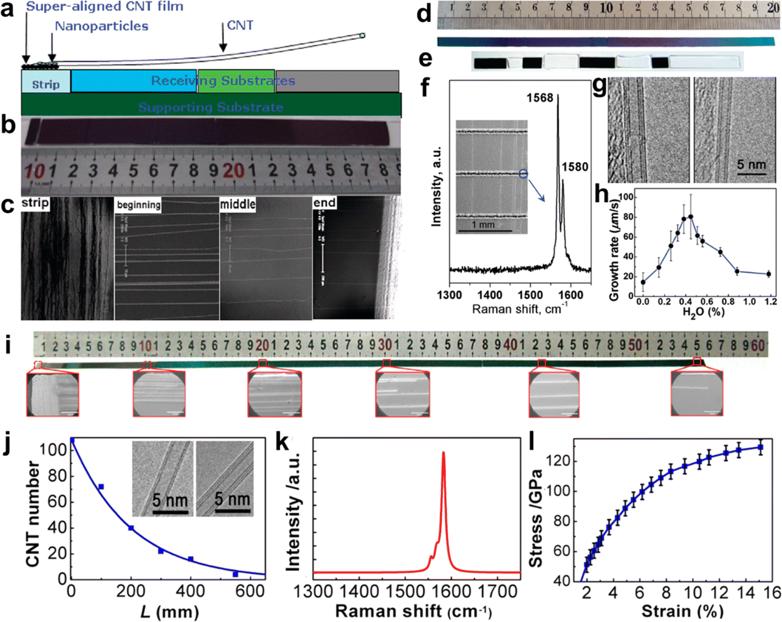 | ||
| Fig. 6 (a) Schematic of the growth method of the 18.5 cm long CNTs. (b) The optical images of an ultralong CNT array. (c) The SEM images of the strip and the beginning, middle, and end of the ultralong CNT array from left to right.86 Reproduced from ref. 86 with permission from American Chemical Society, copyright 2009. (d) Optical picture of the 20 cm long Si substrate. (e) Optical picture of the substrate connected by Si (dark substrates) and SiO2 (white substrates) substrates. (f) Raman spectra and (g) TEM pictures of CNTs. (h) Effect of water concentration on the growth rate of CNTs.82 Reproduced from ref. 82 with permission from American Chemical Society, copyright 2010. (i) SEM image of the 550 mm long CNTs. (j) Number of CNTs at different lengths on the substrate. Inset: TEM images of as-grown CNTs. (k) Raman spectrum of as-grown CNTs. (l) Mechanical properties of as-grown CNTs.84 Reproduced from ref. 84 with permission from American Chemical Society, copyright 2013. | ||
3.2. Control of the areal density of ultralong CNTs
The high-yield synthesis of ultralong CNTs is a prerequisite for their wide application.92 However, the low catalyst utilization and aggregation of catalyst particles during the growth process severely limit their yields. In recent years, researchers have developed strategies to improve the density of ultralong CNTs. These methods involve optimizing the catalyst and controlling the growth conditions, such as nanomaterial pinning and rolling, catalyst pre-deposition and multiple growths, and substrate-interception-guided strategies.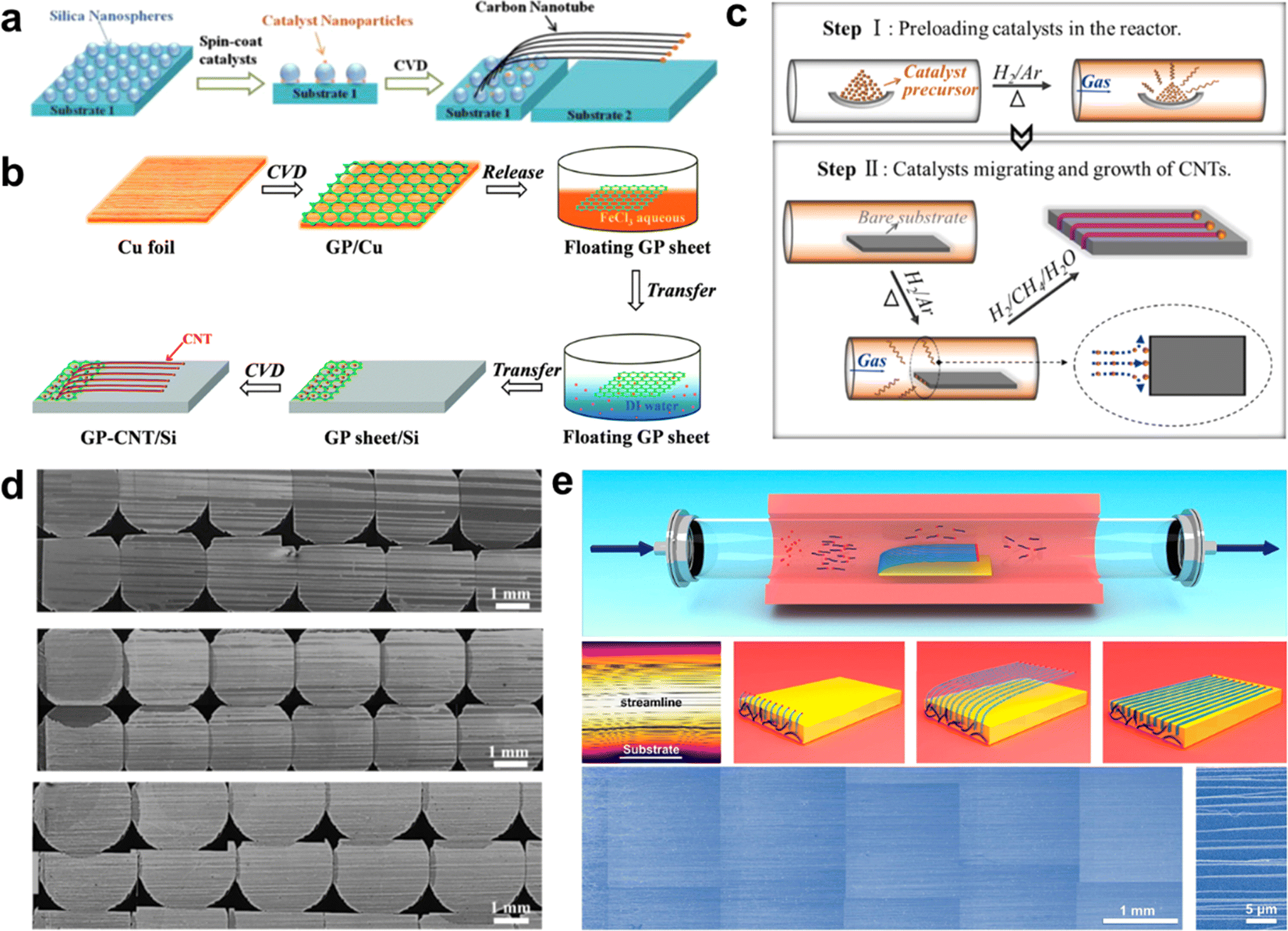 | ||
| Fig. 7 (a) Inhibition of catalyst particle aggregation and growth of high-density CNT horizontal arrays by silicon dioxide nanospheres.93 Reproduced from ref. 93 with permission from Elsevier Ltd., copyright 2013. (b) Graphene layer-loaded catalyst particles for growing horizontal arrays of CNTs.94 Reproduced from ref. 94 with permission from Royal Society of Chemistry, copyright 2014. (c) Schematic diagram of catalyst pre-deposition process. (d) SEM image of multiple growth of ultralong CNTs using a single-deposited catalyst.95 Reproduced from ref. 95 with permission from Elsevier Ltd., copyright 2016. (e) Synthesis of high-density ultralong CNT arrays by SIDS method.31 Reproduced from ref. 31 with permission from American Chemical Society, copyright 2023. | ||
The two methods mentioned above utilize the pinning effect of nanomaterials to improve the dispersion of catalyst nanoparticles, which in turn inhibits the aggregation of particles at high temperatures. However, these methods have not been able to address the issue of low catalyst utilization efficiency. Additionally, many short CNTs remain in the catalyst zone, which prevents the intrinsic improvement of ultralong CNTs array density.
Zhang et al. proposed a SIDS way to achieve high-yield preparation of ultralong CNTs (Fig. 7e).31 In this study, short CNTs in the gas phase were intercepted by a flat substrate placed inside the FCCVD device. The substrate edge splits the gas flow, immobilizing one end of the CNTs. Then, the CNTs floated up under the guidance of the gas flow and the lifting effect of the thermal buoyancy force, continuously growing into ultralong CNTs. This method efficiently couples FCCVD with the growth process of ultralong CNTs, resulting in a significant increase in the utilization efficiency of the catalyst. Additionally, the aggregation of catalyst nanoparticles was effectively suppressed, which led to a significant increase in the yield of ultralong CNTs. The researchers successfully produced ultralong CNTs with the highest array density of 6700 nanotubes per mm, which is 2–3 orders of magnitude higher than that of the conventional method. Moreover, the ultralong CNTs prepared by SIDS can reach lengths on the order of decimeters, with uniform and continuous morphology and high orientation. The TEM test shows that the ultralong CNTs have high crystallinity, clean surfaces, and low wall counts, confirming that the ultralong CNTs have very high crystallinity.
3.3. Control of the wall number and diameter of ultralong CNTs
The length index of ultralong CNTs is critical, but their structural control is equally important.7 This control includes ensuring the structural consistency of CNTs, controlling the number of tube walls, managing the diameter, and selecting the chirality. Among these factors, controlling the wall number and diameter of CNTs is achievable by changing the catalyst particle type, adjusting the catalyst size, regulating the growth temperature, altering the raw materials, and other similar methods.98–100Metal catalysts, such as iron, copper, and cobalt, are commonly used for the preparation of ultralong CNTs. Iron and copper catalysts are preferred due to their lower melting and boiling points, as well as weaker forces with silicon substrates, which make it easier to catalyze the growth of horizontal arrays of CNTs.104 Experiments and molecular dynamics simulations have shown that adjusting the surface energy of copper particles results in smaller and more uniformly distributed particles, leading to a smaller and more concentrated tube diameter distribution of CNTs formed from copper catalysts. Moreover, catalyst particle sizes can be controlled by adjusting the concentration of the catalyst precursor, allowing for selective distribution of tube diameters in horizontal arrays of CNTs. Hong et al. used different concentrations of FeCl3 solutions as the catalyst precursor to prepare horizontal arrays of single-walled CNTs (SWCNT) and multi-walled CNTs (MWCNT).105 However, catalyst particles tend to aggregate at high temperatures, so carrier materials are used to disperse the catalyst particles and reduce aggregation. Jiang et al. synthesized SWCNT horizontal arrays with a uniform diameter distribution by using a single layer of spinnable CNTs as the catalyst carrier, which prevented catalyst aggregation. The electrical properties of these CNTs were homogeneous and consistent over a length range. Additionally, oxide materials have been used as catalyst carriers. Li et al. used cerium oxide (CeO2) loaded with iron or cobalt nanoparticles to prepare semiconducting SWCNT horizontal arrays (Fig. 8a).106 CeO2 is stable at high temperatures and has an oxygen storage capacity, which allows for the etching of metal-type CNTs, resulting in highly selective semiconducting CNT arrays. CNTs created using this method have a narrow tube size distribution, and the proportion of semiconductor-type CNTs can reach over 93%.
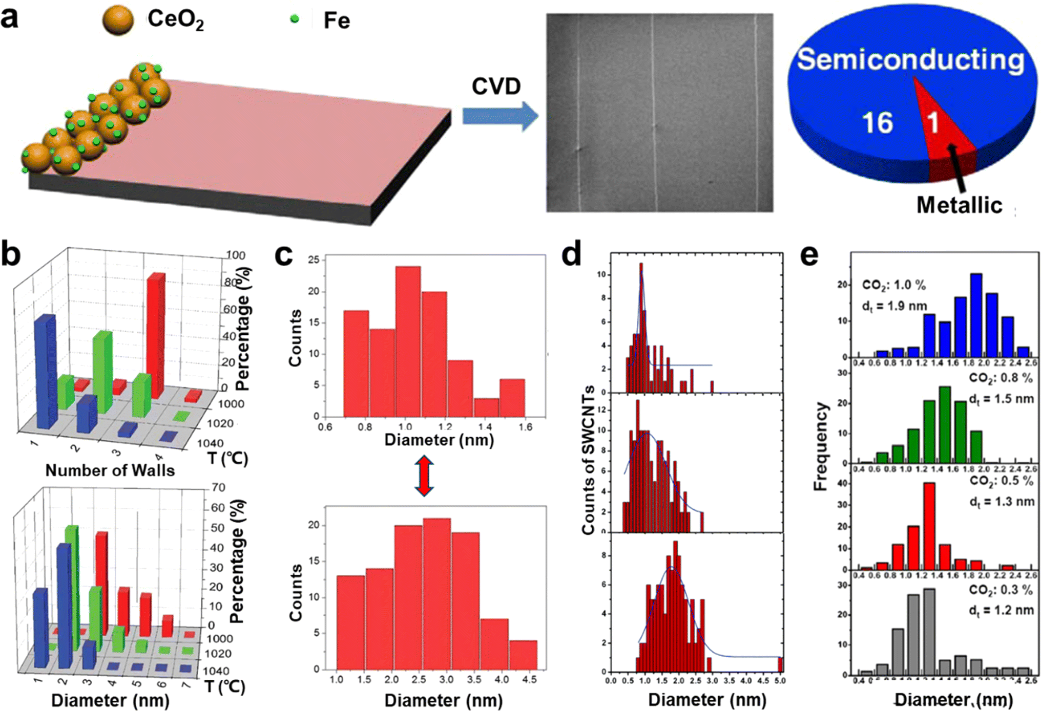 | ||
| Fig. 8 (a) Cerium oxide as a catalyst particle carrier for the preparation of highly selective semiconductor-type CNT horizontal arrays.106 Reproduced from ref. 106 with permission from American Chemical Society, copyright 2014. (b) Effect of temperature on wall number and diameter of CNTs.107 Reproduced from ref. 107 with permission from Wiley-VCH, copyright 2010. (c) Different carbon sources (up: CO gas, down: CH4 gas) lead to the growth of SWCNTs with different diameter distributions.108 Reproduced from ref. 108 with permission from Royal Society of Chemistry, copyright 2012. (d) Diameter distributions of SWCNTs grown at different ethane concentrations at 900 °C (up to down: 140 ppm, 1600 ppm, and 14400 ppm, respectively).109 Reproduced from ref. 109 with permission from American Chemical Society, copyright 2006. (e) The fitted diameter diagrams of the SWCNT samples as a function of CO2 concentration.110 Reproduced from ref. 110 with permission from Elsevier Ltd., copyright 2011. | ||
Zhang et al. researched the effect of temperature on the diameter of CNTs.111 They discovered that by changing the growth temperature during the process, it is possible to create intramolecular junctions between CNTs of different diameters. This work confirmed that the diameter of CNTs can be reduced by increasing the reaction temperature during growth. This happens because the carbon-solubilizing capacity of catalyst particles changes after the temperature increases, which affects their shape. The temperature change also impacts the interaction between CNTs and catalysts. Furthermore, increasing the temperature reduces the stiffness of the carbon layer, which makes it more favorable for the growth of small-diameter CNTs with high-strain energy.
3.4. Control of the morphology of ultralong CNTs
By altering the reactor configuration and reaction conditions, ultralong CNTs with different structures such as crossed CNT networks, CNT forests, and suspended CNT structures can be obtained.113,114 It is also necessary to adjust their morphology in a controllable way, except for the length, density, and diameter to meet their applications.Wei et al. have successfully developed a method to prepare long and continuous CNTBs that have a consistent structure and orientation (Fig. 9a–c).78 By using a gas-flow focusing technique, they were able to produce CNTBs of varying lengths and compositions. The researchers studied the mechanical properties of these CNTBs and found that the overall strength of the bundles was influenced by the “Daniel effect”. They discovered that the tensile strength of CNTBs can be increased to over 80 GPa by relaxing the initial stress of the CNTs using a “simultaneous relaxation and tension” strategy. This approach allowed the tensile strength of a bundle containing an unlimited number of ultralong CNTs to be close to that of a single nanotube, if the bundle was of continuous length, had a perfect structure and consistent orientation, and the initial stress was uniformly distributed. The promising findings of this study suggest that ultralong CNTs could be used to create super-strong fibers and provide a direction and methodology for the development of new types of super-strong fibers.17
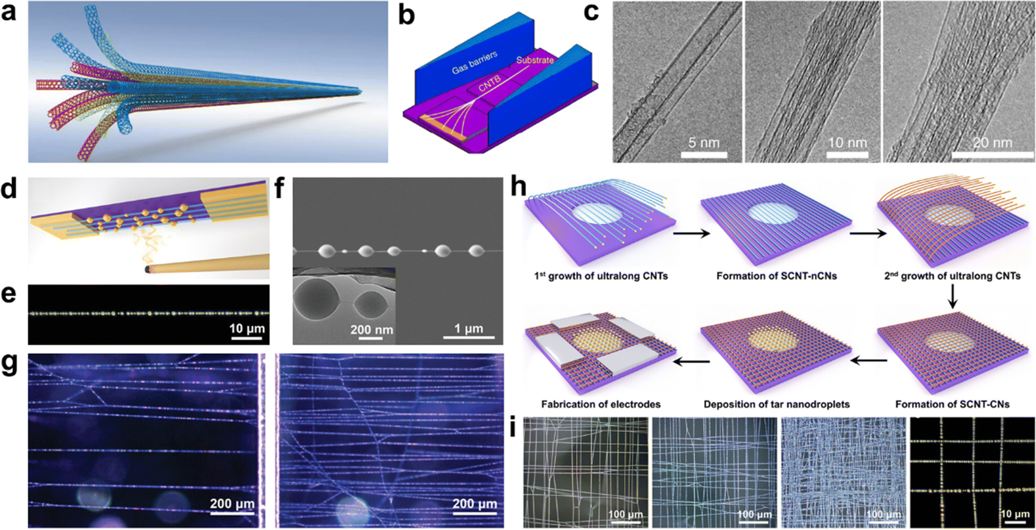 | ||
| Fig. 9 (a) Schematic illustration of ultralong CNTBs composed of continuous CNTs. (b) Schematic illustration of the in situ fabrication of CNTBs by the gas-flow focusing method. (c) TEM images of CNTBs with different component numbers.78 Reproduced from ref. 78 with permission from Springer Nature, copyright 2018. (d) Optical visualization diagram, (e) optical picture, and (f) SEM picture of a single SCNTN. (g) Optical microscopy images of SCNTNs with different areal densities.114 Reproduced from ref. 114 with permission from Wiley-VCH, copyright 2022. (h) Synthesis and (i) morphologies of SCNT-CNs.33 Reproduced from ref. 33 with permission from American Chemical Society, copyright 2024. | ||
4. Properties and applications of ultralong CNTs
The unique structures, huge aspect ratios, defect-free structures, and macroscopic lengths endow the ultralong CNTs with excellent properties and novel characteristics. Many studies have been conducted on the properties of ultralong CNTs which exhibited superior mechanical, electrical, and thermal performance.4.1. Extraordinary properties of ultralong CNTs
Ultralong CNTs possess remarkable mechanical properties including tensile strength above 100 GPa, Young's modulus above 1 TPa, and elongation at break of more than 17% (Fig. 10a and b).78 The ultralong CNTs exhibit a superior fatigue resistance, with the ability to withstand large-strain cyclic tensile tests without breaking (Fig. 10c and d).80 Furthermore, ultralong CNTs display high mobility and consistency in their electrical properties, as discovered by Fan et al.,86 and wide linear intervals of up to 120 dB in photodiodes, as observed by Peng et al.120 In terms of thermal properties, an extremely high heat transfer coefficient of approximately 8.9 × 10⁴ Wm−2 K−1 between a single suspended ultralong CNTs and air was also reported.79 Besides, Wei et al. also found the superlubrication in the centimeter-length CNTs in an atmospheric environment (Fig. 10e and f).119 The super-lubrication scale was three orders of magnitude higher than the highest value reported before. The friction between CNT layers was measured to be as low as 1–2 nN, which is 5–100 times better than previous experimental results. The shear strength obtained is 4 orders of magnitude lower than the lowest value of literature results and is independent of the length of the contact. This means that ultralong CNTs have the potential to provide a new material platform and perspective to study unique surface-interface phenomena at the nanoscale.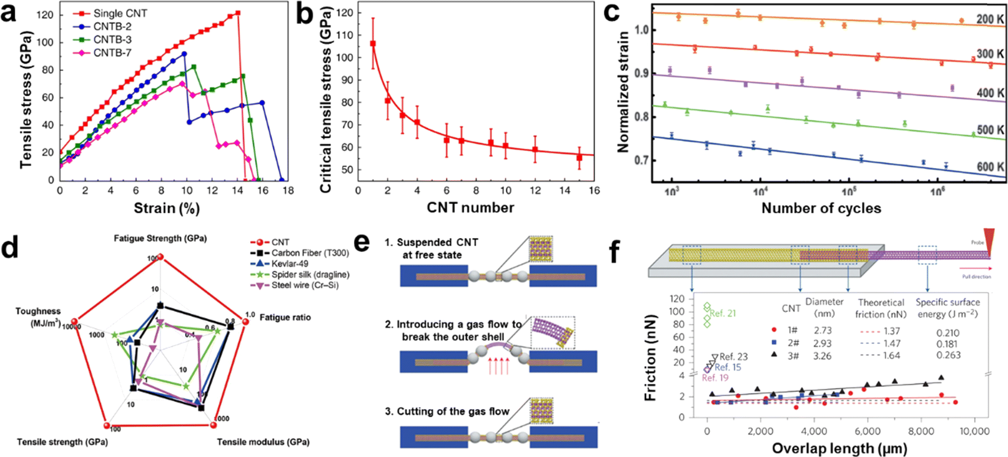 | ||
| Fig. 10 (a) Stress-strain curves for single CNTs and CNTBs with gauge lengths of about 1.5 mm. (b) The relationship between the tensile strength of CNTBs and the CNTB component numbers.78 Reproduced from ref. 78 with permission from Springer Nature, copyright 2018. (c) Fatigue behavior of CNTs at different temperatures. (d) Comparison of mechanical performance between CNTs and some high-performance materials.80 Reproduced from ref. 80 with permission from American Association for the Advancement of Science, copyright 2020. (e) Illustrations showing inner-shell sliding processes for ultralong DWCNTs. (f) Schematic of an inner shell being pulled out of a DWCNT and intershell friction of three DWCNTs with different outer diameters.119 Reproduced from ref. 119 with permission from Springer Nature, copyright 2013. | ||
4.2. Applications of ultralong CNTs
Ultralong CNTs are promising candidates for high-performance field-effect transistors (FETs). Ultralong CNTs have carrier mobility as high as 105 cm2 V−1 s−1 and an ultra-high saturation speed. Furthermore, CNTs can form ohmic contacts with specific metal electrodes to achieve ballistic transport, and are compatible with low-temperature semiconductor manufacturing processes, making them suitable for the construction of large-scale integrated circuits. Wei et al. synthesized high-density ultralong CNT arrays up to 65 cm long on multiple 4-inch wafers by utilizing catalyst pre-deposition and multiple growths (Fig. 11a).79 They constructed large-scale FET devices on these ultralong CNT arrays to characterize their electrical properties. The results showed that most of the FET devices exhibit high open-state currents, high switching ratios, and high mobility (Fig. 11b). Additionally, they introduced a certain frequency of acoustic waves during the growth of ultralong CNTs, which enabled the self-assembly of CNTs into CNT wire clusters. The obtained CNT assemblies have high open-state currents, which satisfy the application of CNTs in nanodevices. Zhang et al. successfully fabricated decimeter-scale ultralong CNTs with an array density of 6700 CNTs/mm using the SIDS method and produced large-scale arrays of FET devices.31 This work found that the switching ratio of the FET devices was generally elevated with the increase of the array length. In addition, the open-state current of the FET decreases slowly with the increase of the array length. These results indicated that the array density of ultralong CNTs decays gradually with the increase of the length, which is in good agreement with the Schulz–Flory distribution law of ultralong CNTs. This work takes advantage of the spontaneous purification behavior of ultralong CNTs to measure FET composed of pure semiconductor-type CNTs with switching ratios as high as 4.2 × 10⁵. All in all, these results demonstrate the potential of ultralong CNTs for application in high-performance FET devices.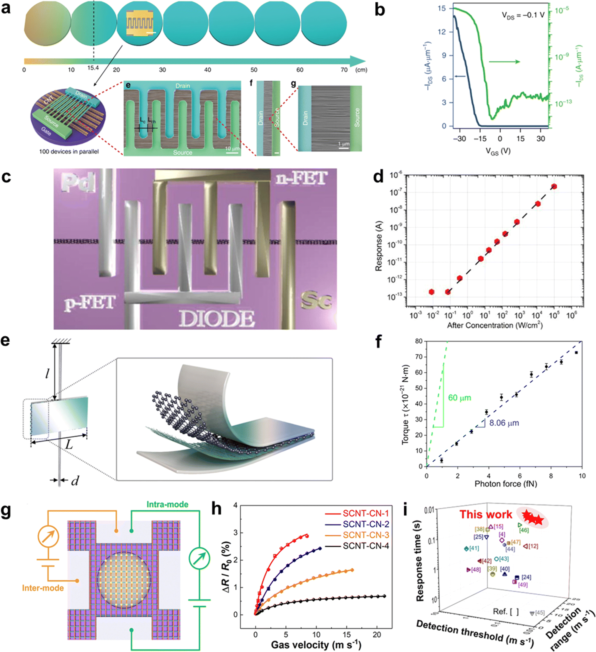 | ||
| Fig. 11 (a) FET devices based on ultralong CNT arrays. (b) Transfer characteristics of the width normalized transistor for a single channel plotted in both linear (blue, left axis) and logarithmic (green, right axis) scales with applied VDS of −0.1 V.79 Reproduced from ref. 79 with permission from Springer Nature, copyright 2019. (c) A 3D sketch of the device for high-frequency measurement. (d) The high-frequency response of the photodetector at 0 V.120 Reproduced from ref. 120 with permission from AIP Publishing LLC, copyright 2014. (e) Schematic illustration of the torsion balance unit. (f) Torque versus incident photon force.121 Reproduced from ref. 121 with permission from American Association for the Advancement of Science, copyright 2021. (g) Schematic illustration of the inter and intramode for the testing of SCNT-CNs-based airflow sensors. (h) Relative resistance variation of SCNT-CNs with different areal densities under different gas velocities. (i) Performance comparison between SCNT-CNs-based airflow sensors and previously reported airflow sensors.33 Reproduced from ref. 33 with permission from American Chemical Society, copyright 2024. | ||
CNTs are materials that have a direct bandgap and high absorption coefficients in a wide range of spectral frequencies, from ultraviolet to terahertz bands. The intrinsic response time of CNTs is very fast, on the order of 10−12 seconds. These properties make CNTs potentially useful for high-performance photodetectors, and they are expected to outperform conventional photodetector materials like InGaAs and HgCdTe under room-temperature operating conditions.122 However, there have been few studies on ultralong CNTs due to difficulties in preparing them efficiently. One study by Peng and Wang involved constructing Pd–Sc asymmetric fork-finger electrodes on a single ultralong CNT to create a diode-configured photodetector.122 The researchers found that when the laser power density ranged from 10−1 to 105 W cm−2, the response current of the device at zero bias showed perfect linear behavior, corresponding to a linear interval of 120 dB (Fig. 11c and d).120 The photocurrent reached up to 545.65 nA at 105 W cm−2 power density and optimal polarization. The authors attributed the wide linear interval to the ultralong CNT's high mobility, short channel length, high charge collection efficiency, and non-doped device preparation process.
Ultralong CNTs possess a high aspect ratio, high flexibility, and high modulus, which makes them highly responsive to external fields. When designed as suspended devices, they can be used to create mechanical sensors with high sensitivity. Jiang et al. recently developed a sandwich-structured torsion scale by utilizing the large aspect ratio and flexibility of ultralong CNTs (Fig. 11e and f).121 The scale consists of an aluminum membrane, a graphene-CNT membrane, and ultralong CNTs. A low-power laser was focused and irradiated onto the torsion scale, and even a weak light pressure could cause it to twist. The angle of torsion was measured by determining the displacement of the spot after the laser light was reflected by the aluminum membrane. The torsion scale can measure forces as low as 10−15 N with a torsional spring constant of only 8.72 × 10⁻¹⁸ N m rad−1 and a sensitivity of about 1013 rad N−1. This superior performance makes it an ideal option when compared to other materials.
Airflow sensors have very important applications in aerospace, weather forecasting, environmental monitoring, the chemical industry, biomedicine, health monitoring, and smart wearable devices.123 However, traditional airflow sensors have limitations such as slow response rate, low sensitivity, high detection limit, narrow detection range, and large hysteresis.124 These limitations hinder the sensor's applications in various fields. CNTs possess excellent mechanical and electrical properties, making them an ideal candidate for airflow sensors.114 However, in most current reports on airflow sensors, CNTs are usually combined with rigid matrix materials, which greatly limits their displacement and deformation under airflow trailing forces. This leads to poor sensitivity and response speed of the devices. Additionally, the reports often use multi-walled CNTs containing more defects, which further degrades the device's performance. Zhang et al. developed a high-performance airflow sensor using SCNTNs (Fig. 11g–i).33 They modified the nanoparticles on the surface of CNTs networks to achieve optical visualization, structural stability, and enhancement of airflow traction. The ultralight and extremely flexible structure of the ultralong SCNTN gave it superior sensing performance than most airflow sensors. The airflow sensor showed a very short response time (0.021 s), high sensitivity (0.0124 sm−1), low detection threshold (0.02 ms−1), and wide detection range (0.02–21 ms−1). The comprehensive performance of this sensor is significantly better than most current reports.
5. Summary and outlook
In this review, we discussed the growth mechanism, controlled synthesis, properties, and applications of ultralong CNTs. Ultralong CNTs have been widely investigated in recent years due to their perfect structures and excellent properties, while challenges remain, i.e., the structure-controlled synthesis and mass preparation of high-quality ultralong CNTs without structural defects. However, these challenges are also accompanied by potential opportunities for ultralong CNTs to be applied in more cutting-edge fields. Ultralong CNTs are preferred for preparing super-strong CNT fibers. Except for low defects, increasing the yield and reducing the cost are the keys to achieving the large-scale application of ultra-strong CNT fibers. Ensuring high performance while avoiding over-treatment is also important to be considered for producing super-strong and high-performance CNT fibers. Herein, we propose the following outlooks for the field of ultralong CNTs.Firstly, novel theoretical and experimental techniques are expected to be incorporated into studying growth mechanisms and synthetic methodologies. For example, deeper understandings of the growth mechanisms of ultralong CNTs may be anticipated using artificial intelligence (AI) and multiscale theoretical simulations. AI-assisted research may unveil the key factors hidden behind the growth behavior of ultralong CNTs, which can hardly be resolved under traditional research paradigms. Moreover, combining the electronic structures revealed by ab initio simulations, atomic and molecular structures revealed by molecular dynamics, and macroscale structures revealed by computational fluid dynamics, a complete vision of the growth mechanisms containing multiple spatiotemporal scales is expected to be established. In the aspects of experimental techniques, in situ characterization techniques may enable the collection of abundant information during the growth of ultralong CNTs. In situ Raman spectroscopy, TEM, and SEM characterizations can be combined with reactors to demonstrate the dynamic changes of multiple physical fields, establish the correlations between growth conditions and CNT structures, and facilitate the optimization of experimental protocols. Secondly, advanced techniques for the mass production of ultralong CNTs should be developed. The coupled processes of momentum transfer, heat transfer, mass transfer, and reactions are expected to be thoroughly investigated both in computational and experimental manners. Based on the fundamental growth mechanisms and scale-up principles, reactors with higher capabilities should be rationally designed and tested to further increase the yields and uniformity of ultralong CNT products. Finally, functionalization strategies need to be further developed for in situ modification or efficient compounding of ultralong CNTs, leading to the design of multi-functional, high-performance devices to fully exploit the ultimate properties of ultralong CNTs.
In summary, more effort is needed in the future. More investigations are required in developing large-scale synthesis techniques, studying special properties, and exploring new applications of ultralong CNTs.
Data availability
No primary research results, software or code have been included and no new data were generated or analysed as part of this review.Author contributions
Kangkang Wang: conceptualization, writing – original draft, writing – review & editing. Fei Wang: writing – original draft, writing – review & editing. Qinyuan Jiang: writing – review & editing. Ping Zhu: writing – review & editing. Khaixien Leu: writing – review & editing. Rufan Zhang: supervision, project administration, funding acquisition, writing – review & editing. All authors have given approval to the final version of the manuscript.Conflicts of interest
There are no conflicts to declare.Acknowledgements
This work is supported by the National Key Research and Development Program (Grant No. 2020YFC2201103 and 2020YFA0210702) and National Natural Science Foundation of China (Grant No. 51872156 and 22075163).References
- T. O. Wehling, A. M. Black-Schaffer and A. V. Balatsky, Adv. Phys., 2014, 63, 1–76 CrossRef CAS.
- S. Ghosh, S. Barg, S. M. Jeong and K. K. Ostrikov, Adv. Energy Mater., 2020, 10, 2001239 CrossRef CAS.
- K. D. Patel, R. K. Singh and H.-W. Kim, Mater. Horiz., 2019, 6, 434–469 RSC.
- D.-M. Sun, M. Y. Timmermans, A. Kaskela, A. G. Nasibulin, S. Kishimoto, T. Mizutani, E. I. Kauppinen and Y. Ohno, Nat. Commun., 2013, 4, 2302 CrossRef PubMed.
- S. Chen, L. Qiu and H.-M. Cheng, Chem. Rev., 2020, 120, 2811–2878 CrossRef CAS PubMed.
- T. Chen and L. Dai, J. Mater. Chem. A, 2014, 2, 10756–10775 RSC.
- R. Zhang, Y. Zhang and F. Wei, Chem. Soc. Rev., 2017, 46, 3661–3715 RSC.
- R. Li, Q. Jiang and R. Zhang, Sci. Bull., 2022, 67, 784–787 CrossRef CAS PubMed.
- R. Zhang, Q. Wen, W. Qian, D. S. Su, Q. Zhang and F. Wei, Adv. Mater., 2011, 23, 3387–3391 CrossRef CAS PubMed.
- K. Chen, W. Gao, S. Emaminejad, D. Kiriya, H. Ota, H. Y. Y. Nyein, K. Takei and A. Javey, Adv. Mater., 2016, 28, 4397–4414 CrossRef CAS PubMed.
- Y. Zhan, R. Zhao, Y. Lei, F. Meng, J. Zhong and X. Liu, Appl. Surf. Sci., 2011, 257, 4524–4528 CrossRef CAS.
- C. Rutherglen and P. Burke, Small, 2009, 5, 884–906 CrossRef CAS PubMed.
- B. D. Jensen, J.-W. Kim, G. Sauti, K. E. Wise, J. M. Gardner, J. G. Smith, R. A. Wincheski, R. J. Cano and E. J. Siochi, ACS Appl. Nano Mater., 2023, 6, 9558–9568 CrossRef CAS.
- D. Yu, K. Goh, H. Wang, L. Wei, W. Jiang, Q. Zhang, L. Dai and Y. Chen, Nat. Nanotechnol., 2014, 9, 555–562 CrossRef CAS PubMed.
- N. M. Bandaru and N. H. Voelcker, J. Mater. Chem., 2012, 22, 8748–8758 RSC.
- J. Sun, Z. Zhao, Z. Li, Z. Zhang, R. Zhang and X. Meng, J. Mater. Chem. A, 2023, 11, 22430–22440 RSC.
- R. Zhang, Y. Zhang and F. Wei, Acc. Chem. Res., 2017, 50, 179–189 CrossRef CAS PubMed.
- N. Saito, Y. Usui, K. Aoki, N. Narita, M. Shimizu, K. Hara, N. Ogiwara, K. Nakamura, N. Ishigaki, H. Kato, S. Taruta and M. Endo, Chem. Soc. Rev., 2009, 38, 1897–1903 RSC.
- Y. Zhao, R. Li, B. Wang, Y. Huang, P. Lyu, F. Wang, Q. Jiang, Y. Han, S. Zhang, X. Wu, S. Zhao, N. Zhu and R. Zhang, ACS Nano, 2023, 17, 2893–2900 CrossRef CAS PubMed.
- R. Li, S. Zhang, H. Chen, Y. Huang, B. Wang, X. Wu, Q. Jiang, S. Zhao, F. Wang, Y. Zhao and R. Zhang, SusMat, 2023, 3, 102–110 CrossRef CAS.
- F. Wang, S. Zhao, Q. Jiang, R. Li, Y. Zhao, Y. Huang, X. Wu, B. Wang and R. Zhang, Cell Rep. Phys. Sci., 2022, 3, 100989 CrossRef CAS.
- S. Muhl, R. Aguilar Osorio and U. A. Martinez Huitle, Rev. Mex. Fis., 2017, 63, 439–447 Search PubMed.
- D. Janas, S. Boncel and K. K. K. Koziol, Carbon, 2014, 73, 259–266 CrossRef CAS.
- Y. Liu and S. Kumar, ACS Appl. Mater. Interfaces, 2014, 6, 6069–6087 CrossRef CAS PubMed.
- J. Si, L. Liu, F. Wang, Z. Zhang and L.-M. Peng, ACS Nano, 2016, 10, 6737–6743 CrossRef CAS PubMed.
- C. Wang, J.-C. Chien, K. Takei, T. Takahashi, J. Nah, A. M. Niknejad and A. Javey, Nano Lett., 2012, 12, 1527–1533 CrossRef CAS PubMed.
- M. Endo, T. Hayashi and Y.-A. Kim, Pure Appl. Chem., 2006, 78, 1703–1713 CrossRef CAS.
- J. Ma, Z. Zhu, B. Chen, M. Yang, H. Zhou, C. Li, F. Yu and J. Chen, J. Mater. Chem. A, 2013, 1, 4662–4666 RSC.
- Q. Ye, A. M. Cassell, H. B. Liu, K. J. Chao, J. Han and M. Meyyappan, Nano Lett., 2004, 4, 1301–1308 CrossRef CAS.
- Q. Jiang, F. Wang, R. Li, X. Wu, W. Zhang, S. Zhao, Y. Huang, B. Wang, S. Zhang, Y. Zhao and R. Zhang, Adv. Funct. Mater., 2023, 33, 2212665 CrossRef CAS.
- Q. Jiang, F. Wang, R. Li, B. Li, N. Wei, N. Gao, H. Xu, S. Zhao, Y. Huang, B. Wang, W. Zhang, X. Wu, S. Zhang, Y. Zhao, E. Shi and R. Zhang, Nano Lett., 2023, 23, 523–532 CrossRef CAS PubMed.
- F. Chen, Y. Huang, R. Li, S. Zhang, Q. Jiang, Y. Luo, B. Wang, W. Zhang, X. Wu, F. Wang, P. Lyu, S. Zhao, W. Xu, F. Wei and R. Zhang, Sci. Adv., 2022, 8, eabn5882 CrossRef CAS PubMed.
- Q. Jiang, K. Leu, X. Gong, F. Wang, R. Li, K. Wang, P. Zhu, Y. Zhao, Y. Zang and R. Zhang, ACS Appl. Mater. Interfaces, 2024, 16, 20949–20958 CAS.
- X. K. Wang, X. W. Lin, V. P. Dravid, J. B. Ketterson and R. P. H. Chang, Appl. Phys. Lett., 1995, 66, 2430–2432 CrossRef CAS.
- Y. Wang, Q. Zhang, Z. Liu, R. Huang and L. Zheng, Acta Phys.-Chim. Sin., 1996, 12, 905–909 CAS.
- K. A. Shah and B. A. Tali, Mater. Sci. Semicond. Process., 2016, 41, 67–82 CrossRef CAS.
- J. Robertson, G. Zhong, S. Esconjauregui, C. Zhang, M. Fouquet and S. Hofmann, Phys. Status Solidi B, 2012, 249, 2315–2322 CrossRef CAS.
- M. Jung, K. Y. Eun, J. K. Lee, Y. J. Baik, K. R. Lee and J. W. Park, Diamond Relat. Mater., 2001, 10, 1235–1240 CrossRef CAS.
- I. Stassen, M. Styles, G. Grenci, H. Van Gorp, W. Vanderlinden, S. De Feyter, P. Falcaro, D. De Vos, P. Vereecken and R. Ameloot, Nat. Mater., 2016, 15, 304–310 CrossRef CAS PubMed.
- B. Liu, L. Chen, G. Liu, A. N. Abbas, M. Fathi and C. Zhou, ACS Nano, 2014, 8, 5304–5314 CrossRef CAS PubMed.
- R. M. Silva, M. C. Ferro, J. R. Araujo, C. A. Achete, G. Cavel, R. F. Silva and N. Pinna, Langmuir, 2016, 32, 7038–7044 CrossRef CAS PubMed.
- F. Beuneu, Solid State Commun., 2005, 136, 462–465 CrossRef CAS.
- M. He, H. Amara, H. Jiang, J. Hassinen, C. Bichara, R. H. A. Ras, J. Lehtonen, E. I. Kauppinen and A. Loiseau, Nanoscale, 2015, 7, 20284–20289 RSC.
- F. Ding, K. Bolton and A. Rosén, J. Phys. Chem. B, 2004, 108, 17369–17377 CrossRef CAS.
- F. Ding, K. Bolton and A. Rosén, Comput. Mater. Sci., 2006, 35, 243–246 CrossRef CAS.
- Q. Jin, S. Jiang, Y. Zhao, D. Wang, J. Qiu, D.-M. Tang, J. Tan, D.-M. Sun, P.-X. Hou, X.-Q. Chen, K. Tai, N. Gao, C. Liu, H.-M. Cheng and X. Jiang, Nat. Mater., 2019, 18, 62–68 CrossRef CAS PubMed.
- Y. Ohta, Y. Okamoto, S. Irle and K. Morokuma, ACS Nano, 2008, 2, 1437–1444 CrossRef CAS PubMed.
- Y. Ohta, Y. Okamoto, S. Irle and K. Morokuma, Carbon, 2009, 47, 1270–1275 CrossRef CAS.
- J. C. Charlier, A. DeVita, X. Blase and R. Car, Science, 1997, 275, 646–649 CrossRef CAS PubMed.
- R. Brukh and S. Mitra, Chem. Phys. Lett., 2006, 424, 126–132 CrossRef CAS.
- J. P. O'Byrne, Z. Li, S. L. T. Jones, P. G. Fleming, J. A. Larsson, M. A. Morris and J. D. Holmes, ChemPhysChem, 2011, 12, 2995–3001 CrossRef PubMed.
- J. Gavillet, A. Loiseau, C. Journet, F. Willaime, F. Ducastelle and J. C. Charlier, Phys. Rev. Lett., 2001, 87, 275504 CrossRef CAS PubMed.
- R. Wang, J. Li and Y. Wang, J. Phys. Chem. C, 2024, 128, 5112–5119 CrossRef CAS.
- P. J. F. Harris, Carbon, 2007, 45, 229–239 CrossRef CAS.
- Z. Li, L. Deng, I. A. Kinloch and R. J. Young, Prog. Mater. Sci., 2023, 135, 101089 CrossRef CAS.
- M. He, S. Zhang, Q. Wu, H. Xue, B. Xin, D. Wang and J. Zhang, Adv. Mater., 2019, 31, 1800805 CrossRef PubMed.
- Z. Jin, H. Chu, J. Wang, J. Hong, W. Tan and Y. Li, Nano Lett., 2007, 7, 2073–2079 CrossRef CAS PubMed.
- S. Han, X. L. Liu and C. W. Zhou, J. Am. Chem. Soc., 2005, 127, 5294–5295 CrossRef CAS PubMed.
- M. S. He, X. J. Duan, X. Wang, J. Zhang, Z. F. Liu and C. Robinson, J. Phys. Chem. B, 2004, 108, 12665–12668 CrossRef CAS.
- M. Saeidi, J. Cryst. Growth, 2014, 404, 34–38 CrossRef CAS.
- H. Shahrokhabadi, M. Saeidi, M. Vaezzadeh, H. Shahivandi and M. Salehian, J. Cryst. Growth, 2013, 371, 56–59 CrossRef CAS.
- H. Yoshida, S. Takeda, T. Uchiyama, H. Kohno and Y. Homma, Nano Lett., 2008, 8, 2082–2086 CrossRef CAS PubMed.
- H. Ago, N. Ishigami, N. Yoshihara, K. Imamoto, S. Akita, K.-i. Ikeda, M. Tsuji, T. Ikuta and K. Takahashi, J. Phys. Chem. C, 2008, 112, 1735–1738 CrossRef CAS.
- S. M. Huang, M. Woodson, R. Smalley and J. Liu, Nano Lett., 2004, 4, 1025–1028 CrossRef CAS.
- A. Gohier, C. P. Ewels, T. M. Minea and M. A. Djouadi, Carbon, 2008, 46, 1331–1338 CrossRef CAS.
- Y. J. Tian, Z. Hu, Y. Yang, X. Z. Wang, X. Chen, H. Xu, Q. Wu, W. J. Ji and Y. Chen, J. Am. Chem. Soc., 2004, 126, 1180–1183 CrossRef CAS PubMed.
- Y. Wang, X. Gao, H.-J. Qian, Y. Ohta, X. Wu, G. Eres, K. Morokuma and S. Irle, Carbon, 2014, 72, 22–37 CrossRef CAS.
- J. C. Charlier, H. Amara and P. Lambin, ACS Nano, 2007, 1, 202–207 CrossRef CAS PubMed.
- W. Zhou, Z. Han, J. Wang, Y. Zhang, Z. Jin, X. Sun, Y. Zhang, C. Yan and Y. Li, Nano Lett., 2006, 6, 2987–2990 CrossRef CAS PubMed.
- M. He, T. Yang, D. Shang, B. Xin, A. I. Chernov, E. D. Obraztsova, J. Sainio, N. Wei, H. Cui, H. Jiang and E. Kauppinen, Chem. Eng. J., 2018, 341, 344–350 CrossRef CAS.
- M. Saeidi, Phys. E, 2015, 70, 225–230 CrossRef CAS.
- Y. Hu, L. Kang, Q. Zhao, H. Zhong, S. Zhang, L. Yang, Z. Wang, J. Lin, Q. Li, Z. Zhang, L. Peng, Z. Liu and J. Zhang, Nat. Commun., 2015, 6, 6099 CrossRef CAS PubMed.
- L. Kang, S. Zhang, Q. Li and J. Zhang, J. Am. Chem. Soc., 2016, 138, 6727–6730 CrossRef CAS PubMed.
- L. Ding, A. Tselev, J. Wang, D. Yuan, H. Chu, T. P. McNicholas, Y. Li and J. Liu, Nano Lett., 2009, 9, 800–805 CrossRef CAS PubMed.
- Y. Chen, Y. Hu, Y. Fang, P. Li, C. Feng and J. Zhang, Carbon, 2012, 50, 3295–3297 CrossRef CAS.
- L. X. Zheng, M. J. O'Connell, S. K. Doorn, X. Z. Liao, Y. H. Zhao, E. A. Akhadov, M. A. Hoffbauer, B. J. Roop, Q. X. Jia, R. C. Dye, D. E. Peterson, S. M. Huang, J. Liu and Y. T. Zhu, Nat. Mater., 2004, 3, 673–676 CrossRef CAS PubMed.
- S. Zhang, L. Kang, X. Wang, L. Tong, L. Yang, Z. Wang, K. Qi, S. Deng, Q. Li, X. Bai, F. Ding and J. Zhang, Nature, 2017, 543, 234–238 CrossRef CAS PubMed.
- Y. Bai, R. Zhang, X. Ye, Z. Zhu, H. Xie, B. Shen, D. Cai, B. Liu, C. Zhang, Z. Jia, S. Zhang, X. Li and F. Wei, Nat. Nanotechnol., 2018, 13, 589–595 CrossRef CAS PubMed.
- Z. Zhu, N. Wei, W. Cheng, B. Shen, S. Sun, J. Gao, Q. Wen, R. Zhang, J. Xu, Y. Wang and F. Wei, Nat. Commun., 2019, 10, 4467 CrossRef PubMed.
- Y. Bai, H. Yue, J. Wang, B. Shen, S. Wang, H. Wang, X. Li, Z. Xu, R. Zhang and F. Wei, Science, 2020, 369, 1104–1106 CrossRef CAS PubMed.
- Z. Zhu, N. Wei, B. Yan, B. Shen, J. Gao, S. Sun, H. Xie, H. Xiong, C. Zhang, R. Zhang, W. Qian, S. Fu, L. Peng and F. Wei, ACS Nano, 2021, 15, 5129–5137 CrossRef CAS PubMed.
- Q. Wen, R. Zhang, W. Qian, Y. Wang, P. Tan, J. Nie and F. Wei, Chem. Mater., 2010, 22, 1294–1296 CrossRef CAS.
- B. Peng, Y. Yao and J. Zhang, J. Phys. Chem. C, 2010, 114, 12960–12965 CrossRef CAS.
- R. Zhang, Y. Zhang, Q. Zhang, H. Xie, W. Qian and F. Wei, ACS Nano, 2013, 7, 6156–6161 CrossRef CAS PubMed.
- P. J. Flory, J. Am. Chem. Soc., 1936, 58, 1877–1885 CrossRef CAS.
- X. Wang, Q. Li, J. Xie, Z. Jin, J. Wang, Y. Li, K. Jiang and S. Fan, Nano Lett., 2009, 9, 3137–3141 CrossRef CAS PubMed.
- T. Inoue, D. Hasegawa, S. Badar, S. Aikawa, S. Chiashi and S. Maruyama, J. Phys. Chem. C, 2013, 117, 11804–11810 CrossRef CAS.
- J. R. Sanchez-Valencia, T. Dienel, O. Groening, I. Shorubalko, A. Mueller, M. Jansen, K. Amsharov, P. Ruffieux and R. Fasel, Nature, 2014, 512, 61–64 CrossRef CAS PubMed.
- L. Zhu, J. Wang and F. Ding, ACS Nano, 2016, 10, 6410–6415 CrossRef CAS PubMed.
- G. S. Tulevski, A. D. Franklin, D. Frank, J. M. Lobez, Q. Cao, H. Park, A. Afzali, S.-J. Han, J. B. Hannon and W. Haensch, ACS Nano, 2014, 8, 8730–8745 CrossRef CAS PubMed.
- Q. Wang, M.-F. Ng, S.-W. Yang, Y. Yang and Y. Chen, ACS Nano, 2010, 4, 939–946 CrossRef CAS PubMed.
- Y. Xie, L. Qian, D. Lin, Y. Yu, S. Wang and J. Zhang, Angew. Chem., Int. Ed., 2021, 60, 9330–9333 CrossRef CAS PubMed.
- H. Xie, R. Zhang, Y. Zhang, P. Li, Y. Jin and F. Wei, Carbon, 2013, 52, 535–540 CrossRef CAS.
- H. Xie, R. Zhang, Y. Zhang, W. Zhang, M. Jian, C. Wang, Q. Wang and F. Wei, Chem. Commun., 2014, 50, 11158–11161 RSC.
- H. Xie, R. Zhang, Y. Zhang, Z. Yin, M. Jian and F. Wei, Carbon, 2016, 98, 157–161 CrossRef CAS.
- P.-X. Hou, F. Zhang, L. Zhang, C. Liu and H.-M. Cheng, Adv. Funct. Mater., 2022, 32, 2108541 CrossRef CAS.
- A. G. Nasibulin, A. Kaskela, K. Mustonen, A. S. Anisimov, V. Ruiz, S. Kivisto, S. Rackauskas, M. Y. Timmermans, M. Pudas, B. Aitchison, M. Kauppinen, D. P. Brown, O. G. Okhotnikov and E. I. Kauppinen, ACS Nano, 2011, 5, 3214–3221 CrossRef CAS PubMed.
- L. Ding, W. Zhou, H. Chu, Z. Jin, Y. Zhang and Y. Li, Chem. Mater., 2006, 18, 4109–4114 CrossRef CAS.
- Y. Chen, D. Ciuparu, S. Lim, Y. H. Yang, G. L. Haller and L. Pfefferle, J. Catal., 2004, 226, 351–362 CrossRef CAS.
- D. B. Geohegan, A. A. Puretzky, J. J. Jackson, C. M. Rouleau, G. Eres and K. L. More, ACS Nano, 2011, 5, 8311–8321 CrossRef CAS PubMed.
- X. Liu and L. Dai, Nat. Rev. Mater., 2016, 1, 16064 CrossRef CAS.
- T. Y. Ma, S. Dai, M. Jaroniec and S. Z. Qiao, Angew. Chem., Int. Ed., 2014, 53, 7281–7285 CrossRef CAS PubMed.
- X. Lu, W.-L. Yim, B. H. R. Suryanto and C. Zhao, J. Am. Chem. Soc., 2015, 137, 2901–2907 CrossRef CAS PubMed.
- R. Cui, Y. Zhang, J. Wang, W. Zhou and Y. Li, J. Phys. Chem. C, 2010, 114, 15547–15552 CrossRef CAS.
- B. H. Hong, J. Y. Lee, T. Beetz, Y. M. Zhu, P. Kim and K. S. Kim, J. Am. Chem. Soc., 2005, 127, 15336–15337 CrossRef CAS PubMed.
- X. Qin, F. Peng, F. Yang, X. He, H. Huang, D. Luo, J. Yang, S. Wang, H. Liu, L. Peng and Y. Li, Nano Lett., 2014, 14, 512–517 CrossRef CAS PubMed.
- Q. Wen, W. Qian, J. Nie, A. Cao, G. Ning, Y. Wang, L. Hu, Q. Zhang, J. Huang and F. Wei, Adv. Mater., 2010, 22, 1867–1871 CrossRef CAS PubMed.
- M. He, H. Jiang, E. I. Kauppinen and J. Lehtonen, Nanoscale, 2012, 4, 7394–7398 RSC.
- C. Lu and J. Liu, J. Phys. Chem. B, 2006, 110, 20254–20257 CrossRef CAS PubMed.
- Y. Tian, M. Y. Timmermans, M. Partanen, A. G. Nasibulin, H. Jiang, Z. Zhu and E. I. Kauppinen, Carbon, 2011, 49, 4636–4643 CrossRef CAS.
- Y. Yao, Q. Li, J. Zhang, R. Liu, L. Jiao, Y. T. Zhu and Z. Liu, Nat. Mater., 2007, 6, 283–286 CrossRef CAS PubMed.
- Y. Tian, M. Y. Timmermans, S. Kivisto, A. G. Nasibulin, Z. Zhu, H. Jiang, O. G. Okhotnikov and E. I. Kauppinen, Nano Res., 2011, 4, 807–815 CrossRef CAS.
- A. Bsoul, M. S. M. Ali and K. Takahata, Electron. Lett., 2011, 47, 807–U894 CrossRef CAS.
- Q. Jiang, R. Li, F. Wang, X. Shi, F. Chen, Y. Huang, B. Wang, W. Zhang, X. Wu, F. Wei and R. Zhang, Adv. Mater., 2022, 34, 2107062 CrossRef CAS PubMed.
- A.-L. Wang, X.-J. He, X.-F. Lu, H. Xu, Y.-X. Tong and G.-R. Li, Angew. Chem., Int. Ed., 2015, 54, 3669–3673 CrossRef CAS PubMed.
- C. Wu, F. Li, Y. Zhang and T. Guo, Appl. Surf. Sci., 2013, 273, 432–436 CrossRef CAS.
- X. Shi, S. Zhao, F. Wang, Q. Jiang, C. Zhan, R. Li and R. Zhang, Nanoscale Adv., 2021, 3, 889–903 RSC.
- R. Li, Q. Jiang, F. Wang, X. Shi, F. Chen, Y. Huang, B. Wang, W. Zhang, X. Wu, F. Wei and R. Zhang, Small Methods, 2022, 6, 2101333 CrossRef CAS PubMed.
- R. Zhang, Z. Ning, Y. Zhang, Q. Zheng, Q. Chen, H. Xie, Q. Zhang, W. Qian and F. Wei, Nat. Nanotechnol., 2013, 8, 912–916 CrossRef CAS PubMed.
- N. Wei, Y. Liu, H. Xie, F. Wei, S. Wang and L.-M. Peng, Appl. Phys. Lett., 2014, 105, 073107 CrossRef.
- L. Cong, Z. Yuan, Z. Bai, X. Wang, W. Zhao, X. Gao, X. Hu, P. Liu, W. Guo, Q. Li, S. Fan and K. Jiang, Sci. Adv., 2021, 7, eabd2358 CrossRef CAS PubMed.
- Y. Liu, N. Wei, Q. Zeng, J. Han, H. Huang, D. Zhong, F. Wang, L. Ding, J. Xia, H. Xu, Z. Ma, S. Qiu, Q. Li, X. Liang, Z. Zhang, S. Wang and L.-M. Peng, Adv. Opt. Mater., 2016, 4, 238–245 CrossRef CAS.
- H. Guo, J. Chen, L. Tian, Q. Leng, Y. Xi and C. Hu, ACS Appl. Mater. Interfaces, 2014, 6, 17184–17189 CrossRef CAS PubMed.
- L. Huang, Y. Liu, G. Li, Y. Song, J. Su, L. Cheng, W. Guo, G. Zhao, H. Shen, Z. Yan, B. Z. Tang and R. Ye, Nano Lett., 2023, 23, 597–605 CrossRef CAS PubMed.
| This journal is © The Royal Society of Chemistry 2024 |