
 Open Access Article
 This Open Access Article is licensed under a Creative Commons Attribution-Non Commercial 3.0 Unported Licence
Au-decorated Sb2Se3 photocathodes for solar-driven CO2 reduction†
John Mark Christian M.
Dela Cruz
 a,
Ádám
Balog
a,
Péter S.
Tóth
a,
Gábor
Bencsik
a,
Gergely F.
Samu
ab and
Csaba
Janáky
*ab
a,
Ádám
Balog
a,
Péter S.
Tóth
a,
Gábor
Bencsik
a,
Gergely F.
Samu
ab and
Csaba
Janáky
*ab
aDepartment of Physical Chemistry and Materials Science, Interdisciplinary Excellence Centre, University of Szeged, Aradi Square 1, Szeged, H-6720, Hungary. E-mail: janaky@chem.u-szeged.hu
bELI ALPS, ELI-HU Non-Profit Ltd., Wolfgang Sandner Street 3, Szeged, H-6728, Hungary
First published on 16th January 2024
Abstract
Photoelectrodes with FTO/Au/Sb2Se3/TiO2/Au architecture were studied in photoelectrochemical CO2 reduction reaction (PEC CO2RR). The preparation is based on a simple spin coating technique, where nanorod-like structures were obtained for Sb2Se3, as confirmed by SEM images. A thin conformal layer of TiO2 was coated on the Sb2Se3 nanorods via ALD, which acted as both an electron transfer layer and a protective coating. Au nanoparticles were deposited as co-catalysts via photo-assisted electrodeposition at different applied potentials to control their growth and morphology. The use of such architectures has not been explored in CO2RR yet. The photoelectrochemical performance for CO2RR was investigated with different Au catalyst loadings. A photocurrent density of ∼7.5 mA cm−2 at −0.57 V vs. RHE for syngas generation was achieved, with an average Faradaic efficiency of 25 ± 6% for CO and 63 ± 12% for H2. The presented results point toward the use of Sb2Se3-based photoelectrodes in solar CO2 conversion applications.
Broader contextDirect photoelectrochemical (PEC) CO2 reduction offers an alternative pathway for producing chemicals by directly integrating the light absorption and CO2 conversion in one device. Most devices use In-based and Ga-based semiconductors, which might be a potential hurdle to technological development because of the scarcity and expensiveness of these materials. In direct PEC water splitting, Sb2Se3 has gained attention due to its interesting properties and the simplicity of its fabrication via spin coating. We have shown that an FTO/Au/Sb2Se3/TiO2 architecture can be utilized for direct photoelectrochemical CO2 reduction using Au nanoparticles as cocatalyst. We found that the final architecture displayed a three times increase in current density and an earlier onset potential as compared to Au foil in dark CO2 electroreduction. The product distribution showed a syngas mixture of CO and H2. The results obtained suggest a favorable research direction towards exploring existing architectures for direct PEC CO2 conversion studies. |
Introduction
Photoelectrochemical (PEC) hydrogen evolution (HER) and CO2 reduction (CO2RR) are promising routes for the production of alternative fuels (e.g., hydrogen, methanol, methane) to replace fossil fuels. Simultaneously, the utilization of solar fuels allows society to move a step closer to the decarbonization of various industrial processes and the energy sector. Direct PEC fuel generation, in theory, offers lower overall material cost compared to systems based on electrolyzers coupled to photovoltaic panels (PV-EC).1 In the former case, the integration of the light absorber and the particular redox reaction is achieved in a single system, making the use of wires and AC/DC converters unnecessary.1 As there is direct contact between the light absorber and the electrolyte in PEC configuration, thermal effects can also play a role in determining the rate of electrochemical reactions.2 The technological readiness level of direct PEC fuel generation is still low3,4 because: (i) the direct light absorber/electrolyte interface makes these systems prone to corrosion, and necessitates the use of protection layers, (ii) up to this point there is no “wonder material” that can integrate all required functionalities (e.g., efficient light absorption, carrier transport, product generation) of the photoelectrode.1Sb2Se3 has gained significant attention in the PEC community as a photoabsorber especially in HER related applications because of its favorable band positions.5–9 It is a p-type semiconductor, which has a bandgap between 1.1 and 1.3 eV,10 similar to that of Si. It has only a single stable phase, which eliminates the possibility of secondary phase formation.11,12 Sb2Se3 can be synthesized through simple solution-based methods (e.g., spin coating).5,13 Aside from solution processing, other common synthesis methods of this material are vapor transport deposition,14 close-space sublimation,15 thermal evaporation,16 sputtering,17 electrodeposition,18,19 and selenization of Sb thin films.20 Solution processing offers advantage in its simplicity and high throughput in preparing large area films. Nanostructured photoabsorbers provide better light absorption than planar films, because of lower reflection losses.21 A simple spin coating technique can be used to combine these two merits to produce high quality Sb2Se3 for PEC applications.
TiO2 has been widely explored as a protective coating,20–23 because of its stability in a wide pH range (as supported by its Pourbaix diagram).24 Additionally, it also functions as an electron transport layer that promotes the formation of a p–n junction22 when combined with a p-type semiconductor such as Sb2Se3. This dual functionality of TiO2 makes it an ideal material to pair with Sb2Se3 in fabricating a photocathode. However, making a conformal coating of TiO2 especially at the nanoscale is challenging. Atomic layer deposition (ALD) can deliver this specific requirement, without compromising the nano-morphology of the Sb2Se3. In spite of this conformality, the drawback of this specific type of TiO2 is its lack of stability during long-term measurements.25 Electron accumulation at the surface of the thin TiO2 layer was shown to trigger the dissolution of the protective TiO2 layer.9 Strategies to mitigate this issue were proposed such as adding an additional electron transport layer (e.g., fullerene9) or a hydrogel layer26 that can kinetically enhance the electron transport to the catalyst.
Recent advances in PEC CO2RR have shown that different products are possible depending on the cocatalyst used.27–29 The most commonly used cocatalysts are Au,30–36 Cu,37–39 Ag,39–41 and different molecular catalysts.42–45 Aside from choosing the appropriate cocatalyst, it was reported that tuning the interface exposed to the electrolyte can also have an impact by stabilizing the reaction intermediate (i.e., *COOH from CO2), which can lead to lower overpotential and higher Faradaic efficiency.46 This beneficial interface effect was shown experimentally using a n+–p Si/GaN substrate and was also supported by DFT calculations.31,47 Compared to only using Pt, a mixed Pt–TiO2 interface showed an increase from 2% to 32% in the Faradaic efficiency for CO production (FECO) under 8 sun.47 This interface engineering approach is further supported when Au–TiO2 is used, where the FECO increased from ∼32% (pure Au interface) to ∼55% (mixed Au–TiO2 interface) under 1 sun. A similar Au–TiO2 interface was investigated but with InP nanopillar array as the substrate and the results showed a FECO of 84%.30 In spite of this high selectivity towards CO, GaN-based and InP-based photoelectrodes are not ideal for commercial applications because of the high cost and scarcity of Ga and In, unlike the relative abundance and cost-effectiveness of Sb or Se.11,48 Nevertheless, these studies have demonstrated that the TiO2/metal interface is beneficial in PEC CO2RR, particularly the TiO2/Au interface.
In this work, we prepared TiO2-protected Sb2Se3 nanorod photoelectrodes decorated with Au cocatalyst for direct PEC CO2RR. The preparation of the Sb2Se3 nanorod layers was performed by a simple spin coating technique followed by a conformal coating of TiO2via ALD. Subsequently, we carried out the deposition of Au cocatalyst on the electrode surfaces by PEC deposition. Finally, the PEC properties of the hybrid electrode assemblies were studied in CO2RR.
Experimental
Chemicals used
Fluorine-doped tin oxide-coated glass slides (FTO) (2.2 mm thickness, surface resistivity ∼7 Ω sq−1) were purchased from Sigma Aldrich. All aqueous solutions were prepared from ultrapure water (DI water written as H2O; Milli-Q, 18.2 MΩ cm). For the ink preparation, SbCl3 (99.99%, Alfa Aesar), Se powder (99.5%, Sigma Aldrich), 2-methoxyethanol (anhydrous, 99.8%, Sigma Aldrich), thioglycolic acid (98%, Sigma Aldrich), and ethanolamine (99.5%, Sigma Aldrich) were used. For the cocatalyst deposition, chloroplatinic acid hexahydrate (ACS reagent, ≥37.50% Pt basis, Sigma Aldrich) and potassium tetrachloroaurate(III) (99.995% trace metals basis, Sigma Aldrich) were used. Anhydrous methanol (max. 0.005% H2O; ≥99.8%, VWR), potassium bicarbonate (reagent grade, VWR), and sulfuric acid (ACS reagent, VWR) were used. Tetrakis(dimethylamino)titanium(IV) (99% TDMAT (99.99%-Ti)) was used as the ALD precursor and purchased from Strem Chemicals, Inc.Cleaning of the substrates
FTO slides were cut into 3 cm × 3 cm pieces and were cleaned sequentially in acetone and isopropanol for 10 minutes each in an ultrasonic bath. A 60 nm layer of gold was deposited via thermal evaporation. After which, the FTO/Au substrates were soaked in piranha solution (3![[thin space (1/6-em)]](https://www.rsc.org/images/entities/char_2009.gif) :1 v/v H2SO4:H2O2) to remove organic residues from the layer surfaces. Additional ultrasonic cleaning was performed in acetone and isopropanol for 10 minutes each. The substrates were subjected to plasma cleaning for 10 minutes immediately before use.
:1 v/v H2SO4:H2O2) to remove organic residues from the layer surfaces. Additional ultrasonic cleaning was performed in acetone and isopropanol for 10 minutes each. The substrates were subjected to plasma cleaning for 10 minutes immediately before use.
Preparation of spin coating solution
The layer preparation was performed in a N2 filled glovebox (<1 ppm H2O, 1–5 ppm O2). 0.258 g of SbCl3 was dissolved in 12 mL of 2-methoxyethanol. Then, 0.384 g of Se powder was dissolved in a solvent mixture of thioglycolic acid (TGA) and ethanolamine. The ratio of this solvent mixture dictates the morphology of the Sb2Se3 nanorods. A volume ratio of 0.45 mL of TGA and 7.45 mL of ethanolamine was used. Ethanolamine was first added to the Se powder, followed by the dropwise addition of TGA (exothermic reaction) under vigorous stirring. Then, the SbCl3 precursor solution was carefully added dropwise to the Se precursor solution (similarly exothermic reaction). The mixture was stirred and heated at 80 °C for 6–10 hours prior to use.Before spin coating, the SbCl3–Se solution was filtered using a syringe with a PTFE membrane filter (0.2 μm pore size). The spin coating was performed with a rotation speed of 2500 rpm for 30 seconds using a static spin coating technique. After spin coating, the substrate was immediately placed on a hotplate preheated at 180 °C for 3 minutes, and was then treated at 300 °C for 3 minutes. To ensure complete coverage of the substrate surface, this spin coating and heating was performed for 10 cycles. Sufficient time was ensured to allow the substrates to cool down before the subsequent spin coating cycle. The first 2 layers were deposited using 120 μL of the precursor mixture, while for the remaining layers, only 100 μL of precursor was used. After 10 spin coating and heating cycles, the substrates were heated at 350 °C for 20 minutes inside the glovebox, followed by a final heat treatment at 200 °C for 30 minutes outside the glovebox in a muffle furnace to burn off the residual organics.9 The substrates were cut into 3 pieces each with a dimension of 3 cm × 1 cm. Immediately after, the substrates were loaded inside the ALD chamber for the TiO2 deposition.
ALD TiO2 deposition
The instrument used was from Beneq with a model number of TFS 200. TDMAT was used as a precursor in a hot source container and H2O was used as the co-reactant. The TDMAT hot source container was heated to 40 °C to have enough vapor pressure, but also to avoid the thermal degradation of TDMAT. The ALD chamber itself was heated at 140 °C during the whole duration of the deposition. A 0.3 s pulse of the TDMAT was used followed by a 10 s N2 purge and then a 0.2 s pulse of the H2O also followed by a 10 s N2 purge. A total of 1000 cycles were used, which corresponds to around ∼60 nm of TiO2 thickness.Catalyst deposition
For the benchmark PEC HER, Pt nanoparticles were obtained via photodeposition. For the target CO2 reduction reaction, Au nanoparticles were grafted on the surface via PEC deposition. The electrolyte for both the Pt and Au solutions was 0.25 mM H2SO4 in 5% v/v methanol-containing aqueous solution, adapting a procedure for photodeposition of metallic Pt on TiO2.49 For the Pt deposition, 5 mM H2PtCl6 was used, while for the Au deposition, a 0.5 mM KAuCl4 was employed. The counter electrode used for Pt deposition was a Pt wire while for Au deposition, a Au wire was used. Pt was deposited under 1 sun illumination (AM 1.5G, 100 mW cm−2) with a UV filter for a total duration of 60 minutes under continuous stirring. For the PEC deposition of Au, three different applied potentials were studied in conjunction with the 1 sun illumination equipped with a UV filter. To control the amount of deposited Au particles, the amount of charge passed during deposition was monitored and controlled.PEC CO2RR measurements
A solar simulator was used from Sciencetech SL-50A-WS, (AM 1.5G, 100 mW cm−2). All electrochemical experiments were performed using a Metrohm Autolab PGSTAT302 type potentiostat/galvanostat in a standard three-electrode setup at room temperature (25 °C). All measurements were performed for at least 3 times. A custom-made cell holder in an H-cell configuration with a quartz window connected to a gas chromatograph was employed for the PEC CO2RR experiments (Fig. S1, ESI†). The cathode and anode compartments of the H-cell were separated by a Nafion membrane. The illuminated area of the photoelectrodes was 0.28 cm2. Stirring was also performed to help the mass transport of the CO2 gas. The counter electrode was a rectangular piece of glassy carbon, and the reference electrode was Ag/AgCl (3 M NaCl). CO2-saturated solution of 0.5 M KHCO3 with a measured pH of 7.44 was employed as the electrolyte. CO2 was continuously bubbled throughout the experiments. Linear sweep voltammograms were recorded at a sweep rate of 5 mV s−1 while the light was interrupted with 10 second intervals. The Ag/AgCl reference scale was converted to the RHE scale knowing the pH of the solution with this equation:| ERHE = EAg/AgCl + 0.059pH + 0.1976 V | (1) |
Product detection
The gas products were detected using Shimadzu GC-2010 Plus gas chromatograph equipped with a Barrier Discharge Ionization Detector (BID). A Restek ShinCarbon ST column was employed for the separation with 6.0 grade helium carrier gas. An automatized 6-port valve was used to take samples in specified time. The flow rate used was 20 mL min−1.Materials characterization
Diffuse reflectance spectra (DRS) were recorded with a Shimadzu UV-3600 Plus spectrophotometer between 400 and 1400 nm. The optical bandgap value of Sb2Se3 was obtained from Tauc analysis of the DRS data. Raman measurements were carried out using a SENTERRA II Compact Raman microscope, at a 532 nm laser excitation wavelength with a laser power of 2.5 mW. Top-down scanning electron microscopic (SEM) images were recorded with a Thermo Fisher Scientific Apreo C instrument equipped with Everhart–Thornley detector (ETD). The microscope was operated at 25 pA current and 10 kV acceleration voltage. Cross-section SEM images were recorded with a Thermo Scientific Scios 2 SEM-FIB instrument, using a Ga ion beam. X-ray diffraction (XRD) for a sample deposited on glass substrate was performed with a Rigaku Mini Flex II desktop diffractometer equipped with a Cu Kα (λ = 1.5118 Å) X-ray source. The diffraction patterns were recorded in the 10–60° 2theta range, with 0.2° min−1 scanning speed. Additional XRD measurements were performed with a Rigaku SmartLab diffractometer for the samples deposited on FTO/Au. Diffraction patterns were recorded using Cu Kα irradiation (λ = 1.54 Å). Scans were performed in theta–2theta scanning geometry and the X-ray tube was operated at 200 mA and 45 kV. Diffraction patterns were measured between 2theta = 10 and 60° degrees. To minimize reflections from the FTO substrate and the gold layer, the sample was measured with parallel beam (PB) in grazing-incidence configuration. We chose 0.4° as the angle of incidence (ω), which allows the profiling of the Sb2Se3 layer avoiding signal from the FTO glass substrate. X-ray photoelectron spectroscopy (XPS) measurements were performed with a SPECS instrument equipped with a PHOIBOS 150 MCD 9 hemispherical analyzer. To acquire survey scans, 40 eV pass energy was employed, while for high resolution scans, 20 eV was used. For spectra acquisitions, Al Kα radiation (hν = 1486.6 eV) was used as an excitation source and operated at 150 W power. Ultraviolet photoelectron spectroscopy (UPS) was performed with He(I) excitation (21.22 eV) with 10 V of external bias applied to the samples. The recorded UPS spectra were corrected for additional He(I) lines. For XPS and UPS spectrum evaluation, CasaXPS commercial software package was used.50Internal-photon-to-electron-conversion efficiency measurements
The PEC activity of a FTO/Au/Sb2Se3/TiO2/Au sample was evaluated by internal-photon-to-electron-conversion efficiency (IPCE) measurements as well (0.5 M KHCO3, continuous stirring, CO2 saturation and bubbling). IPCE experiments were carried out with a Newport Quantum Efficiency Measurement System (QEPVSI-B) in the same H-type, three-electrode electrochemical cell. The wavelength range lied between 1100–400 nm (Δλ = 50 nm step size). The electrode was held at −1.0 V vs. Ag/AgCl constant potential during the measurements in parallel with periodically interrupted irradiation (30 s ON/OFF).Kelvin probe measurements
The construction of FTO/Au/Sb2Se3 band diagram, determination of Fermi-level values, and surface photovoltage (SPV) measurements were carried out with a KP Technology APS04 Kelvin-probe instrument equipped with a 2 mm diameter gold alloy-coated tip. The Fermi level (EF) of the tip was determined relative to a silver reference target (EF(Au tip) = −4.60 eV). The KP system is coupled with a glove box (Mbraun, Labmaster Pro) in Ar atmosphere adjusting the O2 and H2O levels to <0.1 ppm. Contact potential difference measurements (CPD), ambient-pressure photoemission spectroscopy (APS), and surface photovoltage spectroscopy (SPS) were applied to determine the Fermi-level, the valence band, and conduction band positions, respectively.Results and discussions
Preparation of FTO/Au/Sb2Se3/TiO2/Au photoelectrodes
The workflow of the preparation of the FTO/Au/Sb2Se3/TiO2/Au photoelectrodes is summarized in Fig. 1. The Sb2Se3 nanorod films were prepared by a multi-step spin coating method, detailed in the Experimental section.5 To conformally coat the TiO2 protection/electron extraction layer on top of the Sb2Se3 nanorod films (aspect ratio = 3.5), we employed ALD. The deposition was carried out for 1000 cycles, corresponding to a TiO2 layer thickness of ∼60 nm, which is considered ideal for PEC applications (offers complete blocking).51 A mild temperature procedure was chosen to ensure that no chemical (surface transformations) or physical (cracking of the films) alteration occurs. This also ensures that an amorphous TiO2 is formed that can provide better passivation.51 The ALD deposition was followed by the photo-electrodeposition of the Au cocatalyst on the surface of these assemblies. With this technique, the growth of the catalyst particles is ensured on the most active sites of the photoelectrodes. Our main focus was to deposit Au cocatalyst and perform PEC CO2RR. By regulating the parameters of this deposition procedure, control over the size and density of the deposited catalyst particles was achieved.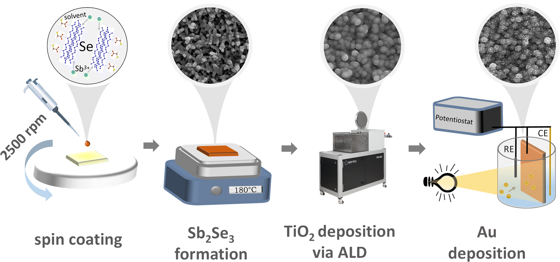 | ||
| Fig. 1 Schematic representation of the photoelectrode preparation from the Sb2Se3 layer synthesis via spin coating, up to the Au catalyst grafting using photo-electrodeposition, with the corresponding SEM images of the thin films. The illustration for the ink was adopted from ref. 25. | ||
Characterization of FTO/Au/Sb2Se3/TiO2 assemblies
Materials characterization was performed at the different stages of the preparation of the FTO/Au/Sb2Se3/TiO2 assemblies. To confirm the formation of Sb2Se3 from the precursor ink, we performed XRD measurements (Fig. 2A). Reflections from the used FTO/Au substrate were visible together with reflections related to the thin Sb2Se3 (JCPDS #15-0861) films. To deconvolute the contribution of the used FTO/Au substrates, we prepared Sb2Se3 thin films on glass substrates (Fig. 2A). In this case, better-resolved reflections were observed confirming the formation of Sb2Se3 with this preparation method. To reveal the phase purity of the formed Sb2Se3 films, Raman-spectroscopic measurements were carried out (Fig. 2B). The comparison of the observed vibrations with literature values is shown in Table S1 (ESI†). This comparison reveals the presence of Sb2Se3 without the formation of impurity phases, such as Sb2O3 or different forms of Se which could be observed at 250 cm−1 if present.9 After the deposition of the ALD TiO2 coating, no change in the Raman spectra of the samples was observed. This signals that no impurity phases were formed after the mild deposition. Furthermore, no vibrational modes related to TiO2 were observed on the recorded spectra revealing that under these deposition conditions (140 °C), an amorphous TiO2 coating is formed.51–53 Amorphous TiO2 layers formed under mild conditions are considered beneficial for PEC applications, as they offer proper electron conductivity to drive reduction reactions.54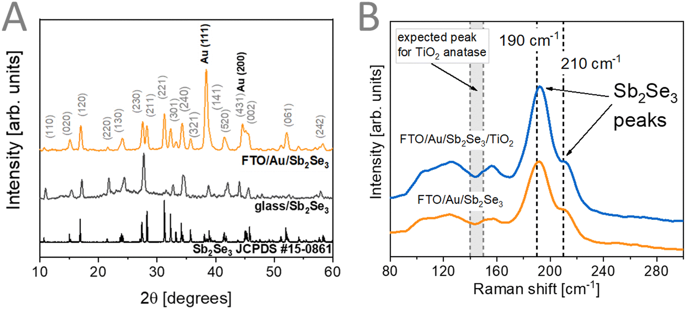 | ||
| Fig. 2 (A) XRD patterns of Sb2Se3 thin films prepared on glass and FTO/Au. (B) Raman spectra of FTO/Au/Sb2Se3 films before and after TiO2 deposition. | ||
XPS measurements were carried out (Fig. 3) to assess the surface chemical composition of the prepared samples. The binding energies for the different chemical elements and their assignment is shown in the ESI† (Table S2). The survey spectra (Fig. 3A) together with the core-level spectra of Sb 3d (Fig. 3B) reveal the formation of Sb2Se3 (Sb 3d5/2 at 529.17 eV, 57 at%) together with the presence of a surface Sb2O3 layer (Sb 3d5/2 at 538.51 eV, 43 at%). As Raman spectroscopy probes the bulk of the sample, this surface oxide layer is confined to the upmost part of the Sb2Se3 films. After ALD deposition of TiO2, the Sb and Se related peaks disappear completely, indicating that the TiO2 had conformal coverage over the Sb2Se3 film. The Ti 2p (Fig. 3C) and the O 1s (Fig. 3B) core-level spectra indicate the formation of TiO2 without the presence of reduced forms of Ti.
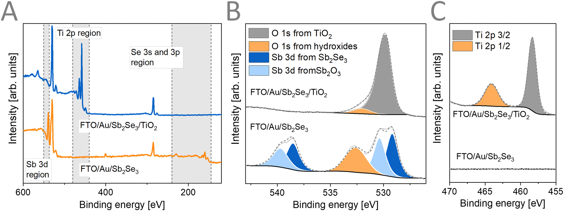 | ||
| Fig. 3 (A) XPS survey spectra, (B) Sb 3d with O 1s, and (C) Ti 2p high resolution core-level XPS spectra of FTO/Au/Sb2Se3 films before and after TiO2 deposition. | ||
Top-down SEM images were recorded (Fig. S2A and B, ESI†) at the different stages of the synthetic protocol to verify the conformality of the ALD TiO2 coating. During the multi-step spin coating procedure, Sb2Se3 nanorods were formed with an average diameter of 130 ± 25 nm. The thickness of the Sb2Se3 films was determined by cross-section SEM-FIB measurements (Fig. S2D–F, ESI†). An average thickness of 302 ± 90 nm was obtained. After the deposition of the ALD TiO2 layer, the nanorod structure was preserved, however with more rounded edges (Fig. S2B, ESI†). These samples showed a slightly larger thickness of 361 ± 77 nm caused by the deposited TiO2 layer. The light absorption properties of the Sb2Se3 films were characterized by UV-vis-NIR spectroscopy (Fig. S3A, ESI†). To extract the bandgap energy of the prepared Sb2Se3 films, Tauc analysis (Fig. S3B, ESI†), considering an indirect bandgap (supported by DFT calculations), was performed.55 A bandgap energy of 1.22 eV was determined which is in good agreement with literature values.48,55
To assess the PEC performance of the FTO/Au/Sb2Se3/TiO2 assemblies, we have benchmarked our photoelectrodes in PEC hydrogen evolution reaction (HER). We photo-deposited Pt as a cocatalyst on top of the ALD TiO2 layer (Fig. S4A, ESI†). The maximum photocurrent that our system could deliver was 19 mA cm−2 at −0.35 V vs. RHE (Fig. S4B, ESI†) which is in good agreement with the highest reported examples in the literature.5,25 This benchmarking was performed to remove the effect of variations from the FTO/Au/Sb2Se3/TiO2 architecture, and therefore allow meaningful comparison of the CO2RR data for the different photoelectrode assemblies.
Deposition of the Au catalyst
Fig. 4A illustrates the desired sample morphology we sought to obtain. The individual Sb2Se3 nanorods are conformally coated with the TiO2 layers. The conformality of the TiO2 layers is critically important to avoid the exposure of the bottom contact (i.e., FTO/Au) to the electrolyte. PEC methods can be used as a next step to decorate this architecture with the Au cocatalyst.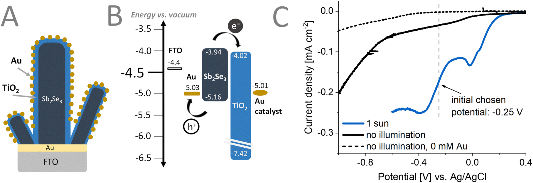 | ||
| Fig. 4 (A) Schematic representation of the photoelectrode assembly with the corresponding (B) band diagram. (C) Linear sweep voltammogram of the photoelectrode with and without 1 sun illumination with UV filter (AM1.5G, 100 mW cm−2, λ > 400 nm) in a solution of 0.5 mM KAuCl4 and 0.25 mM H2SO4 with 5% v/v methanol. | ||
Linear sweep voltammograms (LSVs) (Fig. 4C) were recorded under different conditions to optimize the deposition procedure of the Au cocatalyst on the Sb2Se3/TiO2 structure. As observed in the dashed gray LSV curve recorded in the absence of the Au salt, at an applied potential more negative than −0.3 V vs. Ag/AgCl, a reduction process occurs. When performing the Au deposition (Fig. 4C) under 1 sun illumination (blue line), an earlier onset potential of the deposition of Au can be observed, compared to the electrodeposition without illumination (black line). This is particularly helpful in avoiding other redox phenomena such as corrosion that might happen at more negative applied potentials. Furthermore, the applied potential suppresses recombination by extracting one of the charge carriers (in our case, holes) generated by the illumination. The long-lived carriers can better reach the surface of Sb2Se3 and participate in the chemical reaction (i.e., reduction of Au3+). By applying different deposition potentials under illumination, the properties (e.g., size, morphology, distribution) of the Au catalyst particles can be fine-tuned.
To understand the electronic coupling between the materials in the photoelectrode assembly, we performed UPS and contact potential difference measurements (Fig. S5–S7 and Table S3, ESI†), determining their Fermi-level and the valence band position. Together with the determined bandgap energies, the band diagram can be constructed (Fig. 4B). There was good agreement in the determined Fermi-level, band positions of the constituents except for the deposited Au catalyst. This can be ascribed to the inhomogeneity of the Au catalyst layer, that influences the work-function determination by UPS.56 After light excitation, the generated electrons in the Sb2Se3 can be efficiently extracted by the ALD deposited TiO2 layer. A conduction band offset of only 0.08 eV indicates an intimate contact (good interface quality) between these materials. In a similar manner, the used FTO/Au substrate, apart from orienting the growth of the Sb2Se3 nanorods, is capable of efficiently extracting the generated holes. The deep lying valence band of ALD TiO2 can also act as a hole-blocking layer, further suppressing electron–hole recombination at the surface of the samples.
Top-down SEM images (Fig. 5) show that the applied potential and passed charge both have an impact on the morphology and density of the deposited Au catalyst. We performed these depositions at three different potentials (−0.4 V, −0.25 V, and 0.1 V vs. Ag/AgCl) for three different total charge densities (25, 50, and 75 mC cm−2). These values correspond to 17, 34, and 51 ng cm−2 of Au loading respectively. When −0.4 V vs. Ag/AgCl (Fig. 5A and D) or −0.25 V vs. Ag/AgCl (Fig. 5B and E) was used with the same passed charge, small sized, finely dispersed Au catalysts were deposited on the sample surface. Notably, the average diameter of the Au nanoparticles at the same passed charge of 25 mC cm−2 were 26 ± 5 nm and 29 ± 6 nm for deposition potentials of −0.4 V vs. Ag/AgCl and −0.25 V vs. Ag/AgCl, respectively. For depositions performed at 0.1 V vs. Ag/AgCl, the Au catalysts are larger and more sparsely spaced (Fig. 5C and F) with an average diameter of 72 ± 17 nm at 25 mC cm−2 of passed charge (see size distribution in Fig. S8, ESI†). This signals that the nucleation of the Au catalyst is enhanced at deposition potentials that are more negative, leading to Au particles that are small and finely distributed throughout the Sb2Se3/TiO2 surface. By increasing the passed charge during deposition, the Au particles increased in size, ultimately leading to aggregation as observed in the 75 mC cm−2 case (Fig. 5D–F). Interestingly, when compared to the benchmark photoelectrodes with photo-deposited Pt having an average particle diameter of 12 ± 2 nm (Fig. S4, ESI†), the photo-electrodeposited Au particles are larger.
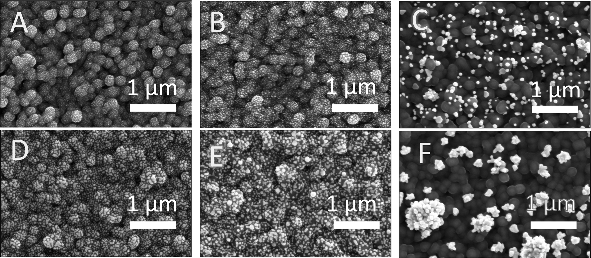 | ||
| Fig. 5 SEM images of FTO/Au/Sb2Se3/TiO2 with Au cocatalyst deposited at different biases −0.4 V (left: A and D), −0.25 V (middle: B and E), and 0.1 V (right: C and F) [referenced vs. Ag/AgCl] and at varying amounts of charge passed in mC cm−2: 25 (top: A–C), 75 (bottom: D–F). The scale bar corresponds to 1 μm. | ||
Photoelectrochemical CO2RR
To assess the PEC performance of the prepared Sb2Se3/TiO2/Au assemblies in CO2RR, we recorded linear sweep photovoltammograms under chopped illumination with 1 sun (Fig. 6A), in CO2-saturated 0.5 M KHCO3 electrolyte. Photoelectrodes where the Au deposition was carried out at −0.25 V vs. Ag/AgCl for a total charge passed of 75 mC cm−2 delivered a maximum photocurrent of ∼7.5 mA cm−2 at −0.57 V vs. RHE. This performance successfully competes with other single junction photoelectrodes using Au as the catalyst (Table S4, ESI†). We performed IPCE measurements (Fig. S9, ESI†) and observed that the rise of the photocurrent corresponds to the optical bandgap of Sb2Se3 which shows that there are negligible electronic losses in the assembly. In contrast, when performing dark CO2RR on a Au foil under similar conditions, the magnitude of the current was only ∼2 mA cm−2 at −0.57 V vs. RHE. Using a lower loading amount of 10 mC cm−2 leads to a decrease in the photocurrent (Fig. S10A and Fig. 6C, ESI†). Surprisingly, we found that after carrying out the deposition of Au catalyst above 25 mC cm−2, no further increase in the measured photocurrent (Fig. S11, ESI†) could be observed. This points toward other limiting factors (e.g., interface between the TiO2/Au) in these assemblies. Fig. 6B illustrates that without having all components in the photoelectrode, no PEC activity in CO2RR could be observed. Adding the Au catalyst on top of the bare Sb2Se3 without TiO2 leads to a poor rectifying behavior, which primarily acts like the standard Au foil under dark (orange line Fig. 6B similar to the star line in Fig. 6A; long-term performance Fig. S12, ESI†). This is because the photogenerated carriers are not extracted efficiently without any charge-selective contact (hole-extraction or electron extraction layer) allowing charge recombination to prevail. On the other hand, with solely a TiO2 protection layer, the rectifying behavior can be observed (blue line Fig. 6B). As no catalyst is deposited on the surface, and TiO2 itself drives PEC CO2RR poorly, no photocurrent could be observed. Achieving a satisfactory PEC performance can only be observed when the Au cocatalyst is deposited on the TiO2 surface.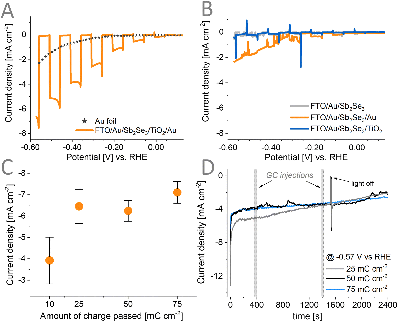 | ||
| Fig. 6 Linear sweep photovoltammogram under 1 sun illumination (AM1.5G, 100 mW cm−2) of (A) the complete architecture (Au catalyst loading of 75 mC cm−2 deposited at −0.25 V vs. Ag/AgCl) and (B) the set of incomplete electrode architectures in a CO2-saturated solution of 0.5 M KHCO3. (C) Recorded current density at −0.57 V vs. RHE for different catalyst loadings deposited at −0.25 V vs. Ag/AgCl. (D) Long-term chronoamperometry measurement of the architecture with different catalyst loadings deposited at −0.25 V vs. Ag/AgCl. | ||
To evaluate the stability of the assemblies, photoelectrolysis was carried out for 30 minutes at an applied potential of −0.57 V vs. RHE with three different loadings of the Au catalyst (Fig. 6D). The lowest loading of 25 mC cm−2 showed relatively higher photocurrent at the first 1200 s and then reached the same performance as the other two loadings. The initial decay of the photocurrent is apparent, and this is attributed to the inherent behavior of Au under similar CO2RR conditions (Fig. S13, ESI†). The used Au foil also displays a similar decay trend as the prepared photoelectrodes. This decay can be divided into two regions: (1) a quick initial drop for the first 10 s and (2) a constant slow decay. We have performed XPS and Raman spectroscopy to characterize the chemical composition of the photoelectrodes in these two regions. Both techniques suggest that the chemical composition of the electrodes remain unchanged within the 1st region (Fig. S14A and S15A–C, ESI†). Therefore, this quick drop at the start might be due to the double layer charging effect resulting from the sudden step from OCP to an applied −1.2 V vs. Ag/AgCl potential during these measurements. For the second region multiple effects can contribute to the observed behavior such as: (i) the change in alkalinity of the electrolyte as the CO2RR/HER proceeds,57 (ii) photocorrosion of the TiO2 layer, (iii) the corrosion of the Sb2Se3 once TiO2 fully delaminates, and (iv) partial removal of the Au catalysts. Fig. S10B (ESI†) also shows that redeposition of the Au catalyst does not retrieve the initial photocurrent. This points to the fact that part of the CO2RR activity fading is permanent and not only caused by the catalyst removal, and the photocorrosion of the TiO2 layer is also at play (shown by Raman and XPS results in Fig. S14 and S15, ESI†).
Product distribution during PEC CO2RR
The main product when performing CO2RR on Au surfaces is CO.58 Aside from CO, hydrogen is also reported in many studies as a by-product. We performed an Ar-bubbled photoelectrolysis experiment at −0.57 V vs. RHE and we found that no CO product was formed but only hydrogen (Fig. S16, ESI†). To verify the source of the CO in our PEC experiments (where CO2 was bubbled), we have performed CO2RR with labelled 13CO2 and KH13CO3 (Fig. S17, ESI†). These experiments proved that the observed CO is not from any additional source used in the photoelectrode or the setup itself. We also carried out liquid product detection experiments using ion chromatography and NMR spectroscopy which showed that no liquid products were formed during the photoelectrolysis. We explored the effects of varying both (1) the deposition potential of the Au catalyst and (2) the amount of Au catalyst on the performance of the photoelectrodes for CO2RR. Although the particle size and morphology of the Au catalyst differ as previously seen in the SEM images (Fig. 5), we found that this has no correlation to the products detected and that there is no clear trend to be observed (Fig. 7). For the amount of 50 mC cm−2 of charge passed, the average FECO is around 24% independent of the applied potential during the deposition of Au. The size range of the Au nanoparticles (26 ± 5 nm, 29 ± 6 nm, up to 72 ± 17 nm) is too large to have a significant contribution to the performance as reported in the literature for similar Au nanoparticle-based photoelectrodes.31,59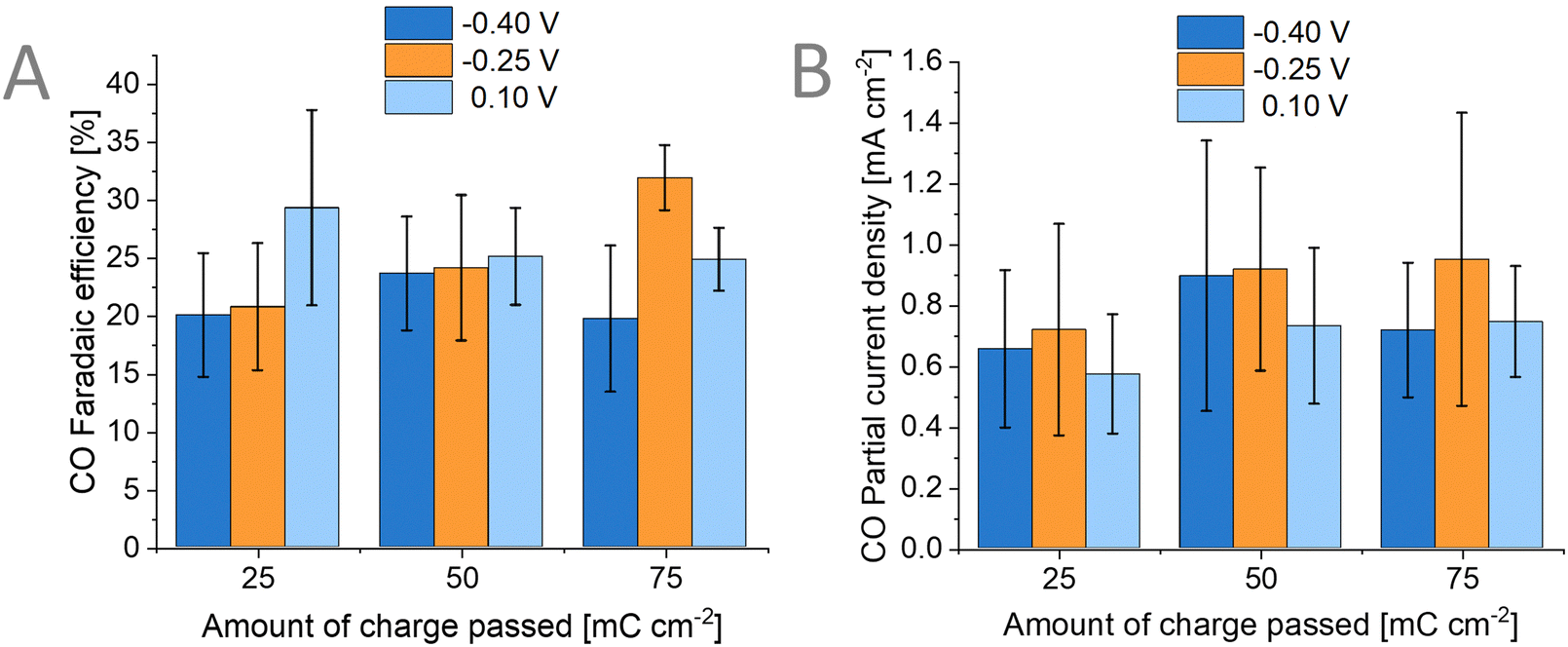 | ||
| Fig. 7 (A) Faradaic efficiency for CO of the FTO/Au/Sb2Se3/TiO2/Au photoelectrode with corresponding (B) partial current density for CO at different deposition bias (−0.4 V, −0.25 V, 0.1 V vs. Ag/AgCl) and different amount of charge passed (25, 50, 75 mC cm−2) for the Au catalyst deposition. | ||
Conclusions
In summary, we have studied Sb2Se3-based photoelectrodes for CO2 reduction by harnessing the photogenerated charge carriers of the semiconductor and the catalytic activity of photo-electrodeposited Au cocatalysts. Using a materials-focused approach of photocathode fabrication, we have developed (i) a nano-structured semiconductor that has good light absorption, (ii) a conformal amorphous TiO2 coating that acted as both protection layer and electron extraction layer, and (iii) a highly dispersed Au nanoparticle cocatalyst. This assembly was explored in PEC CO2RR, where the photoelectrode architecture delivered an average photocurrent density of ∼7.5 mA cm−2 at −0.57 V vs. RHE, which is a threefold increase from the performance of a Au foil in the same CO2RR conditions (2 mA cm−2). This improved performance compared to a Au foil validates the research directions towards employing direct PEC CO2RR. The FECO was not affected significantly by the deposition bias nor the amount of Au catalyst. The average FECO is 25 ± 6% while FEH2 is 63 ± 12%, indicating roughly a ∼1:2.5 CO/H2 ratio. Overall, we have shown that Sb2Se3-based photoelectrode assemblies can also be used for PEC CO2RR by employing Au cocatalyst. This study highlights the importance of utilizing already existing architectures and repurposing/re-engineering them for the specific applications intended.
Author contributions
John Mark Christian M. Dela Cruz: methodology, investigation, validation, data curation, writing – original draft, visualization, project administration. Ádám Balog: investigation, data curation. Péter S. Tóth: investigation, data curation. Gábor Bencsik: investigation. Gergely F. Samu: conceptualization, investigation, data curation, writing – review & editing, supervision. Csaba Janáky: conceptualization, resources, writing – review & editing, supervision, funding acquisition.Conflicts of interest
There are no conflicts to declare.Acknowledgements
We would like to thank Dr Veronika Hanyecz for her help in the Au underlayer deposition procedure and Dr Attila Csík for performing the GIXRD measurements. This project has received funding under the European Union's Horizon Europe research and innovation program from the European Research Council (ERC, grant agreement no. 101043617) and under the H2020 Marie Skłodowska-Curie grant agreement no. 861151 Solar2Chem. The Authors also thank the Hungarian support through the project no. RRF-2.3.1-21-2022-00009, titled National Laboratory for Renewable Energy. This has been implemented with the support provided by the Recovery and Resilience Facility of the European Union within the framework of Programme Széchenyi Plan Plus. The ELI ALPS project (GINOP-2.3.6-15-2015-00001) is supported by the European Union and co-financed by the European Regional Development Fund.Notes and references
- G. Segev, J. Kibsgaard, C. Hahn, Z. J. Xu, W.-H. (Sophia) Cheng, T. G. Deutsch, C. Xiang, J. Z. Zhang, L. Hammarström, D. G. Nocera, A. Z. Weber, P. Agbo, T. Hisatomi, F. E. Osterloh, K. Domen, F. F. Abdi, S. Haussener, D. J. Miller, S. Ardo, P. C. McIntyre, T. Hannappel, S. Hu, H. Atwater, J. M. Gregoire, M. Z. Ertem, I. D. Sharp, K.-S. Choi, J. S. Lee, O. Ishitani, J. W. Ager, R. R. Prabhakar, A. T. Bell, S. W. Boettcher, K. Vincent, K. Takanabe, V. Artero, R. Napier, B. R. Cuenya, M. T. M. Koper, R. V. D. Krol and F. Houle, J. Phys. Appl. Phys., 2022, 55, 323003 CrossRef.
- R. van de Krol and B. A. Parkinson, MRS Energy Sustain., 2017, 4, 13 CrossRef.
- Advanced Alternative Fuels – Technology Development Report 2020.
- S. Ardo, D. F. Rivas, M. A. Modestino, V. S. Greiving, F. F. Abdi, E. A. Llado, V. Artero, K. Ayers, C. Battaglia, J.-P. Becker, D. Bederak, A. Berger, F. Buda, E. Chinello, B. Dam, V. D. Palma, T. Edvinsson, K. Fujii, H. Gardeniers, H. Geerlings, S. M. H. Hashemi, S. Haussener, F. Houle, J. Huskens, B. D. James, K. Konrad, A. Kudo, P. P. Kunturu, D. Lohse, B. Mei, E. L. Miller, G. F. Moore, J. Muller, K. L. Orchard, T. E. Rosser, F. H. Saadi, J.-W. Schüttauf, B. Seger, S. W. Sheehan, W. A. Smith, J. Spurgeon, M. H. Tang, R. van de Krol, P. C. K. Vesborg and P. Westerik, Energy Environ. Sci., 2018, 11, 2768–2783 RSC.
- J. Kim, W. Yang, Y. Oh, H. Lee, S. Lee, H. Shin, J. Kim and J. Moon, J. Mater. Chem. A, 2017, 5, 2180–2187 RSC.
- S. Chen, T. Liu, Z. Zheng, M. Ishaq, G. Liang, P. Fan, T. Chen and J. Tang, J. Energy Chem., 2022, 67, 508–523 CrossRef CAS.
- H. Lee, W. Yang, J. Tan, Y. Oh, J. Park and J. Moon, ACS Energy Lett., 2019, 4, 995–1003 CrossRef CAS.
- J. Park, W. Yang, J. Tan, H. Lee, J. W. Yun, S. G. Shim, Y. S. Park and J. Moon, ACS Energy Lett., 2020, 5, 136–145 CrossRef CAS.
- J. Tan, W. Yang, Y. Oh, H. Lee, J. Park, R. Boppella, J. Kim and J. Moon, Adv. Energy Mater., 2019, 9, 1900179 CrossRef.
- X. Liu, J. Chen, M. Luo, M. Leng, Z. Xia, Y. Zhou, S. Qin, D.-J. Xue, L. Lv, H. Huang, D. Niu and J. Tang, ACS Appl. Mater. Interfaces, 2014, 6, 10687–10695 CrossRef CAS PubMed.
- W. Yang, X. Zhang and S. D. Tilley, Chem. Mater., 2021, 33, 3467–3489 CrossRef CAS.
- Y. Zhou, L. Wang, S. Chen, S. Qin, X. Liu, J. Chen, D.-J. Xue, M. Luo, Y. Cao, Y. Cheng, E. H. Sargent and J. Tang, Nat. Photonics, 2015, 9, 409–415 CrossRef CAS.
- J. Park, W. Yang, Y. Oh, J. Tan, H. Lee, R. Boppella and J. Moon, ACS Energy Lett., 2019, 4, 517–526 CrossRef CAS.
- X. Wen, C. Chen, S. Lu, K. Li, R. Kondrotas, Y. Zhao, W. Chen, L. Gao, C. Wang, J. Zhang, G. Niu and J. Tang, Nat. Commun., 2018, 9, 2179 CrossRef PubMed.
- O. S. Hutter, L. J. Phillips, K. Durose and J. D. Major, Sol. Energy Mater. Sol. Cells, 2018, 188, 177–181 CrossRef CAS.
- C. Chen, K. Li, S. Chen, L. Wang, S. Lu, Y. Liu, D. Li, H. Song and J. Tang, ACS Energy Lett., 2018, 3, 2335–2341 CrossRef CAS.
- G.-X. Liang, Z.-H. Zheng, P. Fan, J.-T. Luo, J.-G. Hu, X.-H. Zhang, H.-L. Ma, B. Fan, Z.-K. Luo and D.-P. Zhang, Sol. Energy Mater. Sol. Cells, 2018, 174, 263–270 CrossRef CAS.
- T. T. Ngo, S. Chavhan, I. Kosta, O. Miguel, H.-J. Grande and R. Tena-Zaera, ACS Appl. Mater. Interfaces, 2014, 6, 2836–2841 CrossRef CAS PubMed.
- M. B. Costa, F. W. S. Lucas and L. H. Mascaro, J. Mater. Chem. A, 2020, 8, 13742–13753 RSC.
- R. R. Prabhakar, W. Septina, S. Siol, T. Moehl and S. D. Tilley, J. Mater. Chem. A, 2017, 5, 23139–23145 RSC.
- L. Gao, Y. Cui, R. H. J. Vervuurt, D. van Dam, R. P. J. van Veldhoven, J. P. Hofmann, A. A. Bol, J. E. M. Haverkort, P. H. L. Notten, E. P. A. M. Bakkers and E. J. M. Hensen, Adv. Funct. Mater., 2016, 26, 679–686 CrossRef CAS.
- N. Guijarro, M. S. Prévot and K. Sivula, Phys. Chem. Chem. Phys., 2015, 17, 15655–15674 RSC.
- M. Crespo-Quesada and E. Reisner, Energy Environ. Sci., 2017, 10, 1116–1127 RSC.
- P. Acevedo-Peña, J. Vazquez-Arenas, R. Cabrera-Sierra, L. Lartundo-Rojas and I. González, J. Electrochem. Soc., 2013, 160, C277 CrossRef.
- W. Yang, J. Ahn, Y. Oh, J. Tan, H. Lee, J. Park, H.-C. Kwon, J. Kim, W. Jo, J. Kim and J. Moon, Adv. Energy Mater., 2018, 8, 1702888 CrossRef.
- J. Tan, B. Kang, K. Kim, D. Kang, H. Lee, S. Ma, G. Jang, H. Lee and J. Moon, Nat. Energy, 2022, 1–11 Search PubMed.
- X. Li, J. Yu, M. Jaroniec and X. Chen, Chem. Rev., 2019, 119, 3962–4179 CrossRef CAS PubMed.
- V. Kumaravel, J. Bartlett and S. C. Pillai, ACS Energy Lett., 2020, 5, 486–519 CrossRef CAS.
- J. L. White, M. F. Baruch, J. E. Pander, Y. Hu, I. C. Fortmeyer, J. E. Park, T. Zhang, K. Liao, J. Gu, Y. Yan, T. W. Shaw, E. Abelev and A. B. Bocarsly, Chem. Rev., 2015, 115, 12888–12935 CrossRef CAS PubMed.
- G. Liu, P. R. Narangari, Q. T. Trinh, W. Tu, M. Kraft, H. H. Tan, C. Jagadish, T. S. Choksi, J. W. Ager, S. Karuturi and R. Xu, ACS Catal., 2021, 11, 11416–11428 CrossRef CAS.
- S. Chu, P. Ou, R. T. Rashid, Y. Pan, D. Liang, H. Zhang and J. Song, Green Energy Environ., 2022, 7, 545–553 CrossRef CAS.
- Y. J. Jang, J.-W. Jang, J. Lee, J. H. Kim, H. Kumagai, J. Lee, T. Minegishi, J. Kubota, K. Domen and J. S. Lee, Energy Environ. Sci., 2015, 8, 3597–3604 RSC.
- K. Wang, N. Fan, B. Xu, Z. Wei, C. Chen, H. Xie, W. Ye, Y. Peng, M. Shen and R. Fan, Small, 2022, 18, 2201882 CrossRef CAS PubMed.
- J. T. Song, H. Ryoo, M. Cho, J. Kim, J.-G. Kim, S.-Y. Chung and J. Oh, Adv. Energy Mater., 2017, 7, 1601103 CrossRef.
- Y. J. Jang, I. Jeong, J. Lee, J. Lee, M. J. Ko and J. S. Lee, ACS Nano, 2016, 10, 6980–6987 CrossRef CAS PubMed.
- J. S. DuChene, G. Tagliabue, A. J. Welch, W.-H. Cheng and H. A. Atwater, Nano Lett., 2018, 18, 2545–2550 CrossRef CAS PubMed.
- I. Roh, S. Yu, C.-K. Lin, S. Louisia, S. Cestellos-Blanco and P. Yang, J. Am. Chem. Soc., 2022, 144, 8002–8006 CrossRef CAS PubMed.
- B. Zhou, P. Ou, N. Pant, S. Cheng, S. Vanka, S. Chu, R. T. Rashid, G. Botton, J. Song and Z. Mi, Proc. Natl. Acad. Sci. U. S. A., 2020, 117, 1330–1338 CrossRef CAS PubMed.
- H. A. Chaliyawala, S. Bastide, D. Muller-Bouvet, C. Pichon, K. Bah, A. Djoumoi, F. Marty, T. Bourouina and E. Torralba, ACS Appl. Energy Mater., 2023, 6, 8397–8409 CrossRef CAS.
- Y. Hu, F. Chen, P. Ding, H. Yang, J. Chen, C. Zha and Y. Li, J. Mater. Chem. A, 2018, 6, 21906–21912 RSC.
- C. Kim, S. Choi, M.-J. Choi, S. A. Lee, S. H. Ahn, S. Y. Kim and H. W. Jang, Appl. Sci., 2020, 10, 3487 CrossRef CAS.
- P. B. Pati, R. Wang, E. Boutin, S. Diring, S. Jobic, N. Barreau, F. Odobel and M. Robert, Nat. Commun., 2020, 11, 3499 CrossRef CAS PubMed.
- A. Call, M. Cibian, K. Yamamoto, T. Nakazono, K. Yamauchi and K. Sakai, ACS Catal., 2019, 9, 4867–4874 CrossRef CAS.
- V. Andrei, B. Reuillard and E. Reisner, Nat. Mater., 2020, 19, 189–194 CrossRef CAS PubMed.
- Q. Wang, J. Warnan, S. Rodríguez-Jiménez, J. J. Leung, S. Kalathil, V. Andrei, K. Domen and E. Reisner, Nat. Energy, 2020, 5, 703–710 CrossRef CAS.
- H. A. Hansen, J. B. Varley, A. A. Peterson and J. K. Nørskov, J. Phys. Chem. Lett., 2013, 4, 388–392 CrossRef CAS PubMed.
- S. Chu, P. Ou, P. Ghamari, S. Vanka, B. Zhou, I. Shih, J. Song and Z. Mi, J. Am. Chem. Soc., 2018, 140, 7869–7877 CrossRef CAS PubMed.
- W. Yang and J. Moon, J. Mater. Chem. A, 2019, 7, 20467–20477 RSC.
- C. Tossi, L. Hällström, J. Selin, M. Vaelma, E. See, J. Lahtinen and I. Tittonen, J. Mater. Chem. A, 2019, 7, 14519–14525 RSC.
- N. Fairley, V. Fernandez, M. Richard-Plouet, C. Guillot-Deudon, J. Walton, E. Smith, D. Flahaut, M. Greiner, M. Biesinger, S. Tougaard, D. Morgan and J. Baltrusaitis, Appl. Surf. Sci. Adv., 2021, 5, 100112 CrossRef.
- T. Moehl, J. Suh, L. Sévery, R. Wick-Joliat and S. D. Tilley, ACS Appl. Mater. Interfaces, 2017, 9, 43614–43622 CrossRef CAS PubMed.
- A. Jolivet, C. Labbé, C. Frilay, O. Debieu, P. Marie, B. Horcholle, F. Lemarié, X. Portier, C. Grygiel, S. Duprey, W. Jadwisienczak, D. Ingram, M. Upadhyay, A. David, A. Fouchet, U. Lüders and J. Cardin, Appl. Surf. Sci., 2023, 608, 155214 CrossRef CAS.
- A. Niilisk, M. Moppel, M. Pärs, I. Sildos, T. Jantson, T. Avarmaa, R. Jaaniso and J. Aarik, Open Phys., 2006, 4, 105–116 CAS.
- S. Hu, M. R. Shaner, J. A. Beardslee, M. Lichterman, B. S. Brunschwig and N. S. Lewis, Science, 2014, 344, 1005–1009 CrossRef CAS PubMed.
- R. Vadapoo, S. Krishnan, H. Yilmaz and C. Marin, Phys. Status Solidi B, 2011, 248, 700–705 CrossRef CAS.
- J. W. Kim and A. Kim, Curr. Appl. Phys., 2021, 31, 52–59 CrossRef.
- A. Goyal, G. Marcandalli, V. A. Mints and M. T. M. Koper, J. Am. Chem. Soc., 2020, 142, 4154–4161 CrossRef CAS PubMed.
- Y. Hori, in Modern Aspects of Electrochemistry, ed. C. G. Vayenas, R. E. White and M. E. Gamboa-Aldeco, Springer New York, New York, NY, 2008, vol. 42, pp. 89–189 Search PubMed.
- C. Li, T. Wang, B. Liu, M. Chen, A. Li, G. Zhang, M. Du, H. Wang, S. F. Liu and J. Gong, Energy Environ. Sci., 2019, 12, 923–928 RSC.
Footnote |
| † Electronic supplementary information (ESI) available. See DOI: https://doi.org/10.1039/d3ey00222e |
| This journal is © The Royal Society of Chemistry 2024 |