
 Open Access Article
 This Open Access Article is licensed under a Creative Commons Attribution-Non Commercial 3.0 Unported Licence
On the role of membrane embedding, protein rigidity and transmembrane length in lipid membrane fusion
Marco
van Tilburg†
 a,
Peter A. J.
Hilbers
ab and
Albert J.
Markvoort
*ab
a,
Peter A. J.
Hilbers
ab and
Albert J.
Markvoort
*ab
aDepartment of Biomedical Engineering, Computational Biology Group, Eindhoven University of Technology, The Netherlands. E-mail: A.J.Markvoort@tue.nl
bInstitute of Complex Molecular Systems, Eindhoven University of Technology, The Netherlands
First published on 8th February 2023
Abstract
The fusion of biological membranes is ubiquitous in natural processes like exo- and endocytosis, intracellular trafficking and viral entry. Membrane fusion is also utilized in artificial biomimetic fusion systems, e.g. for drug delivery. Both the natural and the biomimetic fusion systems rely on a wide range of (artificial) proteins mediating the fusion process. Although the exact mechanisms of these proteins differ, clear analogies in their general behavior can be observed in bringing the membranes in close proximity and mediating the fusion reaction. In our study, we use molecular dynamics simulations with coarse grained models, mimicking the general behavior of fusion proteins (spikes), to systematically examine the effects of specific characteristics of these proteins on the fusion process. The protein characteristics considered are (i) the type of membrane embedding, i.e., either transmembrane or not, (ii) the rigidity, and (iii) the transmembrane domain (TMD) length. The results show essential differences in fusion pathway between monotopic and transmembrane spikes, in which transmembrane spikes seem to inhibit the formation of hemifusion diaphragms, leading to a faster fusion development. Furthermore, we observed that an increased rigidity and a decreased TMD length both proved to contribute to a faster fusion development. Finally, we show that a single spike may suffice to successfully induce a fusion reaction, provided that the spike is sufficiently rigid and attractive. Not only does this shed light on biological fusion of membranes, it also provides clear design rules for artificial membrane fusion systems.
Introduction
Fusion of biological membranes is one of the most fundamental processes in eukaryotic organisms and occurs when two separate lipid membranes merge into a single continuous lipid bilayer.1–4 Such membrane fusion plays an important role in vesicle trafficking and secretion, in which transport vesicles release their material by fusing with a target membrane.5 Moreover, enveloped viruses6–8 such as HIV-1,9 Influenza10 and all types of coronaviruses11 rely on this process in order to infect host cells as well. Fusion of two lipid membranes however rarely occurs spontaneously due to hydration repulsion between the membranes; a thin layer of water molecules acting as a barrier to prevent sticking of biological matter.12To overcome the hydration barrier, various protein types are involved in natural fusion processes. In the case of vesicle trafficking, fusion is mainly mediated by SNARE-proteins.13,14 These are thread shaped proteins residing on both membranes (Fig. 1a) that fit together and close like a zipper to pull both membranes in close proximity.15 Viral entry on the other hand is mainly regulated by a wide range of fusion peptides divided into different classes.16–18 Such viruses use proteins residing on the target membrane to insert their own fusion proteins into the target membrane, after which a conformational change pulls the membranes towards each other (Fig. 1b). Although the molecular structures and exact mechanism of action of these fusion proteins differ in many ways, the general principle is essentially comparable; a connection is made between the membranes of the vesicle or viral particle and the host cell, after which both membranes are brought in close proximity due to a series of actions and conformational changes of the fusion proteins. This process overcomes the hydration barrier and brings the membranes close enough to induce membrane fusion.
 | ||
| Fig. 1 Protein (mimetic) mediated membrane fusion and the simulation model. (a–c) Schematics of the functioning of (a) SNARE-proteins, (b) influenza hemagglutinin, and (c) synthetic fusion proteins. (d) CG-model of a phospholipid (G4T4T4). Hydrophobic beads are colored green, hydrophilic beads are colored gray. (e) The CG spike models. The ligand/receptor part, displayed in shades of blue, consists of bead types L1/R1 to L6/R6 appearing in pairs. The TMD is colored green and consists of hydrophobic T-beads. Anchored spikes have two hydrophilic G beads (gray) connected to the TMD. (f) A schematic representation of the difference in positioning in the membrane of anchored (transmembrane) and unanchored (monotopic) spikes. Anchored spikes possess two hydrophilic beads (gray), connecting the TMD to the trans-leaflet of the membrane. Unanchored spikes lack these beads, making their TMD able to move inside the membrane. (g) A schematic representation of the formation of a “zipper” conformation, pulling the two membranes together, via an attractive interaction between Li and Ri. (h) An initial configuration of the simulation box, consisting of a bilayer with 144 receptors (blue) and a vesicle with 30 ligands (red). Water beads filling the remaining volume are left out of the representation for clarity. Panel (a) has been adapted from Bassereau et al., J. Phys. D: Appl. Phys, 2018, 51, 343001.92 Panel (b) has been adapted from Pabis et al., PNAS, 2020, 117, 7200.68 Panel (c) has been adapted from Rabe et al., Biophys J, 2016, 111, 2162.61 | ||
Inspired by the natural fusion proteins, also a variety of simpler synthetic fusion protein mimics have been developed. These mimics, typically constituted of some membrane anchor and recognition unit attached to each other via a linker (Fig. 1c), allowed for a more systematic investigation of membrane fusion and the role of fusion proteins therein. Examples of such synthetic fusogens have been reported based on small molecule recognition,19–22 complementary DNA23–25 and PNA,26,27 as well as coiled-coil peptides,28–31 where the tethering to the membrane varied from a single sterol, fatty acid, or phospholipid to quadruple lipid anchors and native SNARE transmembrane domains. For the coiled-coil peptide system of Kros,29 for example, apart from the nature32 and position33 of the lipid anchor, also the effect on the fusion process has been investigated of variables such as the length of the linker,34 peptide orientation35 as well as the length36 and oligomer state37 of the peptides. Despite the fact that this coiled-coil peptide system has been demonstrated to be applicable in vitro as well as in vivo for targeted liposomal drug delivery,38 also in a clinically relevant setting,39 many of the artificial fusion systems remain rather inefficient, often halting in hemifused states.
To obtain an enhanced molecular level understanding of the fusion process, various molecular simulation models have been used, as e.g. reviewed in ref. 40 and 41. Initial studies focused on protein free membranes under highly fusogenic conditions, for instance exhibiting negative spontaneous curvature lipids, tension, high positive membrane curvature, or partial dehydration. Atomistic simulations allowed to look at fusion relevant events using small pieces of bilayer, such as lamellar to non-lamellar phase transitions,42 pore formation,43 and disorientation of lipid tails in closely apposed bilayers,44 as well as at the fusion of a small vesicle with itself via the periodic boundaries.45 However, to reduce the effect of the boundary conditions especially coarse grained models have been used to simulate the fusion of complete vesicles46–53 as well as its inverse process of fission.54–56 These simulations provided a detailed molecular picture of the role of lipids in the fusion process, showing fusion intermediates, alternative fusion pathways, and rate-limiting steps. For instance, they showed the importance of lipid splay as a first step and the importance of asymmetric hemifusion intermediates in the fusion process.
Molecular simulations have also been used for the exploration of the mechanisms of action of fusion proteins. These simulation studies vary again from atomistic level simulations of small pieces of bilayer surrounding (part of) a fusion protein, to coarse grained simulations of protein mediated fusion of an entire vesicle with a larger bilayer. Atomistic simulations for instance showed that the presence of influenza fusion peptides locally perturbs the lipid packing of the membranes which increases lipid tail protrusion leading to the formation of a hydrophobic bridge57 and that this lipid tail protrusion is reduced for less fusion-active mutants.58 Other simulations showed how transmembrane domains may contribute to the process of virus-cell membrane fusion in HIV-1 infection59 and investigated the mechanical properties of the linker for SNARE proteins.60 Also for the peptide-based synthetic fusion system of Kros atomistic simulations have been performed, showing how the peptides may interact with the membrane, accumulating DOPE lipids.61 The increased system size reachable with coarse grained simulations has been used to study larger bilayers containing multiple peptides, e.g. showing the role of fusion peptides in promoting positive membrane curvature,62 the role of peptide bundling,63 and the clustering of transmembrane proteins.64 While Wu and Guo65 used a simplified coarse grained model of fusion proteins to fuse two small vesicles, multiple studies focused on specific fusion proteins, like the fusion mediated by lung surfactant protein B,66 SNARE proteins67 or influenza hemagglutinin.68 Risselada et al.67 concluded that the fusion process is not exclusively lipidic as considered before, but that SNARE-complexes are actively involved in the fusion process in several ways. In the first place, expansion of the fusion stalk seems to be driven by stresses of assembled SNARE-complexes. Secondly, these complexes might prevent the formation of a hemifusion diaphragm. Finally, they initiate pore opening by exerting force on the trans-leaflets of the membranes. Sharma et al.69 used CG-models of SNARE-proteins as well, showing that the distance between assembled SNARE-complexes determines how fast the fusion develops and that specific mutations of the SNARE transmembrane regions can hinder pore formation, but not stalk formation, such that fusion halts in a hemifused state. Moreover, such simulations have also been used to quantify the underlying free energy landscape,70e.g. showing that the free energy landscape of stalk expansion is highly affected by subtle differences in membrane environment, such as leaflet composition, asymmetry, and flexibility.71
Aforementioned simulations of fusion proteins and protein mimics focused mainly on the precise mechanism of a particular fusion protein. Apart from the direct visualization of the fusion process and the investigation of its free energy landscape, another advantage of computer simulations over experimental methods is that variables in the system and molecular characteristics can be varied readily, allowing to systematically explore the importance and contribution of these characteristics on the system. Here, we use molecular dynamics (MD) simulations to examine the importance of various characteristics of fusion proteins (spikes) in general. Main goal is to study the role of the transmembrane domain, present in many fusion proteins, on the fusion process. Therefore, we compare simulations of spikes containing a transmembrane domain with simulations of monotopic spikes that lack a hydrophilic anchor in the trans-leaflet. Our hypothesis is that the fusion develops slower and according to a different pathway if this anchor is absent since the anchor may exert force on the trans-leaflets of the membranes. Furthermore, we examine the effects of the length of the TMD on the fusion process and how the rigidity of the spikes affects the different phases of the fusion pathway. We hypothesize that especially in case of transmembrane spikes, the rigidity and TMD-length play an important role in the transmission of force across the length of the spike. Our study distinguishes from previous work by the fusion protein models used. To allow for the systematic variation of aforementioned fusion protein characteristics, we use a non-specific and coarse-grained spike model that mimics the general behavior of fusion proteins (see Fig. 1d–h). To examine this process and to provide design rules for artificial membrane fusion systems, we simulate the fusion of a small vesicle containing ligand spikes, with a flat bilayer containing receptor spikes, where the ligands and receptors are initially unbound.
Methods
Model
Membranes have been built using a CG-model of phospholipid (DPPC) molecules72 and a variety of CG-spike models. The CG-lipid model has been used before to study for instance the spontaneous aggregation of lipids into bilayers and the bilayer-vesicle transition,72 the deformation of (osmotically) deflating vesicles,73,74 and membrane fission.54 One such CG-lipid comprises two tails of four hydrophobic T-beads and a head group consisting of four hydrophilic G-beads (see Fig. 1d). W-beads act as solvent, where a single W-bead represents four water molecules. All CG-spike models consist of a linear chain of beads with the same size and mass as the G- and T-beads (Fig. 1e). The mechanism of the spike models is based on the zipper mechanism of SNARE-proteins.75,76 For this, complementary spikes were constructed with an attractive interaction between spike beads of the same index, i.e., ligand-spikes that reside in the vesicle membrane and receptor-spikes that reside in the bilayer membrane. When the tips of both spikes make contact, the second beads of both spikes will be sufficiently close to attract each other. This process continues and closes the “zipper”, causing the vesicle to move in the direction of the bilayer. A schematic representation of this principle can be viewed in Fig. 1g.Fig. 1e shows the exact structure of three of these spike models. All spike models are 22 CG-beads long and start with a chain of hydrophilic ligand or receptor beads. The length of this chain is based on the length of SNARE-proteins of approximately 7 nm.77 This chain is followed by a hydrophobic transmembrane domain (TMD), either or not followed by a hydrophilic end. The ligand and receptor part are composed of six different bead types denoted as L1 (ligands)/R1 (receptors) to L6/R6, appearing in pairs of the same type starting from the tip of the spike to the TMD. The TMD is composed of hydrophobic T-beads and the possible hydrophilic end is composed of two G-beads. The spikes with the two hydrophilic G-beads at the end span both leaflets of the membrane and will be denoted as transmembrane spikes. The ends of the spikes without these G-beads reside in the hydrophobic core of the membrane and these unanchored spikes will be denoted as monotopic spikes. The difference is illustrated in Fig. 1f. The naming convention for the spikes is such that the first letter indicates whether it is a receptor (R) or a ligand (L). This is followed by the letters TMD and the number of hydrophobic beads the TMD consists of. Finally, an A is added if the spike has a hydrophilic anchor, i.e., is a transmembrane protein, or a U is added if such an anchor is absent, i.e., if it is a monotopic protein.
Simulation box
Simulations have been performed in a cubic simulation box of approximately 64![[thin space (1/6-em)]](https://www.rsc.org/images/entities/char_2009.gif) 000 nm3 (40 × 40 × 40 nm), consisting of three main components: a vesicle, representing a viral particle or transport vesicle, a flat square bilayer, representing a cell membrane, and spike models. Each of those components were created separately and finally merged into one simulation box, after which the remaining volume was filled with water beads. To create the bilayer, a 10 × 10 × 10 nm simulation box was randomly filled with 240 lipids and 645 water beads. Due to periodic boundary conditions and the interactions between different beads, eventually a single bilayer was formed parallel to the xy-plane as explained in ref. 72. This bilayer was repeated four times in both the x- and y-direction to yield a bilayer consisting of 3840 lipids (two monolayers of exactly 1920 lipids each). The vesicle was created, again following ref. 72, by surrounding a bilayer with water beads. A cylindrical patch consisting of 516 lipids was cut out of the above-described flat bilayer, which in 18 ns of simulation, bended and finally closed, enveloping part of the water, thus forming a vesicle. Although this vesicle, with a diameter of approximately 15 nm, is rather small, it thus formed spontaneously and does not fuse automatically with a bilayer. These elements were combined into different systems. To create a system with multiple spikes, first, 30 ligands and 144 receptors were added to the vesicle and the bilayer, respectively. To distribute the ligands equally across the vesicle surface, each ligand was positioned at the center of the edge of an icosahedron, which led to an equal distribution of 30 spikes on the vesicle membrane. For the positions of the receptor spikes on the bilayer a square grid was used. This led to a homogeneous distribution of 144 receptor spikes. For every two spikes we placed in a membrane, one lipid was removed from each monolayer of the membrane to maintain the stability of the membrane. Finally, after balancing the boxes of the vesicle and the bilayer, the two separate systems were merged into a single simulation box of approximately 40 × 40 × 40 nm, as depicted in Fig. 1h. If not stated otherwise, the vesicle and the bilayer were placed approximately 8 nm apart. This distance and the number of spikes were chosen in a way that ligand and receptor spikes do not touch each other immediately but that initial contact between ligand and receptor still occurs within an accessible period of time. Analogously, systems have been prepared with one or two ligands and receptors of each kind, with the difference that in this case the zippers were initially partially closed to reduce computational time.
000 nm3 (40 × 40 × 40 nm), consisting of three main components: a vesicle, representing a viral particle or transport vesicle, a flat square bilayer, representing a cell membrane, and spike models. Each of those components were created separately and finally merged into one simulation box, after which the remaining volume was filled with water beads. To create the bilayer, a 10 × 10 × 10 nm simulation box was randomly filled with 240 lipids and 645 water beads. Due to periodic boundary conditions and the interactions between different beads, eventually a single bilayer was formed parallel to the xy-plane as explained in ref. 72. This bilayer was repeated four times in both the x- and y-direction to yield a bilayer consisting of 3840 lipids (two monolayers of exactly 1920 lipids each). The vesicle was created, again following ref. 72, by surrounding a bilayer with water beads. A cylindrical patch consisting of 516 lipids was cut out of the above-described flat bilayer, which in 18 ns of simulation, bended and finally closed, enveloping part of the water, thus forming a vesicle. Although this vesicle, with a diameter of approximately 15 nm, is rather small, it thus formed spontaneously and does not fuse automatically with a bilayer. These elements were combined into different systems. To create a system with multiple spikes, first, 30 ligands and 144 receptors were added to the vesicle and the bilayer, respectively. To distribute the ligands equally across the vesicle surface, each ligand was positioned at the center of the edge of an icosahedron, which led to an equal distribution of 30 spikes on the vesicle membrane. For the positions of the receptor spikes on the bilayer a square grid was used. This led to a homogeneous distribution of 144 receptor spikes. For every two spikes we placed in a membrane, one lipid was removed from each monolayer of the membrane to maintain the stability of the membrane. Finally, after balancing the boxes of the vesicle and the bilayer, the two separate systems were merged into a single simulation box of approximately 40 × 40 × 40 nm, as depicted in Fig. 1h. If not stated otherwise, the vesicle and the bilayer were placed approximately 8 nm apart. This distance and the number of spikes were chosen in a way that ligand and receptor spikes do not touch each other immediately but that initial contact between ligand and receptor still occurs within an accessible period of time. Analogously, systems have been prepared with one or two ligands and receptors of each kind, with the difference that in this case the zippers were initially partially closed to reduce computational time.
Force field
The force field used for the lipids is that of ref. 72 and consists of non-bonded potentials, harmonic bond potentials, and cosine harmonic bending potentials. For the non-bonded interactions, Lennard-Jones potentials are used | (1) |
| VA(θijk) = kijk(cos(θijk) − cos(θ0))2 | (2) |
Simulation, analysis and visualization
The simulations were carried out using the in-house developed MD-code PumMa.72 The initial configurations for the simulations were constructed using pummaTK, a Python-based toolbox for creating, modifying and analyzing molecular systems for simulation. No restraints were applied on any of the beads. Hence, the solvent beads, the lipids and the anchored as well as the unanchored spikes are all free to move. An integration time step of 12 fs was used and pressure and temperature were kept constant at 1 bar and 307 K respectively (isothermic–isobaric NPT ensemble). Both pressure and temperature were scaled using the Berendsen-loose coupling technique, with a relaxation time of 2.4 ps and 12 ns, respectively. Pressure was scaled independently in all directions, i.e., anisotropically. Bead positions were saved every 1.000 or 2.500 time steps. The resulting trajectories were visualized using VMD78 and further analyzed using in-house developed Python scripts.Results and discussion
Monotopic versus transmembrane spikes
We first performed fusion simulations with transmembrane TMD6A spikes. In these simulations, all performed in triplicate, both the ligand and the receptor spikes are transmembrane, i.e., having a hydrophilic anchor in the trans-leaflet, with a hydrophobic transmembrane domain consisting of 6 hydrophobic beads (see Fig. 1e). The initial configurations of these simulation boxes are all like the one presented in Fig. 1g. Snapshots at different stages in the fusion process for one of this series of three simulations are shown in Fig. 2a. As the ligand- and receptor-spikes interact with each other in zipper-like fashion, as illustrated in Fig. 1c, both membranes are driven into close proximity (Fig. 2a-I) from the moment the ends of the receptors and ligands touch each other. The fusion itself starts when a hydrophobic bridge is formed by lipids protruding from the membrane surface (Fig. 2a-II). This hydrophobic bridge subsequently expands to form the fusion stalk, a hydrophobic connection between the cis-leaflets of both membranes (Fig. 2a-III). Finally, a channel is formed in the stalk by lipids of the trans-leaflets of the membranes which are pulled inside the stalk by the anchors of the spikes (Fig. 2a-IV). This eventually leads to the opening of a fusion pore (Fig. 2a-V). | ||
| Fig. 2 Comparison of the fusion pathways in the cases of transmembrane spikes and monotopic spikes. (a) Snapshots of the simulation with TMD6A transmembrane spikes: partially closed zipper (I), a hydrophobic bridge is formed of protruding lipid tails if the two membranes are at short distance (II), followed by the formation of a fusion stalk (III). Eventually lipids of the trans-leaflet of the membranes are pulled inside the stalk (IV), leading to the opening of a fusion pore that then further widens (V). (b) Snapshots of the simulation with monotopic TMD8U spikes: after the membranes are pulled together via zipper formation (I), a hydrophobic bridge is formed (II), leading to the formation of a stalk (III) that eventually collapses into a hemifusion diaphragm (IV), which finally breaks after which the fusion pore opens (V). Lipids are coloured by bead type, ligand spikes in red and receptor spikes in blue. | ||
To study the effect of the anchoring of the spikes in the trans-leaflet on the fusion pathway, we next performed simulations using spikes with the two hydrophilic beads forming the trans-leaflet anchor replaced by hydrophobic beads (TMD8U, see Fig. 1e). For these simulations of monotopic spikes the same initial configurations as the ones before were used, except for the types of the last two beads of the spike. Snapshots of a simulation with these TMD8U spikes are presented in Fig. 2b. The fusion process starts again via the closing of a zipper with the formation of a hydrophobic bridge formed by protruding lipids, which subsequently expands to form a stalk. During the formation of the stalk the TMDs of the spikes position themselves horizontally inside the hydrophobic core of the stalk. At some point, this stalk widens to form a hemifusion diaphragm, which eventually breaks into a fusion pore.
To quantify the fusion progression and the stability of intermediate stages, we monitored the shortest distance (d*) between water beads inside the vesicle and those underneath the bilayer every 12 ps, both for the case with transmembrane spikes as well as for the case with monotopic spikes. For the transmembrane case (TMD6A), Fig. 3c shows d* as a function of time from the moment the first lipid tails protrude from the membranes. What can be observed, is the relative smoothness with which d* decreases, illustrating the fluent transition between intermediate stages. In contrast, for the monotopic spikes (TMD8U, Fig. 3d), the distance d* as a function of time from the moment of lipid protrusion shows some plateaus. Both the stalk phase and the hemifusion diaphragm phase can clearly be discerned, where the length of the stalk typically lies between 5 and 6 nm and the thickness of the hemifusion diaphragm lies between 2 and 3 nm. Moreover, comparison of the two curves shows that the fusion process of the unanchored spikes develops much slower and that at the moment of protrusion the distance d* is larger in the TMD8U case than in the TMD6A case. In both cases, the first lipids protrude at locations with a high spike density, which could be explained by the fact that the lipid packing in the membrane is locally perturbed by the presence of spikes. The perturbed packing might be a favorable condition for lipids to protrude from the surface, as described in ref. 57.
 | ||
| Fig. 3 The effect of TMD length, anchoring and rigidity. (a) Snapshots of the moment of first lipid protrusion for transmembrane spikes with two different transmembrane lengths. Protruding lipids are coloured in orange, other lipids in white, spikes in purple/green. (b) Snapshots of the stalk for the same two systems, showing that the transmembrane length can highly influence the positioning within the stalk. Lipids are coloured by bead type, ligand spikes in red and receptor spikes in blue. (c) Distance d* between water in the vesicle and below the bilayer as a function of time since lipid protrusion for the transmembrane spike case. Curves are shown for different transmembrane length (TMD6A and TMD8A) as well as for increased rigidity (TMD6A-6k). (d) Distance d* for the monotopic spike case. Curves are shown for different transmembrane length (TMD8U and TMD10U) as well as for increased rigidity (TMD8U-6k). The shaded areas in panels (c) and (d) indicate the time intervals in which a stalk or hemifusion diaphragm was visible in the TMD6A and TMD8U simulation snapshots, respectively. | ||
The difference in distance d* at which the first lipid tails protrude from the membranes can be explained by the TMDs of TMD8U spikes being pulled out of the membranes due to the absence of an anchor in the trans-leaflet, thus forming an early hydrophobic connection between the membranes. Due to this connection, lipids will protrude at an earlier stage, therefore forming a longer stalk. After the stalk is formed, the TMDs of the spikes instantaneously position themselves horizontally in the core of the stalk (see Fig. 2b-III). The duration of the stalk phase is probably longer due to the absence of the anchor that would otherwise directly pull trans-leaflet lipids inside the stalk. Subsequently, widening of the stalk leads to the formation of a hemifusion diaphragm, since there are no forces prohibiting the formation of this intermediate. This hemifusion phase is a situation in which the trans-leaflets of both membranes form a single bilayer, acting as a last barrier between the water beads on both sides. The hemifused state is an unstable conformation,79–81 since it is one bilayer split into two, leaving empty spaces in the junctions. A possible explanation for the relative stability of the hemifusion diaphragm in the TMD8U case, is that the hydrophobic TMDs can fold themselves in the empty spaces in the junctions of the hemifusion diaphragm, therefore stabilizing this intermediate. Since this is evidently not the most favorable conformation, eventually a hole appears in the hemifusion diaphragm, forming the fusion pore.
These results of simulations with monotopic and transmembrane spikes confirm the hypothesis that there exists a difference in pathway between the two spike types, with the major difference being in the presence/absence of a hemifusion diaphragm phase. Whereas the hemifusion diaphragm phase, which has also been described in simulations of the fusion of pure lipid membranes,50,57,82 is present in the monotopic spike case, it is omitted in the fusion pathway with transmembrane spikes. Instead, with those transmembrane spikes, the trans-leaflet lipids get pulled inside the stalk before the hemifusion diaphragm can be formed, which might be aided by a force exerted on the trans-leaflets of the membranes by the anchors of the transmembrane spikes. This difference in behavior in presence/absence of the hydrophilic anchor matches experimental observations that liposomes containing SNARE mutants with half of the TMD deleted induce cis-leaflet mixing but not trans-leaflet mixing,83 thus ending up in a hemifused state, as well as that the replacement of the SNARE transmembrane domain by a phospholipid prevents full fusion in vitro.84–87 It also matches results for simulations with SNARE-models that showed no influence on stalk formation but lack of full fusion upon truncation of nine SNARE C-terminal residues.69 From simulations of SNAREs67,69 we know that during the formation of the zipper, energy is stored in bending the spikes, which is, in case of anchored spikes, subsequently used to open the fusion pore. This raises the idea that the length of the TMD and the rigidity of the spikes might thus play an important role in this mechanism. To verify this hypothesis, we next performed experiments with spikes having different TMD-lengths and spikes with different degrees of rigidity.
TMD length
To examine the effect of TMD length, we next performed simulations of transmembrane spikes with a longer transmembrane domain, i.e., TMD8A spikes. Fig. 3c shows, next to the TMD6A case, also for this TMD8A case the distance d* between water inside the vesicle and water underneath the bilayer. The first remarkable difference is observed at the moment of protrusion of the first lipids from the membranes. Whereas in both cases this protrusion happens at locations with a large spike density, it happens at slightly larger inter-membrane distance in the TMD8A case as compared to the TMD6A case (Fig. 3a and c), analogous to what we have seen before for the unanchored TMD8U spikes. Since the TMDs of TMD8A spikes are longer than the thickness of the membrane, a substantial part of the hydrophobic TMD is pulled out of the membrane at the moments before fusion (Fig. 3a), acting as a hydrophobic bridge. This might allow the lipids to leave the membranes more easily and at an earlier stage than in the case of shorter TMDs. The close packing of the TMD8A spikes amplifies this effect by forming a tunnel. Secondly, we observe a stalk phase that lasts significantly longer in the TMD8A situation. The fusion processes of the TMD6A and TMD8A situation took 1.5 ns and 2.6 ns respectively. Repeated simulations resulted in a fusion duration of 1.2 and 1.3 ns for the TMD6A case and 2.4 and 2.2 ns for the TMD8A case. During the stalk phase there is a clear difference in the positioning of the spikes relative to the stalk itself (Fig. 3b). The TMD6A spikes are situated as much as possible outside the stalk, whereas the longer TMD8A spikes position themselves much more in the hydrophobic core of the stalk. The larger length of the TMDs allows the TMD8A spikes to position themselves inside the stalk compared to spikes with shorter TMDs, which are more stretched out and situated at the sides of the stalk. This difference may be an explanation for the longer duration of the stalk phase in the TMD8A case; longer TMDs exert a smaller force on the trans-leaflets of the membrane since they are, due to their length, not as stretched as the TMD6A spikes, causing a lower tension in the spikes.Rigidity
To examine the effects of spike-rigidity, we performed simulations with TMD6A spikes with a rigidity of 0, 1, 2, 6 and 10 times the original value for the bending potential force constant kijk of 31.46 kJ mol−1. This constant defines the amount of energy it costs to form a certain angle between adjacent beads i, j and k with a reference angle of 180 degree. Again we used a simulation box with the same initial configuration as the ones before, in which only the spike rigidity parameter kijk was changed.For kijk equal to zero, i.e., where the spikes are completely flexible, the fusion followed a different pathway in which lipids of the trans-leaflets were pulled inside the stalk while it was being formed, resulting in large fluctuations in the distance d*. The stability and duration of the fusion phases for the TMD6A-2k spikes were very similar to the case of the standard TMD6A spikes, while the TMD6A-6k fusion develops slightly faster (see Fig. 3c). The simulation with a spike rigidity of ten times the original value did not lead to a fusion since no zipper conformations were formed. The observation of a combined stalk formation and pore opening in the TMD6A-0k case might be caused by the fact that flexible spikes decrease the rigidity of the membranes to a point where the membrane itself acts as a fluid, making it possible to form a pore with much lower effort. The large fluctuations observed in distance d* suggest that water beads from both sides can penetrate the stalk relatively deep at an early state. On the other hand, we may conclude that with TMD6A-10k spikes the tips of the spikes were not able to bend sufficient to initiate the formation of the zipper.
We also monitored the bending potential in those spikes that are involved in the fusion. To obtain a clear view, we divided the spike models into three separate sections (Fig. 4a); the ligand/receptor (L/R) section, the linker section, and the transmembrane/anchor section. The ligand/receptor section resides completely outside the membranes, the linker section resides partially inside and partially outside the membrane, and the transmembrane/anchor section is located entirely inside the membrane. For each of these sections the mean bending potential was calculated (eqn (2)) as a function of time. These values were subsequently normalized to the total number of angles per section. The bending potentials of the three sections were subsequently plotted in Fig. 4b. It can be seen that in the TMD6A case, with a regular rigidity, a large peak appears in bending potential of the linker, moments before the fusion takes place. The bending potential in this region decreases as soon as the fusion is complete. Increasing the spike rigidity, as we did in the TMD6A-2k and TMD6A-6k simulations, resulted in slightly different energy profiles. The peak for the linker appears to be smaller, but the overall bending energy in the TMD during the simulation is significantly higher.
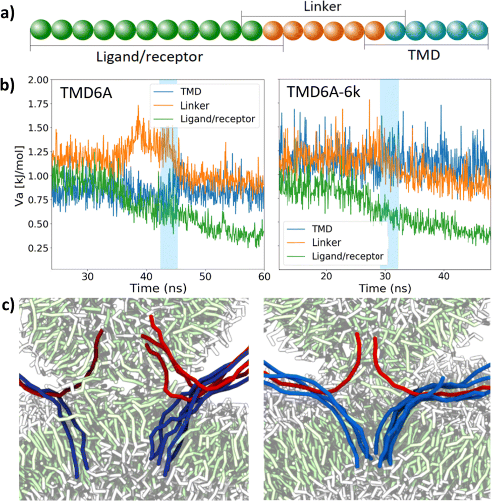 | ||
| Fig. 4 The effect of spike rigidity for anchored spikes. (a) The spike model is divided into three sections of which the mean bending potential is monitored separately: the ligand/receptor recognition domains, a linker, and the TMD including the trans-leaflet anchor. (b) The mean bending potential monitored during the simulations with TMD6A and TMD6A-6k spikes, normalized to the total number of angles per section of a spike. The blue shaded areas indicate the fusion from the formation of the hydrophobic bridge to the opening of the pore. (c) Snapshots showing the positioning, and bending, of the spikes in the stalk for the case of TMD6A (left) and TMD6A-6k (right) spikes. Lipids are coloured by bead type, ligand spikes in red and receptor spikes in blue. | ||
The bending potential peak in the linker before the fusion in the TMD6A case indicates that a substantial part of the bending energy is stored in this linker. In case of SNARE-proteins, the linker is believed to store the energy needed for a fast fusion development, which is subsequently used to exert force on the trans-leaflets of the membrane. This force pulls the lipids inside the stalk.69,88 A smaller or absent peak in this region, as can be seen in the rigid spike cases, means that the energy is not stored in one particular region, but more evenly distributed across the full length of the spike. This idea is confirmed by the fact that the bending potential in the anchor region is significantly higher during the fusion in the TMD6A-6k case. The resulting larger mechanical force acting on the membranes explains the decrease in fusion duration via especially a decrease of the duration of the stalk phase.
To examine the effect of rigidity of unanchored spikes on the fusion pathway, we also performed simulations of unanchored spikes with various bending potential force constants, analogous to the anchored spike case. The models we used are TMD8U-0k, TMD8U and TMD8U-6k. The fusion with fully flexible spikes (TMD8U-0k) again followed a slightly different pathway than with the regular flexibility (TMD8U). Rather than radially, the stalk expands anisotropically, after which it curls up to entrap a cluster of water beads in between the bilayer and the vesicle membrane. Eventually, the vesicle membrane breaks and the trapped water beads enter the vesicle, instantaneously leading to a hemifusion diaphragm. Here, the hemifusion diaphragm is formed by the bilayer membrane. Full fusion is not reached, since no fusion pore is formed within the 70 ns of this simulation. Comparison of the distance d* as a function of time in the TMD8U and TMD8U-6k simulations (Fig. 3d) shows that the general fusion pathway in both cases is similar, with an equal duration of the stalk phase. The duration of the hemifusion phase, however, is four times shorter in the TMD8U-6k case.
The results of these simulations with rigid unanchored spikes imply that the rigidity influences the duration and thus stability of the hemifusion diaphragm. Spikes with an increased rigidity are still able to position themselves horizontally in the stalk, causing no differences in this phase compared to the TMD8U case. Since rigid spikes are less able to fold themselves in the small cavities in the junctions of the hemifusion diaphragm, this phase is less stabilized, with a shorter duration as result. The TMD8U-0k situation led to a slightly different pathway, in which a cluster of water is trapped between both membranes. This might be caused by the maximum flexibility of the spikes. This flexibility perturbs the rigidity of the membrane packing in a way that it starts acting as a liquid, as we also saw in the case of flexible transmembrane spikes. This phenomenon causes the membrane to be flexible enough to trap water between both membranes. Due to the fluid-like structure, such a membrane is easily broken, after which the remaining membrane, in this case the bilayer, forms the hemifusion diaphragm. This phase appears to be stable enough to prevent the formation of a fusion pore. This last observation implies that the stability of the hemifusion diaphragm depends on the flexibility of the spikes, and their ability to fold themselves in the empty gaps in the hemifusion diaphragm.
Single spike-complex
Where all fusion simulations described so far considered a simulation box containing a vesicle with 30 ligands and a bilayer with 144 receptors, we next examine the minimum number and requirements of spikes needed for full fusion and whether simulations with fewer spike-complexes reproduce our findings concerning the pathway differences between anchored and unanchored spikes.Minimum requirements
To investigate the minimum number of spikes required for fusion, we performed simulations with TMD6A spikes in three different settings. Whereas the first setting contained a single ligand/receptor complex (L1R1), the second contained two complexes (L2R2) and the last setting contained two complexes as well, but with the possibility of clustering excluded (L2R2NC), i.e., one ligand interacts with only one receptor and vice versa. Fig. 5a shows the ligand/receptor complex in the final stage of the L1R1 simulation, in which the zipper was not fully closed. The L2R2NC simulation, resulted in two separate partially closed zippers (Fig. 5b). The L2R2 simulation resulted in a cluster of two fully closed zippers (Fig. 5c). Of these three simulations, only L2R2 led to a fusion within the duration of these simulations of 120 ns. | ||
| Fig. 5 Single spike simulations. (a–c) Snapshots of the ligand/receptor complexes at the final stage of a simulation with one TMD6A ligand and one receptor (L1R1), with two TMD6A ligands and two receptors without cross-interactions (L2R2NC), and with two TMD6A ligands and two receptors (L2R2) just before lipid protrusion occurs. Lipids are coloured by bead type, hydrophobic part of spikes in green, and remainder of spikes in purple. (d–f) Cross-sectional snapshots of fusion intermediates from simulations with a single ligand/receptor pair, with (d) rigid transmembrane spikes (TMD6A-6k) with increased ligand–receptor interaction, (e) rigid monotopic spikes (TMD8U-6k) with increased ligand–receptor interaction, and (f) transmembrane spikes (TMD6A) with a single completely flexible hinge. Lipids are coloured by bead type, ligand spikes in red and receptor spikes in blue. (g) Distance d* between water in the vesicle and below the bilayer as a function of time since lipid protrusion for the simulations in parts (d–f). | ||
Next, we increased the interaction strength εij between beads of the ligand and the receptor from 9 kJ mol−1 to 20 kJ mol−1 in the L1R1 simulation. This resulted in a fully closed zipper, but it did not initiate fusion within the 120 ns of the simulation. A simulation with the regular interaction parameter but an increased spike rigidity (TMD6A-6k spikes) did not lead to a fully closed zipper or a fusion either. Combining the enhanced interaction with an increased spike rigidity ensured that a hydrophobic bridge could be formed with a complete fusion reaction as result (Fig. 5d). To confirm the importance of a rigid linker, we repeated the last simulation with a single flexible angle at the transition of TMD to ligand/receptor. This resulted in a fully closed zipper with a kink at the location of the flexible angle (Fig. 5f) and did not lead to a fusion.
From the simulation results, we conclude that using a single ligand/receptor complex of our TMD6A spikes does not suffice to overcome the hydration barrier and complete the zipper, at least not within our simulation time, and that two complexes only suffice if they can form a cluster. This implies that the extra energy that is gained by this clustering behaviour is needed to complete the zipper. To obtain a closed zipper in the L1R1 simulation, the interaction parameter between spike beads had to be increased, but this only led to a fusion if the spike rigidity was increased as well. A simulation in which solely the rigidity was increased did not lead to a fusion, proving that both the increased interaction parameter and an increased rigidity are essential to initiate a successful fusion in the L1R1 case, in which closed zipper is needed to bring both membranes sufficiently close. The contribution of the increased rigidity may be explained by the findings of Kasson et al.57 that membrane proteins perturb the lipid packing of the membranes, therefore initiating lipid protrusion. These membrane perturbations might be essential for the initiation of a fusion reaction. A cluster of two zipper complexes seems to perturb this lipid packing enough to initiate lipid protrusion with a regular spike rigidity. A single zipper-complex requires a larger rigidity to achieve the same effect. A possible explanation is based on the higher tension that exists in more rigid spike complexes. This tension forces the TMD to be positioned under an angle with respect to the lipid packing, disturbing the lipid packing at a higher degree. However, if at least one angle in the linker is completely flexible, energy built up during the zipper process cannot be transferred to the TMD, making it impossible to perturb the membrane sufficiently to induce fusion.
Monotopic versus transmembrane
To verify the hypothesis that the same differences in fusion pathway between monotopic and transmembrane spikes can be discerned when using a single spike complex, we also performed simulations with a single monotopic TMD8U-6k ligand and receptor spike with the increased interaction strength of 20 kJ mol−1. Also this simulation, of which a snapshot of the stalk phase is shown in Fig. 5e, resulted in full fusion. In Fig. 5g we plotted the distance d* as a function of time from 1 ns before the stalk phase ends. Clearly visible in this graph, is the presence of a hemifusion phase in the monotopic spike case. The duration of this phase is six times shorter compared to the fusion with multiple monotopic spikes. Overall fusion took 5.5 ns in the transmembrane case, and 6.5 ns in the monotopic case. Both cases had a stalk phase of approximately 4 ns.Fig. 5g proves that even with a single zipper-complex the same differences in pathway can be discerned between fusion with transmembrane spikes and monotopic spikes, with a clearly visible hemifusion diaphragm in the TMD8U-6k case. This means that even a single spike can exert enough force on the trans-leaflets of the membranes to prevent the formation of a hemifusion diaphragm. The duration of the hemifusion phase is significantly shorter when using only one spike-complex compared to using multiple complexes. This difference is probably due to the number of TMDs available to fill the empty gaps in the junctions of the hemifusion diaphragm. Multiple TMDs can stabilize this phase for a longer period of time.
Shi et al.89 showed by means of experiments that a single SNARE-complex is sufficient to open a fusion pore at maximum rate. Our results corroborate that a single spike-complex is enough for a complete fusion. However, the duration of the stalk phase is significantly increased up to a maximum of ten times, compared to a fusion with multiple spikes. In the anchored situation, this difference is caused by the fact that a smaller force acts on the trans-leaflets. In the unanchored situation, this difference proves that multiple unanchored spikes can decrease the stalk duration, even if no force is directly exerted on the trans-leaflets. The results raise the idea that in case of a single transmembrane spike-complex, the spikes may need an even higher rigidity and probably a shorter TMD-length to increase force on the trans-leaflets, leading to a shorter stalk phase.
Conclusions
We used coarse grained molecular dynamics simulations to study the fusion of two biological membranes, mediated by fusion proteins (spikes), in which the membranes were modeled as a vesicle and a flat bilayer. To this end, we used spike models mimicking the general behavior of fusion proteins; bringing the membranes in close proximity and subsequently initiating and mediating the fusion. Ligand spikes on the vesicle and receptor spikes on the bilayer were modeled in a way that an attractive interaction between the two resulted in a zipper conformation, where spike properties as trans-leaflet anchoring, transmembrane domain length and rigidity could be varied systematically.We examined the fusion pathway of two distinct spike models; transmembrane spikes, having their TMD connected to the trans-leaflets of the membranes using a hydrophilic anchor, and monotopic spikes, lacking this hydrophilic anchor. Fusion with monotopic spikes proceeds through distinct phases with a clearly discerned stalk phase and hemifusion diaphragm phase. Fusion with transmembrane spikes proceeds more fluently, completely omitting the hemifusion diaphragm phase. We conclude that transmembrane spikes have an active role in fusion development, in which energy gained during the formation of the zipper is stored in the spike and subsequently used to exert force on the trans-leaflets of the membranes, consequently opening the fusion pore and preventing the formation of a hemifusion diaphragm.
The length of the TMD and rigidity of the spikes proved to be important properties in terms of force transmission across the length of the spike. Increasing the TMD length seems to lower the force exerted on the trans-leaflets, therefore increasing the duration of the stalk phase. Increasing the spike rigidity seems to lead to a larger force on the membrane, decreasing the duration of the stalk phase. Furthermore, an increased rigidity ensured that the bending energy was stored across the full length of the spike instead of solely in the linker. Unlike transmembrane spikes, monotopic spikes manage to stabilize the hemifusion phase, the degree in which this happens strongly depends on the rigidity of the spikes.
Finally, we hypothesized that similar pathway differences could also be discerned in simulations with a single spike complex. This hypothesis was confirmed, although these spikes needed an increased interaction between the ligand and the receptor to be able to fully close the zipper. Additionally, for fusion to occur, the rigidity proved to be a crucial property. A spike with a relatively high rigidity can perturb the lipid packing of the membranes sufficiently to initiate lipid protrusion, which is needed for the stalk to be formed. This protrusion will not occur spontaneously if the spikes are not sufficiently rigid. Fusion simulations with anchored and unanchored versions of these rigid spikes proved that the difference in fusion pathway does not depend on the number of spikes involved in the fusion. After all, the anchored spikes were still able to prohibit the formation of a hemifusion diaphragm. The total duration of the fusion, however, significantly increases when using a single spike-complex.
The conclusions suggest that for every fusion phase, different spike-properties are crucial. For the first phase, in which the membranes are brought in close proximity, the spikes have to be sufficiently flexible to be able to form the zipper conformation. Besides, the non-bonded interaction between ligand and receptor should be sufficiently large to overcome the hydration barrier. For the second phase, lipid protrusion and stalk formation, the lipid packing needs to be distorted. This can be achieved by multiple spikes, or by a single spike with sufficiently high rigidity. In the latter case, an increased rigidity of at least the linker is essential to induce a sufficient lipid distortion for a stalk to be formed. In case of monotopic spikes, the stability and duration of the hemifusion diaphragm strongly depend on the rigidity of the spikes. In case of transmembrane spikes, the stalk phase is directly followed by the opening of a pore. A large rigidity and a relatively short TMD length are needed to exert enough force to open the pore faster.
Our results are based on simulations of the fusion between a bilayer and a small vesicle. The chosen setup was selected to replicate the significant difference in curvature of a transport vesicle or a virus fusing with a cell membrane, whilst remaining computationally feasible when starting from an unbound state. This setup avoids potential artifacts that may result from initially placing the membranes already in close proximity or from fusing two highly curved membranes. However, the results may be dependent on the specific curvature of the vesicle membrane and the lipids used.
We used coarse grained models to mimic the general behavior of fusion proteins. The length of these spikes is based on the dimensions of SNARE-proteins. However, our models consist of only one linear strand, while fusion proteins in vivo typically consist of multiple domains,16 which might provide the rigidity and interaction strength required to yield fusion. An advantage of our model is that we were able to implement and systematically vary the rigidity without modeling multiple protein domains. On the other hand, by using models with a small thickness, we were not able to simulate and predict the behavior of the lipids in the presence of more complex proteins. To study such more complex proteins and/or the effect of lipid composition, a more detailed model would be needed. Yet, the straightforward tunability of ligand–receptor interactions in our model makes it useful to study possible effects of sliding and breathing by comparing highly specific receptor–ligand interactions, like for artificial fusion proteins based on DNA base pairing, to less specific ligand–receptor interactions that might be based on electrostatic and hydrophobic interactions. Moreover, by systematically varying the number of receptors and ligands, the model and simulation setup provided here seems a promising candidate to investigate possible synchronization between fusion proteins through mechanically coupling via the membrane.90
To conclude, fusion proteins need anchoring in the trans-leaflet to be able to obtain the shortest fusion duration, but since fusion proteins have to be multi-functional (bringing membranes together and mediating the fusion), for each fusion phase different properties are essential. This study gives perspective to further examine transmembrane spike fusion mechanisms. Larger vesicles must be used to examine the influence of membrane curvature and whether the fusion pathway changes when due to a larger contact area between the two membranes spike complexes have more freedom of movement. After all, from experimental data91 we know that even fusion with transmembrane spikes may proceed through a hemifusion phase if the distance between the spike complexes and the contact area of both membranes is large enough. In addition, the rigidity in single-spike experiments must be studied in closer detail. From our simulations we know that the optimal spike-rigidity depends on the fusion phase. Therefore, it may be useful to design spikes in which the rigidity differs in the various sections of the spikes. The ligand/receptor part should have a low rigidity to be able to form the zipper conformation, while the linker and the TMD should have a high rigidity to transmit the energy needed to open the fusion pore. This approach might increase the fusion speed in single-spike experiments. The results obtained during this study provide a better insight in the general mechanism of fusion proteins at the molecular level, and they can serve as handles for designing artificial spikes in biomimetic fusion systems.
Author contributions
PAJH and AJM conceptualized the study. PAMT performed the simulations and analysed the results. All authors discussed the results. PAMT and AJM wrote the manuscript with critical review by PAJH.Conflicts of interest
There are no conflicts to declare.References
- W. Stillwell, An Introduction to Biological Membranes: composition, structure and function, Elsevier, 2016, pp. 3–15 Search PubMed.
- H. Watson, Essays Biochem., 2015, 59, 43–69 CrossRef PubMed.
- L. V. Chernomordik and M. M. Kozlov, Annu. Rev. Biochem., 2003, 72, 175–207 CrossRef CAS PubMed.
- L. V. Chernomordik and M. M. Kozlov, Nat. Struct. Mol. Biol., 2008, 15, 675–683 CrossRef CAS PubMed.
- M. Miaczynska and M. Munson, Mol. Biol. Cell, 2020, 31, 399–400 CrossRef CAS PubMed.
- S. Modrow, D. Falke, U. Truyen and H. Schätzl, Molecular Virology, Springer Berlin Heidelberg, 2013, pp. 17–30 Search PubMed.
- F. A. Rey and S.-M. Lok, Cell, 2018, 172, 1319–1334 CrossRef CAS PubMed.
- D. S. Dimitrov, Nat. Rev. Microbiol., 2004, 2, 109–122 CrossRef PubMed.
- C. B. Wilen, J. C. Tilton and R. W. Doms, Cold Spring Harbor Perspect. Med., 2012, 2, a006866 Search PubMed.
- M. Luo, in Viral Molecular Machines, ed. M. G. Rossmann and V. B. Rao, Springer US, Boston, MA, 2012, pp. 201–221 Search PubMed.
- S. R. Weiss and S. Navas-Martin, Microbiol. Mol. Biol. Rev., 2005, 69, 635–664 CrossRef CAS PubMed.
- E. Schneck, F. Sedlmeier and R. R. Netz, Proc. Natl. Acad. Sci. U. S. A., 2012, 109, 14405–14409 CrossRef CAS PubMed.
- Y. A. Chen, S. J. Scales, S. M. Patel, Y.-C. Doung and R. H. Scheller, Cell, 1999, 97, 165–174 CrossRef CAS PubMed.
- J. Wesolowski and F. Paumet, Virulence, 2010, 1, 319–324 CrossRef PubMed.
- B. Alberts, A. Johnson, J. Lewis, M. Raff, K. Roberts and P. Walter, Molecular Biology of the Cell, W. W. Norton & Company, 2007 Search PubMed.
- L. J. Earp, S. E. Delos, H. E. Park and J. M. White, Current Topics in Microbiology and Immunology, Springer Berlin Heidelberg, 2004, pp. 25–66 Search PubMed.
- S. G. Peisajovich and Y. Shai, HIV gp41: A Viral Membrane Fusion Machine, in Viral Membrane Proteins: Structure, Function, and Drug Design. ed. W. B. Fischer, Protein Reviews, Springer, Boston, MA, 2005, Vol. 1 DOI:10.1007/0-387-28146-0_3.
- M. Kielian and F. A. Rey, Nat. Rev. Microbiol., 2006, 4, 67–76 CrossRef CAS PubMed.
- V. Marchi-Artzner, T. Gulik-Krzywicki, M.-A. Guedeau-Boudeville, C. Gosse, J. M. Sanderson, J.-C. Dedieu and J.-M. Lehn, Chem. Phys. Chem., 2001, 2, 367–376 CrossRef CAS PubMed.
- A. Richard, V. Marchi-Artzner, M.-N. Lalloz, M.-J. Brienne, F. Artzner, T. Gulik-Krzywicki, M.-A. Guedeau-Boudeville and J.-M. Lehn, Proc. Natl. Acad. Sci. U. S. A., 2004, 101, 15279–15284 CrossRef CAS PubMed.
- Y. Gong, Y. Luo and D. Bong, J. Am. Chem. Soc., 2006, 128, 14430–14431 CrossRef CAS PubMed.
- A. Kashiwada, M. Tsuboi, T. Mizuno, T. Nagasaki and K. Matsuda, Soft Matter, 2009, 5, 4719–4725 RSC.
- G. Stengel, R. Zahn and F. Höök, J. Am. Chem. Soc., 2007, 129, 9584–9585 CrossRef CAS PubMed.
- Y.-H. M. Chan, B. van Lengerich and S. G. Boxer, Proc. Natl. Acad. Sci. U. S. A., 2009, 106, 979–984 CrossRef CAS PubMed.
- P. M. G. Löffler, O. Ries, A. Rabe, A. H. Okholm, R. P. Thomsen, J. Kjems and S. Vogel, Angew. Chem., Int. Ed., 2017, 56, 13228–13231 CrossRef PubMed.
- A. S. Lygina, K. Meyenberg, R. Jan and U. Diederichsen, Angew. Chem., Int. Ed., 2011, 50, 8597–8601 CrossRef CAS PubMed.
- O. Ries, P. M. G. Löffler, A. Rabe, J. J. Malavan and S. Vogel, Org. Biomol. Chem., 2017, 15, 8936–8945 RSC.
- A. Kashiwada, K. Matsuda, T. Mizuno and T. Tanaka, Chem. – Eur. J., 2008, 14, 7343–7350 CrossRef CAS PubMed.
- H. Robson Marsden, N. A. Elbers, P. H. H. Bomans, N. A. J. M. Sommerdijk and A. Kros, Angew. Chem., 2009, 121, 2366–2369 CrossRef.
- K. Meyenberg, A. S. Lygina, G. van den Bogaart, R. Jahn and U. Diederichsen, Chem. Commun., 2011, 47, 9405–9407 RSC.
- F. Mazur and R. Chandrawati, Adv. Biosyst., 2019, 3, 1800330 CrossRef PubMed.
- F. Versluis, J. Voskuhl, B. van Kolck, H. Zope, M. Bremmer, T. Albregtse and A. Kros, J. Am. Chem. Soc., 2013, 135, 8057–8062 CrossRef CAS PubMed.
- N. S. A. Crone, D. Minnee, A. Kros and A. L. Boyle, Int. J. Mol. Sci., 2018, 19, 211 CrossRef PubMed.
- G. A. Daudey, H. R. Zope, J. Voskuhl, A. Kros and A. L. Boyle, Langmuir, 2017, 33, 12443–12452 CrossRef CAS PubMed.
- F. Versluis, J. Dominguez, J. Voskuhl and A. Kros, Faraday Discuss., 2013, 166, 349–359 RSC.
- T. Zheng, J. Voskuhl, F. Versluis, H. R. Zope, I. Tomatsu, H. R. Marsden and A. Kros, Chem. Commun., 2013, 49, 3649–3651 RSC.
- T. Zheng, M. Bulacu, G. Daudey, F. Versluis, J. Voskuhl, G. Martelli, J. Raap, G. J. A. Sevink, A. Kros and A. L. Boyle, RSC Adv., 2016, 6, 7990–7998 RSC.
- J. Yang, A. Bahreman, G. Daudey, J. Bussmann, R. C. L. Olsthoorn and A. Kros, ACS Cent. Sci., 2016, 2, 621–630 CrossRef CAS PubMed.
- L. Kong, Q. Chen, F. Campbell, E. Snaar-Jagalska and A. Kros, Adv. Healthcare Mater., 2020, 9, 1901489 CrossRef CAS PubMed.
- A. J. Markvoort and S. J. Marrink, Current Topics in Membranes, Elsevier, 2011, pp. 259–294 Search PubMed.
- H. J. Risselada and H. Grubmüller, Eur. Biophys. J., 2021, 50, 279–293 CrossRef CAS PubMed.
- S. J. Marrink and A. E. Mark, Biophys. J., 2004, 87, 3894–3900 CrossRef CAS PubMed.
- H. Leontiadou, A. E. Mark and S. J. Marrink, Biophys. J., 2004, 86, 2156–2164 CrossRef CAS PubMed.
- S. Ohta-Lino, M. Pasenkiewicz-Gierula, Y. Takaoka, H. Miyagawa, K. Kitamura and A. Kusumi, Biophys. J., 2001, 81, 217–224 CrossRef PubMed.
- V. Knecht and S.-J. Marrink, Biophys. J., 2007, 92, 4254–4261 CrossRef CAS PubMed.
- S. J. Marrink and A. E. Mark, J. Am. Chem. Soc., 2003, 125, 11144–11145 CrossRef CAS PubMed.
- M. J. Stevens, J. H. Hoh and T. B. Woolf, Phys. Rev. Lett., 2003, 91, 188102 CrossRef PubMed.
- J. C. Shillcock and R. Lipowsky, Nat. Mater., 2005, 4, 225–228 CrossRef CAS PubMed.
- P. M. Kasson, N. W. Kelley, N. Singhal, M. Vrljic, A. T. Brunger and V. S. Pande, Proc. Natl. Acad. Sci. U. S. A., 2006, 103, 11916–11921 CrossRef CAS PubMed.
- A. F. Smeijers, A. J. Markvoort, K. Pieterse and P. A. J. Hilbers, J. Phys. Chem. B, 2006, 110(26), 13212–13219 CrossRef CAS PubMed.
- A. Grafmüller, J. Shillcock and R. Lipowsky, Phys. Rev. Lett., 2007, 98, 218101 CrossRef PubMed.
- Y. G. Smirnova, S.-J. Marrink, R. Lipowsky and V. Knecht, J. Am. Chem. Soc., 2010, 132, 6710–6718 CrossRef CAS PubMed.
- D. Mirjanian, A. N. Dickey, J. H. Hoh, T. B. Woolf and M. J. Stevens, J. Phys. Chem. B, 2010, 114, 11061–11068 CrossRef CAS PubMed.
- A. J. Markvoort, A. F. Smeijers, K. Pieterse, R. A. Van Santen and P. A. J. Hilbers, J. Phys. Chem. B, 2007, 111, 5719–5725 CrossRef CAS PubMed.
- M. Fuhrmans and M. Müller, Soft Matter, 2015, 11, 1464–1480 RSC.
- K. Yang and Y. Ma, Soft Matter, 2012, 8, 606–618 RSC.
- P. M. Kasson, E. Lindahl and V. S. Pande, PLoS Comput. Biol., 2010, 6, e1000829 CrossRef PubMed.
- P. Larsson and P. M. Kasson, PLoS Comput. Biol., 2013, 9, e1002950 CrossRef CAS PubMed.
- J. H. Kim, T. L. Hartley, A. R. Curran and D. M. Engelman, Biochim. Biophys. Acta, Biomembr., 2009, 1788, 1804–1812 CrossRef CAS PubMed.
- V. Knecht and H. Grubmüller, Biophys. J., 2003, 84, 1527–1547 CrossRef CAS PubMed.
- M. Rabe, C. Aisenbrey, K. Pluhackova, V. de Wert, A. L. Boyle, D. F. Bruggeman, S. A. Kirsch, R. A. Böckmann, A. Kros and J. Raap, et al. , Biophys. J., 2016, 111, 2162–2175 CrossRef CAS PubMed.
- M. Fuhrmans and S. J. Marrink, J. Am. Chem. Soc., 2012, 134, 1543–1552 CrossRef CAS PubMed.
- H. J. Risselada, G. Marelli, M. Fuhrmans, Y. G. Smirnova, H. Grubmüller, S. J. Marrink and M. Müller, PLoS One, 2012, 7, e38302 CrossRef CAS PubMed.
- D. Milovanovic, A. Honigmann, S. Koike, F. Göttfert, G. Pähler, M. Junius, S. Müllar, U. Diederichsen, A. Janshoff and H. Grubmüller, et al. , Nat. Commun., 2015, 6, 1–10 CrossRef PubMed.
- S. Wu and H. Guo, J. Phys. Chem. B, 2009, 113, 589–591 CrossRef CAS PubMed.
- S. Baoukina and D. P. Tieleman, Biophys. J., 2010, 99, 2134–2142 CrossRef CAS PubMed.
- H. J. Risselada, C. Kutzner and H. Grubmüller, ChemBioChem, 2011, 12, 1049–1055 CrossRef CAS PubMed.
- A. Pabis, R. J. Rawle and P. M. Kasson, Proc. Natl. Acad. Sci. U. S. A., 2020, 117, 7200–7207 CrossRef CAS PubMed.
- S. Sharma and M. Lindau, Proc. Natl. Acad. Sci. U. S. A., 2018, 115, 12751–12756 CrossRef CAS PubMed.
- Y. G. Smirnova, H. J. Risselada and M. Müller, Proc. Natl. Acad. Sci. U. S. A., 2019, 116, 2571–2576 CrossRef CAS PubMed.
- H. J. Risselada, G. Bubnis and H. Grubmüller, Proc. Natl. Acad. Sci. U. S. A., 2014, 111, 11043–11048 CrossRef CAS PubMed.
- A. J. Markvoort, K. Pieterse, M. N. Steijaert, P. Spijker and P. A. J. Hilbers, J. Phys. Chem. B, 2005, 109, 22649–22654 CrossRef CAS PubMed.
- A. J. Markvoort, R. A. Van Santen and P. A. J. Hilbers, J. Phys. Chem. B, 2006, 110, 22780–22785 CrossRef CAS PubMed.
- A. J. Markvoort, P. Spijker, A. F. Smeijers, K. Pieterse, R. A. VanSanten and P. A. J. Hilbers, J. Phys. Chem. B, 2009, 113, 8731–8737 CrossRef CAS PubMed.
- D. Fasshauer, Biochim. Biophys. Acta, Mol. Cell Res., 2003, 1641, 87–97 CrossRef CAS PubMed.
- X. Lou and Y.-K. Shin, Biosci. Rep., 2016, 36(3), e00327 CrossRef CAS PubMed.
- Y. Park and J.-K. Ryu, FEBS Lett., 2018, 592, 3480–3492 CrossRef CAS PubMed.
- W. Humphrey, A. Dalke and K. Schulten, J. Mol. Graphics, 1996, 14, 33–38 CrossRef CAS PubMed.
- Y. Kozlovsky, L. V. Chernomordik and M. M. Kozlov, Biophys. J., 2002, 83, 2634–2651 CrossRef CAS PubMed.
- S. J. Scales, M. F. A. Finley and R. H. Scheller, Science, 2001, 294, 1015–1016 CrossRef CAS PubMed.
- J. M. Gardner and C. F. Abrams, J. Chem. Phys., 2017, 147, 134903 CrossRef PubMed.
- J. C. Shillcock, Methods in Molecular Biology, Humana Press, 2012, pp. 659–697 Search PubMed.
- Y. Xu, F. Zhang, Z. Su, J. A. McNew and Y.-K. Shin, Nat. Struct. Mol. Biol., 2005, 12, 417–422 CrossRef CAS PubMed.
- J. A. McNew, T. Weber, F. Parlati, R. J. Johnston, T. J. Melia, T. H. Söllner and J. E. Rothman, J. Cell Biol., 2000, 150, 105–118 CrossRef CAS PubMed.
- H. Xu, M. Zick, W. T. Wickner and Y. Jun, Proc. Natl. Acad. Sci. U. S. A., 2011, 108, 17325–17330 CrossRef CAS PubMed.
- J. Rohde, L. Dietrich, D. Langosch and C. Ungermann, J. Biol. Chem., 2003, 278, 1656–1662 CrossRef CAS PubMed.
- C.-W. Chang, C.-W. Chiang, J. D. Gaffaney, E. R. Chapman and M. B. Jackson, J. Biol. Chem., 2016, 291, 2848–2857 CrossRef CAS PubMed.
- H. J. Risselada and H. Grubmüller, Curr. Opin. Struct. Biol., 2012, 22, 187–196 CrossRef CAS PubMed.
- L. Shi, Q.-T. Shen, A. Kiel, J. Wang, H.-W. Wang, T. J. Melia, J. E. Rothman and F. Pincet, Science, 2012, 335, 1355–1359 CrossRef CAS PubMed.
- F. Manca, F. Pincet, L. Truskinovsky, J. E. Rothman, L. Foret and M. Caruel, Proc. Natl. Acad. Sci. U. S. A., 2019, 116, 2435–2442 CrossRef CAS PubMed.
- J. M. Hernandez, A. Stein, E. Behrmann, D. Riedel, A. Cypionka, Z. Farsi, P. J. Walla, S. Raunser and R. Jahn, Science, 2012, 336, 1581–1584 CrossRef CAS PubMed.
- P. Bassereau, R. Jin, T. Baumgart, M. Deserno, R. Dimova, V. A. Frolov, P. V. Bashkirov, H. Grubmüller, R. Jahn and H. J. Risselada, et al. , J. Phys. D: Appl. Phys., 2018, 51, 343001 CrossRef PubMed.
Footnote |
| † Current affiliation: Molecular Dynamics Group, Groningen Biomolecular Sciences and Biotechnology Institute, University of Groningen, The Netherlands. |
| This journal is © The Royal Society of Chemistry 2023 |