 Open Access Article
A highly transparent and photothermal composite coating for effective anti-/de-icing of glass surfaces†
Wei
Guo‡
ab,
Cui
Liu‡
ac,
Nian
Li‡
 ac,
Min
Xi
ac,
Yamin
Che
ab,
Changlong
Jiang
ac,
Min
Xi
ac,
Yamin
Che
ab,
Changlong
Jiang
 ac,
Shudong
Zhang
 *ac and
Zhenyang
Wang
 *ac
*ac
aInstitute of Solid State Physics, Hefei Institutes of Physical Science, Chinese Academy of Sciences, Hefei, Anhui 230031, China. E-mail: sdzhang@iim.ac.cn; zywang@iim.ac.cn
bDepartment of Chemistry, University of Science and Technology of China, Hefei 230026, China
cKey Laboratory of Photovoltaic and Energy Conservation Materials, Hefei Institutes of Physical Science, Chinese Academy of Sciences, Hefei 230031, China
First published on 11th May 2022
Abstract
Anti-/de-icing of glass surfaces is of great importance in present daily life. The long-standing challenge in this field is largely due to the lack of stable multifunctional coatings that can be conveniently and economically constructed on the glass surface, and more importantly, are capable of retaining the original transparency of glass ranging from the visible to the near infrared spectrum. Herein, a direct spraying sol method on the glass surface to prepare a highly transparent and photothermal composite coating is reported. Such multifunctional coating of Cu7S4 nanoparticles/organo-silicone sols has displayed a good photothermal conversion property and hydrophobic property and therefore yields excellent anti-icing and self-melting ice properties. The condensation time of water droplets can be extended to 86 s even at −10 °C, which is 3.42 times delayed relative to ordinary blank glass. And the adhesion strength of ice is largely reduced to 72 KPa, which is as low as ∼1/3 that of ordinary glass. Meanwhile, the subcooling of adhering droplets is reduced to −12 °C under one solar illumination condition and exhibits a rapid de-icing capability. More impressively, the prepared functional coating glass shows an outstanding transmittance of more than 75% in the visible region, while it is over the minimum glass transmittance limit allowed by Safety Standards for Glass (GB9656-2016, China). In addition, the multifunctional photothermal glass coating exhibits good physical/chemical stability, which facilitates the long-term application of the coating in different environments.
1. Introduction
Glass is an amorphous inorganic non-metallic material, the chemical composition including Na2SiO3, CaSiO3, SiO2 or Na2O–CaO–6SiO2, etc.,1 which is widely used for good transparency in buildings and other fields.2 Although the hydroxyl groups existing on the surface of fresh glass play an important role in its good hydrophilicity,3 the temperature difference between the inside and outside in winter will easily enable the droplets to cling on the glass surface and therefore condense to ice,4 which has a potential hazard in daily life.5 For example, icing on the car's front windshield will affect the visibility6 and the rapid change of temperature leads to bursting of the glass.7 On the one hand, the conventional passive compromised solutions for anti/de-icing on the glass surface mainly reduce the glass surface energy by glass hydrophobic surface modification. The organo-fluorine coating prevents the droplets from adhering to the glass surface, but once frozen, the anti/de-icing capability of organo-fluorine coating fails. Meanwhile, the organo-fluorine coatings break down easily and are unfriendly to the environment due to their non-degradability,8 which is often the main reason for limiting their application. On the other hand, for developing an effective way to achieve an anti/de-icing coating for glass, the preparation of transparent electric heating films by doping with SnO2 has been used for glass de-icing.9,10 Transparent conductive glass has a good de-icing ability due to the electrical input, but the preparation technology is high demanding and uneconomical.11Photothermal conversion coating is a promising material for anti/de-icing of glass surfaces.12–14 Various photothermal materials, including functional inks from cuttlefish,15 carbon-based materials,16–18 metal ceramics,19 CVD-deposited graphene,20,21 and carbon nanotubes,14,22,23 have been used in research studies to develop anti/de-icing surfaces. Currently, these photothermal conversion coatings are typically applied in anti/de-icing studies of aircraft wings,24–26 large equipment,27,28 and under other particularly extreme environmental conditions.29 Different from what is mentioned above, the transmittance of the coating used for glass surface de-icing is an important factor be taken into account. Therefore, the development of a highly transparent, hydrophobic and photothermal conversion composite coating is an effective way to achieve an anti-/de-icing coating for glass.
Herein, a transparent glass coating with an anti/de-icing effect to address the aforementioned issues is prepared by a direct spraying method. The aqueous modified Cu7S4 photothermal nanoparticles can be uniformly dispersed in the prepared silicone sol. After direct spraying on the glass surface, the surface temperature of the coated glass with a very low Cu7S4 photothermal nanoparticle concentration (∼0.2 wt%) can be increased by about 10 °C relative to normal glass under one solar illumination condition. At the same time, the coating can effectively improve the hydrophobicity of the glass and increase the contact angle (CA) of the surface to 121.8°, which results in good anti-/de-icing performance while ensuring that the visible light transmission rate of the glass exceeds 75%. On the one hand, coated glass can delay the icing time of liquid droplets. On the other hand, it can reduce the adhesion between ice and glass. In addition, the coated glass can not only reduce the starting freezing temperature of droplets on the glass surface to −12 °C under light conditions, but also enable rapid removal of surface ice caps in low temperature environments, which has a potential application in fields such as architectural glass and automobiles.
2. Results and discussion
2.1 Preparation and morphology of the transparent, hydrophobic and photothermal coating
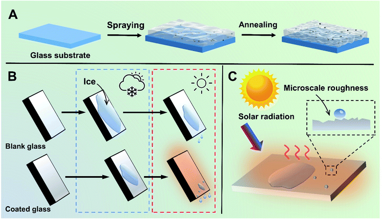
The preparation process of the transparent, hydrophobic and photothermal composite coating is shown in Fig. 1A. First, fresh glass is washed with H2SO4/H2O2 as the substrate with abundant hydroxyl groups. Then, Cu7S4 photothermal nanoparticles modified with PSI-OAm are mixed with silicone sol and sprayed on the surface of the glass substrate with hydroxyl groups, and further annealed at high temperature to enhance the bonding between the coating and the glass. Finally, highly transparent, hydrophobic and photothermal composite coating can be successfully anchored on the surface of the ordinary glass.It is well-known that water vapor in the air can condense and adhere on an ordinary glass surface at low temperatures, further freezing into ice. Herein, the photothermal composite coating can effectively retard this process following two main considerations. On the one hand, it can reduce the adhesion of liquid droplets on the glass surface owing to the good hydrophobicity, which can delay the condensation of liquid droplets on the glass surface. On the other hand, even if icing occurs on the glass coating surface under harsh temperature conditions, the photothermal coating glass has a rapid solar-to-heat conversion property and can thus realize faster ice melting effect compared to normal glass under light conditions (Fig. 1B and C).
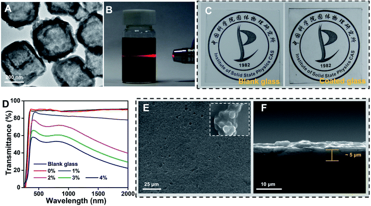
Starting from a photothermal material, we firstly prepared cube-like and hollow Cu7S4 nanoparticles with ∼250 nm average width (Fig. S1A and B, ESI†), reaching a high photothermal conversion effect of 36.2% (Fig. S2A and B, ESI†).32 Secondly, in order to obtain water-dispersed Cu7S4 nanoparticles, PEI-OAm was chosen to successfully modify the Cu7S4 nanoparticle surface (corresponding XRD pattern and IR spectra are shown in Fig. S3A and B, ESI†). The TEM image shows that the Cu7S4 nanoparticles after PEI-OAm modification retain the obvious hollow and stable structure (Fig. 2A). Next, we were able to achieve easy dispersion of the modified Cu7S4 nanoparticles into the SiO2 hydrosol in the range of concentrations from 0.1 to 0.4 wt% by varying the mass loading of the modified Cu7S4 nanoparticle dispersion (Fig. S4, ESI†). The well-defined Tyndall effect of a colloidal solution of the modified Cu7S4 nanoparticles indicates the presence of highly monodisperse Cu7S4 nanoparticles in SiO2 hydrosol (Fig. 2B). The colloidal suspension was very stable and homogeneous, and no aggregation was observed upon standing for more than a week, which is different from the unmodified Cu7S4 nanoparticles/hydrosol dispersion (Fig. S5, ESI†). We found that a direct spraying sol method on the glass surface results in a uniform and highly transparent coating surface (Fig. 2C) when using a well-dispersed aqueous hydrosol suspension of the modified Cu7S4 nanoparticles as the precursor. The prepared functional coating glasses showed a variable transmittance in the visible region from 91.4% to 53.2% that varies with the doping concentration of Cu7S4 nanoparticles from 0 to 0.4 wt% (Fig. 2D), respectively. For example, when the doping concentration of Cu7S4 nanoparticles is 0.2%, the functional coating glass can maintain a good transmittance relative to the blank glass (Fig. 2C), and the transmittance of the coating in the visible region remains over 76.2% (Fig. 2D), which meets the transparency requirements of the glass standard (75%, GB9656-2016, China). Meanwhile, the functional coating surface is uniformly smooth (Fig. 2E) and the thickness of the coating is about 5 μm (Fig. 2F) as determined by observing the surface and cross-section of the coating by SEM. On further magnifying the coating surface we found that fine SiO2 particles with a diameter of ∼80 nm had gathered resulting in nano-scale roughness (inset picture of Fig. 2E) like a hydrophobic structure on the surface of a lotus leaf. Such nano-scale coarseness of the functional coated surface further improves the transmittance due to the increased diffuse reflectance.33
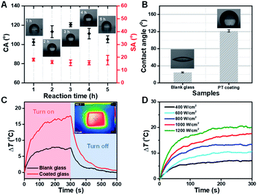
Obviously, a nano-scale rough surface can enhance the hydrophobic properties of the coating. And the hydrophobic property of the coating will further affect the anti-fogging performance of the functional coating glass. We found that the hydrolysis time of TEOS generating SiO2 nanoparticles plays a role in the hydrophobic performance of the coating. Here, the optimal hydrolysis time of TEOS was 3 h. Too little or too long hydrolysis time was not conducive to a good hydrophobic surface (Fig. S6, ESI†). And the CA of the functional coating reaches a maximum of 121.8° with TEOS hydrolysis time at 3 h (Fig. 3A). Therefore, the functional coating glass shows excellent hydrophobic property (Fig. 3B) compared with ordinary glass (CA = ∼28.0°). In addition, the effect of other components on the hydrophobicity of the coatings has been investigated, and the doping concentration of PU and coating thickness have been found to be the main influencing factors (Fig. S8, S9 and S10 ESI†). However, it should be noted that the increase in coating thickness will reduce the adhesion of the coating.
As is well known, ordinary transparent glasses have almost no light–heat conversion capacity, in that sunlight can easily pass through them. Ordinary glass surface temperature can increase only up to 7.6 °C relative to the room temperature under one solar illumination condition. Herein, impressively, the functional glass (only 0.2 wt% of Cu7S4 photothermal nanoparticles) surface temperature can increase rapidly up to 17.4 °C under the same condition, and the temperature difference between the two types of glass reaches nearly ∼10 °C (Fig. 3C). And the functional photothermal coating also has a very good thermal cycling stability (Fig. S7, ESI†). The thermal IR images of the functional coating glass were nearly uniform, suggesting that the photothermal Cu7S4 NP coating was equally distributed on the ordinary glass surface without aggregation (inset image of Fig. 3C). Furthermore, we also investigated the sunlight power density and temperature change correlation of the functional photothermal coating. With the increase of light power, the temperature on the surface of the coating also increases gradually (Fig. 3D). The above results show that the functional photothermal coating has a rapid and good photo-thermal conversion ability.
2.2 Anti-icing performance
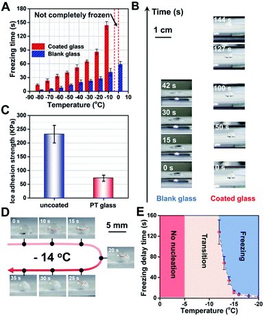
Next, the hydrophobic and photothermal properties of the obtained multifunctional coating glass were systematically studied to deeply understand the essence of the anti-icing performance. Firstly, the anti-icing performance of the functional coating glass and the blank glass at different ambient temperatures is discussed. It is noteworthy that a 5 μL droplet on the surface of the functional coating glass always maintains an incomplete solidification state at 0 °C in a long time. In contrast, the same dose of droplet on the surface of blank glass freezes in 60 s. When the cooling down was continued to −10 °C, it takes about 144 s for the droplet dropping on the coating glass surface to freeze fully, which is 3.42 times delay in the rate of ice condensation relative to that of the blank glass (∼42 s of ice time). At other lower temperatures, all multifunctional coating glasses show slower water freezing times (Fig. 4A). Therefore, we can conclude that the coating can effectively improve the hydrophobicity of the glass surface and thus achieve good anti-icing performance. Moreover, the effect of different components on the anti-icing performance of the coating is discussed and it is further demonstrated that the hydrophobicity of the coating significantly affects the anti-icing performance of the coating (Fig. S11, ESI†).Secondly, to further understand the icing process and state, we captured digital photos of the droplet's changing process at −10 °C on coated glass and blank glass surfaces (Fig. 4B), respectively. When a 5 μL droplet is dropped on the coated glass surface, the water droplet with ∼3 mm height immediately forms on the coating surface due to the hydrophobic effect on the coated glass surface. In contrast, a flat drop of water with ∼1 mm height slowly forms on the blank glass surface, that is, the hydrophilicity leads to a greater contact area. As time goes by, in a 42 second split-second period, the flat water droplet transforms into ice and undergoes a liquid–solid phase change on the blank glass surface. Differently, the gradual formation of ice nuclei at the droplet–glass interface can be observed at about 127 s and finally they freeze completely at 144 s on the coated glass surface. Obviously, improving the hydrophobicity of the glass surface and thus reducing the contact area of water droplets will be very beneficial to ice resistance, which is consistent with the classical Cassie–Baxter state at the hydrophobic interface.11,34 Besides, we had also investigated the ice adhesion strength of the functional coating glass and the blank glass in the same “contact area” shown in Fig. 4C (see the anti-icing performance test in the ESI†). The ice adhesion strength of the photothermal coating is only 72 KPa and the blank glass is about 232 KPa, which is as low as ∼1/3 that of ordinary glass. It can be attributed to the fact that the hydrophobicity of the functional photothermal coating can effectively reduce the ice-crystal adhesion strength. Coated glass can effectively reduce the freezing of water on its surface by slowing down the condensation time of water and its adhesion after freezing, which is conducive to the anti-icing of glass in a low temperature environment. Furthermore, the doping concentration of PU and the coating thickness had a significant effect on the adhesion strength of the ice on the coatings, which is related to the hydrophobicity of the coating (Fig. S12, ESI†).
Thirdly, the anti-icing performance of the functional photothermal coating is simulated for the daytime light conditions. We first placed the samples in a cryogenic cold well, set a certain temperature and then kept it for 30 min to ensure the thermal equilibrium of the environment, finally, simulated sunlight with solar illumination was used for 5 min. We can find that a 5 μL droplet on the surface of the functional coating glass always maintains an incomplete solidification state when the temperature is higher than −12 °C. And under one solar illumination condition, we optimized −14 °C to further observe the freezing behavior of water droplets (Fig. 4D). During this period, the process of solid phase formation (∼10 s), gradual unfolding (∼25 s), and the formation of a tip at the top of the droplet at about 35 s can be clearly observed, which is obviously different from the above phenomenon (rapid freezing (∼5 s) of the droplet at −10 °C ambient temperature, no illumination). The freezing process of the droplet under one solar illumination is divided into two phases: nucleation and crystallization. In addition, the droplet states at different temperatures are investigated under one solar illumination (Fig. 4E). Higher than −5 °C, the droplet doesn't change at all. From −5 °C to −12 °C, a number of small ice nuclei were floating rapidly upwards within the droplet. When the temperature drops below −12 °C, the droplets freeze completely. Consequently, the above experimental results show that the functional photothermal coating can effectively reduce the subcooling of water under solar irradiation and thus prevent its freezing.
2.3 Ice melting characteristics of the coating
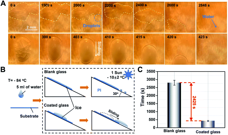
To further explore the advantages of the functional photothermal coated glass, de-icing the ice block that was formed from larger doses of water droplets (5 mL) was performed for comparison between the blank glass and functional coated glass mounted with a tilt angle of 30° (Fig. 5A and B). In the case of the the blank glass, the ice cap retained its original state during a period of 1500 s and the volume of the ice cap gradually decreased with the ice melt at about 2000 s. Furthermore, we observed that the unmelted ice cap floats in the water and starts to slide at about 2400 s, and finally slides off completely at 2848 s. However, a water residue clinging on the blank glass surface (top-view image at 2848 s in Fig. 5A) could still be observed, which poses the risk of secondary freezing. In contrast, in the case of the functional photothermal coating glass, the self-heating effect of the coating under sunlight conditions leads to a rapid increase in the glass surface temperature, which accelerates the melting of the ice. At the same time, the surface hydrophobic property will make it difficult for the ice cap to stay on the glass surface after melting. It is worth noting that when the ice cap starts to melt, it will immediately move and slide off due to the very little adhesion from the surface hydrophobicity. As a result, the whole process takes about 20 s from the start of the ice cap sliding down, and it completely slides off at 423 s. Side views of the ice melting process are shown in Fig. S14 and S15.† Finally, a statistical analysis of the water melting time on the two kinds of different surfaces (Fig. 5C) shows that the functional coated glass can increase the melting rate of ice by about 6.73 times compared to ordinary glass due to the excellent photothermal/hydrophobic synergy. In a word, the designed functional coating can accelerate the melting rate of ice and prevent it from staying on the glass surface, thus showing excellent de-icing ability. Besides, the amount of Cu7S4 doping is the main factor influencing the rate of de-icing (Fig. S13, ESI†). Although the increase in the doping concentration of nanoparticles can significantly improve the fast de-icing ability of the coating, the doping number of nanoparticles was limited to 0.1 wt% because of the requirement of glass coating permeability.2.4 Stability of the coating
The physical/chemical stability of the functional photothermal coating is important for the applications in different environments. Acid/alkali resistance (Fig. 6A), aging resistance (Fig. 6B) and cycling stability (Fig. 6C) under −30–30 °C operating conditions, and wear resistance (Fig. 6D) were evaluated, respectively. The test results indicate that there are little effects of different pH conditions, different aging times, cold/heat cycles, and wear resistance after abrasion by fine sand on the functional photothermal coating. And the CA of the coating is always maintained around ∼120° while maintaining a good photothermal conversion and mechanical durability, which has great potential for practical applications.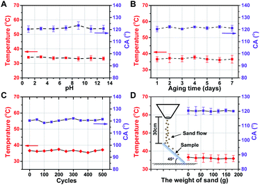 | ||
| Fig. 6 Photothermal conversion and CA of the coating treated with (A) different pH solutions, (B) aging test, (C) −30–30 °C cycles, (D) sand impact cycles, respectively. | ||
3. Conclusions
In summary, a direct spraying sol method has been successfully developed to prepare a highly transparent and photothermal composite coating on the glass surface. The obtained Cu7S4/organo-silicone sol coating has high transparency, excellent photothermal conversion, effective anti/de-icing behavior, and super chemical/physical stability. This strategy of integrating photothermal conversion materials and silicone sols into one coating provides a huge possibility for future multifunctional material applications in automotive and construction fields.4. Experimental
4.1 Chemicals and materials
All the chemicals were used without further purification. Copper(II) acetate monohydrate (Cu(CH3COO)2·H2O), sodium hydroxide (NaOH), vitamin C (VC), polyvinylpyrrolidone (PVP, K-30), sodium sulfide (Na2S·9H2O), polysuccinimide (PSI, 7000–8000, 99%), oleylamine (80–90%), tetraethyl orthosilicate (TEOS, 98.0%), and ammonium hydroxide (NH3·H2O, 28%) were purchased from Aladdin Group Chemical Reagent Co., Ltd. Sulfuric acid (H2SO4, 70%) and acetic acid (CH3COOH, 36%) were purchased from Sinopharm Chemical Reagent Co., Ltd. Water-based PU was purchased from Hengyuan Chemical Co., Ltd (Guangzhou, Guangdong).4.2 Treatment of the glass substrate
The glass substrate was soaked in H2SO4/H2O2 for 2 hours first, then it was washed with absolute ethanol and deionized water three times and placed in an infrared drying box for further use.4.3 Preparation of Cu7S4 photothermal nanoparticles
Cu7S4 photothermal nanoparticles were synthesized according to our previous work.30 0.2 g of polyvinylpyrrolidone and 0.2 g of Cu(CH3COO)2·H2O were dissolved in 30 mL of deionized water and stirred for 30 min, then 10 mL of NaOH (1 M) aqueous solution was added and the stirring was continued for 30 min. When a blue precipitate appeared in the solution, 10 mL of ascorbic acid (0.3 M) aqueous solution was quickly added to the mixed solution, heated to 55 °C and stirred for another 30 min. After a brick red precipitate appeared, 20 mL of Na2S·9H2O (0.15 M) was added and stirred continuously at 55 °C for 1 hour. After the reaction was complete, the mixed solution was cooled to room temperature, and the product was washed with deionized water and absolute ethanol by centrifugation 3–4 times, and dried in a vacuum oven overnight finally.4.4 Preparation of water dispersed Cu7S4 photothermal nanoparticles
1 g of PSI was dissolved in 20 mL of DMF and stirred at 60 °C until complete dissolution. Then 1 mL of oleylamine was added, and the reaction mixture was kept at 60 °C for 12 h. After the reaction, methanol was added and the precipitate was collected by centrifugation, and the product was finally dissolved in chloroform and configured as a 20 mg mL−1 PSI-OAm/chloroform solution. After 5 mg of Cu7S4 photothermal nanoparticles were dispersed in 20 mL of water, 5 mL of the PSI-OAm/chloroform solution was added, sonicated for 2 h and then the product was collected by centrifugation to obtain water-dispersed Cu7S4 photothermal nanoparticles.4.5 Preparation of photothermal coating
4.475 mL of TEOS was added to 18 mL of deionized water and 9.32 mL of ethanol. The pH was first adjusted to 4–5 with 0.1mol L−1 glacial acetic acid under magnetic stirring several times (1 h, 2 h, 3 h, 4 h, and 5 h), then the pH of the solution was adjusted to 7 with 0.1 mol L−1 of ammonia. The water dispersed Cu7S4 was added and sonicated for 15 min, and a certain amount of 1 wt% aqueous PU was added, stirring for 15 min at room temperature finally.The mixed suspension was spray-coated onto a glass slide using an airbrush at 60 psi with a distance of about 15 cm. The moving speed of the spray nozzle was adjusted at 100 mm s−1. Then the coating was cured at 110 °C for 1 h. And the spraying process was repeated 5 times for each sample.
4.6 Surface morphology and chemical composition characterization
X-ray diffraction patterns of Cu7S4 photothermal nanoparticles were obtained using an X-ray energy spectrometer (PANalytical, X'Pert), SEM images were obtained using a focused ion beam scanning electron microscope (SU8020 field emission scanning electron microscope), TEM images of Cu7S4 modified by PSI-OAm were obtained using a field emission transmission electron microscope (JEM-2100F), and the Fourier infrared spectrum of the composite coating was obtained using a Fourier infrared spectrometer (iS50R FT-IR), respectively. The transmission spectrum and absorption spectrum of the composite coating were obtained using an ultraviolet-visible-near-infrared spectrophotometer (Shimadzu, SOLID3700).4.7 Wettability measurement
The contact angle (CA) of the samples was measured by using a CA meter (Dataphysics, OCA25) with a 2.2 μL drop of deionized water at ambient temperature (∼5 °C). Each sample was tested at least five times on different locations to evaluate the CA.4.8 Photothermal conversion performance test
Simulated sunlight was provided by a steady-state solar simulator (Saifan, 7IS1003A). Temperature changes on the sample surface under light conditions were recorded by using the matched temperature sensing device. The intensity of the simulated sunlight was measured using a solar power meter (TES 132). And a portable FT-IR (FLUKE TiS75+) infrared thermal imaging camera was used for infrared imaging.4.9 Anti-icing performance test
The anti-icing performance of the coating was evaluated by testing the freezing time of the droplets on the sample surface. The sample was placed on the hot and cold table (HCS621GXY) after droplets of 5 μL were naturally dropped on the sample surface, and the temperature range of the hot and cold table was set at −80 °C to 0 °C. A digital camera is used to record the process of complete freezing of the droplet while a stopwatch is used to record the time. The time from the start of placing the sample on the hot and cold table to the complete transformation of the droplet into the solid phase is defined as the freezing time.The ice adhesion strength test was carried out with reference to the literature,16 by using a cylinder with a diameter of 1 cm and a height of 1 cm to create an ice column on the surface of the sample. The sample was placed in the ice freezer with the temperature and relative humidity set at −20 °C and 40%, respectively. Afterwards, the ice column was pushed using a digital spring dynamometer and the force (Fm) required for the ice column to slide down was recorded, after which using the equation τice = Fm/Aice, τice was determined, where τice is the attachment strength of the icicle and Aice is the bottom area of the icicle.
4.10 Anti-icing test under illumination conditions
Different from the above experiments, anti-freezing tests under light conditions were carried out in a custom-made cryogenic cold well; firstly, the samples were placed and kept under different temperature conditions for 30 min. Then the sample surface was irradiated with sunlight with one solar illumination for 5 min. Finally, the 5 μL droplets were dropped on the sample surface and kept under light to observe the freezing process of the droplets.4.11 Photothermal deicing test
First, 5 mL of water was dropped on the surface of the sample naturally and then placed in a refrigerator (−84 °C) to freeze it to ice. Second, a platform with a 30° tilt angle and a 1 mm projection on the surface of the platform to prevent the glass from slipping was printed by using 3D printing technology. Finally, the samples were removed from the refrigerator and placed under a solar simulator with one solar illumination vertically at an ambient temperature of −10 ± 2 °C to observe the changes of the ice layer on the sample surface.4.12 Aging test
The aging test was done in a UV aging chamber of a full performance dye-sensitized solar cell aging system (Borealis, BR-PV). The classical double ‘85’ test method is used, i.e.31 the temperature/humidity inside the chamber is set at 85 °C/85% under UV light irradiation. The CA and photothermal conversion performance of the samples are tested to evaluate the aging resistance of the samples.4.13 Coating abrasion resistance test
The abrasion resistance of the coating was tested by impacting the sample surface with fine sand. Referring to the method in the literature,16 in the sand impact test, a continuous stream of sand grains falls from a height of 30 cm and impacts the surface of a 30° inclined sample. Then the CA and photo-thermal conversion properties of the coatings were tested.4.14 Coating chemical stability test
Aqueous solutions with different pH values were configured with NaOH and H2SO4, the samples were subsequently immersed and kept for 6 h and then removed to test their CA and photothermal conversion properties.4.15 Coating cycling stability test
The samples were placed in a cold table and the cold table temperature was set to a −30–30 °C cycle; after every 50 cycles the samples were taken out to test the CA and photothermal conversion characteristics.4.16 Adhesion test
The adhesion test of the coating is carried out by method B – orthogonal notch tape test in ASTM D3359.34–40 After spraying the coating evenly on the surface of the glass substrate, the sample was placed on a horizontal platform. The coating surface was cut with a cutting tool at a cutting speed of (15–25) mm s−1 to make 6 strips in the axial and longitudinal directions of the glass substrate, respectively. According to the requirement, the cuts are separated by 1 mm when the dry film thickness is lower than 50 μm. The cutting tool should cut forcefully and appropriately to make the scratches penetrate in order to touch the glass substrate when making the incisions, then tape was applied to the surface of the coating, and the tape was torn off evenly (keeping the level at 180° when tearing off the tape), and subsequently the sample was placed under a microscope to observe the evaluation of the coating peeling.Author contributions
Zhenyang Wang and Shudong Zhang conceived and designed the method, and thus edited and wrote the work. Wei Guo, Cui Liu, Nian Li, Min Xi, and Yamin Che performed the experiments and analyzed the data. All authors have read and approved the final manuscript.Conflicts of interest
There are no conflicts to declare.Acknowledgements
This research was supported by the National Key Research and Development Project (2020YFA0210703), the National Natural Science Foundation of China (Nos. U2032158, U2032159, and 62005292), the Major Scientific and Technological Special Project of Anhui Province (202103a05020192), the Key Research and Development Program of Anhui Province (202104a05020036), the Special fund project for local science and technology development guided by the central government of Anhui Province (202107d08050016), Collaborative Innovation Program of Hefei Science Center, CAS (2020HSC-CIP003), the Major Scientific and the CASHIPS Director's Fund (YZJJZX202015), and the technological Innovation Projects of Shandong Province (2019JZZY020243).Notes and references
- Q. Halim, N. A. N. Mohamed, M. R. T. Rejab, W. Naim and Q. J. Ma, Int. J. Adv. Manuf. Tech., 2021, 112, 1231–1258 CrossRef.
- D. A. Barcelos, D. C. Leitao, L. C. J. Pereira and M. C. Goncalves, Materials, 2021, 14, 2926–2955 CrossRef CAS PubMed.
- K. Y. Cheng, W. F. Wang, M. C. Wu and K. C. Hsieh, Jpn. J. Appl. Phys., 2020, 59, 0709011–0709015 Search PubMed.
- M. H. Kim, H. Kim, K. S. Lee and D. R. Kim, Energy Convers. Manage., 2017, 138, 1–11 CrossRef.
- S. S. Latthe, R. S. Sutar, A. K. Bhosale, S. Nagappan, C. S. Ha, K. K. Sadasivuni, S. H. Liu and R. M. Xing, Prog. Org. Coat., 2019, 137, 105373–105390 CrossRef CAS.
- K. R. Khedir, G. K. Kannarpady, C. Ryerson and A. S. Biris, Prog. Org. Coat., 2017, 112, 304–318 CrossRef CAS.
- H. F. Liu, S. C. Zhang, Y. Q. Jiang and Y. Yao, Sol. Energy, 2015, 112, 144–153 CrossRef.
- M. J. Na, H. Yang, H. J. Jung and S. D. Park, Surf. Coat. Technol., 2019, 372, 134–139 CrossRef CAS.
- H. Huang, O. K. Tan, Y. C. Lee and M. S. Tse, J. Cryst. Growth, 2006, 288, 70–74 CrossRef CAS.
- T. Fukano and T. Motohiro, Sol. Energy Mater. Sol. Cells, 2004, 30, 567–575 Search PubMed.
- T. Chang, O. A. Moses, C. Tian and H. Wang, Adv. Sci., 2021, 8, 2003387–2003400 CrossRef CAS PubMed.
- Y. B. Liu, Y. Wu, S. J. Liu and F. Zhou, ACS Mater. Lett., 2016, 74, 246–262 CrossRef.
- W. R. Zhao, L. Xiao, X. Y. He, Z. H. Cui, J. H. Fang, C. Zhang, X. H. Li, G. Q. Li, L. Zhong and Y. B. Zhang, Opt. Laser Technol., 2021, 141, 107115–107127 CrossRef CAS.
- G. Jiang, L. Chen, S. D. Zhang and H. X. Huang, ACS Appl. Mater. Interfaces, 2018, 10, 36505–36511 CrossRef CAS PubMed.
- Y. D. Yan, N. Z. Luo, X. G. Xiang, Y. M. Xu, Q. H. Zhang and X. L. Zhan, Prog. Chem., 2014, 26, 214–222 CAS.
- C.-H. Xue, H.-G. Li, X.-J. Guo, Y.-R. Ding, B.-Y. Liu, Q.-F. An and Y. Zhou, Chem. Eng. J., 2021, 424, 130553–130563 CrossRef CAS.
- V. S. Saji, Nanotechnol. Rev., 2021, 10, 518–571 CrossRef CAS.
- H. Li, C. Xue and S. Jia, Fine Chem., 2021, 38, 934–940 Search PubMed.
- Z. T. Xie, H. Wang, Y. Geng, M. Li, Q. Y. Deng, Y. Tian, R. Chen, X. Zhu and Q. Liao, ACS Appl. Mater. Interfaces, 2021, 13, 48308–48321 CrossRef CAS PubMed.
- Y. Wu, W. Zhao, W. Wang, Y. Zhang, L. Li and Q. Xue, Surf. Technol., 2017, 46, 133–145 Search PubMed.
- X. Wang, S. Wei, X. Zhu, B. Wang, L. Guo, Y. Wang, Y. Liang and B. Xu, Chin. J. Eng., 2021, 43, 332–344 CAS.
- P. Govindaraj, B. Fox, P. Aitchison and N. Hameed, Ind. Eng. Chem. Res., 2019, 58, 17106–17129 CrossRef CAS.
- S. Nagappan, S. S. Park and C. S. Ha, J. Nanosci. Nanotechnol., 2014, 14, 1441–1462 CrossRef CAS PubMed.
- J. Xu, X. Gong and S. Ramakrishna, Nanotechnology, 2021, 137, 127191–128216 Search PubMed.
- D. Jia, L. Li and Y. Li, Chemistry, 2015, 78, 483–488 CAS.
- K. Chen, Q. Wang and Z. Xia, Appl. Chem. Ind., 2016, 45, 1969–1973 Search PubMed.
- H. Li, Y. H. Zhao and X. Y. Yuan, Prog. Chem., 2012, 24, 2087–2096 CAS.
- O. Parent and A. Ilinca, Cold Reg. Sci. Technol., 2011, 65, 88–96 CrossRef.
- Y. Wu, X. Li, C. Mi, L. Zong, X. Wang, K. Guo and F. Song, Surf. Technol., 2018, 47, 51–59 Search PubMed.
- T. T. Xu, S. D. Zhang and S. Han, Ind. Eng. Chem. Res., 2021, 60, 5869–5878 CrossRef CAS.
- M. He, H. Dong, X. Jin and M. Yimit, China Plast. Ind., 2021, 49, 1–6 Search PubMed.
- D. Shin, G. Kang, P. Gupta, S. Behera, H. Lee, A. M. Urbas, W. Park and K. Kim, Adv. Opt. Mater., 2018, 6, 1800317–1800340 CrossRef.
- Z. Zhang and X. Y. Liu, Chem. Soc. Rev., 2018, 47, 7116–7139 RSC.
- T. Hanas, K. T. S. Sampath, P. Govindaraj and D. Mukesh, Mater. Sci. Eng., C, 2016, 65, 43–50 CrossRef CAS PubMed.
- L. Vast, J. Delhalle and Z. Mekhalif, Int. J. Adhes. Adhes., 2009, 29, 286–293 CrossRef CAS.
- T. Hanas, K. T. S. Sampath, P. Govindaraj, D. Mukesh and R. Seeram, J. Mater. Process. Technol., 2018, 252, 398–406 CrossRef CAS.
- C. Song, Y. X. Yang, Y. F. Zhou, L. G. Wang, S. J. Zhu and J. F. Wang, Mater. Lett., 2019, 252, 202–206 CrossRef.
- S. Ferdinand, S. Magdalena, M. Caroline, H. Sarah and V. Sannakaisa, ACS Appl. Mater. Interfaces, 2015, 7, 26758–26766 CrossRef PubMed.
- Y. Z. Shen, Y. Wu, J. Tao, C. L. Zhu, H. F. Chen, Z. W. Wu and Y. H. Xie, ACS Appl. Mater. Interfaces, 2019, 11, 3590–3598 CrossRef CAS PubMed.
- Y. Tian, K. Guo, X. F. Bian, T. Q. Wang and S. H. Chen, Surf. Coat. Technol., 2017, 328, 444–450 CrossRef CAS.
Footnotes |
| † Electronic supplementary information (ESI) available. See https://doi.org/10.1039/d2na00151a |
| ‡ W. Guo, C. Liu and N. Li contributed equally to this work. |
| This journal is © The Royal Society of Chemistry 2022 |

