 Open Access Article
Designing triazatruxene-based donor materials with promising photovoltaic parameters for organic solar cells†
Muhammad Usman Khana,
Javed Iqbal *bc,
Muhammad Khalid*d,
Riaz Hussaine,
Ataualpa Albert Carmo Braga
 f,
Munawar Hussaind and
Shabbir Muhammad
 gh
gh
aDepartment of Applied Chemistry, Government College University, Faisalabad-38000, Pakistan
bDepartment of Chemistry, University of Agriculture, Faisalabad-38000, Pakistan. E-mail: Javedkhattak79@gmail.com; Javed.iqbal@uaf.edu.pk
cPunjab Bio-Energy Institute, University of Agriculture, Faisalabad-38040, Pakistan
dDepartment of Chemistry, Khwaja Fareed University of Engineering & Information Technology, Rahim Yar Khan-64200, Pakistan. E-mail: khalid@iq.usp.br; muhammad.khalid@kfueit.edu.pk
eDepartment of Chemistry, University of Okara, Okara-56300, Pakistan
fDepartamento de Química Fundamental, Instituto de Química, Universidade de São Paulo, Avenida Professor Lineu Prestes, 748, São Paulo 05508-000, Brazil
gDepartment of Physics, College of Science, King Khalid University, P. O. Box 9004, Abha 61413, Saudi Arabia
hResearch Center for Advanced Materials Science (RCAMS), King Khalid University, P. O. Box 9004, Abha 61413, Saudi Arabia
First published on 22nd August 2019
Abstract
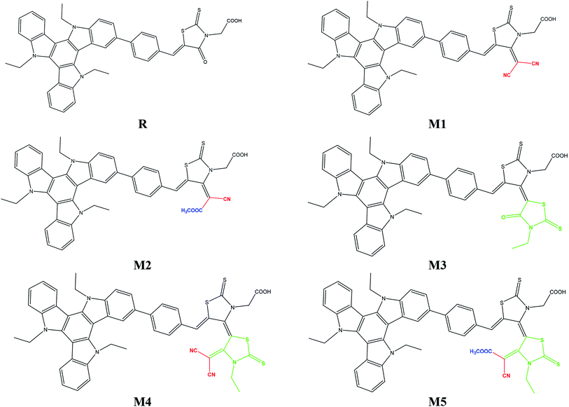
To address the increasing demand of efficient photovoltaic compounds for modern hi-tech applications, efforts have been made herein to design and explore triazatruxene-based novel donor materials with greater efficiencies. Five new molecules, namely M1–M5, were designed by structural modification of acceptor moiety (rhodanine-3-acetic acid) of well known experimentally synthesized JY05 dye (reference R), and their optoelectronic properties are evaluated to be used as donor molecules in organic solar cells. In these molecules M1–M5, triazatruxene acts as a donor unit and benzene spaced different end-capped moieties including 2-(4-(dicyanomethylene)-2-thioxothiazolidin-3-yl)acetic acid (A1), (E)-2-(4-(1-cyano-2-methoxy-2-oxoethylidene)-2-thioxothiazolidin-3-yl)acetic acid (A2), (Z)-2-(3′-ethyl-4′-oxo-2,2′-dithioxo-3′,4′-dihydro-2′H,5H-[4,5′-bithiazolylidene]-3(2H)-yl)acetic acid (A3), (Z)-2-(4′-(dicyano-methylene)-3′-ethyl-2,2′-dithioxo-3′,4′-dihydro-2′H,5H-[4,5′-bithiazol-ylidene]-3(2H)-yl)acetic acid (A4) and 2-((4Z,4′E)-4′-(1-cyano-2-methoxy-2-oxoethylidene)-3′-ethyl-2,2′-dithioxo-3′,4′-dihydro-2′H,5H-[4,5′-bithiazolylidene]-3(2H)-yl)acetic acid (A5) respectively, as acceptor units. The electronic, photophysical and photovoltaic properties of the designed molecules M1–M5 have been compared with reference molecule R. All designed molecules exhibit reduced energy gap in the region of 1.464–2.008 eV as compared to reference molecule (2.509 eV). Frontier molecular orbital (FMO) surfaces confirm the transfer of charge from donor to acceptor units. All designed molecules M1–M5 exhibited an absorption spectrum in the visible region and they were broader as compared to that of reference R. Especially, M5 with highest λmax value 649.26 nm and lowest transition energy value 1.90 eV was accredited to the strong electron withdrawing end-capped acceptor moiety A5. The highest value of open circuit voltage (Voc) 1.02 eV with respect to HOMOdonor–LUMOBTP-4Cl was shown by M5 among all investigated molecules which was 0.15 V larger than reference molecule R. The designed molecule M5 is proven to be the best candidate for both electron and hole transport mobilities due to its smallest λe (0.0212 eV) and λh (0.0062 eV) values among all studied molecules.
1. Introduction
In recent years, there has been a great interest in clean energy around the world due to a rapid increase in global development and environmental pollution. To meet the current demand of energy, the usage of fossil fuel reserves is at its peak. The most prospective method to solve the energy crisis is to convert solar energy into electrical energy. The promising approach of converting sunlight directly into electricity is achieved via the use of solar cells. Due to large advantages including high power conversion efficiency (PCE), non-toxicity, stability and abundance, silicon had been widely used in solar cells. But recently, owing to its non-tunable energy levels, brittleness and high cost, a drastic decrease in the use of silicon has been noticed. On the other hand, various advantages of organic solar cells such as tunable energy levels, light weight, easy processability and low cost have made them efficient alternative devices.1–5 Metal-free organic sensitizers have been largely explored recently for their environmentally friendly characteristics, low cost, facile synthesis, high molar extinction coefficient and their structural diversity.6 Mostly, the structure of organic sensitizers adopts the donor–π-bridge–acceptor (D–π–A) configuration which facilitates the intramolecular transfer of electron charge density from D to A units after passing through a π-bridge.7–9Polycyclic aromatic hydrocarbons (PAHs) are getting important considerations nowadays owing to their versatile optical and electronic properties and large number of applications in organic light emitting diodes (OLEDs),10 organic photovoltaics (OPVs)11 and organic field-effect transistors (OFETs).12 Among different PAHs, triazatruxene (5,10,15-triethyl-10,15-dihydro-5H-diindolo[3,2-a:30,2′-c]carbazole) abbreviated as TAT is a π-extended conjugated C3-symmetric planar structure with strong electron donating capability due to its electron-rich architecture.13–15 The TAT structure is a symmetric indole cycle-trimer with extended delocalized π-system in which three indole units form an overlapping framework combined by one benzene ring.16 Due to electron-rich structure and strong potential for intramolecular charge transfer (ICT), TAT presents immense probable applications in hole transporting materials with high hole mobility,16,17 fluorescent sensors,18 organic lasers,19 OFETs,12 liquid crystal displays (LCDs),20 OPVs,21 OLEDs,22 two-photon absorption (TPA)23 and nonlinear optics (NLO).24 The photo-electronic properties on the other hand are strongly influenced by electron acceptor units because injection of the electrons from dye molecule to semiconductor surface takes place through acceptor segments.25,26
Therefore, an electron-deficient acceptor segment is crucial to induce donor to acceptor charge transfer.27 In series of organic dyes, strong electron-withdrawing capable rhodanine-3-acetic acid has been used. For instance, rhodanine-3-acetic acid containing indoline-based dye D149 produced 9.03% PCE value.28 Similarly, by substituting n-octyl group onto the rhodanine ring of D149 dye gave PCE of 9.52% in another indoline dye D205.28 Thus, taking the clue from increase in PCE by substitution on the rhodanine ring, we come across a dye JY05 (ref. 29) containing TAT as donor unit and benzene spaced strong electron-withdrawing capable rhodanine-3-acetic acid, and designed five new molecules M1–M5 by substituting rhodanine ring with different end-capped acceptor moieties. The electronic, photophysical and photovoltaic properties of designed molecules M1–M5 were compared with reference dye JY05 (R) and highly effective donor materials with efficient acceptor moieties were recommended for their use in organic solar cells.
2. Computational procedure
The entire quantum chemical calculations in this study were performed with the help of Gaussian 09 program package.30 The Gauss View 5.0 (ref. 31) program was used for making input files and visualization of results. Initially, gas-phase geometry optimization without symmetry restrictions of reference compound (R) was made employing density functional theory (DFT) calculations at five exchange–correlation (XC) functionals B3LYP,32 CAM-B3LYP,33 MPW1PW91,34 ωB97XD,35 LC-BLYP36 and two basis sets 6-31G(d,p), 6-311G(d,p) combination. The selection of best available level of theory and basis set was made by simulating the absorption spectrum (λmax) of reference compound (R) employing time dependent density functional theory (TD-DFT) calculations at B3LYP, CAM-B3LYP, MPW1PW91, ωB97XD, LC-BLYP functionals and 6-31G(d,p), 6-311G(d,p) basis sets.37–44 The λmax of R obtained theoretically (in gas and solvent phase) was compared with the experimental data for validation of theoretical methods.37–44 A good agreement with experimental λmax value of R is shown by B3LYP/6-311G(d,p) level of theory. Therefore, this level of theory was selected for further calculations of designed molecules (M1–M5). The frequency analysis followed by the geometry optimization was executed for further confirmation of stability associated with the optimized geometries of R and M1–M5. The absence of negative eigen values among all calculated frequencies verified the optimized geometries at true minimum in potential energy surfaces. The UV-vis spectra of M1–M5 was calculated in THF solvent at TD-DFT/B3LYP/6-311G(d,p) level of theory using conductor-like polarizable continuum model (CPCM).45 The data obtained from Gaussian calculations was plotted by using Origin 8.0 program. The DFT/B3LYP/6-311G(d,p) level of theory was used for calculations of frontier molecular orbital (FMO) analysis, charge transfer, density of state, cation, anion and neutral molecule calculations of R and M1–M5. Density of state (DOS) which supports the distribution of electron density is calculated by using PyMOlyze 2.0 program.46 The reorganization energy calculations of R and M1–M5 were also computed by using B3LYP/6-311G (d,p) level of theory. The external reorganization energy (λext) and internal reorganization energy (λint) are the two major parts of reorganization energy. The external environmental relaxation and effect of polarization on external surrounding medium are explained by λext. On the other hand, quick changes in the internal structure are enlightened with the assistance of λint. In our study, external environmental effect is neglected and only internal reorganization energy is discussed. Hence, reorganization energy of the hole (λh) and electron (λe) are calculated with the assistance of following eqn (1) and (2).| λe = [E−0 − E−] + [E0− − E0] | (1) |
| λh = [E+0 − E+] + [E0+ − E0] | (2) |
3. Results and discussion
The focus of present probe was to theoretically design novel triazatruxene-based donor materials with promising acceptor units and predict their optoelectronic properties. For systematic designing, triazatruxene-based experimentally synthesized D–π–A metal free organic dye JY05 (named as reference R in this study) was used.29 The reference R structure is composed of three blocks: triazatruxene as donor (D) unit, benzene ring as π-conjugated bridge and rhodanine-3-acetic acid (RAA) as acceptor (A) moiety. The screening of pendant acceptor group is an important factor and plays a key role in D–π–A configurations for achieving fine photovoltaic properties. Therefore, with a motivation to develop novel materials with excellent photovoltaic properties, structural tailoring of R was made by considering it prototype and keeping the donor, π-bridge part fixed and replacing the end-capped moiety (RAA) with different acceptor blocks.Five new molecules namely; M1, M2, M3, M4 and M5 were designed by decorating the acceptor moiety (RAA) of R with 2-(4-(dicyano-methylene)-2-thioxothiazolidin-3-yl)acetic acid (A1), (E)-2-(4-(1-cyano-2-methoxy-2-oxoethylidene)-2-thioxothiazolidin-3-yl)acetic acid (A2), (Z)-2-(3′-ethyl-4′-oxo-2,2′-dithioxo-3′,4′-dihydro-2′H,5H-[4,5′-bithiazolylidene]-3(2H)-yl)acetic acid (A3), (Z)-2-(4′-(dicyano-methylene)-3′-ethyl-2,2′-dithioxo-3′,4′-dihydro-2′H,5H-[4,5′-bithiazolylidene]-3(2H)-yl)acetic acid (A4) and 2-((4Z,4′E)-4′-(1-cyano-2-methoxy-2-oxoethylidene)-3′-ethyl-2,2′-dithioxo-3′,4′-dihydro-2′H,5H-[4,5′-bithiazolylidene]-3(2H)-yl)acetic acid (A5) respectively. The structures of M1–M5 are portrayed in Fig. 1.
For the estimation of optoelectronic properties of R, five DFT based functionals including B3LYP, CAM-B3LYP, MPW1PW91, ωB97XD, LC-BLYP and two basis sets 6-31G(d,p), 6-311G(d,p) combination were used.
The λmax values of R in gas phase with B3LYP, CAM-B3LYP, MPW1PW91, ωB97XD and LC-BLYP functionals are found to be 374 nm, 356 nm, 395 nm, 345 nm, 306 nm with 6-31G(d,p) basis set and 376 nm, 361 nm, 397 nm, 350 nm, 312 nm with 6-31G(d,p) basis set respectively. On the other hand in solvent (THF) phase, λmax values of R are computed to be 442 nm, 369.75 nm, 412 nm, 359 nm, 317 nm and 443 nm, 374 nm, 413 nm, 363 nm, 323 nm with 6-31G(d,p) and 6-311G(d,p) basis sets in conjunction with B3LYP, CAM-B3LYP, MPW1PW91, ωB97XD and LC-BLYP functionals respectively. The reported value of R (456 nm) is compared with DFT findings simulated in bar chart and displayed in Fig. 2. It is evident from Fig. 2 that B3LYP/6-311G(d,p) level calculations in THF are found in good agreement with experimental findings as compared to other functionals. Thus, B3LYP/6-311G(d,p) functional is opted for auxiliary computations of reference R and designed molecules (M1–M5). The optimized geometries of designed molecules M1–M5 calculated at B3LYP/6-311G(d,p) level of theory are shown Fig. 3. The DFT and TD-DFT computations were performed on R and M1–M5 to describe how end-capped acceptor group modifications affects the optical, photophysical and photovoltaic properties of the organic sensitizers.
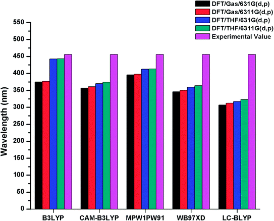 | ||
| Fig. 2 Simulated bar chart for reference R (in gas and solvent THF) with B3LYP, CAMB3LYP, MPW1PW91, ωB97XD, LC-BLYP functionals and 6-31G(d,p), 6-311G(d,p) basis sets. | ||
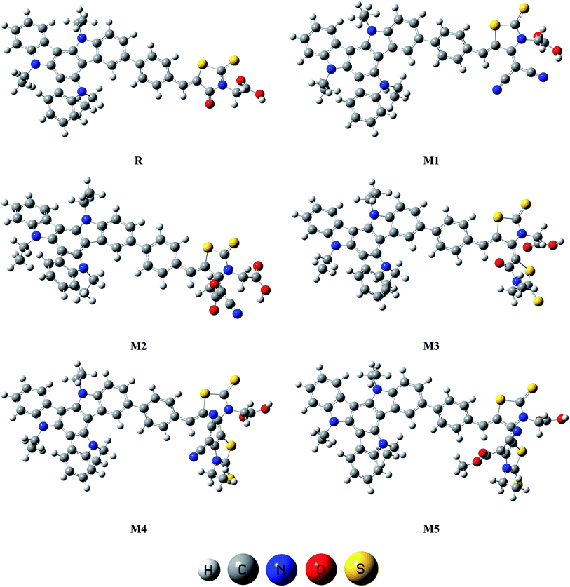 | ||
| Fig. 3 Optimized molecular geometries of reference R and designed molecules (M1–M5) at B3LYP/6-311G(d,p) level of theory. | ||
3.1 Frontier molecular orbital diagram
It is known that charge transition character of dyes is strongly influenced by the distribution of frontier molecular orbitals (FMOs) of sensitizers. In terms of band theory, HOMO refers as valence band, while LUMO corresponds to the conduction band. The FMOs energy gap (Egap = ELUMO − EHOMO) is a representative signature found on photovoltaic materials.48–53 PCE of solar cells are intimately associated to FMOs energies and their energy band gaps. The Egap predicts the driving force for exciton dissociation and open circuit voltage (Voc). It also characterize the electron transport properties, dynamic stability, chemical hardness, chemical reactivity and softness of the molecules.54 In DSSCs, organic dye act as a photo-sensitizer and its major role is to sensitize the photoelectrode with large band gaps. After adsorption of the dye on photoelectrode surface, excited electron upon illumination is injected into the photoelectrode surface. For better optical transitions which lead to photo-induced electron transfer from dye to the semiconductor, dye sensitizers HOMO–LUMOs location and their energy level must need to match the conduction band edge (CBE) level of the semiconductor and iodine/iodide redox potential. Thus analysis for distribution of charges on FMOs particularly the charge-separated between virtual and occupied orbitals is important to understand the optical properties and electronic behaviour of the investigated compounds during the excitation process.Assuming all these considerations, FMOs analysis have been performed on R and M1–M5 molecules at B3LYP/6-311G(d,p) level of theory. The results of FMOs investigation including HOMO energy (EHOMO), LUMO energy (ELUMO) and Egap values are tabulated in Table 1. The FMOs contour surfaces illustrating the density distribution pattern of electrons and charge transfer in HOMO and LUMO are displayed in Fig. 4.
| Molecules | HOMO (EHOMO) | LUMO (ELUMO) | Egap = ELUMO − EHOMO |
|---|---|---|---|
| R | −5.299 | −2.790 | 2.509 |
| M1 | −5.398 | −3.563 | 1.835 |
| M2 | −5.418 | −3.452 | 1.966 |
| M3 | −5.320 | −3.312 | 2.008 |
| M4 | −5.422 | −3.925 | 1.497 |
| M5 | −5.444 | −3.980 | 1.464 |
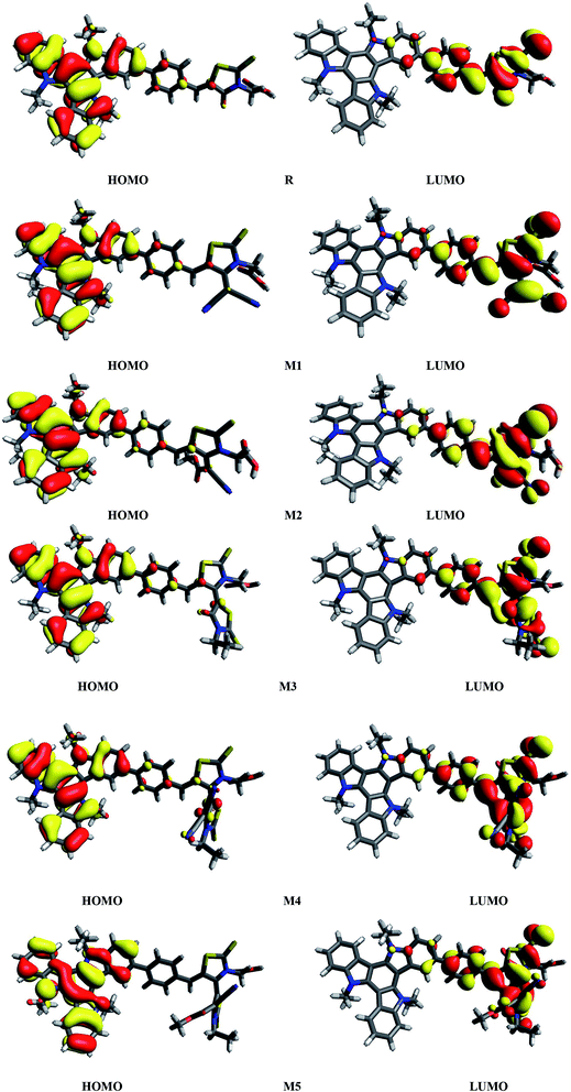 | ||
| Fig. 4 HOMOs and LUMOs of reference R and designed molecules (M1–M5) at B3LYP/6311G(d,p) level of theory. | ||
Table 1 indicates that EHOMO and ELUMO values of R are found to be −5.299 eV and −2.790 eV respectively which lead to narrow Egap value of 2.509 eV. The EHOMO of M1, M2, M3, M4 and M5 are computed as −5.398, −5.418, −5.320, −5.422 and −5.444 eV respectively. On the other hand, the values −3.563, −3.452, −3.312, −3.925 and −3.980 are assigned to the ELUMO values of M1, M2, M3, M4 and M5 respectively. Overall among all investigated molecules (R and M1–M5), the lowest values of EHOMO and ELUMO are shown by M5 indicating the highest stabilized HOMO and LUMO in M5 due to the extended conjugation of strong electron withdrawing end-capped moiety A5. The highest value of HOMO and LUMO is noted in R. The HOMO and LUMO values of M1 are found to be lower than HOMO and LUMO values of R and M3 respectively, indicating the better withdrawing effect of dicyano groups present in end-capped acceptor A1. On the other hand, HOMO, LUMO values in case of M1 is observed larger than M4, M5 corresponding values proving the better efficiency of M4 and M5 due to extra rhodanine ring equipped with dicyano group in end-capped acceptor A4 and combination of one cyano and ester group in end-capped acceptor A5 respectively. In case of M2, the HOMO and LUMO levels are found more stabilized than R and M3 corresponding energy levels which indicate the less significant efficiency of acceptor moieties RAA in R and two rhodanine rings in M3 as compared to end-capped acceptor A2 of M2. Similarly, HOMO and LUMO values of M2 are found larger than M4, M5 values indicating that end-capped acceptor moieties A4 and A5 in M4 and M5 respectively withdrawing the charge efficiently due to extended conjugation and presence of strong pulling cyano and ester groups. The HOMO value of M3 is computed close to R molecule due to absence of extra cyano and ester groups in end-capped acceptor A3 unit, while LUMO energy level is found more stabilized than R which results in narrow Egap value than R. The case of M4 is similar to M5 which contain the most stabilized HOMO and LUMO energy level values than R, M1, M2 and M3's HOMO, LUMO values. Overall, HOMO and LUMO values of all investigated molecules are found to be in following decreasing order: R > M3 > M1 > M2 > M4 > M5 and R > M3 > M2 > M1 > M4 > M5 respectively.
Another important tool to describe the charge transfer is the Egap value. The highest Egap value (2.509 eV) among all investigated compounds (R and M1–M5) is found to be in R due to reduced electron withdrawing effect of RAA acceptor as compared to end-capped acceptors A1, A2, A3, A4 and A5. It can be seen from Table 1 that Egap value in designed compounds (M1–M5) are diminished as compared to R. This proves that designed compounds M1–M5 will show efficient optoelectronic properties as compared to R molecule. The Egap values of investigated compounds are found in the range of 1.464–2.509 eV. In M1, reduction (of 0.674 eV) in energy gap value than R is noticed with Egap value of 1.835 eV due to strong pulling nature of dicyano groups present in end-capped acceptor A1 unit as compared to R. The Egap value of M1 is computed smaller than R, M2, M3 implying the better efficiency of A1 acceptor moiety than A2, A3 containing one cyano, one ester group and two rhodanine rings respectively. The Egap value of M2 is observed narrower than R, M3 due to extended conjugation and presence of one cyano, one ester group in A2 acceptor. However, M2 energy gap is found wider than M1, M4 and M5 due to less pulling nature and electron withdrawing characteristic of end-capped acceptor moiety A2 as compared to A1, A4 and A5 acceptors respectively. Similar the HOMO, LUMO values of M3, Egap values are also found smaller than only R and larger than M1, M2, M4, M5 indicating the efficiency of end-capped acceptor A3 only better than R acceptor moiety RAA. In M4, Egap becomes more abridged to 1.497 eV which is smaller with respect to R, M1, M2, M3 and greater than M5 Egap value only. The lowest energy gap value is marked in M5 with 1.464 eV value (1.045 eV smaller than R) owing to strong electron withdrawing capability combined with extended conjugation present in end-capped acceptor A5 with respect to other acceptor moieties RAA, A1, A2, A3, A4. Overall, energy gap values of investigated molecules are marked in the following decreasing order: R > M3 > M2 > M1 > M4 > M5 which is in accordance with the decreasing order of LUMO values. Preceding discussion also evident that power of end-capped acceptor moieties are in inverse relation with the band gap value and increased in the following order RAA < A3 < A2 < A1 < A4 < A5.
Furthermore, partial density of states (PDOS) analysis of R and M1–M5 molecules has been performed at B3LYP/6-311G(d,p) level of theory to support the FMOs diagram (Fig. 4). For in Fig. 5 is supported the facts described in FMO diagram.
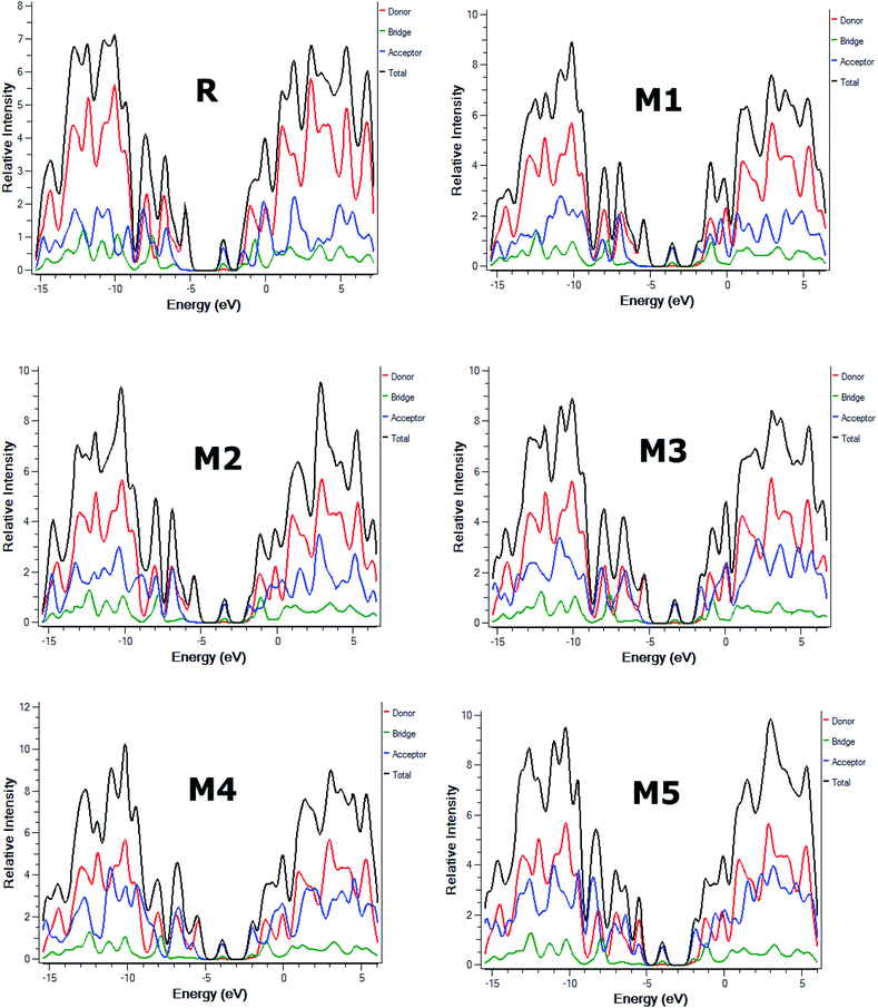 | ||
| Fig. 5 The DOS around the HOMOs and LUMO of reference R and the designed molecules M1–M5 at B3LYP/6-311G(d,p) level of theory. | ||
It can be seen from Fig. 4 and evident from Fig. 5 that distribution pattern of electron density is altered around LUMO and HOMO due to strong pulling and electron withdrawing effect of end-capped acceptor moieties. In R, the HOMO is populated mainly on donor part and LUMO on the other hand is concentrated equally on acceptor unit and on neighbouring bridge. Similar effect is observed in designed molecule M1, where HOMO is located mainly on donor segment and LUMO density is seen uniformly on acceptor A1-bridge part. In case of M2, M3 and M4, the HOMO charge density is spread on donor unit and minute charge is seen on bridge part, while LUMO is distributed primarily on benzene ring (bridge) and end-capped acceptor units A2, A3 and A4. The case of M5 is bit different from all other molecules containing HOMO charge density only on donor unit, LUMO part is mainly populated over pendant acceptor A5 and partially on bridge part. On the whole, these density distribution patterns indicate that delocalization of electrons is occurred and healthy amount of charge is transferred in all designed molecules M1, M2, M3, M4 and M5 from donor segment to acceptor unit with the assistance of bridge part.
4. Optical properties
In order to assess the photophysical properties of reference R29 and designed molecules M1–M5, UV/vis absorption spectra in THF solvent has been computed employing TD-DFT at B3LYP/6-311G(d,p) level of theory. The results obtained from spectral analysis including maximum absorption wavelengths (λmax), oscillator strengths (fos), transition energy (Ex), transition natures of compounds and dipole moment values are summarized in Table 2.| Molecules | Calculated λmax (nm) | Expected λmax (nm) | Ex (eV) | fos | Major MO assignments | Dipole moment (D) |
|---|---|---|---|---|---|---|
| a H = HOMO, L = LUMO, H−1 = HOMO−1, H−2 = HOMO−2, etc. | ||||||
| R | 443.22 | 456 (ref. 29) | 2.79 | 0.81 | H−2 → L (97%) | 6.962 |
| M1 | 550.69 | 2.25 | 0.64 | H−2 → L (99%) | 9.312 | |
| M2 | 541.97 | 2.28 | 0.69 | H−2 → L (98%) | 12.003 | |
| M3 | 577.01 | 2.14 | 0.68 | H−2 → L (98%) | 7.262 | |
| M4 | 619.66 | 2.00 | 0.29 | H−3 → L (96%) | 7.976 | |
| M5 | 649.26 | 1.90 | 0.42 | H−3 → L (94%) | 11.192 | |
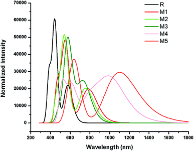
The simulated absorption spectrum of all investigated molecules (R and M1–M5) are shown in Fig. 6 which exhibit two absorption peaks of each investigated molecule namely main and secondary absorption peak respectively.
The results mentioned in Table 2 indicate that maximum absorption peak of reference R is observed at 443.22 nm which are comparable to their corresponding experimental absorption maximum value 456 nm. We can clearly see from the results that λmax values are strongly affected by electron withdrawing end-capped acceptor moieties which caused the red shift in absorption spectra.41 Results also indicate that all investigated molecules (reference R and designed M1–M5) exhibit absorbance in the visible region. The absorption band of designed molecules M1–M5 covers the range from 541.97 nm to 649.26 nm. Overall, maximum absorption values of designed M1–M5 molecules are observed greater in magnitude and red shifted than λmax value of reference R (Table 2 and Fig. 6).
The reference R molecule is found to have the lowest λmax value among all studied molecules. The maximum absorption peaks of M1–M5 are computed at 550.69 nm, 541.97 nm, 577.01 nm, 619.66 nm and 649.26 nm respectively. The introduction of strong electron withdrawing dicyano acceptor group A1 in M1 molecule successfully increased (red shift) the absorption maximum value to 550.69 nm which confirmed the effectiveness of A1 acceptor as compared to RAA acceptor moiety in R molecule. The λmax value of M2 (541.97 nm) is observed bit smaller than λmax value of M1 but found red shifted as compared to reference R which proved that end-capped acceptor A2 containing one cyano and one ester group efficiency is greater than RAA of R but less than A1 acceptor efficiency. Replacement of RAA of R with two rhodanine rings (acceptor A3) in M3 further enhanced the λmax value to 577.01 nm. The introduction of strong electron withdrawing dicyano group on second rhodanine ring in end-capped A4 acceptor further improved the maximum absorption wavelength to 619.66 nm in M4. The enhancement of λmax value in M4 confirmed the better efficiency of end-capped moiety A4 as compared to A1, A2 and A3 units. Among all studied compounds, the highest λmax value (649.26 nm) and red shift is found in M5 due to extended conjugation combined with strong pulling character of A5 acceptor motif. The best efficiency of end-capped acceptor A5 in maximum red shifting the λmax value is in accordance with the large lowering of energy gap findings as discussed above. Overall, designed molecules M1, M2, M3, M4 and M5 exhibit red shift of 107.46 nm, 98.75 nm, 133.79 nm, 176.44 nm and 206.03 nm as compared to reference R molecule respectively. The λmax values of reference R and designed M1–M5 molecules are found in the following increasing order: R < M2 < M1 < M3 < M4 < M5.
Another important factor that offers useful insights into the charge transfer character is transition or excitation energy of investigated molecules. Literature suggests that molecules holding lower transition energy values contain higher charge transport ability, easy excitation between HOMO to LUMO, hence, high power conversion efficiency. The highest excitation energy is marked with 2.79 eV value in reference compound R. The introduction of strong electron withdrawing end-capped acceptor units lowers the excitation energy values in designed molecules M1–M5. Therefore, computed transition energy values of designed molecules M1–M5 are found less than reference molecule R. The excitation energy value of M1, M2, M3 and M4 are found to be 2.25, 2.28, 2.14 and 2.00 eV respectively. The lowest excitation energy value 1.90 eV is found in M5 due to combined effect of extended conjugation and strong electron withdrawing end-capped acceptor A5. The decreasing order of excitation energy values of all investigated compounds are found exactly in accordance with the increasing λmax order: R > M2 > M1 > M3 > M4 > M5. In a nut shell, M5 contain the lowest transition energy, least energy gap and highest λmax value which is considered as an ideal condition of a material for utilization of its optoelectronic properties in solar cell applications.
The preceding discussion concludes that all designed molecules M1–M5 contain lower transition energy and higher λmax value which lead to better optoelectronic properties than reference R molecule. Therefore, all designed molecules particularly M5 may have the potential to use as a donor material in solar cell applications.
5. Reorganization energy
Another tool to evaluate the performance of organic solar cells is reorganization energy (electron and hole). The reorganization energy is linked with the charge mobilities. Reorganization energy and charge mobilities are in an inverse relationship; the lower the reorganization energy, the higher the charge mobilities. It depends on many factors, but is mainly influenced by the geometry of the cations and anions according to eqn (1) and (2). The anionic geometry indicates the electron transfer from the donor material, while the cationic geometry shows the hole in acceptor material. The overall reorganization can be used to calculate the charger transfer between the donor and acceptor unit. Reorganization is classified into two parts; internal reorganization energy (λint) and external reorganization energy (λext). The external reorganization deals with the polarization effect on the external environment while the internal reorganization provides information on quick changes in the internal geometry. Here, we neglect the external environmental effects in our study and discuss only the internal reorganization energy.39 The energy cost for change of geometry from neutral to charge or from charge to neutral specie can be estimated from intra molecular reorganization energy employing Marcus equation.55
 | (3) |
The λi in term of reorganization energy can be explained from above relation which indicates that electron transfer rate (kET) will be higher if smaller will be the geometry relaxation. If similarity exists between geometry of the neutral (final) and ionized (initial) states, then transfer of electron may take place without waiting for the occurring of vibrations. On the other hand, lacking of similarity between geometries require wait for vibrations to occur which orient the acceptor unit into an orientation analogous to donor part, hence, transfer of electrons may take place. The transfer of electrons is an activated process which entails vibrations that will set up the system for movement of electrons. To count the reorganization energy value of investigated molecules (R and M1–M5), calculations have been performed at B3LYP/6-311G(d,p) level of theory and results for the reorganization energy values of electron and hole are collected in Table 3.
Results mentioned in Table 3 indicate that designed molecules contain excellent hole (λh) and electron (λe) mobilities. The reference molecule R is found to have λe value of 0.0223 eV. As compared to reference compound R, the designed molecules M1, M3 and M4 are found to be with greater λe value of 0.0236, 0.0246 and 0.0253 eV respectively. On the other hand, M2 and M5 exhibit relatively small λe values 0.0218 eV and 0.0212 eV respectively which denotes the high electron mobility in these compounds as compared to reference R molecule. The smallest λe value among all investigated molecules is marked in designed molecule M5 which implies the best mobility of electrons among donor and acceptor units. The λe values of all investigated molecules are found to be in following decreasing order: M4 > M3 > M1 > M4 > R > M2 > M5.
A comparison between reorganization energy of hole (λh) values for all investigated molecules (R and M1–M5) are made in Table 3. The λh value of reference molecule R is observed as 0.0086 eV. The designed molecules M1 and M2 shows bit larger λh values 0.0124 eV and 0.0127 eV respectively as compared to R. The remaining designed molecules M3, M4 and M5 are noted with small λh value of 0.0069 eV, 0.0066 eV and 0.0062 eV as compared to reference molecule R respectively. Compound M5 is found to be the best for hole transport mobility due to its lowest λh value 0.0062 eV among all investigated compounds (R and M1–M5). The λh values of all investigated molecules are found to be in following decreasing order: M2 > M1 > R > M3 > M4 > M5.
It is well evident from above discussion that designed molecules are fine candidates for electron and hole mobilities. On the whole, the reorganization energy values of hole (λh) are found smaller as compared to reorganization energy values of electron (λe) for all investigated molecules (R and M1–M5) which points out that the designed molecules are best for hole charge carrier. Furthermore, designed molecule M5 is proven to be best candidate for both electron and hole transport mobilities due to its smallest λe and λh values.
6. Open circuit voltage
Another important factor used to describe the performance of organic solar cells is open circuit voltage (Voc).56 It tells the maximum amount of current which can be drawn from any optical device.47 The Voc is actually the zero current at maximum voltage that can be obtained from any device. Different factors on which Voc relies are; external fluorescence efficiency, charge-carrier recombination, work functions of the electrodes, light source, temperature of solar cell device, light intensity, environmental factors, types and energy levels of materials. Mainly, Voc depends on both light generated and saturation current that help the recombination in devices. The difference between donor and acceptor molecules corresponding HOMO and LUMO energies is approximately proportional to Voc. To achieve higher Voc, HOMO level of donor molecule should be low enough while acceptor molecular LUMO level should be with higher value.57In present quantum chemical exploration, Voc results for R and M1–M5 are computed using two famous acceptor molecules. Firstly, the HOMO energy levels of our investigated reference R and designed donor molecules M1–M3 are compared with LUMO energy level of renowned acceptor polymeric material PC61BM (see Fig. 7). Secondly, recently reported acceptor molecule (BTP-4Cl) with record breaking efficiency of over 16% and increased Voc values58 are used to compare the Voc results of our investigated compounds R and M1–M5 (see Fig. 8). The Voc of PC61BM is changeable and relies entirely on the donor materials that combine with it. For example, Voc of PC61BM with well-known donor materials PBDB-T, PTB7-Th and P3HT are found to be 0.78 eV,59 0.75 eV,60 and 0.66 eV (ref. 61) respectively. The HOMO and LUMO levels of recently reported BTP-4Cl molecule are −5.68 eV and −4.12 eV respectively.58
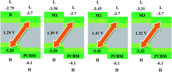 | ||
| Fig. 7 The value of open circuit voltage (Voc) of reference R and designed molecules M1–M3 with respect to the acceptor moiety PC61BM. | ||
 | ||
| Fig. 8 The value of open circuit voltage (Voc) of reference R and designed molecules M1–M5 with respect to the acceptor moiety BTP-4Cl. | ||
The theoretical values of open-circuit voltage (Voc) of the solar cells have been calculated from the equation proposed by Scharber and his co-workers62 expressed as follows:
| Voc = (|EDHOMO| − |EALUMO|) − 0.3 | (4) |
The calculated results are displayed in Fig. 7 and 8. The Voc value of reference molecule R with respect to HOMOdonor–LUMOPC61BM energy gap is found to be 1.29 V. It is quite fascinating that designed molecules M1, M2 and M3 with respect to LUMOPC61BM energy gap reveal higher open circuit voltage values of 1.39 V, 1.41 V and 1.32 V respectively as compared to reference molecule R. The reason for higher Voc value of designed molecules than reference R molecule is due to the lower HOMO level of M1–M3 as compared to HOMO level of R. The HOMO level of donor molecules are observed in following decreasing order: R > M3 > M1 > M2. The Voc value of M1 (1.39 V) is noticed 0.10 V greater than the reference R.
Similarly, M2 Voc value is computed 0.12 V greater than the R and 0.2 V greater than M1 molecule. In case of M3, Voc value is found 0.3 V greater than reference R but less than designed molecules M1 and M2.
Similarly, eqn (4) is utilized to calculate the Voc values of R and M1–M5 with respect to the LUMOBTP-4Cl. The Voc value of R is found to be 0.87 V which is the least one among all investigated compounds. An increase of 0.10 V from the R molecule is observed in M1 with Voc value of 0.97 V. Similarly M2 is found to be with Voc value of 0.99 V which is 0.12 V and 0.2 V greater than the R and M1 molecules respectively. The Voc value of M3 is computed as 0.90 V, which is 0.3 V larger than reference R but less than M1 and M2. The M4 molecule took the second place in terms of highest Voc value marked as 0.13 V larger than reference molecule R. The highest value of open circuit voltage 1.02 V among all investigated molecules is measured in designed molecule M5 which is 0.15 V larger than reference molecule R. Overall, open circuit voltage of investigated molecules (R and M1–M5) with respect to HOMOdonor–LUMOBTP-4Cl energy gap is noticed in accordance with the reverse HOMO energy level order as: M5 > M4 > M2 > M1 > M3 > R.
It can be seen that that Voc values of R, M1, M2 and M3 are found to be with similar order (M2 > M1 > M3 > R) and with similar difference (of 0.10 V, 0.12 V and 0.3 V) when compared with both PC61BM and BTP-4Cl acceptors results.
It is well evident from above discussion that designed donor molecules M1–M3 (except M4 and M5) are suitable candidates when combined with PC61BM polymer acceptor. On the other hand, all designed molecules M1–M5 when compared with recently reported molecule BTP-4Cl containing record breaking efficiency exhibit appropriate open circuit voltage values greater than the reference molecule R, hence are suitable potential donor materials for enhancement of optoelectronic properties. The compound M5 particularly exhibit lowest HOMO and highest open circuit voltage values and can be considered as potential donor candidate in solar cell. Since, HOMO and LUMO energy gap is an important tool to enhance the power conversion efficiency of solar cell by transition of electrons from donor to acceptor segments. Therefore, molecular orbital diagrams of R, M1–M3 and R, M1–M5 with respect to PC61BM polymeric acceptor and recently reported BTP-4Cl molecule are drawn in Fig. 9 and 10 respectively.
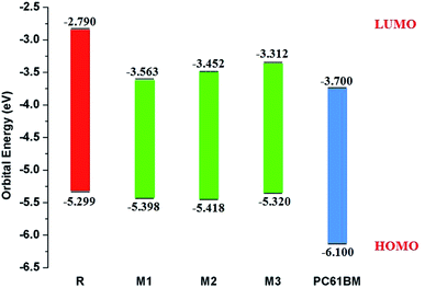 | ||
| Fig. 9 Molecular orbital diagram of reference R and designed molecules M1–M3 donors with PC61BM acceptor. | ||
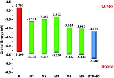 | ||
| Fig. 10 Molecular orbital diagram of reference R and designed molecules M1–M5 donors with BTP-4Cl acceptor. | ||
7. Charge transfer analysis
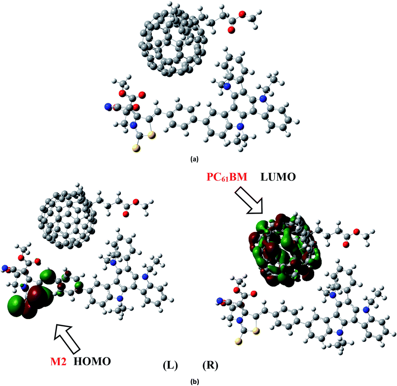
To analyze the charge transfer characteristic of investigated molecules, the designed molecule M2 and M5 with reasonable electron and hole mobility due to low electron and hole reorganization energy values respectively have been selected among all studied molecules. For charge transfer analysis, complex of M2 molecule is formed with renowned acceptor polymeric material PC61BM. Similarly, complex formed between donor M5 and recently reported acceptor molecule (BTP-4Cl) with record breaking efficiency is also used to examine the transfer of charge.The interaction between M2 donor and PC61BM acceptor takes place in such a pattern that overall orientation of acceptor PC61BM becomes parallel to M2 molecule in which functional group side of PC61BM orients toward donor part of M2, while ball side of PC61BM point out toward acceptor A2 side of M2 molecule (Fig. 11a).
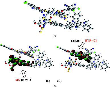
The electronic structure of the M2:PC61BM complex is significantly affected by the relative orientation of M2 and PC61BM which facilitate the transfer of charge among donor and acceptor segments. Similarly, the relative orientation of the complex formed between M5 and BTP-4Cl indicates that M5 wraps around BTP-4Cl to large extent. The central core of BTP-4Cl is observed close to the central part of the M5 molecule during wrapping orientation (Fig. 12a).
The dipole moment of both complexes are calculated because the presence of dipole from M2 and M5 to the acceptor has been suggested as the reasons for efficient exciton dissociation at the M2/PC61BM and M5/BTP-4Cl interfaces.63–66 The dipole moment in both M2:PC61BM and M5:BTP-4Cl systems are due to the electrostatic interactions of permanent electric moment of M2 and M5 with that of PC61BM and BTP-4Cl respectively. The literature suggests that polymer side mainly governed the dipole moment in such complexes. The direction of dipole in our study is found to be in line with this statement. In both studied complexes M2:PC61BM and M5:BTP-4Cl, the origination of dipole moment vector takes place from polymer acceptor face and directs in the direction of pendant donor part of designed molecules M2 and M5 respectively. The M2:PC61BM and M5:BTP-4Cl complexes are initially optimized at B3LYP/6-311G(d,p) level of theory and FMO analysis has been performed using same functional to evaluate the electronic structure and spatial distribution pattern of HOMO–LUMO around the complexes. The optimized geometries and results for HOMO and LUMO of M2:PC61BM and M5:BTP-4Cl complexes have been shown in Fig. 11 and 12 respectively. It can be seen from Fig. 11 that HOMO charge density in M2:PC61BM complex is populated on A2 acceptor part of the donor M2 molecule (Fig. 11b (L)). On the other hand, LUMO charge density is distributed on polymer acceptor PC61BM (Fig. 11b (R)). Similar and favourable charge transfer is observed in case of M5:BTP-4Cl complex in which HOMO is populated on the acceptor A5 part of the M5 donor molecule. While, LUMO is concentrated on the central core of the polymer acceptor BTP-4Cl which indicate the successful transfer of charge from HOMO (donor) to LUMO (acceptor). Overall, orbital analysis clearly depicts that HOMO to LUMO excitation is actually transfer of charge from donor designed molecules M2 and M5 to polymer acceptors PC61BM and BTP-4Cl respectively.
Such type of transitions involving shifting of charge density from donor to acceptor segments transitions reflects the superposition of orbitals between the molecules which is a concrete evidence of charge transfer between different moieties.
8. Transition density matrix (TDMs) and exciton binding energy (Eb)
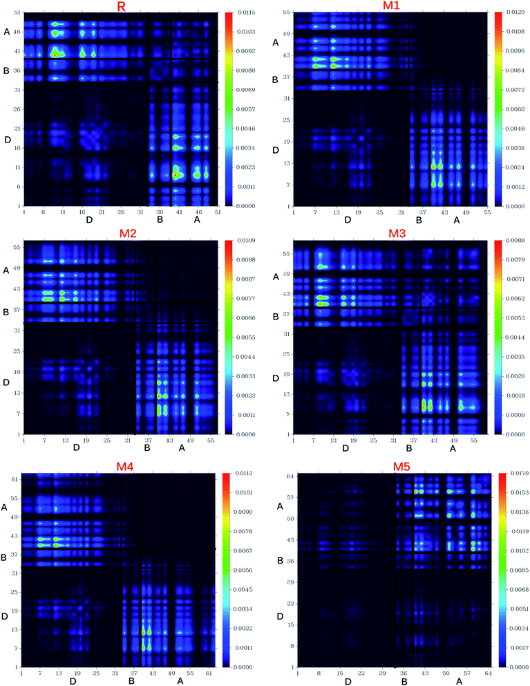
The nature of transitions in reference molecule R and designed molecules M1–M5 was estimated by computing the transition density matrixes (TDMs). The TDMs for emission and absorption of the S1 state are computed in vacuum using B3LYP method and 6-311G (d,p) basis set combination and results are displayed in Fig. 13. Due to small contribution of hydrogen atoms in transitions, the effect of hydrogen atoms has been ignored by default in present study. TDMs method is a key point which enables us to estimate the (i) electron hole localization; (ii) electronic excitation and (iii) excited state interaction among acceptor and donor units.67 To study these effects, we divided our reference R and designed molecules M1–M5 into three segments namely; donor (D), π-bridge (B) and acceptor (A).The TDMs diagrams indicate that reference R and M3 molecules exhibit similar behaviour in which electron coherence is partially available on the diagonal of donor, more on the bridge segment and mostly present on the end-capped acceptor moieties. The electron coherence in M1, M2 and M4 display similar trend and minutely available on donor part (non diagonal), more on the bridge segment and mainly present on the end-capped acceptors. The TDMs diagram of M5 confirms that electron coherence is not seen on the donor part, bridge unit contain partial electron coherence and main electron coherence is present only on end-capped acceptor moiety. The behaviour of electron coherence in reference R and designed molecules M1–M5 confirm that electron are successfully migrated from donor part to bridge unit which act as a facilitator for transfer of electron from donor to acceptor segments without trapping them and finally the electron charge density is reached to acceptor segments.
Furthermore, the decreasing order for coefficient of interaction connecting acceptor and donor segments is; R > M3 > M1 > M2 > M4 > M5. This sequence implies that the coupling of the hole and the electron of M5 may be lower with respect to the other investigated molecules, but it could show higher and easier exciton dissociation in the excited state.
The binding energy results indicate that the designed molecule M5 contain the biggest amount of charges which may be dissociated into separate charge easily. This result describes the highest charge dissociation efficiency of M5 molecule among all studied molecules (R and M1–M5). Furthermore, the charge dissociation ability of designed molecules M1–M5 is also found higher than R which implies that designed molecule M1–M5 would largely increase the overall current charge density Jsc as compared to reference molecule R. Overall, Jsc value will be largely increased by M5 molecule due to its highest charge dissociation efficiency among all investigated molecules.
Another promising factor that helps to evaluate the exciton dissociation potential, optoelectronic properties and performance of organic solar cells is the binding energy (Eb). The interaction of the coulombic forces among hole and electron is also estimated with the assistance of binding energy. A direct relation exists between binding energy and coulombic interaction between hole and electron which both in turn is inversely proportional to the exciton dissociation in excited state.
This implies that, higher Eb value results in higher coulombic interaction between hole and electron, hence, lower exciton dissociation will produced in excited state. The binding energy (Eb) values of reference R and designed molecules M1–M5 are calculated using following eqn (5).
| Eb = EH–L − Eopt | (5) |
| Molecules | EH–L (eV) | Eopt (eV) | Eb (eV) |
|---|---|---|---|
| R | 2.509 | 2.15 | 0.359 |
| M1 | 1.835 | 1.578 | 0.257 |
| M2 | 1.966 | 1.636 | 0.330 |
| M3 | 2.008 | 1.691 | 0.317 |
| M4 | 1.497 | 1.219 | 0.278 |
| M5 | 1.464 | 1.210 | 0.254 |
The Eb value of reference R molecule is found to be 0.359 eV. It is quite fascinating that binding energy of designed molecules M1–M5 is measured lower as compared to reference R molecule. The Eb values of M1, M2, M3, M4 and M5 are found to be 0.257, 0.330, 0.317, 0.278 and 0.254 eV respectively. The decreasing order for binding energies of reference and designed molecules is R > M2 > M3 > M4 > M1 > M5. These results with highest Eb value of reference R and lowest Eb value of M5 are in good agreement with transition density matrix results.
9. Conclusion
In summary, we have rational designed five novel triazatruxene-based D–π–A metal-free organic donor materials (M1–M5) from experimentally synthesized dye (R) using screening of different acceptor moieties. Quantum chemical calculations have been applied to explore the electronic structures, absorption spectra and photovoltaic properties of M1–M5 for use as donor molecules in organic solar cells. Overall due to better electron withdrawing end-capped acceptor moieties, the optoelectronic properties of designed molecules (M1–M5) found better than R. All designed molecules (M1–M5) exhibit reduced energy gaps in the range of 1.464–2.008 eV as compared to reference molecule (2.509 eV). Particularly, M5 displayed the lowest energy gap of 1.464 eV value (1.045 eV smaller than R) owing to strong electron withdrawing capability combined with extended conjugation present in end-capped acceptor moiety A5. All designed molecules M1–M5 showed absorption spectrum in visible region and broader in the span of 550–649 nm as compared to reference R (443 nm), especially M5 with highest λmax value 649.26 nm and lowest transition energy value 1.90 eV was accredited to the strong electron withdrawing end-capped acceptor A5 with respect to other end-capped acceptor moieties RAA, A1, A2, A3, A4. The open circuit voltage (Voc) with respect to HOMOdonor–LUMOPC61BM of M1–M3 was found in the range of 1.39–1.41 V higher than R Voc value 1.29 V. Similarly, Voc values of R and M1–M5 with respect to the LUMOBTP-4Cl of recently reported molecule BTP-4Cl containing record breaking efficiency are found in the span of 0.90–1.02 V. Among all investigated molecules, the highest Voc value with respect to LUMOBTP-4Cl acceptor was shown by M5 (1.02 V) which is 0.15 V greater than reference R molecule. The designed molecule M5 is proven to be the best candidate for both electron and hole transport mobilities due to its smallest λe (0.0212 eV) and λh (0.0062 eV) values among all studied molecules. The binding energy of designed molecules M1–M5 is measured low, hence high exciton dissociation in excited state as compared to reference R molecule. Conclusively, all designed donor molecules (M1–M5), especially M5 due to extended conjugation combined with electron withdrawing end-capped acceptor A5 hold promising optoelectronic properties and therefore are suitable donor materials for their use in organic solar cells.Conflicts of interest
No conflicts declared.Acknowledgements
The authors acknowledge the financial and technical support from the Punjab Bio-Energy Institute (PBI) and the University of Agriculture Faisalabad (UAF). Ataualpa A. C. Braga, (grants # 2011/07895-8, 2015/01491-3 and 2014/25770-6) is thankful to Fundação de Amparo à Pesquisa do Estado de São Paulo for financial support. AACB (grant 309715/2017-2) also thanks the Brazilian National Research Council (CNPq) for financial support and fellowships. This study was financed in part by the Coordenação de Aperfeiçoamento de Pessoal de Nível Superior – Brazil (CAPES) – Finance Code 001. The author from King Khalid University also acknowledges the support of King Khalid University through the Research Grant (RCAMS/KKU/04-19) from Research Center for Advanced Materials Science at King Khalid University of Saudi Arabia.References
- Y.-J. Cheng, S.-H. Yang and C.-S. Hsu, Chem. Rev., 2009, 109, 5868–5923 CrossRef CAS PubMed.
- Y. Lin, Y. Li and X. Zhan, Chem. Soc. Rev., 2012, 41, 4245–4272 RSC.
- M. Ans, J. Iqbal, K. Ayub, E. Ali and B. Eliasson, Mater. Sci. Semicond. Process., 2019, 94, 97–106 CrossRef CAS.
- J. Zhu, Y. Xiao, J. Wang, K. Liu, H. Jiang, Y. Lin, X. Lu and X. Zhan, Chem. Mater., 2018, 30, 4150–4156 CrossRef CAS.
- T. J. Aldrich, M. Matta, W. Zhu, S. M. Swick, C. L. Stern, G. C. Schatz, A. Facchetti, F. S. Melkonyan and T. J. Marks, J. Am. Chem. Soc., 2019, 141, 3274–3287 CrossRef CAS PubMed.
- M. Liang and J. Chen, Chem. Soc. Rev., 2013, 42, 3453–3488 RSC.
- J. Mao, N. He, Z. Ning, Q. Zhang, F. Guo, L. Chen, W. Wu, J. Hua and H. Tian, Angew. Chem., Int. Ed., 2012, 51, 9873–9876 CrossRef CAS PubMed.
- Y. Wu, X. Zhang, W. Li, Z. S. Wang, H. Tian and W. Zhu, Adv. Energy Mater., 2012, 2, 149–156 CrossRef CAS.
- K. J. Thomas, P. Singh, A. Baheti, Y.-C. Hsu, K.-C. Ho and J. T. s. Lin, Dyes Pigm., 2011, 91, 33–43 CrossRef CAS.
- S. Hashimoto, T. Ikuta, K. Shiren, S. Nakatsuka, J. Ni, M. Nakamura and T. Hatakeyama, Chem. Mater., 2014, 26, 6265–6271 CrossRef CAS.
- L. Schmidt-Mende, A. Fechtenkötter, K. Müllen, E. Moons, R. H. Friend and J. D. MacKenzie, Science, 2001, 293, 1119–1122 CrossRef CAS PubMed.
- W. Wu, Y. Liu and D. Zhu, Chem. Soc. Rev., 2010, 39, 1489–1502 RSC.
- L. Ginnari-Satriani, V. Casagrande, A. Bianco, G. Ortaggi and M. Franceschin, Org. Biomol. Chem., 2009, 7, 2513–2516 RSC.
- M. Franceschin, L. Ginnari-Satriani, A. Alvino, G. Ortaggi and A. Bianco, Eur. J. Org. Chem., 2010, 2010, 134–141 CrossRef.
- B. Gómez-Lor, G. Hennrich, B. Alonso, A. Monge, E. Gutierrez-Puebla and A. M. Echavarren, Angew. Chem., Int. Ed., 2006, 45, 4491–4494 CrossRef PubMed.
- M. Talarico, R. Termine, E. M. García-Frutos, A. Omenat, J. L. Serrano, B. Gómez-Lor and A. Golemme, Chem. Mater., 2008, 20, 6589–6591 CrossRef CAS.
- E. M. García-Frutos, E. Gutierrez-Puebla, M. A. Monge, R. Ramírez, P. de Andrés, A. de Andrés and B. Gómez-Lor, Org. Electron., 2009, 10, 643–652 CrossRef.
- L. Petraccone, I. Fotticchia, A. Cummaro, B. Pagano, L. Ginnari-Satriani, S. Haider, A. Randazzo, E. Novellino, S. Neidle and C. Giancola, Biochimie, 2011, 93, 1318–1327 CrossRef CAS PubMed.
- M. Sang, S. Cao, J. Yi, J. Huang, W.-Y. Lai and W. Huang, RSC Adv., 2016, 6, 6266–6275 RSC.
- E. M. García-Frutos, A. Omenat, J. Barberá, J. L. Serrano and B. Gómez-Lor, J. Mater. Chem., 2011, 21, 6831–6836 RSC.
- T. Bura, N. Leclerc, R. Bechara, P. Lévêque, T. Heiser and R. Ziessel, Adv. Energy Mater., 2013, 3, 1118–1124 CrossRef CAS.
- W. Y. Lai, Q. Y. He, R. Zhu, Q. Q. Chen and W. Huang, Adv. Funct. Mater., 2008, 18, 265–276 CrossRef CAS.
- L. Ji, Q. Fang, M.-s. Yuan, Z.-q. Liu, Y.-x. Shen and H.-f. Chen, Org. Lett., 2010, 12, 5192–5195 CrossRef CAS PubMed.
- S. Van Cleuvenbergen, I. Asselberghs, E. M. García-Frutos, B. Gómez-Lor, K. Clays and J. Pérez-Moreno, J. Phys. Chem. C, 2012, 116, 12312–12321 CrossRef CAS.
- A. Baheti, K. J. Thomas, C. P. Lee and K. C. Ho, Chem.–Asian J., 2012, 7, 2942–2954 CrossRef CAS PubMed.
- Y. Zhang, Y. Zhang, Z. Wang, M. Liang, D. Jia, Q. Wu and S. Xue, J. Power Sources, 2014, 253, 167–176 CrossRef CAS.
- G. Li, M. Liang, H. Wang, Z. Sun, L. Wang, Z. Wang and S. Xue, Chem. Mater., 2013, 25, 1713–1722 CrossRef CAS.
- S. Ito, S. M. Zakeeruddin, R. Humphry-Baker, P. Liska, R. Charvet, P. Comte, M. K. Nazeeruddin, P. Péchy, M. Takata and H. Miura, Adv. Mater., 2006, 18, 1202–1205 CrossRef CAS.
- X. Qian, L. Lu, Y.-Z. Zhu, H.-H. Gao and J.-Y. Zheng, Dyes Pigm., 2015, 113, 737–742 CrossRef CAS.
- M. J. Frisch, G. W. Trucks, H. B. Schlegel, G. Scuseria, M. A. Robb, J. R. Cheeseman, G. Scalmani, V. Barone, B. Mennucci, G. Petersson, H. Nakatsuji, M. Caricato, X. Li, H. P. Hratchian, A. F. Izmaylov, J. Bloino, G. Zheng, J. L. Sonnenberg, M. Hada, M. Ehara, K. Toyota, R. Fukuda, J. Hasegawa, M. Ishida, T. Nakajima, Y. Honda, O. Kitao, H. Nakai, T. Vreven, J. A. Montgomery, J. E. Peralta, F. Ogliaro, M. Bearpark, J. J. Heyd, E. Brothers,K. N. Kudin, V. N. Staroverov, R. Kobayashi, J. Normand, K. Raghavachari, A. Rendell, J. C. Burant, S. S. Iyengar, J. Tomasi, M. Cossi, N. Rega, J. M. Millam, M. Klene, J. E. Knox, J. B. Cross, V. Bakken, C. Adamo, J. Jaramillo, R. Gomperts, R. E. Stratmann, O. Yazyev, A. J. Austin, R. Cammi, C. Pomelli, J. W. Ochterski, R. L. Martin, K. Morokuma, V. J. Zakrzewski, G. A. Voth, P. Salvador, J. J. Dannenberg, S. Dapprich, A. D. Daniels, O. Farkas, J. B. Foresman, J. V. Ortiz, J. Cioslowski and D. J. Fox, D. 0109, Revision D. 01, Gaussian Inc., Wallingford, CT, 2009 Search PubMed.
- R. D. Dennington, T. A. Keith and J. M. Millam, GaussView 5.0. 8, Gaussian Inc., 2008 Search PubMed.
- B. Civalleri, C. M. Zicovich-Wilson, L. Valenzano and P. Ugliengo, CrystEngComm, 2008, 10, 405–410 RSC.
- T. Yanai, D. P. Tew and N. C. Handy, Chem. Phys. Lett., 2004, 393, 51–57 CrossRef CAS.
- C. Adamo and V. Barone, J. Chem. Phys., 1998, 108, 664–675 CrossRef CAS.
- J.-D. Chai and M. Head-Gordon, Phys. Chem. Chem. Phys., 2008, 10, 6615–6620 RSC.
- H. Iikura, T. Tsuneda, T. Yanai and K. Hirao, J. Chem. Phys., 2001, 115, 3540–3544 CrossRef CAS.
- Z. Yang, C. Shao and D. Cao, RSC Adv., 2015, 5, 22892–22898 RSC.
- Z. Yang, D. Wang, X. Bai, C. Shao and D. Cao, RSC Adv., 2014, 4, 48750–48757 RSC.
- M. Ans, K. Ayub, I. A. Bhatti and J. Iqbal, RSC Adv., 2019, 9, 3605–3617 RSC.
- M. Ans, F. Manzoor, K. Ayub, F. Nawaz and J. Iqbal, J. Mol. Model., 2019, 25, 222 CrossRef PubMed.
- M. Ans, J. Iqbal, B. Eliasson and K. Ayub, Comput. Mater. Sci., 2019, 159, 150–159 CrossRef CAS.
- M. Ans, K. Ayub, S. Muhammad and J. Iqbal, Comput. Theor. Chem., 2019, 1161, 26–38 CrossRef CAS.
- Z. Yang, C. Liu, C. Shao, X. Zeng and D. Cao, Nanotechnology, 2016, 27, 265701 CrossRef PubMed.
- Z. Yang, Y. Liu, C. Liu, C. Lin and C. Shao, Spectrochim. Acta, Part A, 2016, 167, 127–133 CrossRef CAS PubMed.
- V. Barone and M. Cossi, J. Phys. Chem. A, 1998, 102, 1995–2001 CrossRef CAS.
- N. M. O'boyle, A. L. Tenderholt and K. M. Langner, J. Comput. Chem., 2008, 29, 839–845 CrossRef PubMed.
- S. Tang and J. Zhang, J. Comput. Chem., 2012, 33, 1353–1363 CrossRef CAS PubMed.
- M. U. Khan, M. Khalid, M. Ibrahim, A. A. C. Braga, M. Safdar, A. A. Al-Saadi and M. R. S. A. Janjua, J. Phys. Chem. C, 2018, 122, 4009–4018 CrossRef CAS.
- M. R. S. A. Janjua, M. U. Khan, B. Bashir, M. A. Iqbal, Y. Song, S. A. R. Naqvi and Z. A. Khan, Comput. Theor. Chem., 2012, 994, 34–40 CrossRef CAS.
- M. R. S. A. Janjua, M. Amin, M. Ali, B. Bashir, M. U. Khan, M. A. Iqbal, W. Guan, L. Yan and Z. M. Su, Eur. J. Inorg. Chem., 2012, 2012, 705–711 CrossRef CAS.
- M. U. Khan, M. Ibrahim, M. Khalid, M. S. Qureshi, T. Gulzar, K. M. Zia, A. A. Al-Saadi and M. R. S. A. Janjua, Chem. Phys. Lett., 2019, 715, 222–230 CrossRef CAS.
- M. U. Khan, M. Ibrahim, M. Khalid, A. A. C. Braga, S. Ahmed and A. Sultan, J. Cluster Sci., 2019, 1–16, DOI:10.1007/s10876-018-01489-1.
- M. U. Khan, M. Ibrahim, M. Khalid, S. Jamil, A. A. Al-Saadi and M. R. S. A. Janjua, Chem. Phys. Lett., 2019, 719, 59–66 CrossRef CAS.
- S. S. Amiri, S. Makarem, H. Ahmar and S. Ashenagar, J. Mol. Struct., 2016, 1119, 18–24 CrossRef.
- R. A. Marcus, Annu. Rev. Phys. Chem., 1964, 15, 155–196 CrossRef CAS.
- M. Irfan, J. Iqbal, S. Sadaf, B. Eliasson, U. A. Rana, S. Ud-din Khan and K. Ayub, Int. J. Quantum Chem., 2017, 117, e25363 CrossRef.
- Y. Li, Acc. Chem. Res., 2012, 45, 723–733 CrossRef CAS PubMed.
- Y. Cui, H. Yao, J. Zhang, T. Zhang, Y. Wang, L. Hong, K. Xian, B. Xu, S. Zhang and J. Peng, Nat. Commun., 2019, 10, 2515 CrossRef PubMed.
- H. Luo, J. Lai, C. Wang and Q. Chen, Chem. Phys. Lett., 2018, 711, 113–117 CrossRef CAS.
- Z. Xiao, X. Jia and L. Ding, Sci. Bull., 2017, 62, 1562–1564 CrossRef CAS.
- A. J. Moulé and K. Meerholz, Adv. Mater., 2008, 20, 240–245 CrossRef.
- M. C. Scharber, D. Mühlbacher, M. Koppe, P. Denk, C. Waldauf, A. J. Heeger and C. J. Brabec, Adv. Mater., 2006, 18, 789–794 CrossRef CAS.
- V. Arkhipov, P. Heremans and H. Bässler, Appl. Phys. Lett., 2003, 82, 4605–4607 CrossRef CAS.
- C. Marchiori and M. Koehler, Synth. Met., 2010, 160, 643–650 CrossRef CAS.
- M. Koehler, M. Santos and M. Da Luz, J. Appl. Phys., 2006, 99, 053702 CrossRef.
- S. Baranovskii, M. Wiemer, A. Nenashev, F. Jansson and F. Gebhard, J. Phys. Chem. Lett., 2012, 3, 1214–1221 CrossRef CAS.
- M. Ans, J. Iqbal, Z. Ahmad, S. Muhammad, R. Hussain, B. Eliasson and K. Ayub, ChemistrySelect, 2018, 3, 12797–12804 CrossRef CAS.
- M. E. Köse, J. Phys. Chem. A, 2012, 116, 12503–12509 CrossRef PubMed.
- A. Dkhissi, Synth. Met., 2011, 161, 1441–1443 CrossRef CAS.
Footnote |
| † Electronic supplementary information (ESI) available: Optimized Cartesian coordinates of our studied compounds are available. See DOI: 10.1039/c9ra03856f |
| This journal is © The Royal Society of Chemistry 2019 |

