Superior stability and high capacity of restacked molybdenum disulfide as anode material for lithium ion batteries†
Guodong
Du
a,
Zaiping
Guo
*ab,
Shiquan
Wang
c,
Rong
Zeng
a,
Zhixin
Chen
b and
Huakun
Liu
a
aInstitute for Superconducting and Electronic Materials, University of Wollongong, NSW 2522, Australia. E-mail: zguo@uow.edu.au; Fax: (+61) 2 4221 5731; Tel: +61 2 4221 5225
bSchool of Mechanical, Materials and Mechatronics Engineering, University of Wollongong, NSW 2522, Australia
cDepartment of Chemistry, Hubei University, Wuhan 430062, PR China
First published on 23rd December 2009
Abstract
Restacked MoS2 with enlarged c lattice parameter and surface area was prepared by exfoliation and restacking process, exhibiting high reversible lithium storage capacity and superior rate capability as anode material for lithium ion batteries.
Lithium ion batteries have now become the main power sources for portable electronic devices. They have also attracted extensive attention as power sources for high power tools and electric vehicles, which require both high energy and high power density (high capacity and the ability to charge and discharge very fast). In order to meet the requirements of these new applications, electrode materials with high Li reversible storage capacity and fast Li+ and electron transport are needed for lithium ion batteries.1
Layered transition-metal dichalcogenides MX2 (M = Ti, Nb, Mo, Ta; X = S, Se, Te) are of great interest, as they act as host lattices by reacting with a variety of guest atoms or molecules to yield intercalation compounds, in which the guest is inserted between the host layers. In layered MX2, atoms within a layer are bound by strong ionic/covalent forces, while the individual layers are bound by weak van der Waals interactions, forming a sandwich structure. MoS2 is one of the most stable and versatile members of this family of layered materials. Three polytype crystal structures of MoS2 have been reported so far,2 as shown in ESI Fig. S1.† The lattice parameter c values for the 1T, 2H, and 3R polytypes are 6.147 Å, 12.294 Å, and 18.37 Å, respectively.3–5
Recently, it was reported that MoS2 demonstrated reasonably reversible capacity (∼400 mAh g−1) and good cycling stability when used as anode material.6 When a lithium ion first intercalates into these layered materials, it enters the S layer and forms Li–S bonds, resulting in volume changes. It was observed for TiS2 that lattice parameter c suffers approximately 10% expansion, while the value of lattice parameter a remains almost the same associated to the intercalation process.7,8 And for MoS2, an increment to the c parameter of 0.25 Å was also reported for one mole of lithium intercalation.9 In order to achieve high cycling stability, the stress induced by lithium intercalation/deintercalation cycling must be properly accommodated or relieved. It can be imagined that the increase of c lattice constant of MoS2 can provide larger space for Li ion intercalation, which also reduces the barriers to Li ion mobility, thereby facilitating lithium ion diffusion.
Herein, we report on the exfoliation and restacking of layered MoS2 with enlarged c-axis spacing for the first time and on the testing of the restacked MoS2 as anode material for lithium ion batteries. Commercial raw MoS2 was soaked in 1.5 equivalents butyllithium (n-BuLi, 1.6 M in hexane) and kept in argon atmosphere for a week. Then 0.1 g LiMoS2 product was exfoliated in water into single layers through the redox reaction. The reactions are described as follows:10
| MoS2 + n-BuLi → LiMoS2 + 1/2C8H18 | (1) |
| LiMoS2 + H2O → (MoS2)exfoliated layers + LiOH + 1/2H2 | (2) |
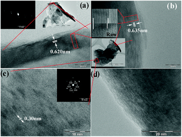
The morphologies of the raw and the as-prepared restacked MoS2 are shown in Fig. 1. The estimated c-axis parameter of the raw material is 0.620 nm and 0.635 nm for restacked MoS2. The zone axis of the selected area electron diffraction (SAED) pattern of the inset in (a) is close to [100]. The normal of the stacked layers is parallel to [001]. In a direct comparison of raw and restacked MoS2 in the top inset to (b), which shows nine layers, an obviously enlarged spacing for the restacked material can be seen. Fig. 1(c) shows the basal plane (001) of the restacked MoS2, and the estimated plane spacing d100 is about 0.30 nm. The zone axis of the SAED pattern is [001], which shows a typical hexagonal structure. Fig. 1(d) shows a very clear c axis ordering with distortion and dislocation, indicating that the restacking of MoS2 layers is turbostratic.
 | ||
| Fig. 1 Transmission electron microscope (TEM) images of raw and restacked MoS2: (a) raw MoS2, with the inset showing the corresponding SAED pattern; (b) restacked MoS2, with the top inset showing a direct comparison of the layer spacing of raw and restacked MoS2 by a comparison of 9 layers, while the bottom inset indicates the particle source of the images enlarged in (b) and (c); (c) restacked MoS2, with the inset showing the corresponding SAED pattern; (d) turbostratically restacked MoS2. | ||
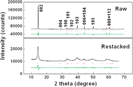
Both raw and restacked MoS2 samples are single phase, as determined by the X-ray diffraction (XRD) patterns shown in Fig. 2. All reflections are in good agreement with a hexagonal structure (JCPDS No. 37-1492) which belongs to the space group P63/mmc (No. 194). The raw material shows very sharp peaks with very high intensity, indicating good crystallization. The strong [002] peak (14.4°) signifies a well-stacked layered structure.12 The restacked sample shows broadened peaks and a shortened [002] peak, which is consistent with previous reported restacked or partially exfoliated MoS2,13,14 suggesting that the mean crystallite size of the restacked MoS2 is much smaller than that of the raw MoS2. The broadened [00l] and [10l] peaks also indicate a reduced number of layers along the z-axis perpendicular to the atomic layers in Fig. S1 (d).† The Rietveld refinement of the XRD pattern fits the experimental data well. The lattice parameters of the raw material can be determined to be a = b = 3.159(1) Å, c = 12.291(2) Å, which are in good agreement with the standard values cited previously. The corresponding parameters of the restacked MoS2 are a = b = 3.129(6) Å, c = 12.526(8) Å (Bragg R-factor = 7.15, Rf-factor = 7.93). The great increase in the c-axis parameter of restacked MoS2, by as much as 0.235 Å, indicates a larger space for lithium ions entering the S slab. On the other hand, the smaller size of the restacked MoS2 compared to that of the raw material, might result in relaxation of the d spacing enlargement effect, resulting in improvements in the electrochemical stability of MoS2. The Raman spectrum of the restacked MoS2 is almost the same as that of the raw MoS2 in the frequency range of 200 to 1000 cm−1, confirming that the single layers of MoS2 have restacked during hydrothermal process (ESI Fig. S2).†
 | ||
| Fig. 2 Rietveld refinement of XRD patterns of raw (top) and restacked (bottom) MoS2. The observed pattern, the calculated peak positions, and the difference between the observed and the calculated patterns are shown in black, red and green, respectively, from top to bottom. | ||
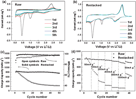
In spite of their attractive capacity, none of the MoS2electrodes previously reported shows both high lithium storage and good capacity retention over the studied voltage range (0.01–3.0 V).6,15,16 When MoS2 is cycled between 3.0 and 0.01 V as an anode material, two step reactions occur. First, lithium intercalates into the S slab, and the van der Waals S–S bonds must be broken to be replaced by Li–S bonds. MoS2 then decomposes into Mo nanoparticles embedded in a Li2S matrix, corresponding to two cathodic peaks at about 1.0 V and 0.4 V in the first cathodic segment in the cyclic voltammograms (CVs), as shown in Fig. 3(a) and (b). Both the raw and the restacked samples show these two peaks. In the following cycles, an extra peak at about 2.0 V appears. This change can be explained by the formation of a gel -like polymeric layer.6In situX-ray diffraction patterns have indicated that lithium intercalation at about 1.0 V corresponds to a phase change.17 When lithium ions enter the S layers, the MoS2 structure changes from 2H to 1T, namely from trigonal prismatic to octahedral, as illustrated in Fig. S1.† The following MoS2decomposition reaction applies:
| MoS2 + 4Li ↔ Mo + 2Li2S | (3) |
 | ||
| Fig. 3 Electrochemical properties of raw and restacked MoS2: cyclic voltammograms of (a) raw and (b) restacked MoS2 at a scanning rate of 0.2 mV s−1; (c) cycling performances at a current density of 50 mA g−1; (d) rate capabilities at different current densities (discharge current density was kept at 50 mA g−1). | ||
The restacked MoS2electrode after cycling was characterized by TEM and XRD, as shown in ESI Fig. S4.† The reduction of crystallite size of the restacked MoS2 after cycling, down to about 10 nm, is believed to be due to the electrochemically-driven grinding and size-reduction of the initial particles. The SAED pattern comprises a diffuse set of rings/diffuse bright spots indicating the very small size of crystallites and lattice defects. No obvious peaks can be observed from 10o to 40° in the ex situXRD pattern, consistent with the nanoparticle nature of the electrochemically formed species.19
In order to evaluate the effect of the enlarged c parameter on reducing the activation energy for Li+ motion and to understand the electrode kinetics, the apparent activation energies of the raw and restacked MoS2 were calculated from electrochemical impedance spectra.20,21 The relevant results are shown in ESI Fig. S5, S6, S7 and Table S1.† The activation energies of the raw and restacked MoS2 at 1.6 V are calculated to be 68.3 and 63.3 kJ mol−1, respectively. When discharged to 0.9 V, the activation energies are 63.5 and 41.5 kJ mol−1, respectively. The activation energy of the restacked MoS2 is slightly smaller than that of the raw material at 1.6 V, which means a faster Li diffusion. However at 0.9 V, there is a phase transition from the pristine 2H form to the 1T form when Li intercalates into the S slabs and the molybdenum atoms change from trigonal prismatic coordination to octahedral coordination. The activation energy for the restacked MoS2 is much smaller than that of the raw materials. This is quite consistent with the previous analysis that the motivation barrier to Li+ motion is reduced when the space around Li increases and the diffusion length for lithium ions are shortened due to the decrease of the crystallite size, especially for high current charge process.
In summary, we have prepared restacked MoS2 with an enlarged c-axis parameter by exfoliation and then restacking by a simple hydrothermal method. The enlarged c parameter and the increase of surface area are favorable to the intercalation reaction, which can also be proven by electrochemical kinetic analysis. The restacked MoS2electrodes exhibit a large capacity of 800 mAh g−1 and extraordinarily high cycling stability, even at high charge current density. The present results suggest that the restacked MoS2 is a promising anode material for lithium ion batteries. The strategy, i.e. enlarging the space between layers and increasing the surface area (especially edge area) for electrode materials with layered structures, could be a common way to improve the intercalation kinetics in terms of rechargeable batteries.
This work was financially supported by the Australian Research Council (ARC) through an ARC Discovery project (DP0878611). Moreover, the authors would like to thank Dr Tania Silver for critical reading of the manuscript and valuable remarks.
Notes and references
- K. Kang, Y. S. Meng, J. Breger, C. P. Grey and G. Ceder, Science, 2006, 311, 977 CrossRef CAS.
- E. Benavente, M. A. Santa Ana, F. Mendizabal and G. Gonzalez, Coord. Chem. Rev., 2002, 224, 87 CrossRef CAS.
- F. Wypych and R. Schollhorn, J. Chem. Soc., Chem. Commun., 1992, 19, 1386 Search PubMed.
- K. D. Bronsema, J. L. de Boer and F. Jellinek, Z. Anorg. Allg. Chem., 1986, 540, 15 CrossRef.
- B. Schoenfeld, J. J. Huang and S. C. Moss, Acta Crystallogr., Sect. B: Struct. Sci., 1983, 39, 404 CrossRef.
- Q. Wang and J. H. Li, J. Phys. Chem. C, 2007, 111, 1675 CrossRef CAS.
- J. Chen, Z. L. Tao and S. L. Li, Angew. Chem., Int. Ed., 2003, 42, 2147 CrossRef CAS.
- M. S. Whittingham, Science, 1976, 192, 1126 CAS.
- M. A. Santa Ana, V. Sanchez and G. Gonzalez, Electrochim. Acta, 1994, 40, 1773.
- R. Bissessur and W. White, Mater. Chem. Phys., 2006, 99, 214 CrossRef CAS.
- J. Heising and M. G. Kanatzidis, J. Am. Chem. Soc., 1999, 121, 11720 CrossRef CAS.
- M. Chhowalla and G. A. J. Amaratunga, Nature, 2000, 407, 164 CrossRef CAS.
- P. Joensen, R. F. Frindt and S. R. Morrison, Mater. Res. Bull., 1986, 21, 457 CrossRef CAS.
- P. Joensen, E. D. Crozier, N. Alberding and R. F. Frindt, J. Phys. C: Solid State Phys., 1987, 20, 4043 CrossRef CAS.
- H. Li, W. J. Li, L. Ma, W. X. Chen and J. M. Wang, J. Alloys Compd., 2009, 471, 442 CrossRef CAS.
- C. Q. Feng, J. Ma, H. Li, R. Zeng, Z. P. Guo and H. K. Liu, Mater. Res. Bull., 2009, 44, 1811 CrossRef CAS.
- M. A. Py and R. R. Haering, Can. J. Phys., 1983, 67, 76.
- J. Zhang, J. M. Soon, K. P. Loh, J. H. Yin, J. Ding, M. B. Sullivian and P. Wu, Nano Lett., 2007, 7, 2370 CrossRef CAS.
- Y. Sharma, N. Sharma, G. V. Subba Rao and B. V. R. Chowdari, Adv. Funct. Mater., 2007, 17, 2855 CrossRef CAS.
- H. Ma, S. Y. Zhang, W. Q. Ji, Z. L. Tao and J. Chen, J. Am. Chem. Soc., 2008, 130, 5361 CrossRef CAS.
- S. L. Chou, J. Z. Wang, J. Z. Sun, D. Wexler, M. Forsyth, H. K. Liu, D. R. MacFarlane and S. X. Dou, Chem. Mater., 2008, 20, 70.
Footnote |
| † Electronic supplementary information (ESI) available: 1: Experimental characterization. 2: Crystal structure. 3: Raman spectra. 4: Magnetic measurements. 5: TEM and XRD of cycled restacked MoS2. 6: EIS spectra. 7: Equivalent circuit. 8: Fitting line. 9: Calculated activation energy data. See DOI: 10.1039/b920277c |
| This journal is © The Royal Society of Chemistry 2010 |
