 Open Access Article
Creative Commons Attribution 3.0 Unported Licence
Electrochemical C–N coupling with perovskite hybrids toward efficient urea synthesis†
Menglei
Yuan
ab,
Junwu
Chen
ab,
Yiling
Bai
cd,
Zhanjun
Liu
c,
Jingxian
Zhang
ab,
Tongkun
Zhao
ab,
Qiaona
Shi
e,
Shuwei
Li
a,
Xi
Wang
 fg and
Guangjin
Zhang
 *abg
*abg
aCAS Key Laboratory of Green Process Engineering, Beijing Key Laboratory of Ionic Liquids Clean Process, State Key Laboratory of Multiphase Complex Systems, Institute of Process Engineering, Chinese Academy of Sciences, Beijing, 100190, China. E-mail: zhanggj@ipe.ac.cn
bCenter of Materials Science and Optoelectronics Engineering, University of Chinese Academy of Sciences, Beijing, 100049, China
cState Key Laboratory of Coal Conversion, CAS Key Laboratory of Carbon Materials, Institute of Coal Chemistry, Chinese Academy of Sciences, Taiyuan, 030001, China
dSynCat@Beijing, Synfuels China Technology Co. Ltd., Huairou District, Beijing, 101407, China
eSino Shaanxi Nuclear Molybdenum Industry Co. Ltd., Tongguan, 714300, China
fKey Laboratory of Luminescence of Optical Information, Ministry of Education, Beijing Jiaotong University, Beijing, 100044, China
gChemistry and Chemical Engineering Guangdong Laboratory, Shantou, 515031, China
First published on 12th April 2021
Abstract
Electrocatalytic C–N coupling reaction by co-activation of both N2 and CO2 molecules under ambient conditions to synthesize valuable urea opens a new avenue for sustainable development, while the actual catalytic activity is limited by poor adsorption and coupling capability of gas molecules on the catalyst surface. Herein, theoretical calculation predicts that the well-developed built-in electric field in perovskite hetero-structured BiFeO3/BiVO4 hybrids can accelerate the local charge redistribution and thus promote the targeted adsorption and activation of inert N2 and CO2 molecules on the generated local electrophilic and nucleophilic regions. Thus, a BiFeO3/BiVO4 heterojunction is designed and synthesized, which delivers a urea yield rate of 4.94 mmol h−1 g−1 with a faradaic efficiency of 17.18% at −0.4 V vs. RHE in 0.1 M KHCO3, outperforming the highest values reported as far. The comprehensive analysis further confirms that the local charge redistribution in the heterojunction effectively suppresses CO poisoning and the formation of the endothermic *NNH intermediate, which thus guarantees the exothermic coupling of *N![[double bond, length as m-dash]](https://www.rsc.org/images/entities/char_e001.gif) N* intermediates with the generated CO via C–N coupling reactions to form the urea precursor *NCON* intermediate. This work opens a new avenue for effective electrocatalytic C–N coupling under ambient conditions.
N* intermediates with the generated CO via C–N coupling reactions to form the urea precursor *NCON* intermediate. This work opens a new avenue for effective electrocatalytic C–N coupling under ambient conditions.
1 Introduction
Nitrogen (N2), accounting for 78% of the atmosphere, exists in the gaseous form that can't be directly utilized in biology and chemistry fields.1–3 On the other hand, carbon dioxide (CO2) generated from industries and transportation is the principal greenhouse gas causing serious environmental concerns.4–8 Thus, converting N2 and CO2 into value-added fuels and chemical products via the C–N coupling reaction is a promising approach for not only mitigating environmental issues and energy crisis but also high-value utilization of N2 and CO2.9–12 However, the highly stable double-bond (C![[double bond, length as m-dash]](https://www.rsc.org/images/entities/char_e001.gif) O, 806 kJ mol−1) in CO2 molecules and the triple-bond (N
O, 806 kJ mol−1) in CO2 molecules and the triple-bond (N![[triple bond, length as m-dash]](https://www.rsc.org/images/entities/char_e002.gif) N, 940.95 kJ mol−1) in N2 molecules make the inert gas molecules difficult to activate mildly.13–17 Although conventional industrial processes such as the Haber–Bosch method and carbon capture and sequestration achieve the activation of inert gas molecules, their further utilization is impeded by the large energy consumption and complex synthetic processes.18–22 In comparison, energy-saving and environmentally benign electrocatalysis technologies such as the nitrogen reduction reaction (NRR) and the carbon dioxide reduction reaction (CO2RR) are drawing growing attention.23–30 Besides, the emerged electrochemical C–N coupling reaction may provide a new possibility of enhancing the spectrum of products of CO2 by using CO2 and amine derivatives/nitrogen sources (nitrate, nitrite, NO, and even N2) as feedstock.9,31,32
N, 940.95 kJ mol−1) in N2 molecules make the inert gas molecules difficult to activate mildly.13–17 Although conventional industrial processes such as the Haber–Bosch method and carbon capture and sequestration achieve the activation of inert gas molecules, their further utilization is impeded by the large energy consumption and complex synthetic processes.18–22 In comparison, energy-saving and environmentally benign electrocatalysis technologies such as the nitrogen reduction reaction (NRR) and the carbon dioxide reduction reaction (CO2RR) are drawing growing attention.23–30 Besides, the emerged electrochemical C–N coupling reaction may provide a new possibility of enhancing the spectrum of products of CO2 by using CO2 and amine derivatives/nitrogen sources (nitrate, nitrite, NO, and even N2) as feedstock.9,31,32
The desired product urea [CO(NH2)2] will be produced when the electrochemical C–N bond formation occurs by employing both N2 and CO2 as the feeding gas.9 Urea is commonly utilized as the general feedstock in industry and the primary fertilizer for agriculture.33,34 The industrial urea synthesis proceeds by two consecutive processes, including N2 + H2 → NH3 followed by NH3 + CO2 → CO(NH2)2, which operate under harsh reaction conditions (350–550 °C, 150–350 bar and 150–200 °C, 150–250 bar, respectively).35 Compared with the complex industrial synthetic process, simultaneous electrocatalytic fixation of N2 and CO2 driven by a renewable energy source under ambient conditions provides a clean route for urea production.9 The main issues in electrochemical synthesis of urea lie in three aspects: (1) extraordinarily weak chemical adsorption of inert CO2/N2 on the catalysts surface;29,30,36,37 (2) the dissociation of the highly stable C![[double bond, length as m-dash]](https://www.rsc.org/images/entities/char_e001.gif) O bond and N
O bond and N![[triple bond, length as m-dash]](https://www.rsc.org/images/entities/char_e002.gif) N bond requires high overpotential;13,15 (3) the parallel reaction of CO2/N2 reduction suppresses the efficiency of C–N coupling and strongly competes with the desired urea formation reaction, further resulting in a large distribution of complex products.9
N bond requires high overpotential;13,15 (3) the parallel reaction of CO2/N2 reduction suppresses the efficiency of C–N coupling and strongly competes with the desired urea formation reaction, further resulting in a large distribution of complex products.9
Although a few noble metal Pd-based catalysts can achieve urea electrosynthesis, the related catalytic activity showed a maximum urea yield rate of 3.36 mmol h−1 g−1 with a FE of 8.92%.9 Besides, the high price and scarcity of the used noble metals impede their real application on the large scale. Thus, further improvement of the catalytic activity with earth-abundant materials remains a challenge. Inspired by the different electronic structures of N2 and CO2 molecules, tuning the electronic state of the electrocatalyst's surface can be a feasible strategy to optimize the adsorption of reactant gas molecules and suppress the competing electro-reduction reactions to promote urea generation. In this regard, fabricating a built-in electronic field to accelerate the local charge redistribution in perovskite heterostructures displays fascinating potential to deliver impressive urea electroproduction activity. On the one hand, perovskite structured transition-metal oxide (ABO3) semiconductors possess a distinctive electronic structure, which can lead to the alteration of electron density when combining with other domains.38,39 On the other hand, the work function difference in perovskite heterostructures drives the local charge redistribution by the band bending at the heterointerface, which is preferred for targeted adsorption and activation of inert small molecules such as N2, CO2, H2O, and so on.40 Despite the encouraging merits, inducing the local charge redistribution in perovskite hybrids toward the specific urea electrosynthesis hasn't been explored.
In this work, with the aid of theoretical simulation, we exploited perovskite structured p-type BiFeO3 and an n-type semiconductor BiVO4 to fabricate innovative p–n heterojunction electrocatalysts, aiming at enabling spontaneous electron transfer at the heterointerfaces by the desirable built-in electric field. The obtained perovskite structured BiFeO3/BiVO4 showed high electrocatalytic activity toward the C–N coupling reaction to synthesize urea, and exhibits a FE of 17.18% in 0.1 M KHCO3 at −0.4 V vs. RHE. The urea yield rate can reach 4.94 mmol h−1 g−1 which is much higher than the recently reported best values with Pd-based electrocatalysts. The activity can further be improved by adding an ionic liquid to the electrolyte. The generated local electrophilic and nucleophilic regions enhanced the targeted adsorption and activation of inert N2 and CO2 molecules and balanced the competing electro-reduction reactions to further promote the formation of the *NCON* intermediate via the C–N bond coupling reaction. Thus, engineering a built-in electric field to facilitate local charge redistribution has been proposed as an appealing strategy to enhance electrocatalytic C–N bond coupling and further urea synthesis.
2 Results and discussion
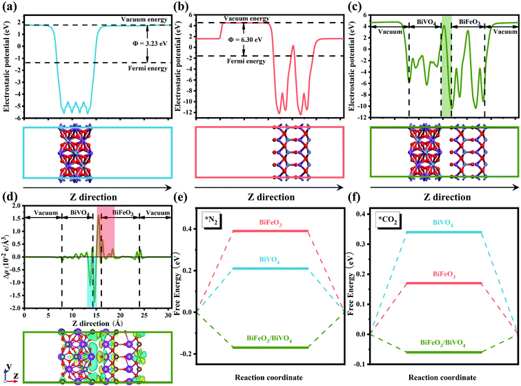
Conspicuously, the charged surface can give rise to a significant effect on the targeted adsorption of reactant molecules.30 In this regard, constructing built-in fields at the heterointerface to promote a spontaneous electron transfer process will supply more possibilities for generating desirable two opposite charged regions.41 This design concept has been confirmed by the investigation of various perovskite-based semiconductor catalysts, which can constitute distinct p–n junctions and thus accelerate local charge redistribution at the heterointerface.40 The band theory of solids has confirmed that the behavior of electron transfer is strongly correlated to the work function of semiconductors.42 As presented in Fig. 1a and b, the theoretical simulation results showed that the work function values of BiVO4 and BiFeO3 were 3.23 eV and 6.30 eV, respectively, which allow self-driven electron transfer from BiVO4 to BiFeO3. The profile of the planar averaged electrostatic potential along the z-direction for BiFeO3/BiVO4 hybrids is depicted in Fig. 1c. Compared with pristine BiVO4 and BiFeO3 that possess periodic lattice potential, BiFeO3/BiVO4 hybrids showed a big build-in potential at the interfaces. Additionally, electron density difference calculation was further performed to reveal the charge distribution at the interface of BiFeO3/BiVO4 hybrids. As described in Fig. 1d, the charge depletion and accumulation are represented by the cyan region and yellow region, respectively. An increase of the charge density was observed at the BiFeO3 surface and a decrease at the BiVO4 surface, which confirmed that the spontaneous electron transfer induced the local charge redistribution around the interface and endowed the surfaces of BiFeO3 and BiVO4 with local nucleophilic and electrophilic regions. Bader analysis results further demonstrate that BiVO4 can transfer 2.33 electrons to BiFeO3. Previous research has proven that the chemisorption of inert CO2 and N2 is the initial step for electrocatalytic urea production. As shown in Fig. S1,† the N atom in the N2 molecule and the C atom in the CO2 molecule are electron-rich and electron-deficient, respectively. Therefore, it can be deduced that the rationally designed BiFeO3/BiVO4 hybrids with local nucleophilic and electrophilic regions would adsorb targeted reactant molecules by electrostatic interaction. To confirm the above hypothesis, density functional theory (DFT) calculations were performed to reveal the gas adsorption behavior on the surface of the electrocatalyst. As expected, the calculated adsorption energies of BiFeO3/BiVO4 hybrids for N2 and CO2 are −0.17 eV and −0.06 eV, much lower than those of individual architectures of BiFeO3 and BiVO4 (Fig. 1e and f), proving that N2 and CO2 show a stronger tendency to adsorb on the surface of BiFeO3/BiVO4 hybrids than on pristine BiFeO3 and BiVO4 due to the interfacial interaction triggered by the well-defined space-charge region, which is favorable for much readily chemisorbing inert gas molecules and thus facilitating the electrocatalytic urea production process.As a proof-of-concept experiment, perovskite structured BiFeO3/BiVO4 hybrids were designed and synthesized by the facile ultrasonic bath method. The field-emission scanning electron microscopy (FE-SEM) image in Fig. 2a reveals that BiFeO3/BiVO4 heterostructures possess a rice-like morphology with an average length of 1 μm and a diameter of approximately 400 nm, respectively. The relevant elemental mapping demonstrates the evenly distributed Bi, Fe, V, and O elements. In comparison, pristine BiVO4 still maintains the same morphology as heterostructured hybrids (Fig. 2c), whereas the BiFeO3 displays an irregular nanoparticle structure (Fig. 2b). As surveyed by high-resolution transmission electron microscopy (HR-TEM), the well-resolved lattice fringes of 0.282 nm and 0.312 nm corresponded to the (104) plane and (130) plane of BiFeO3 and BiVO4 crystals (Fig. 2e). Meanwhile, the distinct interface generated by the intimate contact of BiFeO3 and BiVO4 confirms the representative establishment of nanoscale heterostructures (Fig. 2d).
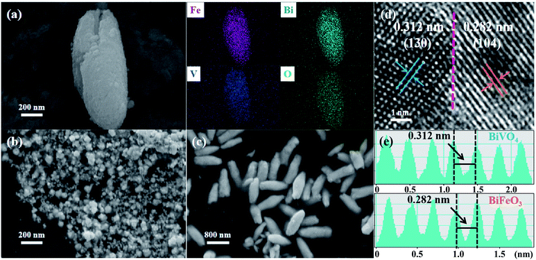 | ||
| Fig. 2 (a) SEM image and the corresponding elemental mapping of BiFeO3/BiVO4 hybrids; SEM images of (b) BiFeO3 and (c) BiVO4; (d) high-resolution TEM image of BiFeO3/BiVO4 hybrids and the dotted line represents the heterointerfaces; (e) the well-resolved lattice fringe of BiFeO3/BiVO4 hybrids in Fig. 2d. | ||
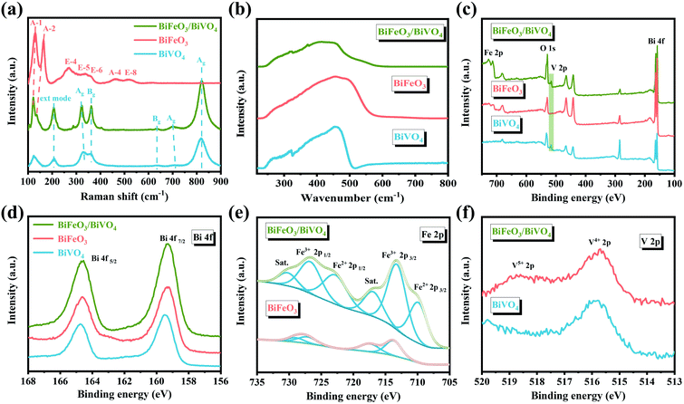
In Fig. 3a and b, the XRD spectra show that the hexagonal BiFeO3 structure (JCPDS: 86-1518) and monoclinic BiVO4 phase (JCPDS: 83-1700) can be obtained in pristine BiFeO3 and BiVO4 samples. Concerning BiFeO3/BiVO4 hybrids, both sets of diffraction peaks are consistent with those of pristine samples, except for the slight shift of the characteristic peaks of BiFeO3 and partial peaks of BiVO4 to higher diffraction angles (Fig. 3c), which indicates the possible interaction between the two distinct domains.43,44 As further revealed by Mott–Schottky (M–S) curves, BiFeO3 with a negative slope (Fig. 3d) and BiVO4 with a positive slope (Fig. 3e) matched well with the apparent characteristics of a p-type and an n-type semiconductor, respectively. In comparison, the as-prepared BiFeO3/BiVO4 hybrids exhibited evident p–n heterojunction features (Fig. 3f), which furnish the rational architecture to achieve the desired local charge redistribution by the above theoretical prediction. In Raman spectra (Fig. 4a), the typical vibrational bands at 137 and 171 cm−1 represent the Fe–O–Fe bonds of the BiFeO3 sample,45,46 whereas they exhibit a slightly negative shift accompanied by an intensity decrease when coupled with BiVO4 domains. Likewise, the detected V–O stretching modes (637, 702, and 826 cm−1) and VO43− tetrahedron bending modes (327 and 367 cm−1) also negatively shifted after the establishment of the heterostructure with the space-charge region.47–49 This broadening of vibrational modes and position shifting in BiFeO3/BiVO4 hybrids manifest the intense coupling interaction between BiFeO3 and BiVO4.50,51 Besides, compared to the UV-Vis spectrum of pristine samples, the dominant peak in BiFeO3/BiVO4 hybrids exhibited an obvious blue shift, evidencing the existence of the charge transfer effect (Fig. 4b).52 To further reveal the electronic effects between BiFeO3 and BiVO4, the chemical components and the alteration of valence states in the formed catalysts were further examined by X-ray photoelectron spectroscopy (XPS). The survey spectra, displayed in Fig. 4c, illustrate the presence of Bi, Fe, V, and O elements in the obtained electrocatalysts, which is consistent with the above SEM characterization. The high-resolution Bi 4f spectrum displayed two predominant peaks of Bi3+ 4f7/2 and Bi3+ 4f5/2 at the binding energies of 159.3 eV and 164.7 eV (Fig. 4d).53,54
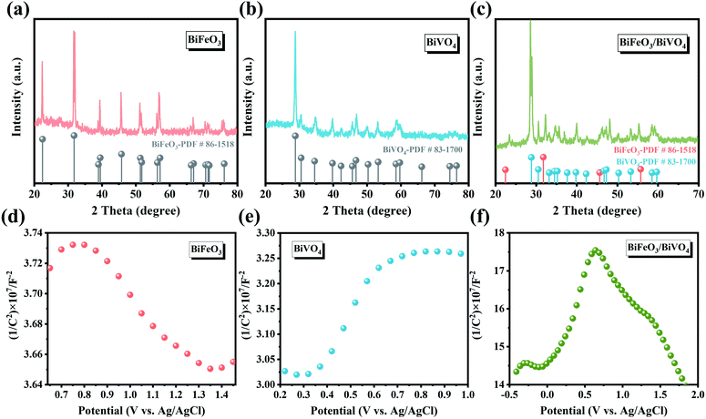 | ||
| Fig. 3 XRD patterns of (a) BiFeO3, (b) BiVO4 and (c) BiFeO3/BiVO4; Mott–Schottky plots of (d) BiFeO3, (e) BiVO4 and (f) BiFeO3/BiVO4. | ||
Besides, two distinct peaks centered at 713.4 eV and 726.9 eV in the Fe 2p region can be attributed to the binding energies of Fe3+ 2p3/2 and Fe3+ 2p1/2, respectively (Fig. 4e).55,56 And the XPS peak positioned at 515.8 eV in the V 2p spectrum illustrates the presence of V4+ (Fig. 4f). It is noteworthy that when BiFeO3 was coupled with BiVO4, the emerged new peaks in BiFeO3/BiVO4 hybrids are assigned to Fe2+ 2p and V5+ 2p peaks in contrast to pristine samples, elucidating that the apparent electronic interactions between BiFeO3 and BiVO4 domains are due to the formation of p–n heterojunctions.57,58 More importantly, the related changes in the valence state further demonstrate that the charge transferred from BiVO4 to BiFeO3. All these results convincingly suggest the successful establishment of unique p–n heterojunctions and the transfer of electrons between BiVO4 and BiFeO3. The induced local charge redistribution contributes to the targeted adsorption of reactant molecules and thus enhances the electrocatalytic urea production ability.
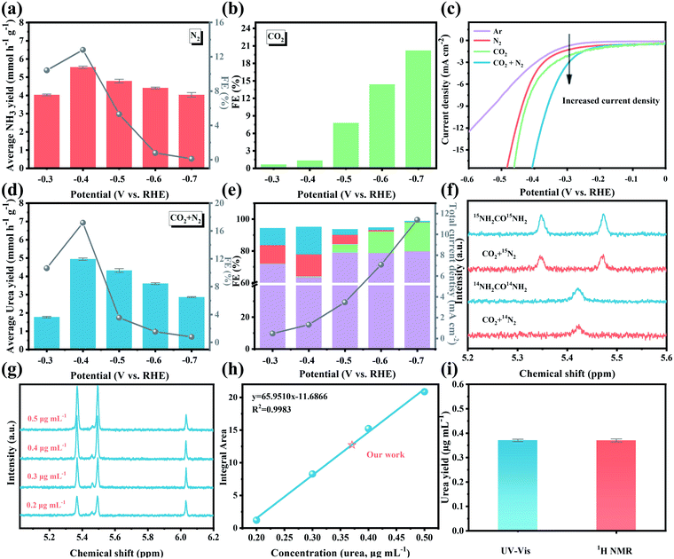
The electrocatalytic activity of BiFeO3/BiVO4 hybrids for the C–N coupling reaction toward urea production was tested in a 0.1 M KHCO3 solution utilizing an H-type two-compartment cell separated by a Nafion 211 membrane, which is equipped with a three-electrode configuration (Fig. S2†). Ultrahigh purity CO2 gas (99.999%) and N2 gas (99.999%) were continuously purged into the cathodic chamber with the same flow rate of 5 mL min−1 during the electrolysis process. The possibly generated liquid products (urea and NH3) in the electrolytes were spectrophotometrically measured by the diacetyl monoxime method and indophenol blue method.22,59 Meanwhile, the related calibration curves are displayed in Fig. S3.† Besides, online gas chromatography monitored the possible gas products such as CO and H2. It has been reported that the electrochemical catalytic activity of the C–N coupling reaction for urea production was dominant as a result of effectively coupling the carbon dioxide reduction reaction (CO2RR) with the nitrogen reduction reaction (NRR). As displayed in Fig. 5a and b, the BiFeO3/BiVO4 hybrids possess a high NH3 faradaic efficiency (FE) (12.81%) for the NRR and CO FE (20.21%) for the CO2RR, which establish the baseline of N2 and CO2 reduction activity. The linear sweep voltammetry curves (LSV) were initially examined in 0.1 M KHCO3 saturated with different gas feeds (Ar, CO2, N2, or CO2 + N2). As depicted in Fig. 5c, the distinctly enhanced current density in CO2 + N2 saturated electrolyte relative to that in CO2 and N2, respectively, indicates the occurrence of the electrocatalytic C–N coupling reaction for urea production. A potentiostatic experiment was further performed to quantitatively assess the performance of electrocatalytic urea production of BiFeO3/BiVO4 hybrids at different working potentials. As shown in Fig. S4,† the corresponding chronoamperometry curves within the potential range of −0.3 V to −0.7 V exhibit stable current density after electrolysis for 2 h. As demonstrated in Fig. 5d, the urea yield rate and the corresponding FE increase with the increase of applied potential. The highest urea yield rate is 4.94 mmol h−1 g−1 with a FE of 17.18% at −0.4 vs. the reversible hydrogen electrode (RHE), outperforming all the reported values for Pd based catalysts (Table S1†). However, at more negative potentials, the electrocatalytic urea production performance decreases, which may result from the occupation of the active sites for N2 and CO2 reduction by the excessively released CO (Fig. 5e). Additionally, the as-obtained BiFeO3/BiVO4 hybrids retain 96% of the initial current density after a 10 h long-term chronopotentiometry test (Fig. S5†). Likewise, when conducting five cycling tests, negligible change is observed in the electrocatalytic urea production performance (Fig. S6†), attesting to the superior electrocatalytic stability of BiFeO3/BiVO4 hybrids. The corresponding characterization studies further reveal that the BiFeO3/BiVO4 hybrids were well-matched with their original morphology, crystal phase, and chemical states after 10 h of continuous electrolysis (Fig. S7†), corroborating their robust structural stability. Impressively, with the aid of enhanced CO2 adsorption capacity of an ionic liquid,60 when the 1-butyl-3-methylimidazolium tetrafluoroborate–KHCO3 ([Bmim]BF4–KHCO3) electrolyte was used in the system, a higher electrocatalytic activity for urea production is achieved (FE: 20.75%, urea yield rate: 5.42 mmol h−1 g−1) than that obtained in pristine KHCO3 solution at the same potential (Fig. S8†).
To gain solid proof that the produced urea originated from the C–N coupling reaction with CO2 and N2, a rigorous protocol was employed to avoid false-positive results caused by the contamination of environmental NOX (Fig. S9†). Under all the control experiment conditions, negligible urea was detected, which excludes the possible effect of environmental NOX on the urea electrosynthesis (Fig. S10†). 15N2 isotopic labeling experiment was further utilized to corroborate the N source of the generated urea [CO(NH2)2]. The standard CO(15NH2)2 sample displays two dominant peaks at approximately 5.35 ppm and 5.47 ppm in 1H Nuclear Magnetic Resonance (NMR) (Fig. 5f), while the standard CO(14NH2)2 sample possesses one distinct peak at about 5.42 ppm. When utilizing 15N2 and CO2 as the feed gas, the detected 1H NMR signals of the produced urea matched well with the standard CO(15NH2)2 signals. Additionally, the concentration of CO(15NH2)2 was also quantitatively detected by 1H NMR, and the related signal integration–concentration linear relation is exhibited in Fig. 5g and h. As expected, the calculated urea concentration is consistent with the quantitative results of the diacetyl monoxime method (Fig. 5i). All these results are convincingly indicative of urea originating from the C–N coupling reaction from N2 and CO2 catalyzed by BiFeO3/BiVO4 hybrids.
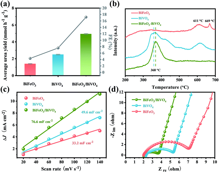
For comparison, the pristine BiFeO3 and BiVO4 were also evaluated under identical conditions. At the optimal potential of −0.4 V, the electrocatalytic activities of BiFeO3 (urea yield rate: 1.41 mmol h−1 g−1, FE: 4.35%) and BiVO4 (urea yield rate: 2.50 mmol h−1 g−1, FE: 7.59%) were much inferior to those of BiFeO3/BiVO4 hybrids for urea production (Fig. 6a). This indicates that the local charge redistribution in BiFeO3/BiVO4 hybrids plays a critical role in enhancing electrocatalytic urea production. As revealed by temperature-programmed desorption (TPD), compared with pristine BiFeO3 and BiVO4, BiFeO3/BiVO4 hybrids exhibited stronger binding strength and larger desorption peak in the CO2- and N2-TPD spectra (Fig. 6b and S11†), elucidating that the local charge redistribution in BiFeO3/BiVO4 hybrids endows the surfaces of BiFeO3 and BiVO4 with local nucleophilic and electrophilic regions and thus promotes the targeted adsorption of CO2 and N2 molecules, which is in good agreement with the aforementioned theoretical prediction. The electrochemically active surface area (ECSA) results suggest that the BiFeO3/BiVO4 hybrids (76.6 mF cm−2) display a higher electrochemical double-layer capacitance (Cdl) than pristine BiFeO3 (33.2 mF cm−2) and BiVO4 (49.6 mF cm−2), which signifies that local charge redistribution promotes the exposure of more active sites in BiFeO3/BiVO4 hybrids for gas molecule adsorption and activation (Fig. 6c and S12†). Electrochemical impedance spectroscopy (EIS) analysis further reveals that the BiFeO3/BiVO4 hybrids possess a smaller semicircle and higher slope than pristine samples, evincing that the presence of local charge redistribution in BiFeO3/BiVO4 hybrids significantly promotes electron/ion transfer kinetics during the electrocatalytic process (Fig. 6d).29,43
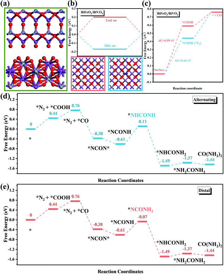
To obtain deeper insight into the C–N coupling reaction mechanism toward the electrocatalytic urea production, DFT calculation was further employed to assess the intermediate variation and energy barrier during the reaction process. The corresponding BiFeO3/BiVO4 heterostructured architecture is displayed in Fig. 7a. Since the chemisorption of inert CO2 and N2 molecules is the initial step for electrocatalytic urea production, it is critical to reveal the competitive adsorption between these gas molecules. In comparison with CO2-TPD, the peaks in the N2-TPD spectrum of the heterostructured hybrids appeared at a higher temperature and exhibited enhanced intensity, demonstrating that the BiFeO3/BiVO4 hybrids possessed stronger N2 chemisorption ability than that for CO2 molecules (Fig. 6c and S11†).9 In other words, the C–N coupling reaction was initiated with chemisorption of N2 molecules on the BiFeO3/BiVO4 hybrids. Besides, the free energy of the N2 adsorption with a side-on configuration was more negative than that of an end-on configuration, suggesting that N2 preferably adsorbed on the local electrophilic BiVO4 regions via the more stable side-on configuration (Fig. 7b). Impressively, as identified in Fig. 7c, the BiFeO3/BiVO4 hybrids required the highest Gibbs free energy (ΔG) of 0.59 eV to reduce CO2, while the ΔG decreased to 0.44 eV when the N2 molecules emerged in neighboring BiVO4 regions. Therefore, it can be deduced that the adsorbed/activated N2 molecules would facilitate the reduction of adsorbed CO2 to CO on local nucleophilic BiFeO3 regions. Then the C–N coupling reaction spontaneously occurred between the activated N2 molecules (*N![[double bond, length as m-dash]](https://www.rsc.org/images/entities/char_e001.gif) N*) and in situ generated CO to form the *NCON* intermediate, due to the matching molecular orbitals. The corresponding ΔG further corroborates that the formation of the *NCON* intermediate is an exothermic process. Once the *NCON* intermediate is generated, the subsequent hydrogenation of *NCON* would produce two possible reaction pathways involving distal and alternating mechanisms. Concerning the alternating pathway, the (H+ + e−) alternately reacted with the two N atoms, while the protonation continuously attacked the distal N atoms for the distal mechanism. As displayed in Fig. 7d and e, when the reduction of *NCON* follows the distal pathway, the required ΔG decreased to 0.54 eV compared to that of the alternating pathway (0.72 eV), suggesting that the BiFeO3/BiVO4 hybrids were prone to pursue the distal mechanism until the release of urea molecules rather than the alternating pathway from the thermodynamic perspective.31
N*) and in situ generated CO to form the *NCON* intermediate, due to the matching molecular orbitals. The corresponding ΔG further corroborates that the formation of the *NCON* intermediate is an exothermic process. Once the *NCON* intermediate is generated, the subsequent hydrogenation of *NCON* would produce two possible reaction pathways involving distal and alternating mechanisms. Concerning the alternating pathway, the (H+ + e−) alternately reacted with the two N atoms, while the protonation continuously attacked the distal N atoms for the distal mechanism. As displayed in Fig. 7d and e, when the reduction of *NCON* follows the distal pathway, the required ΔG decreased to 0.54 eV compared to that of the alternating pathway (0.72 eV), suggesting that the BiFeO3/BiVO4 hybrids were prone to pursue the distal mechanism until the release of urea molecules rather than the alternating pathway from the thermodynamic perspective.31
The selectivity of the electrocatalytic urea production is closely associated with the formation of *NCON* intermediates. The possible N2 reduction or the excessive release of CO would result in a decrease in the efficiency of the electrocatalytic C–N coupling reaction and further reduce the selectivity. On the one hand, the ΔG for the reductive protonation of *N2 into *N2H (N2 + H+ + e− + * → *NNH), which is regarded as the potential-determining step (PDS) toward the NRR, was calculated to be 0.14 eV (Fig. S13†),61 which was much higher than that for the C–N coupling reaction to form *NCON*. Such a significantly larger energy barrier makes BiFeO3/BiVO4 hybrids inactive for the electrocatalytic NRR, let alone generating side product NH3. On the other hand, the release of the generated *CO intermediate was strongly associated with the selectivity of the electrocatalytic urea production. Thus, the stability of the as-prepared electrocatalysts against CO poisoning was evaluated through an electrochemical CO-stripping experiment. As shown in Fig. S14,† the CO-stripping peak of BiFeO3/BiVO4 hybrids (0.251 V vs. RHE) exhibits a more negative shift than that of pristine BiFeO3 (0.261 V vs. RHE) and BiVO4 counterparts (0.265 V vs. RHE), indicating that the BiFeO3/BiVO4 hybrids possessed higher stability against CO poisoning, which is due to the elimination of some of the strong adsorption sites by the local charge redistribution.62 Notably, the amount of CO should be well controlled. As confirmed by Fig. 5e, when the applied potential exceeded −0.4 V, the excessively released CO occupied the adsorption sites for N2 and CO2 and resulted in a remarkable decrease of the FE for urea production.
By combining the aforementioned experimental results and computational simulations, the overall urea electrosynthesis process can be summarized in the following steps: (i) the built-in electric field in BiFeO3/BiVO4 hybrids accelerates the local charge redistribution, (ii) N2/CO2 molecules first adsorbed on the generated electrophilic/nucleophilic regions by electrostatic interaction, (iii) the produced *N2 promotes CO2 reduction under the electric field, and then the generated CO will further react with *N2 to produce the desirable *NCON* intermediate through exothermic electrocatalytic C–N coupling reaction, and (iv) the subsequent protonation process preferentially undergoes the distal mechanism until the formation of urea (Fig. 8).
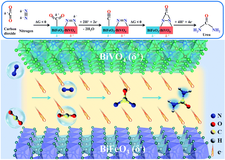 | ||
| Fig. 8 The schematic electrocatalytic urea production mechanism based on BiFeO3/BiVO4 p–n heterostructure synergistic effects. | ||
3 Conclusion
In summary, inspired by the theoretical simulation predictions, a facile ultrasonic bath strategy was proposed to elaborately integrate the perovskite structured BiFeO3 and BiVO4 as a unique p–n heterojunction. The well-developed built-in electric field at the heterointerfaces facilitates the local charge redistribution and thus endows the BiFeO3 and BiVO4 surfaces with local nucleophilic and electrophilic regions, which promote the targeted adsorption and activation of N2 and CO2 molecules. Besides, the local charge redistribution also contributed to fully exposing the active sites and accelerated electrocatalytic kinetics, which is beneficial for the formation of the C–N bond and generation of the desired *NCON* intermediate. As a result, the BiFeO3/BiVO4 hybrids exhibit a maximum urea yield rate and FE of 4.94 mmol h−1 g−1 and 17.18% at −0.4 V vs. RHE in 0.1 M KHCO3. Besides, the related urea yield rate and FE can be further improved to 5.42 mmol h−1 g−1 and 20.75% in (Bmim)BF4–KHCO3 electrolyte. This work proposed an innovative local charge redistribution concept to design urea production catalysts by promoting electrocatalytic C–N bond coupling.Author contributions
The manuscript was written through contributions of all authors. All authors have given approval to the final version of the manuscript.Conflicts of interest
There are no conflicts to declare.Acknowledgements
This work is supported by the National Key R&D Program of China (No. 2020YFA0710200) and the Chemistry and Chemical Engineering Guangdong Laboratory (No. 1922006). We also thank the financial project of the Key Program for International S&T Cooperation Projects (No. 2018YFE0124600) funded by the Ministry of Science and Technology of China.References
- J. W. Erisman, M. A. Sutton, J. Galloway, Z. Klimont and W. Winiwarter, Nat. Geosci., 2008, 1, 636–639 CrossRef CAS.
- K. C. MacLeod and P. L. Holland, Nat. Chem., 2013, 5, 559–565 CrossRef CAS PubMed.
- H.-P. Jia and E. A. Quadrelli, Chem. Soc. Rev., 2014, 43, 547–564 RSC.
- P. Lu, D. Gao, H. He, Q. Wang, Z. Liu, S. Dipazir, M. Yuan, W. Zu and G. Zhang, Nanoscale, 2019, 11, 7805–7812 RSC.
- T.-T. Zhuang, Y. Pang, Z.-Q. Liang, Z. Wang, Y. Li, C.-S. Tan, J. Li, C. T. Dinh, P. De Luna, P.-L. Hsieh, T. Burdyny, H.-H. Li, M. Liu, Y. Wang, F. Li, A. Proppe, A. Johnston, D.-H. Nam, Z.-Y. Wu, Y.-R. Zheng, A. H. Ip, H. Tan, L.-J. Chen, S.-H. Yu, S. O. Kelley, D. Sinton and E. H. Sargent, Nat. Catal., 2018, 1, 946–951 CrossRef CAS.
- S. Nitopi, E. Bertheussen, S. B. Scott, X. Liu, A. K. Engstfeld, S. Horch, B. Seger, I. E. L. Stephens, K. Chan, C. Hahn, J. K. Nørskov, T. F. Jaramillo and I. Chorkendorff, Chem. Rev., 2019, 119, 7610–7672 CrossRef CAS PubMed.
- Z.-Q. Liang, T.-T. Zhuang, A. Seifitokaldani, J. Li, C.-W. Huang, C.-S. Tan, Y. Li, P. De Luna, C. T. Dinh, Y. Hu, Q. Xiao, P.-L. Hsieh, Y. Wang, F. Li, R. Quintero-Bermudez, Y. Zhou, P. Chen, Y. Pang, S.-C. Lo, L.-J. Chen, H. Tan, Z. Xu, S. Zhao, D. Sinton and E. H. Sargent, Nat. Commun., 2018, 9, 3828 CrossRef PubMed.
- Z. Lyu, S. Zhu, M. Xie, Y. Zhang, Z. Chen, R. Chen, M. Tian, M. Chi, M. Shao and Y. Xia, Angew. Chem., Int. Ed., 2021, 60, 1909–1915 CrossRef CAS PubMed.
- C. Chen, X. Zhu, X. Wen, Y. Zhou, L. Zhou, H. Li, L. Tao, Q. Li, S. Du, T. Liu, D. Yan, C. Xie, Y. Zou, Y. Wang, R. Chen, J. Huo, Y. Li, J. Cheng, H. Su, X. Zhao, W. Cheng, Q. Liu, H. Lin, J. Luo, J. Chen, M. Dong, K. Cheng, C. Li and S. Wang, Nat. Chem., 2020, 12, 717–724 CrossRef CAS PubMed.
- D. Gao, R. M. Arán-Ais, H. S. Jeon and B. Roldan Cuenya, Nat. Catal., 2019, 2, 198–210 CrossRef CAS.
- D. M. Weekes, D. A. Salvatore, A. Reyes, A. Huang and C. P. Berlinguette, Acc. Chem. Res., 2018, 51, 910–918 CrossRef CAS PubMed.
- X. Li, T. Li, Y. Ma, Q. Wei, W. Qiu, H. Guo, X. Shi, P. Zhang, A. M. Asiri, L. Chen, B. Tang and X. Sun, Adv. Energy Mater., 2018, 8, 1801357 CrossRef.
- N. Zhang, A. Jalil, D. Wu, S. Chen, Y. Liu, C. Gao, W. Ye, Z. Qi, H. Ju, C. Wang, X. Wu, L. Song, J. Zhu and Y. Xiong, J. Am. Chem. Soc., 2018, 140, 9434–9443 CrossRef CAS PubMed.
- Y. Liu, M. Cheng, Z. He, B. Gu, C. Xiao, T. Zhou, Z. Guo, J. Liu, H. He, B. Ye, B. Pan and Y. Xie, Angew. Chem., Int. Ed., 2019, 58, 731–735 CrossRef CAS PubMed.
- H. B. Yang, S.-F. Hung, S. Liu, K. Yuan, S. Miao, L. Zhang, X. Huang, H.-Y. Wang, W. Cai, R. Chen, J. Gao, X. Yang, W. Chen, Y. Huang, H. M. Chen, C. M. Li, T. Zhang and B. Liu, Nat. Energy, 2018, 3, 140–147 CrossRef CAS.
- P. Lu, J. Zhang, H. He, M. Wang, Z. Luo, D. Gao, Z. Liu, X. Wang, M. Yuan, S. Dipazir, H. Zhao, Y. Xie and G. Zhang, J. Power Sources, 2020, 449, 227496 CrossRef CAS.
- X. Cui, C. Tang and Q. Zhang, Adv. Energy Mater., 2018, 8, 1800369 CrossRef.
- P. M. Glibert, R. Maranger, D. J. Sobota and L. Bouwman, Environ. Res. Lett., 2014, 9, 105001 CrossRef.
- M. Boota and Y. Gogotsi, Adv. Energy Mater., 2019, 9, 1802917 CrossRef.
- C. Tang and S.-Z. Qiao, Chem. Soc. Rev., 2019, 48, 3166–3180 RSC.
- C. J. M. van der Ham, M. T. M. Koper and D. G. H. Hetterscheid, Chem. Soc. Rev., 2014, 43, 5183–5191 RSC.
- M. Yuan, Q. Li, J. Zhang, J. Wu, T. Zhao, Z. Liu, L. Zhou, H. He, B. Li and G. Zhang, Adv. Funct. Mater., 2020, 30, 2004208 CrossRef CAS.
- S. H. Lee, J. C. Lin, M. Farmand, A. T. Landers, J. T. Feaster, J. E. Aviles Acosta, J. W. Beeman, Y. Ye, J. Yano, A. Mehta, R. C. Davis, T. F. Jaramillo, C. Hahn and W. S. Drisdell, J. Am. Chem. Soc., 2020, 143, 588–592 CrossRef PubMed.
- F. Hu, S. C. Abeyweera, J. Yu, D. Zhang, Y. Wang, Q. Yan and Y. Sun, Chem, 2020, 6, 3007–3021 CAS.
- H. Cheng, S. Liu, J. Zhang, T. Zhou, N. Zhang, X.-s. Zheng, W. Chu, Z. Hu, C. Wu and Y. Xie, Nano Lett., 2020, 20, 6097–6103 CrossRef CAS PubMed.
- X. Zhang, Y. Wang, M. Gu, M. Wang, Z. Zhang, W. Pan, Z. Jiang, H. Zheng, M. Lucero, H. Wang, G. E. Sterbinsky, Q. Ma, Y.-G. Wang, Z. Feng, J. Li, H. Dai and Y. Liang, Nat. Energy, 2020, 5, 684–692 CrossRef CAS.
- H. S. Kim, J. Choi, J. Kong, H. Kim, S. J. Yoo and H. S. Park, ACS Catal., 2021, 11, 435–445 CrossRef CAS.
- S. Wang, L. Shi, X. Bai, Q. Li, C. Ling and J. Wang, ACS Cent. Sci., 2020, 6, 1762–1771 CrossRef CAS PubMed.
- M. Yuan, Y. Bai, J. Zhang, T. Zhao, S. Li, H. He, Z. Liu, Z. Wang and G. Zhang, J. Mater. Chem. A, 2020, 8, 26066–26074 RSC.
- M. Yuan, H. Zhang, D. Gao, H. He, Y. Sun, P. Lu, S. Dipazir, Q. Li, L. Zhou, S. Li, Z. Liu, J. Yang, Y. Xie, H. Zhao and G. Zhang, J. Mater. Chem. A, 2020, 8, 2691–2700 RSC.
- M. Yuan, J. Chen, Y. Bai, Z. Liu, J. Zhang, T. Zhao, Q. Wang, S. Li, H. He and G. Zhang, Angew. Chem., Int. Ed., 2021 DOI:10.1002/anie.202101275.
- M. Jouny, G. S. Hutchings and F. Jiao, Nat. Catal., 2019, 2, 1062–1070 CrossRef CAS.
- J. Qiao, Y. Liu, F. Hong and J. Zhang, Chem. Soc. Rev., 2014, 43, 631–675 RSC.
- M. Aresta, A. Dibenedetto and A. Angelini, Chem. Rev., 2014, 114, 1709–1742 CrossRef CAS PubMed.
- D. B. Kayan and F. Köleli, Appl. Catal., B, 2016, 181, 88–93 CrossRef CAS.
- A. R. Singh, B. A. Rohr, J. A. Schwalbe, M. Cargnello, K. Chan, T. F. Jaramillo, I. Chorkendorff and J. K. Nørskov, ACS Catal., 2017, 7, 706–709 CrossRef CAS.
- H. Wang, Y. Li, C. Li, K. Deng, Z. Wang, Y. Xu, X. Li, H. Xue and L. Wang, J. Mater. Chem. A, 2019, 7, 801–805 RSC.
- H. Cui, B. Li, Y. Zhang, X. Zheng, X. Li, Z. Li and S. Xu, Int. J. Hydrogen Energy, 2018, 43, 18242–18252 CrossRef CAS.
- N. Tsvetkov, Q. Lu, L. Sun, E. J. Crumlin and B. Yildiz, Nat. Mater., 2016, 15, 1010–1016 CrossRef CAS PubMed.
- K. He, T. T. Tsega, X. Liu, J. Zai, X.-H. Li, X. Liu, W. Li, N. Ali and X. Qian, Angew. Chem., Int. Ed., 2019, 58, 11903–11909 CrossRef CAS PubMed.
- Y. Lin, C. Yang, S. Wu, X. Li, Y. Chen and W. L. Yang, Adv. Funct. Mater., 2020, 30, 2002918 CrossRef CAS.
- X. Ning, Y. Wu, X. Ma, Z. Zhang, R. Gao, J. Chen, D. Shan and X. Lu, Adv. Funct. Mater., 2019, 29, 1902992 CrossRef.
- M. Yuan, S. Dipazir, M. Wang, Y. Sun, D. Gao, Y. Bai, M. Zhang, P. Lu, H. He, X. Zhu, S. Li, Z. Liu, Z. Luo and G. Zhang, J. Mater. Chem. A, 2019, 7, 3317–3326 RSC.
- A. Sivanantham, P. Ganesan and S. Shanmugam, Appl. Catal., B, 2018, 237, 1148–1159 CrossRef CAS.
- M. O. Ramirez, M. Krishnamurthi, S. Denev, A. Kumar, S.-Y. Yang, Y.-H. Chu, E. Saiz, J. Seidel, A. P. Pyatakov, A. Bush, D. Viehland, J. Orenstein, R. Ramesh and V. Gopalan, Appl. Phys. Lett., 2008, 92, 022511 CrossRef.
- G. L. Yuan, S. W. Or and H. L. W. Chan, J. Appl. Phys., 2007, 101, 064101 CrossRef.
- Y. K. Kho, W. Y. Teoh, A. Iwase, L. Mädler, A. Kudo and R. Amal, ACS Appl. Mater. Interfaces, 2011, 3, 1997–2004 CrossRef CAS PubMed.
- L. Sandhya Kumari, P. Prabhakar Rao, A. Narayana Pillai Radhakrishnan, V. James, S. Sameera and P. Koshy, Sol. Energy Mater. Sol. Cells, 2013, 112, 134–143 CrossRef.
- F. D. Hardcastle and I. E. Wachs, J. Phys. Chem., 1991, 95, 5031–5041 CrossRef CAS.
- W. Wei, H. Xuan, L. Wang, Y. Zhang, K. Shen, D. Wang, T. Qiu and Q. Xu, Phys. B, 2012, 407, 2243–2246 CrossRef CAS.
- T. Zhou, W. Xu, N. Zhang, Z. Du, C. Zhong, W. Yan, H. Ju, W. Chu, H. Jiang, C. Wu and Y. Xie, Adv. Mater., 2019, 31, 1807468 CrossRef PubMed.
- S. Tosonian, C. J. Ruiz, A. Rios, E. Frias and J. F. Eichler, Open J. Inorg. Chem., 2013, 3, 7–13 CrossRef PubMed.
- K.-H. Ye, X. Yu, Z. Qiu, Y. Zhu, X. Lu and Y. Zhang, RSC Adv., 2015, 5, 34152–34156 RSC.
- S. Xie, T. Zhai, Y. Zhu, W. Li, R. Qiu, Y. Tong and X. Lu, Int. J. Hydrogen Energy, 2014, 39, 4820–4827 CrossRef CAS.
- M. Balamurugan, G. Yun, K.-S. Ahn and S. H. Kang, J. Phys. Chem. C, 2017, 121, 7625–7634 CrossRef.
- T. Soltani, A. Tayyebi and B.-K. Lee, Catal. Today, 2020, 340, 188–196 CrossRef CAS.
- Y. Yang, Y. Kang, H. Zhao, X. Dai, M. Cui, X. Luan, X. Zhang, F. Nie, Z. Ren and W. Song, Small, 2020, 16, 1905083 CrossRef CAS PubMed.
- Y. Lin, K. Sun, S. Liu, X. Chen, Y. Cheng, W.-C. Cheong, Z. Chen, L. Zheng, J. Zhang, X. Li, Y. Pan and C. Chen, Adv. Energy Mater., 2019, 9, 1901213 CrossRef.
- M. Rahmatullah and T. R. C. Boyde, Clin. Chim. Acta, 1980, 107, 3–9 CrossRef CAS.
- M. Alvarez-Guerra, J. Albo, E. Alvarez-Guerra and A. Irabien, Energy Environ. Sci., 2015, 8, 2574–2599 RSC.
- E. Skúlason, T. Bligaard, S. Gudmundsdóttir, F. Studt, J. Rossmeisl, F. Abild-Pedersen, T. Vegge, H. Jónsson and J. K. Nørskov, Phys. Chem. Chem. Phys., 2012, 14, 1235–1245 RSC.
- W. Zhang, Y. Yang, B. Huang, F. Lv, K. Wang, N. Li, M. Luo, Y. Chao, Y. Li, Y. Sun, Z. Xu, Y. Qin, W. Yang, J. Zhou, Y. Du, D. Su and S. Guo, Adv. Mater., 2019, 31, 1805833 CrossRef PubMed.
Footnote |
| † Electronic supplementary information (ESI) available. See DOI: 10.1039/d1sc01467f |
| This journal is © The Royal Society of Chemistry 2021 |

