Ternary graphite nanosheet/copper phthalocyanine/sulfonated poly(aryl ether ketone) dielectric percolative composites: preparation, micromorphologies and dielectric properties
Yunhe Zhanga,
Gang Zhanga,
Dan Xub,
Jinfeng Wangc,
Xu Yanga and
Zhenhua Jiang*a
aAlan G. MacDiarmid Institute, College of Chemistry, Jilin University, 2699 Qianjin street, Changchun 130012, People's Republic of China. E-mail: jiangzhenhua@jlu.edu.cn; zhangyunhe@jlu.edu.cn; Fax: +86 431 85168886
bState Key Laboratory of Rare Earth Resource Utilization, Changchun Institute of Applied Chemistry Chinese Academy of Sciences, Changchun 130022, People's Republic of China
cAustralian Future Fibres Research & Innovation Centre, Institute for Frontier Materials, Deakin University, Geelong, Victoria 3217, Australia
First published on 29th May 2014
Abstract
Novel ternary dielectric percolative composites, consisting of acidified graphite nanosheets (a-GNs)/copper phthalocyanine (CuPc)/sulfonated poly (aryl ether ketone) (SPAEK), were fabricated using a simple solution blending technique. A functional intermediate CuPc layer was introduced and coated on a-GNs to ensure a good dispersion of a-GNs in the SPAEK matrix and suppress the mobility of free charge carriers effectively, resulting in significant improvement of the dielectric properties of a-GNs@CuPc/SPAEK in contrast to a-GNs/SPAEK. Furthermore, enhanced mechanical properties of a-GNs@CuPc/SPAEK compared to SPAEK have been also achieved.
Introduction
Dielectric materials with high dielectric constant are of current interest driven by their diverse applications in capacitors, actuators, gate dielectrics, energy-storage devices, etc.1 Among those dielectric materials, polymeric dielectric materials gain special attention for their flexibility, ease in processing and high dielectric strength. However, the intrinsic dielectric constant (εr) of polymer is too low (i.e., εr < 10) to use for dielectric applications.2 It is an effective method to enhance the dielectric constants of polymer through constructing polymer-based percolative composites.3–6 And these composites can be prepared by loading conducting nanofillers (carbon nanomaterials, ceramic nano-powders, metal nanoparticles) into the polymer matrix. High dielectric constants of percolative composites can be obtained when the filler volume fraction reaches the percolation threshold. Therefore, over the past few decades, the dielectric properties of polymer-based percolative composites with conducting fillers have been a focus for many research groups. The conducting fillers mostly used included carbon black,7 carbon nanotubes,8,9 conducting ceramic nano-powders,10,11 and metal nanoparticles.12–14 These heterogeneous inclusions, even if they are nonpolar, often cause heterogeneous dielectric polarization as a result of the accumulation of a virtual charge at the interface of two media with different permittivities or conductivities.Graphite nanosheets (GNs) (expanded graphites, exfoliated graphites (EGs), and graphene) have been regarded as effective nanofillers for polymer–GNs percolative composites because of their high aspect ratio and outstanding physical properties.15,16 Expanded graphite reinforced with thermoplastic and thermosets were studied by various researchers.17–21 This research has shown a substantial decrease in the critical EG filler content at the percolation threshold and a better distribution morphology compared to conventional fillers like carbon black and flake graphite. In general, most of these studies were focused on the electrical or mechanical strength properties of polymer/EG composites, while investigations into the dielectric properties of the polymer/graphite nanosheets composites were deficient. For example, Mehra22 fabricated SAN/GNs composites with high conductivity values (1.7 × 10⁻³) and dielectric constants (2.96 × 10⁴) near percolation. Aksay23 and co-workers investigated the dielectric properties of GNs/polyvinylidene fluoride (PVDF) composites. A substantially increased dielectric constant of 63 was obtained at 100 Hz when the concentration of GNs is 1.27 vol%, which was 9 times higher than that of pure PVDF. Min24 et al. found that a high dielectric constant (εr > 100) could be realized at 105–106 Hz by simply incorporating graphite nanoplatelet within epoxy matrix at a low filler loading of 1.89 vol%. However, it is still a challenge to control the dielectric constants of polymer–GNs percolative composites in the vicinity of the percolation threshold because of the poor dispersion of GNs within the polymer matrix. Although various physical and chemical methods have been widely applied to modify GNs for better dispersion in polymer, very few surface modifications could fully eliminate the inter-connection between adjacent GNs because of the high viscosity of polymers.
A major difficulty is proper dispersion of the nanofillers in the polymer matrix. In the case of nanoparticles, aggregation or agglomeration occurs very easily due to the interparticle surface forces, such as van der Waals forces, capillary forces and electrostatic forces, which often leads to undesirable materials properties. The processing of polymer composites affects the state of the arrangement of nanofiller in the composites, which can be understood from two aspects: distribution and dispersion. Distribution of the nanofiller describes the homogeneity throughout the sample, and dispersion of the nanofiller describes the level of agglomeration. Without proper dispersion and distribution of the nanofillers, the high surface area that gives rise to unique properties of the nanofillers is compromised, and the aggregates and agglomerations can act as defects and deteriorating the properties. Modifying the surface of the nanofiller is an effective and simple method to enhance the interaction between the polymer matrix and the nanofillers.25–27
Sulfonated poly(aryl ether ketone) (SPAEK) has a special structure of ether and ketone bond that is arrayed by turns (similar to PAEKs); this structure allows the composites to possess higher intensity and keep the tenacity. Due to the side-chain with polarity sulfate group, it has a higher dielectric constant (about 6.5 at 1 kHz and room temperature) and has been used in the preparation of polymer-based dielectric percolative composites.26,28 In this study, an intermediate layer 4-amido-copper phthalocyanine (CuPc) was coated on the surface of acidified graphite nanosheets (a-GNs). The coated nanofiller was subsequently introduced into SPAEK to form ternary percolative a-GNs@CuPc/SPAEK composites (Fig. 1). The intermediate layer CuPc not only prevents GNs from direct inter-connections but also enhances the compatibility between GNs and SPEAK. a-GNs@CuPc/SPAEK composites show a significantly improved dielectric constant (approximately 200 under 10 kHz) compared to a-GNs/SPAEK. Furthermore, a-GNs@CuPc/SPAEK also have enhanced thermal stability and mechanical properties compared to SPAEK.
 | ||
| Fig. 1 Schematic preparation of a-GNs@CuPc/SPAEK composites. | ||
Experiments
Materials
N,N-Dimethyl formamide (DMF) was obtained from Tianjin Tiantai Fine Chemicals Co., Ltd. It was distilled under reduced pressure prior to use. 4-Nitrophthalonitrile was purchased from Alpha Chemicals Co., Ltd. Cuprous chloride (CuCl) was purchased from Tianjin Huadong Regent Factory. Sodium sulphide (Na2S) was purchased from Xilong Chemical CO., Ltd. Natural graphite flask was purchased from Henan Xinlei Graphite CO., Ltd, China. CuPc was synthesized following the procedure reported by Zhang et al.29 The polymer SPAEK was synthesized in our laboratory according to previously published protocols.26 The graphite nanosheets (GNs) and acidified graphite nanosheet (a-GNs) were prepared in our laboratory according to ref. 30.Characterization
The morphologies of a-GNs@CuPc and a-GNs@CuPc/SPAEK composites were characterized by scanning electron microscopy (JEOLJSM-6700) and transmission electron microscopy (JEOLJEM-1200EX). The mechanical properties of a-GNs@CuPc/SPAEK composites were measured at room temperature on a SHIMADZU AG-I 1KN at a strain rate of 2 mm min−1. Thermalgravimetric analyses (TGA) were carried out on a Perkin Elmer TGA-7 with a heating rate of 10 °C min−1 in a nitrogen atmosphere. The dielectric properties of composite films (diameter 10 mm and thickness 0.1 mm; coated with gold by vacuum evaporation) were obtained using an HP 4192A impedance analyzer.Preparation of a-GNs@CuPc/SPAEK composite membrane
The a-GNs were ultrasonically dispersed in N-methyl pyrrolidone (NMP) for up to 2 h in order to form a stable suspension, and then mixed with CuPc NMP solution under sonication for 1 h. Then, the mixture was stirred for another 2 h. At the same time, SPAEK was also dissolved in NMP. The mixture of a-GNs and CuPc in NMP was then added to the SPAEK solution for 2 h with stirring. The mixture was subsequently coated on the glass substrate, heated to 80 °C for 24 h to remove the solvent, and dried at 120 °C for 24 h under vacuum to obtain the a-GNs@CuPc/SPAEK composite membrane. The a-GNs/SPAEK composite membranes were prepared according to the same method except adding CuPc NMP solution.Results and discussions
Characterization of GNs and a-GNs
Fig. 2a and b show typical SEM images of the as-prepared GNs. The size of GNs ranges from 1 μm to 15 μm, which is much smaller than that of the natural graphite flake (>100 μm). A close observation shows many cracks on the surfaces of GNs, which could be attributed to the prolonged sonication. GNs cannot be well-dispersed in the matrix because of the strong interaction among the nanosheets. To improve its dispersibility, GNs were converted into a-GNs by acidified treatment. Fig. 2c shows the SEM images of the a-GNs. It can be seen that the size of a-GNs becomes smaller and the surface is rougher with ruffles compared to GNs. The thickness of a-GNs lamella was found to be approximate 20 nm from TEM (Fig. 2d).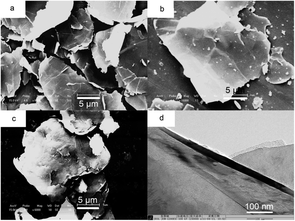 | ||
| Fig. 2 The micromorphologies of GNs and a-GNs, (a) SEM images of GNs, (b) magnified image of GNs, (c) SEM image of a-GNs, (d) TEM image of a-GNs. | ||
Fig. 3 shows the dispersion stability of NMP suspension with natural graphite flake, GNs and a-GNs. For all the three suspensions, 50 mg powder was dispersed into 10 mL NMP under sonication. After 8 h, the natural graphite flake (Fig. 3a) settled completely. For GNs (Fig. 3b), only a very small amount of GNs were left in the suspension. As for a-GNs, almost no settlement was observed (Fig. 3c). Both the FTIR and the stability results confirm that the acidified treatment remarkably improved the dispersibility of GNs in NMP suspension.
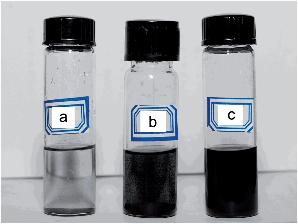 | ||
| Fig. 3 The dispersion stability (8 h) of natural flake graphite (a), GNs (b) and a-GNs (c) in NMP. | ||
Morphologies study of a-GNs@CuPc and a-GNs@CuPc/SPAEK composites
It is well-known that CuPc has a unique macrocyclic conjugated structure of phthalocyanine, and it can form the π–π conjugation with hexagonal carbon atom of a-GNs. Moreover, amino groups of CuPc can interact with carboxyl groups and hydroxyl groups on the a-GNs through hydrogen-bond interactions. These interactions ensure the coating of CuPc on the surface of a-GNs. Fig. 4 shows the TEM images and EDX spectra of a-GNs@CuPc with different mass ratios. Close examination of TEM image (Fig. 4a) reveals that CuPc nanoparticles were adsorbed on the surface of a-GNs when the mass ratio of CuPc to a-GNs was 1![[thin space (1/6-em)]](https://www.rsc.org/images/entities/char_2009.gif) :3. As the mass ratio of CuPc to a-GNs increased to 1:1 (Fig. 4b), the density of CuPc increased and almost no free space of a-GNs was left. This variation can also been observed in EDX spectra of a-GNs@CuPc (Fig. 4c and d). The EDX spectra show that percentage of copper (in copper phthalocyanine) in different a-GNs@CuPc is 0.57 and 1.04%, respectively. It is noteworthy that the percentage of copper increased only twice with the mass ratio of CuPc to a-GNs increased from 1:3 to 1:1 from EDX spectra. And this illustrates that only a part of CuPc was absorbed on the surface of a-GNs, but the others existed in solution.
:3. As the mass ratio of CuPc to a-GNs increased to 1:1 (Fig. 4b), the density of CuPc increased and almost no free space of a-GNs was left. This variation can also been observed in EDX spectra of a-GNs@CuPc (Fig. 4c and d). The EDX spectra show that percentage of copper (in copper phthalocyanine) in different a-GNs@CuPc is 0.57 and 1.04%, respectively. It is noteworthy that the percentage of copper increased only twice with the mass ratio of CuPc to a-GNs increased from 1:3 to 1:1 from EDX spectra. And this illustrates that only a part of CuPc was absorbed on the surface of a-GNs, but the others existed in solution.
 | ||
| Fig. 4 TEM images and EDX spectra of a-GNs@CuPc, (a and c) ma-GNs:mCuPc = 3:1, (b and d) ma-GNs:mCuPc = 1:1. | ||
Fig. 5 shows the SEM images of a-GNs/SPAEK and a-GNs@CuPc/SPAEK composites. All SEM images show the co-existence of both smooth regions and protruding regions. The smooth regions are the polymer matrix and the protruding gray regions are the fillers. Fig. 5a and c have same amount of a-GNs, but later image shows two regions of even filler and polymer matrix. With more a-GNs (Fig. 5b and d), the protruding gray regions expanded, while the smooth regions contracted. Compared with Fig. 5b, the protruding gray regions in Fig. 5d seemed more even.
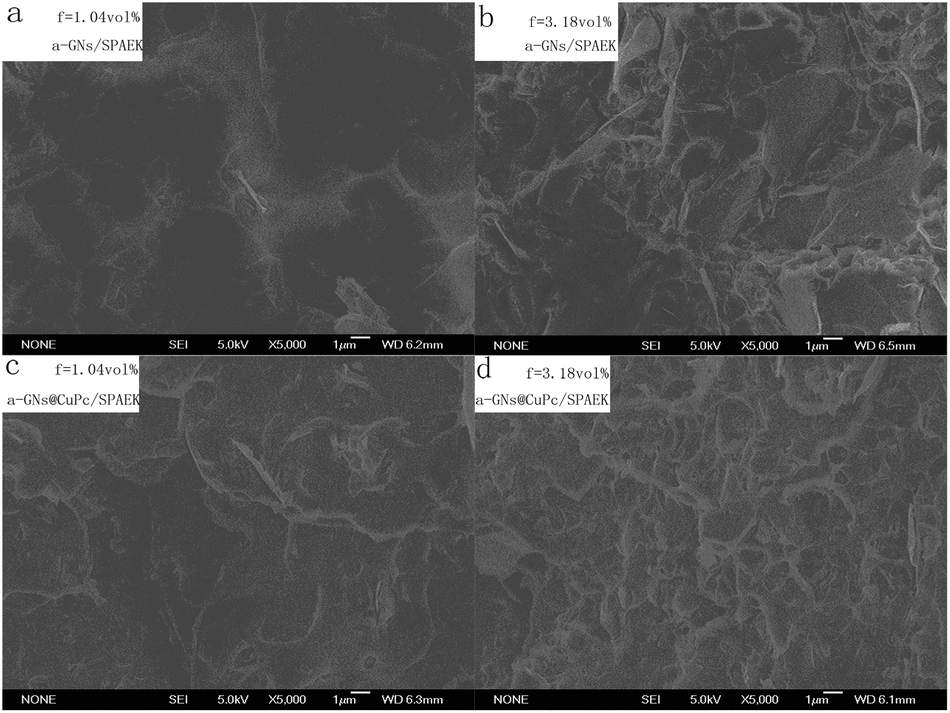 | ||
| Fig. 5 SEM images of fractured cross-section a-GNs/SPAEK and a-GNs@CuPc/SPAEK (ma-GNs:mCuPc = 3:1) composites with fa-GNs = 1.04 vol% and 3.18 vol%. | ||
To further investigate the dispersion of a-GNs in composites, SEM inverse images of a-GNs@CuPc/SPAEK a-GNs@CuPc/SPAEK (ma-GNs:mCuPc = 3:1) composites with fa-GNs = 3.18 vol% were shown in Fig. 6. It can be observed more obviously that the dispersion and distribution of a-GNs in a-GNs@CuPc/SPAEK is better than in a-GNs/SPAEK composite. This further confirmed that the CuPc coating on the surface of a-GNs effectively improves the dispersibility of a-GNs in the polymer matrix, which is attributed to the strong interaction between the amino groups of CuPc and the sulfonic acid group of polymer SPAEK.
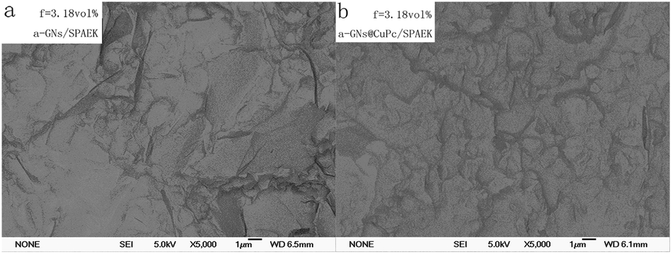 | ||
| Fig. 6 SEM inverse images of a-GNs@CuPc/SPAEK a-GNs@CuPc/SPAEK (ma-GNs:mCuPc = 3:1) composites with fa-GNs = 3.18 vol%. | ||
Dielectric properties of a-GNs/SPAEK and a-GNs@CuPc/SPAEK composites
Fig. 7 shows the frequency dependency of the dielectric constant of a-GNs/SPAEK with different filler loadings at room temperature. a-GNs/SPAEK composites show a relatively high dielectric constant at 100 Hz. At fa-GNs = 5.5 vol%, the dielectric constant of the composite is above 4000 at 100 Hz. However, the dielectric constants of a-GNs/SPAEK depend significantly on the frequency. As shown in Fig. 7, the dielectric constants of the composites decrease with increasing frequency. This phenomenon can be explained by the polarization mechanism of a heterogeneous material system. The Maxwell–Wagner effect indicates that the electric charge of a composite will accumulate at the interface because of the different conductivities of each component in an alternating electric field.31,32 For a-GNs/SPAEK, a-GNs have a large surface area, which ensures a large two-phase interface area between a-GNs and SPAEK in a-GNs/SPAEK and strong interfacial polarization effect. As frequency increases, the rate change of electric charge gradually falls behind the change of frequency. Meanwhile, the interfacial polarization extent was too weak to affect the dielectric properties of a-GNs/SPAEK. At fa-GNs = 5.5 vol%, the dielectric constant of a-GNs/SPAEK is over 100 at 1 MHz, which indicates that a-GNs/SPAEK can maintain a high dielectric constant even at a high frequency. In addition, dielectric constants of a-GNs/SPAEK composites decrease rapidly at higher frequencies when the content of a-GNs is above 3.18 vol% (Fig. 7). According to percolation theory,33,34 the percolation threshold of a-GNs/SPAEK was calculated to be fa-GNs = 3.18 vol%, where dielectric constant of the composite is 135, which is 22 times higher than that of SPAEK.35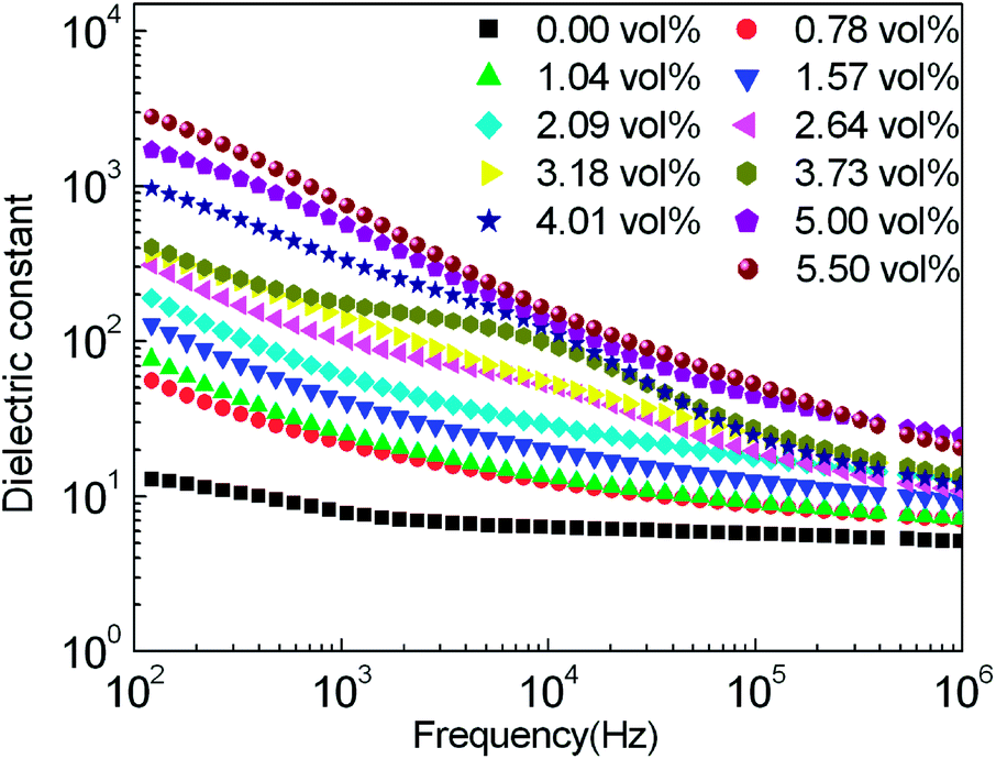 | ||
| Fig. 7 Dependence of dielectric constant on frequency for a-GNs/SPAEK composites at fa-GNs = 0–5.5 vol% at room temperature. | ||
Continuous conductive paths could lead to degradation in the dielectric properties, including an increase in dielectric loss and a decrease in dielectric strength. In order to prevent the conductive filler a-GNs from aggregating and contacting the matrix directly, CuPc is coated on the surface of a-GNs and a-GNs@CuPc was used as the filler in the SPAEK matrix to obtain the a-GNs@CuPc/SPAEK composites. The content of CuPc was adjusted to observe its effect on the dielectric properties of a-GNs@CuPc/SPAEK, while maintaining a 3:1 ratio of ma-GNs:mCuPc. The dielectric properties and conductivity of a-GNs@CuPc/SPAEK with different amounts of filler a-GNs@CuPc were investigated as shown in Fig. 8. Fig. 8a shows the dielectric constant of a-GNs@CuPc/SPAEK as a function of frequency. Under identical test conditions, the dielectric constant increases gradually with increase loading level of the a-GNs@CuPc in the composites. It is mainly due to conductivity increases of percolative composite (Fig. 8c). It also can be seen that the dielectric constant of the composites are closely related with the frequency, which decreases with increasing frequency for all the a-GNs@CuPc/SPAEK composites. This dependence is significantly enhanced when the content of the a-GNs@CuPc is 4.01 vol%, the dielectric constant of a-GNs@CuPc/SPAEK decreased rapidly with increasing frequency. These results indicate that more a-GNs@CuPc dipoles and charge carriers within the composites fail to keep up with the electric field of the increasing frequency. Additionally, compared to a-GNs/SPAEK, the dielectric constant of a-GNs@CuPc/SPAEK composites depends less on frequency. This can be explained by the polarization mechanism of a ternary composite. The a-GNs@CuPc/SPAEK composite has relatively weak interfacial polarization because of introduction of CuPc, resulting in a reduced frequency dependence on the dielectric constant of the composites. At high frequencies, interfacial polarization is weak between fillers and matrix, where the orientation polarization and displacement polarization of the material play a major role. Therefore, the CuPc coating gives a-GNs@CuPc/SPAEK a higher dielectric constant.
 | ||
| Fig. 8 Dependence of dielectric constant (a), dielectric loss (b) and conductivity (c) on frequency for the a-GNs@CuPc/SPAEK (ma-GNs:mCuPc = 3:1) composites. | ||
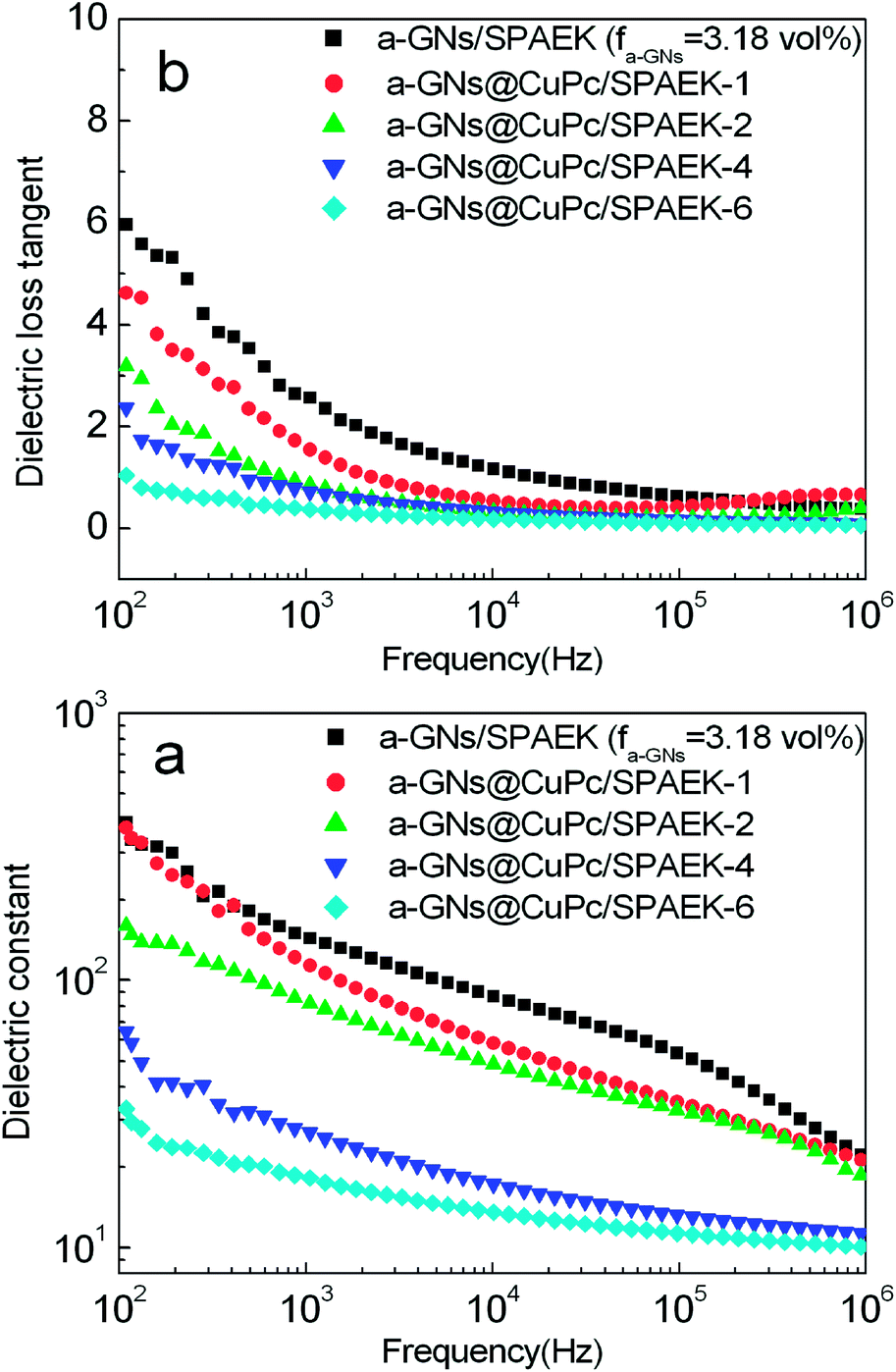
From Fig 8b, it can be observed that the dielectric loss tangents of a-GNs@CuPc/SPAEK composites increase slowly with increasing filler content below 3.18 vol%, whereas it decrease with increasing frequency. The dielectric loss tangents increased sharply to 10 at 100 Hz when the a-GNs@CuPc content is 4.01 vol%. It also can be explained that composite with 4.01 vol% filler has a higher conductivity (Fig. 8c). In addition, the a-GNs/SPAEK composites show larger dielectric loss tangents than a-GNs@CuPc/SPAEK for the same loading level and frequency.35For example, for fa-GNs = 3.18 vol% and at 1 kHz, the dielectric loss tangent of a-GNs@CuPc/SPAEK is only 0.4, compared to a-GNs/SPAEK composite with 2.4. For fa-GNs = 4.01 vol% and at 1 kHz, the dielectric loss tangent of a-GNs/SPAEK is 11.5, while it is only 2.1 for a-GNs@CuPc/SPAEK composites. It is worth noting that the dielectric constant of the a-GNs/SPAEK composite is 114 at 10 kHz and the dielectric loss is 3.18 at fa-GNs = 4.01 vol%, while the dielectric constant of a-GNs@CuPc/SPAEK is up to 200 at 10 kHz and the dielectric loss tangent is only 1.00. The significant decrease of dielectric loss for a-GNs@CuPc/SPAEK can be explained by the following reasons. The coating of CuPc on a-GNs ensures a better dispersion of filler a-GNs@CuPc into the matrix of SPAEK. On the other hand, the electric properties of fillers have a significant effect on the migration and accumulation of the charge carriers at interfaces between the fillers and the matrix, which contributes to the dielectric properties of the final composites.36 CuPc coating acts as an electric barrier, which serves as the insulating interface against direct contact between the adjacent conductive a-GNs and effectively suppresses the mobility of the free charge carriers.37 Therefore, the a-GNs@CuPc/SPAEK composites exhibit remarkably reduced dielectric loss compared to a-GNs/SPAEK.
In order to further investigate the influence of CuPc on the dielectric properties of the composites, the mass ratio of CuPc to a-GNs was adjusted. A series of a-GNs@CuPc/SPAEK composites were prepared following the same procedure, namely a-GNs@CuPc/SPAEK-1 (ma-GNs:mCuPc = 6:1), a-GNs@CuPc/SPAEK-2 (ma-GNs:mCuPc = 3:1), a-GNs@CuPc/SPAEK-4 (ma-GNs:mCuPc = 3:2) and a-GNs@CuPc/SPAEK-6 (ma-GNs:mCuPc = 1:1). Fig. 9 shows the dielectric constant and dielectric loss of a-GNs@CuPc/SPAEK composites with different contents of CuPc at fa-GNs = 3.18 vol%. It can be seen that both the dielectric constants and the dielectric loss of the composites continuously decrease along with increasing CuPc content. This is because the CuPc coating stops the a-GNs from overlapping, thereby reducing the percolation current and the dielectric loss of the a-GNs@CuPc/SPAEK composites. Meanwhile, the CuPc coating layer blocks the electron transfer of the system to a certain extent, resulting in the reduction of the dielectric constant of a-GNs@CuPc/SPAEK composites.
 | ||
| Fig. 9 Dependence of dielectric constant (a) and dielectric loss (b) on frequency for a-GNs@CuPc/SPAEK composites when the fa-GNs = 3.18 vol% and ma-GNs:mCuPc = 6:1–6:6 at room temperature. | ||
Mechanical and thermal properties of composites
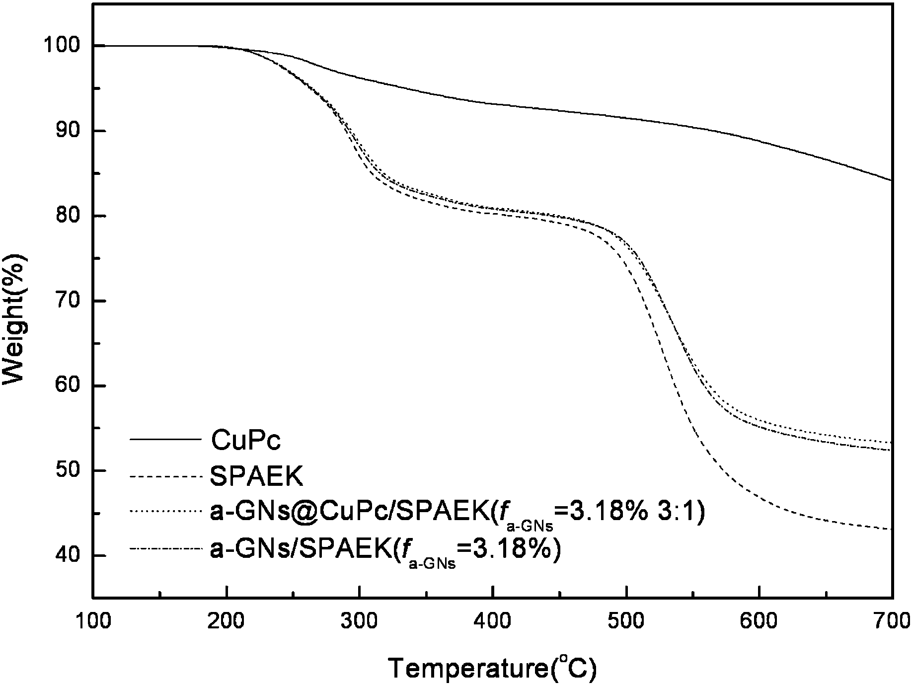
Fig. 10 shows the TGA of a-GNs/SPAEK and a-GNs@CuPc/SPAEK composites with fa-GNs = 3.18 vol% (ma-GNs:mCuPc = 3:1). The CuPc had a better thermal stability than SPAEK, with a 5% thermal decomposition temperature at 335 °C. Therefore, the thermal stabilities of the two composites depend significantly on the SPAEK matrix. Both the a-GNs/SPAEK and the a-GNs@CuPc/SPAEK composites show a 5% higher thermal decomposition temperature than SPAEK because of the strong interaction between the polymer matrix and the fillers.
 | ||
| Fig. 10 TGA curves of a-GNs/SPAEK and a-GNs@CuPc/SPAEK (ma-GNs:mCuPc = 3:1) composites. | ||
Table 1 lists the mechanical properties of a-GNs@CuPc/SPAEK composites at fa-GNs = 3.18 vol%. The reinforcement of a-GNs promotes the tensile strength and tensile modulus. Both a-GNs@CuPc/SPAEK and a-GNs/SPAEK exhibit better tensile properties than SPAEK. For a-GNs@CuPc/SPAEK, the tensile strength of 70.4 MPa, the modulus was 1.56 GPa and elongation breaking was 5.8 % at fa-GNs = 3.18 vol%, compared to 71.7 MPa, 1.91 GPa and 6.0% for a-GNs/SPAEK.
:mCuPc = 3:1) composites
Conclusions
Two series of novel dielectric percolative composites, ternary a-GNs@CuPc/SPAEK and binary a-GNs/SPAEK composites, were prepared using a simple solution blending technique. CuPc was coated on the surface of a-GNs, which effectively improved the dielectric properties of a-GNs@CuPc/SPAEK composites. This effect is attributed to two reasons: (1) the CuPc coating gives a better dispersion of a-GNs in the polymer matrix, and (2) the CuPc coating effectively suppress the mobility of free charge carriers. It was also found that the dielectric constant of the a-GNs@CuPc/SPAEK composite depended less on the frequency compared to that of a-GNs/SPAEK. a-GNs@CuPc/SPAEK can maintain a very high dielectric constant (200) even at a high frequency (10 kHz). In addition, the reinforcement of the filler a-GNs increases the tensile strength and tensile modulus of the composites.Acknowledgements
We gratefully acknowledged the financial support from the National Natural Scientific Foundation of China (No. 51173062 and 50803025).References
- Z. M. Dang, J. K. Yuan, J. W. Zha, T. Zhou, S. T. Li and G. H. Hu, Prog. Mater. Sci., 2012, 57, 660 CrossRef CAS PubMed.
- R. H. Baughman, A. A. Zakhidov and W. A. Heer, Science, 2002, 297, 787 CrossRef CAS PubMed.
- Q. M. Zhang, H. F. Li and M. Poh, Nature, 2002, 419, 284 CrossRef CAS PubMed.
- P. Brochu and Q. Pei, Macromol. Rapid Commun., 2010, 31, 10 CrossRef CAS PubMed.
- Z. M. Dang, S. H. Yao, J. K. Yuan and J. Bai, J. Phys. Chem. C, 2010, 114, 13204 CAS.
- T. P. Schuman and F. Dogan, ACS Appl. Mater. Interfaces, 2013, 5, 1917 Search PubMed.
- H. P. Xu, Z. M. Dang, M. J. Jiang, S. H. Yao and J. B. Bai, J. Mater. Chem., 2008, 18, 229 RSC.
- K. Hayashida and Y. Matsuoka, Carbon, 2013, 60, 506 CrossRef CAS PubMed.
- N. Ning, X. Bai, D. Yang, L. Zhang, Y. Lu, T. Nishi and M. Tian, RSC Adv., 2014, 4, 4543 RSC.
- P. Thomas, K. T. Varughese, K. Dwarakanath and K. B. R. Varma, Compos. Sci. Technol., 2010, 70, 539 CrossRef CAS PubMed.
- H. Wu, A. Gu, G. Liang and L. Yuan, J. Mater. Chem., 2011, 21, 14838 RSC.
- J. X. Lu, K. S. Moon and C. P. Wong, J. Mater. Chem., 2008, 18, 4821 RSC.
- J. Xu and C. P. Wong, Appl. Phys. Lett., 2005, 87, 082907 CrossRef PubMed.
- C. Yang, Y. H. Lin and C. W. Nan, Carbon, 2009, 47, 1096 CrossRef CAS PubMed.
- S. Stankovich, D. A. Dikin, G. H. B. Dommett, K. M. Kohlhass, E. J. Zimney, E. A. Stach, R. D. Piner, S. T. Nguyen and R. S. Ruoff, Nature, 2006, 442, 282 CrossRef CAS PubMed.
- G. H. Chen, D. J. Wu, W. G. Weng and W. L. Yan, Polym. Eng. Sci., 2001, 41, 2148 CAS.
- P. Sambyal, A. P. Singh, M. Verma, M. Farukh, B. P. Singh and S. K. Dhawan, RSC Adv., 2014, 4, 12614 RSC.
- A. Yasmin, J. J. Luo and I. M. Daniel, Compos. Sci. Technol., 2006, 66, 1179 Search PubMed.
- G. Chen, C. Wu, W. Weng, W. Dajun and W. Yan, Polymer, 2003, 44, 1781 CrossRef CAS.
- W. Zheng and S. W. Chung, Compos. Sci. Technol., 2003, 63, 225 CrossRef CAS.
- Q. Wang, W. Jiang, S. Guan and Y. Zhang, J. Inorg. Organomet. Polym., 2013, 23, 743 CrossRef CAS.
- V. Panwar and R. M. Mehra, Eur. Polym. J., 2008, 44, 2367 CrossRef CAS PubMed.
- M. J. McAllister, J. L. Li, D. H. Adamson, H. C. Schnieep, A. A. Abdala, J. Liu, M. Herrera-Alonso, D. L. Milius, R. Car, R. K. Prud’homme and I. A. Aksay, Chem. Mater., 2007, 19, 4396 CrossRef CAS.
- C. Min and D. M. Yu, Polym. Eng. Sci., 2010, 50, 1734 CAS.
- L. Gu, T. Wang, W. Zhang, G. Liang, A. Gu and L. Yuan, RSC Adv., 2013, 3, 7071 RSC.
- Y. H. Zhang, P. F. Huo, J. F. Wang, X. Liu and G. B. Wang, J. Mater. Chem. C, 2013, 1, 4035 RSC.
- B. I. Qi, S. Lee, W. D. Chen and G. J. Samuels, Adv. Mater., 2005, 17, 1777 CrossRef.
- X. Yang, Q. Wang, Z. Jiang and Y. Zhang, Polym. J., 2012, 44, 1042 CrossRef CAS.
- D. F. Ren, W. W. Wei, Z. H. Jiang and Y. H. Zhang, Polym.-Plast. Technol. Eng., 2012, 51, 1372 CrossRef CAS.
- J. R. Potts, D. R. Dreyer, C. W. Bielawski and R. S. Ruoff, Polymer, 2011, 52, 5 CrossRef CAS PubMed.
- F. He, S. T. Lau, H. Laiwa and J. T. Fan, Adv. Mater., 2009, 21, 710 CrossRef CAS.
- Z. M. Dang, H. P. Xu and H. Y. Wang, Appl. Phys. Lett., 2007, 90, 012901 CrossRef PubMed.
- C. W. Nan, Prog. Mater. Sci., 1993, 37, 1 CrossRef CAS.
- Z. M. Dang and Y. H. Lin, Adv. Mater., 2003, 15, 1625 CrossRef CAS.
- W. Jiang, Y. Liu, J. Wang, Q. Wang, Y. Zhang and S. Guan, J. Appl. Polym. Sci., 2014, 131 DOI:10.1002/app.40028.
- M. Arbatti, X. B. Shan and Z. Y. Cheng, Adv. Mater., 2007, 19, 1369 CrossRef CAS.
- Y. Shen, Y. H. Lin, M. Li and C. W. Nan, Adv. Mater., 2007, 19, 1418 CrossRef CAS.
| This journal is © The Royal Society of Chemistry 2014 |