
 Open Access Article
 This Open Access Article is licensed under a
 Creative Commons Attribution 3.0 Unported Licence
Current development, optimisation strategies and future perspectives for lead-free dielectric ceramics in high field and high energy density capacitors
Hareem Zubairi
 a,
Zhilun Lu
*b,
Yubo Zhu
c,
Ian M. Reaney
c and
Ge Wang
*a
a,
Zhilun Lu
*b,
Yubo Zhu
c,
Ian M. Reaney
c and
Ge Wang
*a
aDepartment of Materials, University of Manchester, Manchester, M13 9PL, UK. E-mail: ge.wang@manchester.ac.uk
bSchool of Chemical and Process Engineering, University of Leeds, Leeds, LS2 9JT, UK. E-mail: z.lu@leeds.ac.uk
cDepartment of Materials Science and Engineering, University of Sheffield, Sheffield, S1 3JD, UK
First published on 20th September 2024
Abstract
To meet the United Nations' sustainable development goal of affordable and clean energy, there has been a growing need for low-cost, green, and safe energy storage technologies. High-field and energy-density capacitors have gained substantial attention from academics and industry, particularly for power electronics, where they will play a key role in optimising the performance of management systems in electric vehicles. The key figure of merit, energy density (Wrec), for high-field applications has dramatically increased year-on-year from 2020 to 2024, as evidenced by over 250 papers, demonstrating ever larger Wrec values. This review briefly introduces the background and principles of high energy density ceramics, but its focus is to provide constructive and comprehensive insight into the evaluation of Wrec, Emax, ΔP, and η, and more importantly, the normalised metrics, Wrec/Emax and Wrec/ΔP in lead-free dielectric ceramics. We also present several optimisation strategies for materials modification and process innovation that have been recently proposed before providing perspectives for the further development of high-field and high-energy density capacitors.
 Hareem Zubairi | Hareem Zubairi is a Dean's doctoral scholarship funded (2023) PhD student at the Department of Materials, The University of Manchester. She obtained her BSc in Materials Engineering (2019) and MSc (2022) specialising in cold sintering of multiferroic ceramics from NED University, Pakistan. Hareem's dedicated research delves deep into the structure-composition-property relationship of lead-free ferroelectric, dielectric and piezoelectric ceramics. |
 Zhilun Lu | Dr Zhilun Lu is an Assistant Professor of Materials Science and Engineering at the University of Leeds. His research group focuses on the structure-composition-property relations of a broad spectrum of advanced functional materials, particularly ferroelectrics and thermoelectric. His expertise lies in employing impedance spectroscopy to probe electrical properties and neutron scattering to elucidate atomic structure and dynamics. He has led projects funded by the Royal Society and Royal Society of Chemistry, and published over 70 peer-reviewed papers, including in Nature Physics, garnering an H-index of 28. He is a frequent invited speaker at international conferences and serves on the editorial boards of several top materials science journals. He is also a peer reviewer for journals such as Nature Physics and Nature Communications. |
 Yubo Zhu | Yubo Zhu received his bachelor's degree from the University of Sheffield, UK, in 2022. He is currently a Year 2 PhD student in Prof. Ian M Reaney's group specifically on energy storage functional materials, his research focuses on sodium niobate systems. |
 Ian M. Reaney | Prof. Ian M. Reaney holds the Dyson Chair in Ceramics at the Department of Materials Science and Engineering, the University of Sheffield. He is a Fellow of the American and European Ceramic Society, the Royal Microscopical Society and the Institute of Materials, Minerals and Mining (IOM3). He has won numerous awards including the Verulam Medal (2017) in Ceramics from IOM3 and was recently elected to the World Academy of Ceramics. He is an Adjunct Professor at Pennsylvania State University (PSU) and European site director of the Centre for Dielectrics and Piezoelectrics in partnership with PSU and North Carolina State University. He published over 400 scientific papers with >27000 citations in total and H-index = 88 (Google Scholar). His research leadership in a wide range of ceramic disciplines has been recognised by >90 Invited/Plenary talks at International Conferences on topics such as Net-zero technology for ceramic manufacture, cold-sintering, microwave ceramics, bioceramics, relaxor-ferroelectrics, capacitors and piezoelectrics. |
 Ge Wang | Dr Ge Wang obtained a PhD (2016) from the University of Manchester. He worked as a Postdoctoral research associate at the University of Sheffield (2017-2022) and recently was awarded a Dame Kathleen Ollerenshaw Fellowship (2022) at the Department of Materials, The University of Manchester. His research is focused on the development (synthesis and characterisation) of high-performance functional ceramics, including electroceramics, solid-state electrolytes and high entropy perovskite oxides, using skillset ranging from crystal chemistry and crystallography to advanced processing of ceramics and prototype devices. He published 40+ peer-reviewed articles with a H-index of 24 and >3800 citations (Google Scholar). He is currently the deputy research lead for Nano and Functional Materials at the Department of Materials, a member of the early career editorial board for the Journal of Advanced Dielectric (JAD), and a professional member (MIMMM) of IOM3 and the Royal Society of Chemistry (MRSC). |
1. Introduction
Global energy demand has been increasing rapidly due to industrialisation, technological advancements, and the expanding economies of countries. According to a recent International Energy Agency (IEA) report,1 global energy consumption is expected to rise by 3.4% per year until 2026. To minimise global CO2 emissions, renewable, smart, and clean energy systems with high energy storage performance must be rapidly deployed to achieve the United Nation's sustainability goal.2 The energy density of electrostatic or dielectric capacitors is far smaller than in batteries and fuel cells.3–5 However, they possess the highest power density due to ultra-fast charge–discharge, as shown in the Ragone Plot (Fig. 1)6–8 and form an integral part of the power management of battery systems.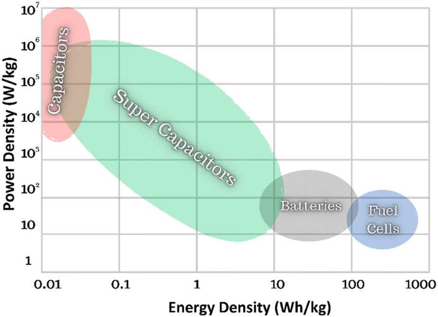 | ||
| Fig. 1 Power density vs. energy density (Ragone Plot) for different energy storage technologies. | ||
BaTiO3-based multilayer ceramic capacitors are commonly employed as filters and de-couplers in the consumer electronics industry, with a market valued at USD ∼ 3 billion in 2023, with a 4.9% compound annual growth rate in the US market (2024–2032).7 Ceramic dielectrics are popular due to their temperature stability (e.g. X7R MLCCs),9 fast charge–discharge speed (ms or ns), strong mechanical and fatigue resistance, and low manufacturing costs compared to polymer dielectrics.10 However, BaTiO3-based dielectrics break down at relatively low fields (<350 kV cm−1), limiting their energy density, and above 130 °C their permittivity declines markedly.10 Developing next-generation dielectric ceramics with higher energy density for high-field/voltage and high temperature (>200 °C) capacitor applications has therefore drawn increasing interest, particularly for power electronics in the automotive sector.
Lead (Pb) based dielectric ceramics, such as La-doped Pb (Zr, Ti)O3,11,12 have been used in pulsed capacitor applications for a number of years due to their exceptional power density and efficiency. However, researchers have been favouring Pb-free alternatives in the past decade due to legislation that restricts the use of Pb in consumer electronics. Fig. 2(a) illustrates the increase in publications on lead-free high-energy density ceramics from 2015 (∼50 papers) to 2023 (∼500 papers). Bulk ceramics based on BaTiO3(BT), Na0.5Bi0.5TiO3 (NBT), BiFeO3 (BF), AgNbO3 (AN) and NaNbO3(NN)-based ceramics, account for 80% of the publications, with multilayer ceramic capacitors (MLCCs) 8% and ceramic thin films 12%.
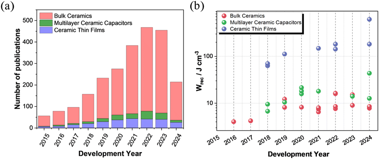 | ||
| Fig. 2 (a) Number of publications, Web of Science (keywords of high energy density ceramics, multilayer ceramic capacitors, and ceramic thin films, excluding glass, polymer, and composite). (b) Development of Wrec in bulk ceramics, ceramic multilayers, and ceramic thin films for energy storage applications from 2015 to 2024. | ||
The highest energy densities reported in the past 10 years for Pb-free bulk ceramics, MLCCs, and ceramic thin films are 16.3 J cm−3, 43.5 J cm−3, and 182 J cm−3, respectively. These values are achieved with approximate thicknesses of 50–150 μm for bulk ceramics, 5–20 μm for MLCCs, and 0.1–0.6 μm for ceramic thin films, and electrode areas typically ranging from 0.075 to 0.12 cm2. Bulk ceramics and MLCCs are prepared by solid-state sintering, with energy density influenced by factors such as electrode area and thickness. In contrast, ceramic thin films are formed using different techniques, where factors like substrate choice (strain), electrode area and thickness play a crucial role. However, further research in Pb-free dielectric ceramics is still required to offer high energy density (Wrec > 20 J cm−3) with efficiency (η > 90%), wide frequency range (1–1000 Hz), large temperature range (−50 to 250 °C), low dielectric loss (tan![[thin space (1/6-em)]](https://www.rsc.org/images/entities/char_2009.gif) δ < 2.5%), fast charge–discharge time (τ0.9 < 100 ns), co-fire compatibility with cost-effective internal electrodes and greater volumetric efficiency.
δ < 2.5%), fast charge–discharge time (τ0.9 < 100 ns), co-fire compatibility with cost-effective internal electrodes and greater volumetric efficiency.
In the realm of energy storage capacitors, many companies such as Skelton Technologies, TDK, Taiyo Yuden, Panasonic Corporations, Maxwell Technologies (now part of Tesla, Inc.), Kyocera Corporation, Murata Manufacturing Co. Ltd, Knowles Capacitors, and Ioxus, offer bulk ceramics and MLCCs tailored to specific applications. For instance, Knowles Precision Devices manufactures a wide selection of MLCCs, including AEC-Q200, Tandem and Open Mode, X8R and EMI filters, to meet the needs of electric and hybrid electric vehicle systems with a maximum voltage rating of 1 kV.13 Ceramic capacitor technology is expected to advance further with the MLCC market forecast to reach ∼USD 16.77 billion by 2030.14 High energy density and high voltage capacitors will be used in many applications15 as shown in Fig. 3, including but not limited to power electronics in electrical transportation, electronics, aerospace, pulse power applications and solar plants due to their high voltage tolerance, low loss, greater temperature and frequency stability and volumetric efficiency.9
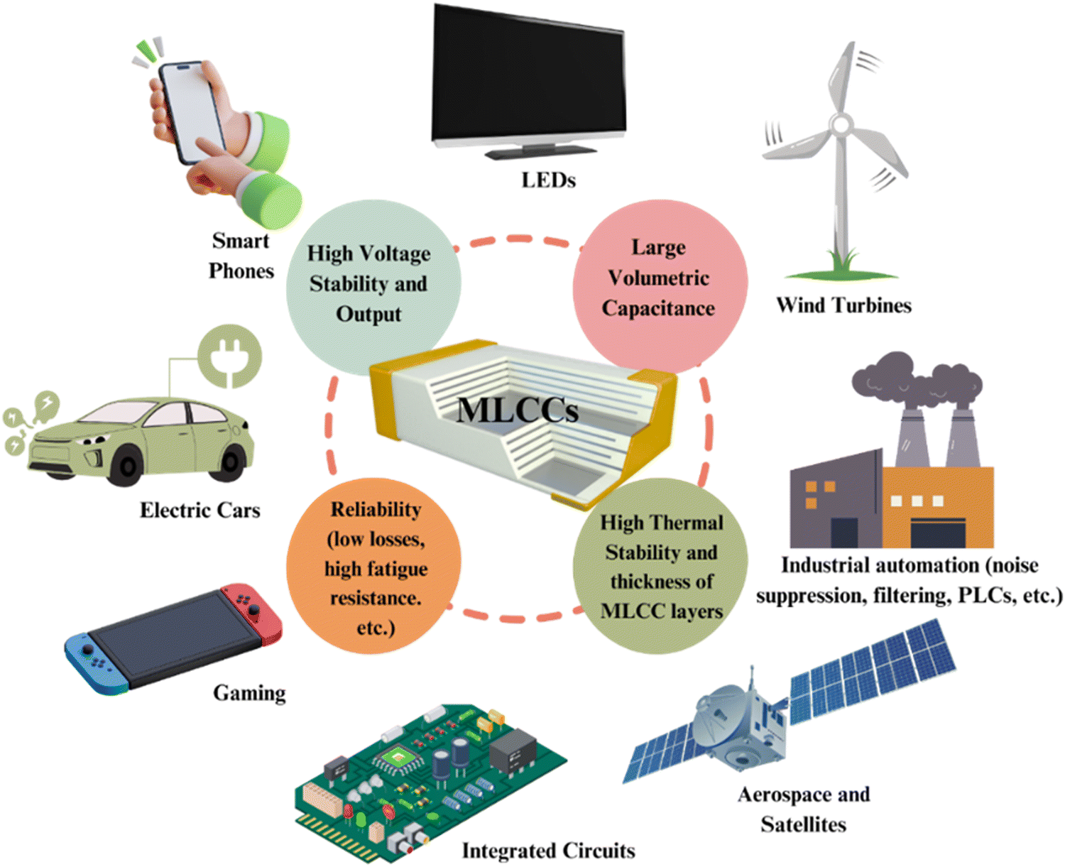 | ||
| Fig. 3 Schematic diagram of MLCCs with key properties in developing the high energy performance and their different applications. | ||
2. Principles of energy storage performance in lead-free dielectric ceramics
Understanding the principles of energy storage performance is crucial for designing and optimising materials for specific applications. The chapter covers three main topics: energy storage density evaluation, polarisation, and dielectric breakdown strength.2.1. Energy density evaluation of dielectric ceramics
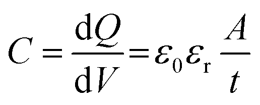
The typical representation of a capacitor consists of two parallel electrodes with a dielectric between them, as shown in Fig. 4(a and b). In dielectric capacitors, an external electric field is applied to induce polarisation in the dielectric, allowing for the storage of electrical energy (Fig. 4a). When the electric field is removed, the capacitor releases the stored energy, and the dipoles return to their initial state (Fig. 4b). This ability to store and release energy rapidly makes electrostatic capacitors suitable for applications requiring high power density (PD) for applications requiring ultrafast charge–discharge (τ0.9) cycles.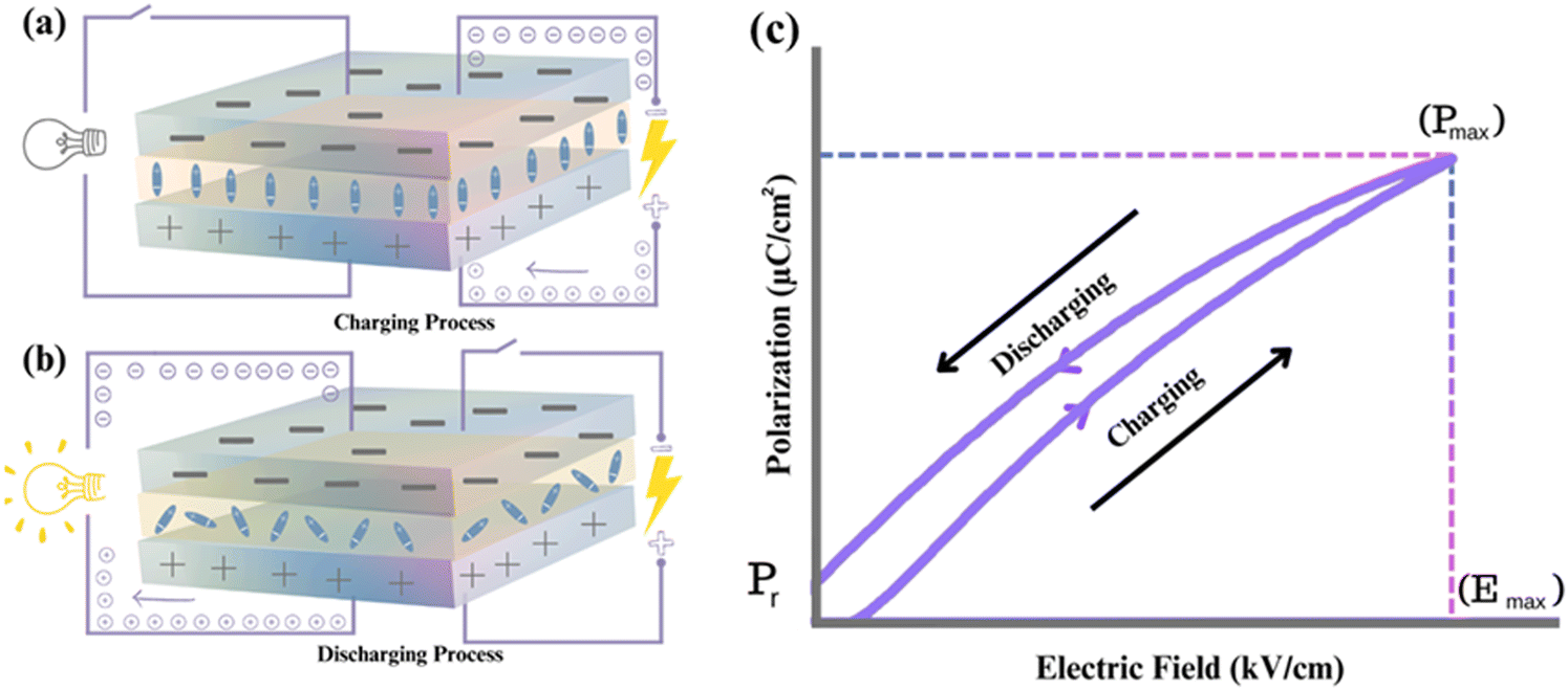 | ||
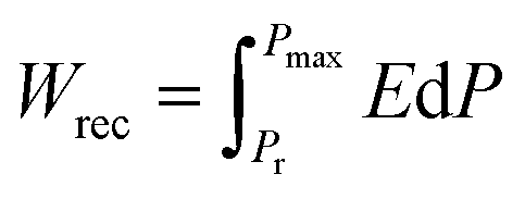
| Fig. 4 (a) Charging process (b) discharging process (c) P–E loop of evaluating energy storage performance of the dielectric capacitors. | ||
The energy storage of dielectric capacitors is related to capacitance (C), which is defined as the charge (dQ) induced by an external electric field (dV), as illustrated in Fig. 4c. The capacitance is calculated using the permittivity and geometry, as shown in eqn (1):
 | (1) |
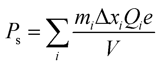
The energy storage density depends on εr and the applied electric field for all dielectrics. Due to energy dissipation via Joule heat loss, particularly in nonlinear dielectrics, the recoverable energy storage density (Wrec) is used to quantify the energy that can be recovered during the discharge cycle. Wrec is calculated as an integral of maximum polarisation (Pmax) and remnant polarisation (Pr), as shown in eqn (2):
 | (2) |
Achieving high energy density in dielectrics involves a combination of high Pmax, low Pr, high breakdown strength, and low dielectric loss. Understanding and controlling these nonlinear effects is essential in various applications, as they may limit the Wrec. Moreover, energy efficiency (η) is an important indicator for dielectric capacitors, alongside Wrec, particularly in practical applications. Energy efficiency is expressed by eqn (3):
 | (3) |
2.2. Polarisation
Polarisation–electric (P–E) loops, obtained from ferroelectric hysteresis measurements, demonstrate characteristics such as Pmax and Pr, coercive electric field (Ec), and Emax. These loops are typically obtained by measuring charge with a classical sawyer-tower circuit,16 which provides a preliminary estimate of energy storage performance. In this context, it's important to note that the electric displacement–electric field (D–E) loops may maybe more theoretically accurate to evaluate the energy storage performance of a ceramic capacitor since Wrec values are evaluated under the application of electric field. However, most of the studies assess their materials using P–E instead of D–E (based on ferroelectric hysteresis loops) because polarisation is closely related to the electric displacement based on the equation below:| D = ε0E + P | (4) |
Based on the form features of P–E loops shown in Fig. 5, dielectrics are categorised into four specific groups: ferroelectric (FE), antiferroelectric (AFE), relaxor (RFE), and linear dielectric (LD).17 FEs, as shown in Fig. 5(a), exhibit high Pmax and Pr, which collectively lead to nonlinear P–E loops, resulting in low Emax (less than 100 kV cm−1), Wrec and η, making them unsuitable for energy storage capacitor applications. AFEs, Fig. 5(b), exhibit dual hysteresis characteristics, with linear behaviour and FE loops positioned before and after, respectively, the critical switching field, making them desirable for energy storage applications. RFEs, obtained through the process of chemical doping, exhibit slim polarisation hysteresis loops as shown in Fig. 5(c), high Pmax and low Pr, ideal for high Wrec. LDs, in Fig. 5(d), on the other hand, typically exhibit low Pmax and Pr due to their low εr but can theoretically achieve high efficiency (η > 90%). The low energy storage density due to low Pmax and εr ensures a low volumetric efficiency for any device but linear dielectrics with higher values of Pmax and permittivity (>500) would constitute a breakthrough in dielectric technology.18
 | ||
| Fig. 5 Typical P–E loops for (a) ferroelectrics – FE (b) antiferroelectrics – AFE (c) relaxor ferroelectrics – RFE (d) linear dielectrics – LD. | ||
Delta polarisation, ΔP (Pmax − Pr), is crucial for assessing the energy storage capabilities of dielectric materials and depends on many factors such as grain size, microstructure, core–shell morphology, and electrode area. Moreover, minimising Pr is essential for efficient energy storage, allowing for effective energy release with minimal losses. These parameters can be optimised through material design, processing, and other strategies to enhance energy storage performance. Understanding and maximising ΔP are imperative for designing materials with favourable P–E loop characteristics, ultimately enhancing energy storage performance.18
It is also critical to understand the origin of polarisation for the lead-free dielectric/ferroelectric ceramics since some ultrahigh polarisation values (>50 uC cm−2, see Table 6 below) have been reported for dielectric thin films. It is impossible to get measured polarisation higher than spontaneous polarisation (Ps) which is a fixed value for a conventional ferroelectric (except the case for additional field-induced transition to produce higher Ps). Ps of ferroelectric ceramic systems can be calculated based on neutron diffraction, as proposed by Shimakawa et al.19 Then spontaneous polarisation caused by displacements can be calculated using Shima Kawa's model as follows:
 | (5) |
2.3. Dielectric breakdown strength
Dielectric breakdown (EBD) is an undesirable physical phenomenon where materials ionise, causing an electrical current to flow instantly through capacitors at excessive voltage. Emax is the maximum electric field a material can withstand before breakdown, while the maximum applied electric field is the highest applied field for effective energy storage at which the material breaks. Emax is influenced by internal factors (band gap, activation energy, electrical microstructure) and external factors (defects, porosity). The pulse electric field (Epulse) refers to short-duration, high-intensity fields that materials can endure in AC-pulsed conditions without breaking down. Most of the studies assess the energy storage performance of their materials using an Epulse of 1 to 20 Hz (based on P–E loops). Moreover, Yan's group proposed a new concept for assessing energy storage materials, termed recoverable energy storage intensity (ρ). This metric is defined as the Wrec per unit electric field difference (ΔE), where ΔE is the difference between the breakdown field and the starting electric field. This approach provides a refined method for evaluating the efficiency of energy storage materials under specific electric field conditions.21Several mechanisms have been proposed to explain dielectric capacitor failure, including thermal runaway, electromechanical breakdown, electric puncture, and partial discharge. A wider band gap (Eg) or activation energy (Ea) is considered a good indicator of higher Emax for dielectric materials. Chemical doping is an effective method for tailoring Emax by manipulating the electrical microstructure. Additionally, the thickness of ceramic specimens influences Emax during high-voltage electrical measurements (discussed later with respect to Fig. 19). Achieving high Emax is essential for high Wrec and reliable energy storage performance. Overall, a high-density, single-phase ceramic with high Emax, high resistivity and homogeneous electrical microstructure is ideal for delivering high-energy storage.
3. State-of-art lead-free dielectric ceramics for high energy density capacitors
State-of-the-art lead-free dielectric ceramics (bulk ceramics, multilayer ceramic capacitors, and ceramic thin films) are discussed along with how energy storage performance may be normalised to take into account the effect of thickness and electrode area.3.1. Bulk ceramics
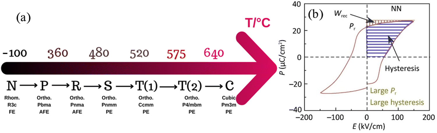 | ||
| Fig. 6 (a) Phase transition of NN ceramics as a function of temperature (b) PE Loop of NN.33 Reprinted (adapted) with permission from ref. 33 under the terms of the Creative Commons CC BY license, Elsevier. | ||
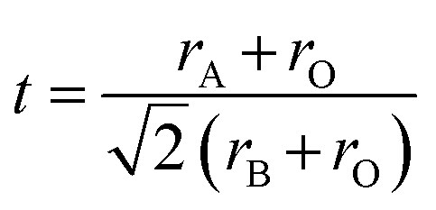
Recent studies on NN-based dielectric ceramics have been summarised in Table 1, which are primarily focused on (i) A-site chemical dopants (Na),34 (ii) B-site chemical dopants (Sr, Sn, Zr, Hf, W, Mn),35–37 (iii) A and B-site co-doping (Bi/Ta, Bi/Mg, Ca/Zr)38–40 and (iv) formation binary (NN–CaHfO3, CaTiO3 (CT), BT, BiScO3, SrTiO3 (ST), AN, and CaZrO3 (CZ))41–45 and ternary solid solution.22,33,35–37,40,45–54 NN-based systems have a dominant room temperature AFE structure with anti-parallel cation displacements normal to the long (b) axis.25,55 The AFE phase has a similar free energy to the FE Q phase and transforms irreversibly to the latter on the application of an electric field.25 However, the AFE structure may be stabilised using dopants that decrease the Goldschmidt perovskite (general formula, ABO3) tolerance factor, t.56
 | (6) |
 | (7) |
| Composition | Wrec (J cm−3) | η (%) | E (kV cm−1) | ΔP (μC cm−2) | τ0.9 (ns) | PD (MW cm−3) | εr (RT) | tanδ (RT) |
t (mm) | Ref. |
|---|---|---|---|---|---|---|---|---|---|---|
| 0.69NN–0.06BT–0.25Ca0.7La0.2TiO3 | 3.1 | 91 | 360 | 18 | — | 154 | 412 | 0.013 | 0.10 | 58 |
| 0.90(0.88NN–0.12Bi(Ni0.5Zr0.5)O3)–0.10CT | 5.1 | 83 | 580 | 12 | 35 | 75 | 383 | 0.010 | 0.10 | 59 |
| 0.85NN–0.15CZ | 5.4 | 82 | 680 | 32 | — | — | 545 | — | 0.10 | 48 |
| 0.8(0.92NN–0.08Bi (Mg0.5Ti0.5)O3)–0.2 CT | 5.7 | 86 | 475 | 31 | 28 | 48 | 373 | 0.003 | 0.10 | 31 |
| 0.96(0.8NN–0.2 ST)–0.04 Bi(Zn0.5Sn0.5)O3 | 5.8 | 92 | 573 | 11 | — | — | 712 | 0.009 | 0.10 | 60 |
| 0.85(0.92NN–0.08 Bi(Mg0.5Ti0.5)O3)–0.15 ST | 6.0 | 81 | 590 | 19 | 990 | 96 | 620 | 0.002 | 0.15 | 51 |
| 0.84NN–0.16CT | 6.6 | 93 | 520 | 15 | 700 | 350 | 730 | 0.009 | 0.10 | 42 |
| Na0.9Bi0.1Nb0.9Ta0.1O3 | 7.3 | 87 | 530 | 30 | 60 | 320 | 1450 | 0.002 | 0.15 | 38 |
| 0.75[0.90NN–0.10Bi(Mg0.5Ta0.5)O3]–0.25(Bi0.5Na0.5)0.7Sr0.3TiO3 | 8.0 | 90 | 800 | 23 | 32 | 49 | 620 | 0.005 | 0.15 | 61 |
| 0.88NNTa0.1–0.10ST–0.02La(Mg,Ti)O3 | 8.7 | 80 | 580 | 37 | — | — | 515 | 0.008 | 0.20 | 18 |
| 0.85 NN–0.15 Ca0.7Sm0.2TiO3 | 9.1 | 80 | 800 | 31 | 80 | 157 | 605 | 0.007 | 0.035 | 62 |
| (Na0.91Bi0.09)(Nb0.94Mg0.06)O3 | 10.9 | 83 | 820 | 30 | 19 | — | 920 | 0.002 | 0.06–0.08 | 63 |
| 0.76NN–0.24(Bi0.5N0.5) TiO3 | 12.2 | 69 | 620 | 59 | — | — | 1320 | — | 0.15 | 64 |
| 0.88 NN–0.12(Bi0.9Na0.1)(Fe0.8Ti0.2) O3 | 12.7 | 83 | 873 | 27 | 5000 | 200 | 650 | 0.002 | 0.05 | 65 |
| 0.88 NN–0.12(0.7BF–0.3BT) | 14.5 | 84 | 930 | 55 | 4500 | 233 | 780 | 0.002 | 0.05 | 66 |
| 0.12 NN–0.12(0.55BF–0.45 ST) | 16.2 | 82 | 970 | 61 | 4800 | 178 | 910 | 0.004 | 0.05 | 55 |
For example, t for the conventional lead-based AFE PbZrO3 is 0.964, lower than NN with a similar ΔX of 2.25 to ST and BT. Thus, NN's AFE may be stabilised by lowering its t value while holding ΔX constant.57 Recently, FE Q phase NN was stabilised in 0.9NN–0.1ST, which is further modified to a short-range relaxor 0.88NN–0.10ST–0.02La(Mg, Ti)O3 and then to an incipient/paraelectric for 0.88NaNb0.9Ta0.1O3–0.10ST–0.02La(Mg, Ti)O3 that exhibits quasi-linear dielectric (QLD) behaviour, where tanδ remained <0.01 between −143 to 290 °C (130 to 563 K) for NNTa0.10–10ST–2LMT (Fig. 7a). The polarisation increment, dP/dE, for QLD was found to be near constant (0.008 μC cm−1 kV−1) up to E > 500 kV cm−1, giving rise to excellent Wrec = 8.7 J cm−3 with η = 80% (Fig. 7b–d).18 To date, a 50 μm-thick 0.88NN–0.12(0.55BF–0.45ST) ceramic has been reported with the highest Wrec ∼16.2 J cm−3 with η ∼82%.
 | ||
| Fig. 7 (a) Temperature-coefficient of capacitance (TCC) values of NNTa0.10–10ST–2LMT across the temperature range from 800 K, (b) temperature-dependent M′′ spectroscopic plots for NNTa0.10–10ST–2LMT, (c) P–E loops of NNTa0.10–10ST–2LMT bulk ceramics, and (d) Calculated discharge energy density (U) and energy conversion efficiency (η) at various electric fields.18 Reprinted with permission from ref. 18, the John Wiley and Sons., under the terms of the Creative Commons CC BY license. | ||
The third strategy involves the formation of a solid solution with other compounds, such as (Sr0.7Bi0.2)HfO3 and Ca(Hf0.2Ti0.8)O379,80 to induce relaxor rather than AFE/FE switching behaviour. Recently, a significant milestone has been the successful development of AN-based MLCCs by several research groups,71,72 which have achieved high Wrec, principally due to a reduction in thickness of the dielectric layer in relaxor-based systems (third strategy). Fig. 8 shows a TEM image of Ag0.64Bi0.12NbO3 + 0.10 wt% MnO2 revealing lamellar domains, with Fig. 8b demonstrating the highest Wrec to date for AN-based materials.77 The energy storage properties of AN-based materials are summarised in Table 2.
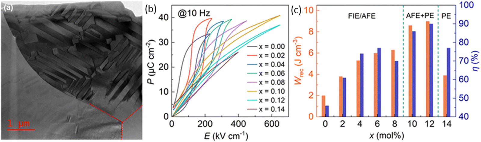 | ||
| Fig. 8 (a) Overview of bright-field TEM image displaying three grains of the Ag0.64Bi0.12NbO3 + 0.10 wt% MnO2 ceramic (b) unipolar P–E loops measured at 10 Hz, and (c) Wrec and η of AN–xBi ceramics at room temperature.77 Reproduced from ref. 77 with permission from the Royal Society of Chemistry. | ||
| Composition | Wrec (J cm−3) | η (%) | E (kV cm−1) | ΔP (μC cm−2) | τ0.9 (ns) | PD (MW cm−3) | εr (RT) | tanδ (RT) |
t (mm) | Ref. |
|---|---|---|---|---|---|---|---|---|---|---|
| Ag0.99Nd0.01Nb0.796Ta0.2O3 | 4.5 | 68 | 290 | 36 | — | — | 520 | 0.030 | — | 81 |
| 0.94 AN–0.06 CaHf0.2Ti0.8O3 + 0.2wt% Mn | 5.4 | 66 | 300 | 38 | — | — | 400 | 0.003 | — | 80 |
| Ag0.92Sr0.04Nb0.78Ta0.22O3 | 5.6 | 70 | 300 | 36 | 137 | 132 | 600 | 0.007 | — | 82 |
| Ag0.80Na0.20Nb0.80Ta0.20O3+ 0.1% MnO2 | 5.8 | 62 | 260 | 46 | 160 | — | 431 | 0.005 | 0.08 | 73 |
| AN@SiO2 + 0.10 wt% MnO2-doped + 4 mol% Bi2O3 and Sc2O3 | 5.9 | 71 | 322 | 42 | 160 | 273 | 813 | 0.001 | 0.06 | 83 |
| 0.945AN–0.055Sr0.7Bi0.2HfO3 + 1 mol% BaCu(B2O5) | 6.1 | 73 | 330 | 40 | — | — | 600 | 0.002 | 0.15 | 79 |
| Ag0.94La0.02Nb0.8Ta0.2O3 | 6.7 | 74 | 540 | 33 | — | — | 550 | — | 0.12 | 84 |
| Ag0.76La0.08NbO3 | 7.0 | 77 | 476 | 35 | — | — | 660 | 0.003 | 0.15 | 78 |
| Ag0.96Ce0.01Nb0.7Ta0.3O3 | 7.4 | 76 | 377 | 41 | 23 | 294 | 580 | — | 0.13 | 85 |
| 0.90AN–0.10Bi0.2Sr0.7TiO3 | 7.8 | 56 | 580 | 45 | 310 | — | 950 | 0.180 | 0.05 | 69 |
| Ag0.80Bi0.04Sr0.04NbO3 + 0.1 wt%MnO2 | 7.9 | 75 | 702 | 37 | — | — | 844 | 0.009 | 0.05 | 70 |
| Ag0.80Bi0.04Sr0.04Nb0.85Ta0.15O3 + 0.30 wt% MnO2 | 8.5 | 76 | 729 | 33 | 300 | — | 687 | 0.003 | 0.05 | 74 |
| Ag0.64Bi0.12NbO3 + 0.10 wt%MnO2 | 9.0 | 90 | 651 | 39 | — | — | 1100 | — | 0.05 | 77 |
As with AN, there are several strategies employed to optimise energy density in NBT-based ceramics. NBT is often combined with end members that have a large Eg, such as ST, Sr0·7Bi0·2TiO3 (SBT) and Ca0.7La0.2TiO3158 to form a relaxor phase (pseudo-cubic) with polar nano regions (PNRs). A high Wrec ∼10.3 J cm−3 with η ∼97%159 was reported by Zhou et al., in 0.85 (Bi0.5Na0.5)0.7Sr0.3TiO3 (BNST)–0.15 Bi(Mg1/3Ta2/3)O3 (BMT) in which Sr2+, Mg and Ta ions promote the formation of PNRs, due to their larger ionic radius leading to lattice strain which not only disrupts polar coupling (Fig. 9)160 but locally enhances polarisation.161 The low tolerance factor associated with NBT-based ceramics ensures that not only is their chemical and displacive cation disorder but also of the O−2 octahedral framework in which the amplitude and type of rotation (in-phase vs. antiphase) varies over a short range. Liu and co-authors162 utilised these strategies albeit expressed in different terms and reported 0.88 (0.75 NBT–0.25BT)–0.12NN ceramics with Wrec ∼15.2 J cm−3, η ∼91%, Emax ∼730 kV cm−1, τ0.9 ∼38 ns, temperature stability from 30–120 °C, frequency stability form 10–200 Hz and cyclic fatigue resistance (up to 107 cycles, with less than 1% changes).162 Energy density performance for a wide range of NBT-based compositions is summarised in Table 3.
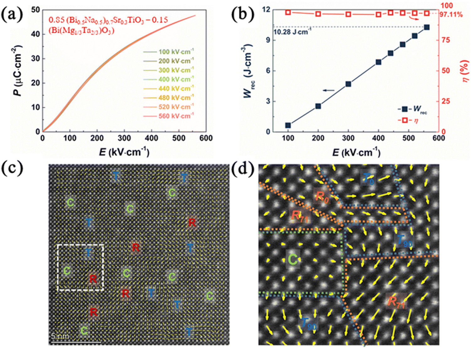 | ||
| Fig. 9 Properties of 0.85 (Bi0.5Na0.5)0.7Sr0.3TiO3–0.15 (Bi (Mg1/3Ta2/3) O3) ceramics (a) P–E Loops (b) Wrec and η values (c) HRDP STEM polarisation vector image along [100]c (d) enlarged image from the white frame.160 Reproduced from ref. 160 with permission from the Royal Society of Chemistry. | ||
| Composition | Wrec (J cm−3) | η (%) | E (kV cm−1) | ΔP (μC cm−2) | τ0.9 (ns) | PD (MW/cm3) | εr at RT | tan(δ) at RT | t (mm) | Ref. |
|---|---|---|---|---|---|---|---|---|---|---|
| 0.465NBT–0.035CaSnO3–0.5Sr0.7B0.2TiO3 | 4.0 | 80 | 415 | 38 | 116 | 107 | 2600 | 0.013 | 0.15 | 163 |
| 0.94Bi0.4867Sm0.0133Na0.4601Sm0.0133TiO3–0.06BaTiO3 | 4.4 | 84 | 230 | 42 | — | — | 990 | 0.035 | 0.11 | 21 |
| 0.75 NBT–0.25(Bi(Mg0.5Hf0.5Mg0.5Hf0.5)O3) | 4.6 | 75 | 310 | 21 | 110 | 39.1 | 430 | 0.023 | 0.12 | 164 |
| 0.62NBT–0.3Sr0.7Bi0.2TiO3–0.08BiMg2/3Nb1/3O3 | 7.5 | 92 | 470 | 48 | — | — | 1230 | 0.061 | 0.15 | 89 |
| 0.85(0.94NBT–0.06BT)–0.15 BiMg0.5Hf0.5O3 | 7.8 | 76 | 370 | 35 | — | — | 1600 | 0.230 | 0.20 | 90 |
| 0.85 Bi0.47Na0.47Ba0.06TiO3–0.15 Sr(Al0.5Ta0.5) O3 | 8.3 | 91 | 555 | 39 | 97 | — | 1460 | — | 0.05 | 165 |
| 0.90(Bi0.5Na0.5) 0.65 Sr0.35TiO3–0.10 Bi(Mg0.5Zr0.5) O3 | 8.5 | 86 | 522 | 59 | — | — | 1320 | 0.165 | 0.10 | 166 |
| 0.92(0.6NBT–0.4Sr0.7Bi0.2TiO3)–0.08 BMT | 8.6 | 93 | 565 | 45 | — | — | 1350 | 0.090 | 0.60 | 167 |
| NBT–Bi0.5K0.5TiO3–Sr (Sc0.5Nb0.5) O3 | 9.2 | 96 | 385 | 46 | 244 | — | 750 | 0.014 | 0.05 | 168 |
| 0.76(0.94NBT–0.06BT)–0.24 CaTi0.75Ta0.2O3 | 9.6 | 88 | 410 | 60 | — | 117 | 789 | 0.020 | 0.11 | 169 |
| 0.85 BNST–0.15 BMT | 10.3 | 97 | 420 | 54 | 1350 | — | 615 | 0.045 | 0.05 | 159 |
| 0.50(0.75NBT–0.25BT)–0.50 BaZrO3 | 13.6 | 91 | 660 | 63 | 35 | 313 | 455 | 0.070 | 0.08 | 170 |
| (Bi0.5Na0.5)(Ti0.33Fe0.33Nb0.33) O3 | 13.8 | 82 | 640 | 53 | 35 | 136 | 480 | 0.019 | 0.05 | 171 |
| 0.62(0.94NBT–0.06BT)–0.38 Ca0.7La0.2TiO3 | 15.1 | 82 | 640 | 61 | 32 | 212 | 710 | 0.001 | 0.12 | 158 |
| 0.88(0.75 NBT–0.25BT)–0.12 NN | 15.2 | 91 | 730 | 30 | 38 | — | 1896 | 0.003 | 0.05 | 162 |
δ, and low Wrec. Most research has adopted chemical dopants to overcome these issues which arise mainly due to the multiple and unstable valence of the Fe ions coupled with Bi volatilisation during processing.176 Therefore, BF-based dielectric ceramics are modified by doping at A- and/or B-site e.g. Nd,177 alloying with a third compound e.g. Bi(Zn2/3Nb1/3)178 or both, e.g. 0.61BF–0.33(Ba0.8Sr0.2) TiO3–0.06La (Mg2/3Nb1/3)O3 to improve electrical properties.179 The BF–BT solid solution was the first solid solution to exhibit large Wrec177,180,181 but the highest (16.3 J cm−3) with η ∼ 86% at Emax ∼690 kV cm−1 was reported for a 50 μm-thick 0.62Bi0.9La0.1FeO3 (BLF)–0.3Ba0.7Sr0.3TiO3 (BST)–0.08 K0.5Na0.5NbO3 (KNN) bulk ceramic,182 Fig. 10a. Other BF-based binary solid solutions include BF–K0.5Bi0.5TiO3 (BF–KBT)183 and BF–ST184 and are summarised in Table 4. Wang and co-authors183 reported a 0.5KBT–0.42BF–0.08Sm(Mg2/3Nb1/3)O3 (SMN) ceramics with the formation of lamellar nanodomains (Fig. 10b), giving Wrec ∼ 6.1 J cm−3 with η of 72% at E = 410 kV cm−1,183 along with good temperature stability from 25 to 150 °C (<15% variation). 0.35BF–0.65ST ceramics have also been reported with Wrec = 8.4 J cm−3 with η ∼ 90% at Emax = 750 kV cm−1 after a two-step sintering method (TSSM) which improved grain size, Emax, and Wrec, with less than 10% variation from 1–100 Hz and from 10–120 °C when compared to one-step sintering methods (OSSM), Fig. 10(c and d).184
 | ||
| Fig. 10 (a) Wrec and η values of 0.62 BLF–0.3 BST–0.08 KNN ceramics182 (b) TEM image of grain with lamellar nanodomains for 0.5 KBT–0.42 BF–0.08 SMN.183 SEM images for (c) OSSM and (d) TSSM 0.35BF–0.65ST ceramics.184 Reproduced with permission ref. 182 from the Royal Society of Chemistry. Reprinted with permission ref. 183 from Elsevier under the terms of the Creative Commons CC-BY license. Reprinted with permission from ref. 184, the John Wiley and Sons. | ||
| Composition | Wrec (J cm−3) | η (%) | E (kV cm−1) | ΔP (μC cm−2) | τ0.9 (ns) | PD (MW cm−3) | εr at RT | tan(δ) at RT | t (mm) | Ref. |
|---|---|---|---|---|---|---|---|---|---|---|
| 0.65BF–0.3 BT–0.05Bi (Zn2/3Nb1/3) O3 + 0.1 wt% Mn2O3 | 2.1 | 53 | 180 | 33 | 100 | — | 450 | 0.010 | — | 178 |
| 0.56BF–0.30BT–0.14AN + 5% mol CuO | 2.1 | 84 | 195 | 26 | — | — | 620 | 0.020 | 0.30 | 185 |
| 0.7(Bi0.97Nd0.03) [Fe0.95(Li0.5Nb0.5)0.05] O3–0.3BT + 0.1 wt% MnO2 | 3.2 | 74 | 290 | 28 | — | — | 500 | — | — | 186 |
| 0.61BF–0.33(Ba0.8Sr0.2)TiO3–0.06La(Mg2/3Nb1/3)O3 + 0.1 wt% MnO2 + 2 wt% BaCu(B2O5) | 3.4 | 59 | 230 | 27 | — | — | 380 | — | 0.30 | 187 |
| 0.5Bi1.02FeO3–0.37BT–0.13Bi(Zn2/3(Nb0.85Ta0.15)1/3)O3 | 4.8 | 80 | 410 | 25 | — | — | 125 | — | 0.08 | 188 |
| 0.88(0.67BF–0.33BT)–0.12Na0.73Bi0.09NbO3 | 5.6 | 84 | 410 | 14 | — | — | 700 | 0.090 | — | 189 |
| 0.5 KBT–0.42BF–0.08 SMN | 6.1 | 72 | 410 | 15 | — | — | 500 | 0.100 | 0.20 | 183 |
| 0.35BF–0.65ST | 7.5 | 93 | 626 | 33 | 166 | 280 | 430 | — | 0.04 | 184 |
| 0.85(0.7BF–0.3BT)–0.15NN | 8.2 | 70 | 275 | 65 | — | — | 1000 | — | 0.10 | 190,191 |
| 0.5BF–0.4 ST–0.03Nb–0.1BMN | 8.2 | 74 | 460 | 49 | — | — | 485 | — | 0.15 | 192 |
| 0.55BF–0.33BT–0.12NaTaO3 | 13.4 | 90 | 580 | 62 | 6 | 158 | 750 | — | 0.05 | 176 |
| 0.62 BLF–0.3 BST–0.08 NaNb0.85Ta0.15O3 | 15.9 | 88 | 680 | 57 | 6 | 192 | 590 | — | 0.05 | 193 |
| 0.62 BLF–0.3 BST–0.08 KNN | 16.3 | 86 | 690 | 64 | 6 | 181 | 550 | — | 0.05 | 182 |
One of the key factors to improve Emax and Wrec in BF-based dielectrics is the optimisation of the electrical microstructure, as proposed by Wang et al.181 For example, adding a third compound SMN into BF–KBT resulted in lower conductivity, higher Ea and electrical homogeneity,183 favouring high Emax as well as Wrec. In impedance complex plots such as Fig. 11(a), there are two M′′ (M′′ = 1/2C where C is capacitance) peaks at each temperature, indicating heterogeneous electrical microstructure (two-component) of the undoped BF-KBT ceramic. Instead, only one M’’ peak was identified for BF–KBT–0.08SMN ceramics, as shown in Fig. 11(b), whereas Fig. 11(c and d) shows the overlap of the Z′′ over M′′. Another example, 0.6BF–0.4ST–0.08BiMg2/3Nb1/3O3 (BMN)–0.01Nb ceramics, as reported by Lu and co-authors,192 also demonstrates that achieving electrical homogeneity even at the weak field with a highly resistive and large Ea is key to achieving high Emax as well as Wrec.
 | ||
| Fig. 11 Temperature-dependent M′′ spectroscopic plots for KBT–BF–xSMN ceramics183 (a) x = 0.00 and (b) x = 0.08. (c) Z′′ and M′′ spectroscopic plot for 0.6BF–0.4 ST ceramics at RT (d) Z′′ and M′′ spectroscopic plot for 0.6BF–0.4 ST–0.01Nb ceramics at 703 K.192 Reprinted (adapted) with permission from ref. 183 under the terms of the Creative Commons CC BY license, Elsevier. Reprinted (adapted) with permission from ref. 192 under the terms of the Creative Commons Attribution 3.0 Unsupported Licence, Royal Society of Chemistry. | ||
3.2. Multilayer ceramic capacitors (MLCCs)
MLCCs are composed of co-fired multiple layers of ceramic and internal electrodes. The fabrication involves slurry preparation, tape-casting, screen printing, lamination, co-sintering and termination, Fig. 12.194 By 2022, the market of ceramics MLCCs was ∼10.9 billion USD and is expected to be ∼16.77 billion by 2030.195 There are different demands for MLCCs as they are used in many different areas of electronics such as electric vehicles, medical implants, servers, robotics, and bypass capacitors.196,197 The leading companies for fabricating MLCCs include Murata Manufacturing and TDK Taiyo Yuden. The energy density performance of MLCCs is summarised in Table 5. | ||
| Fig. 12 Schematics of the fabrication process with its construction.194 Reproduced from ref. 194 with permission from the Royal Society of Chemistry. | ||
| Composition | Wrec (J cm−3) | η (%) | E (kV cm−1) | ΔP (μC cm−2) | τ0.9 (ns) | PD (MW cm−3) | εr at RT | t (μm) | Electrode | Ref. |
|---|---|---|---|---|---|---|---|---|---|---|
| 0.88BT–0.12 Bi (Li0.5Ta0.5) O3 | 4.1 | 95 | 466 | 25 | — | — | 30 | Pt | 198 | |
| Ag (Nb0.85Ta0.15) O3 + 0.25 wt.% MnO2 | 7.9 | 71 | 1020 | 44 | — | — | — | 15 | Pt | 199 |
| 0.67NN–0.18NBT–0.15Bi (Mg0.5Hf0.5) O3 | 12.7 | 88 | 1100 | 29 | 900 | 44 | 550 | 100 | 70 Ag/30Pd | 200 |
| 0.57BF–0.3BT–0.13 Bi (Li0.5Nb0.5) O3 | 13.8 | 81 | 950 | 54 | — | — | 10 | Pt | 201 | |
| Sm0.05Ag0.85Nb0.7Ta0.3O3 | 14.0 | 85 | 1450 | 20 | 900 | 103 | 440 | 10 | Pt | 71 |
| 0.87BT–0.13Bi [Zn2/3(Nb0.85Ta0.15)1/3] O3 | 14.1 | 70 | 1500 | 35 | — | — | 900 | 5 | Pt | 202 |
| 0.5BF–0.4 ST–0.03Nb–0.1BMN | 15.8 | 75 | 1000 | 50 | — | — | 510 | 8 | Pt | 192 |
| 0.62NBT–0.3Sr0.7Bi0.2TiO3–0.08BMN | 18.0 | 93 | 1013 | 54 | — | — | 1280 | 150 | Pt | 89 |
| 0.87BT–0.13Bi [Zn2/3(Nb0.85Ta0.15)1/3] O3 + SiO2 | 18.2 | 94 | 1755 | 35 | 450 | — | 920 | 10 | 60 Ag/40Pd | 203 |
| (Ba0.33Bi0.32Ca0.11Sm0.07Na0.07Sr0.1)(Ti0.63Fe0.32Zr0.05)O3 | 20.8 | 97 | 1094 | 49 | 11000 | — | 480 | 10 | 70Ag/30Pd | 204 |
| 〈111〉-textured 0.65NBT–0.35(Sr0.7Bi0.2) TiO3 | 21.5 | 80 | 1030 | 65 | — | — | 2000 | 20 | Pt | 205 |
| 0.88NaNb0.90Ta0.10O3–0.10ST–0.02La(Mg, Ti)O3 | 43.5 | 85 | 2800 | 35 | — | — | 515 | 6 | Pt | 18 |
Lead-free RFE-type MLCCs have been reported in the literature with promising energy storage performance and reliability, Table 5. For example, Lu and co-authors reported a 0.5BF–0.4 ST–0.03Nb–0.1BMN MLCC192 with high Wrec of 15.8 J cm−3 with η = 75.2% under Emax ∼1000 kV cm−1, as shown in Fig. 13. Nb5+ donor doping was used to enhance resistivity with a third end-member (BMN) promoting relaxor behaviour.
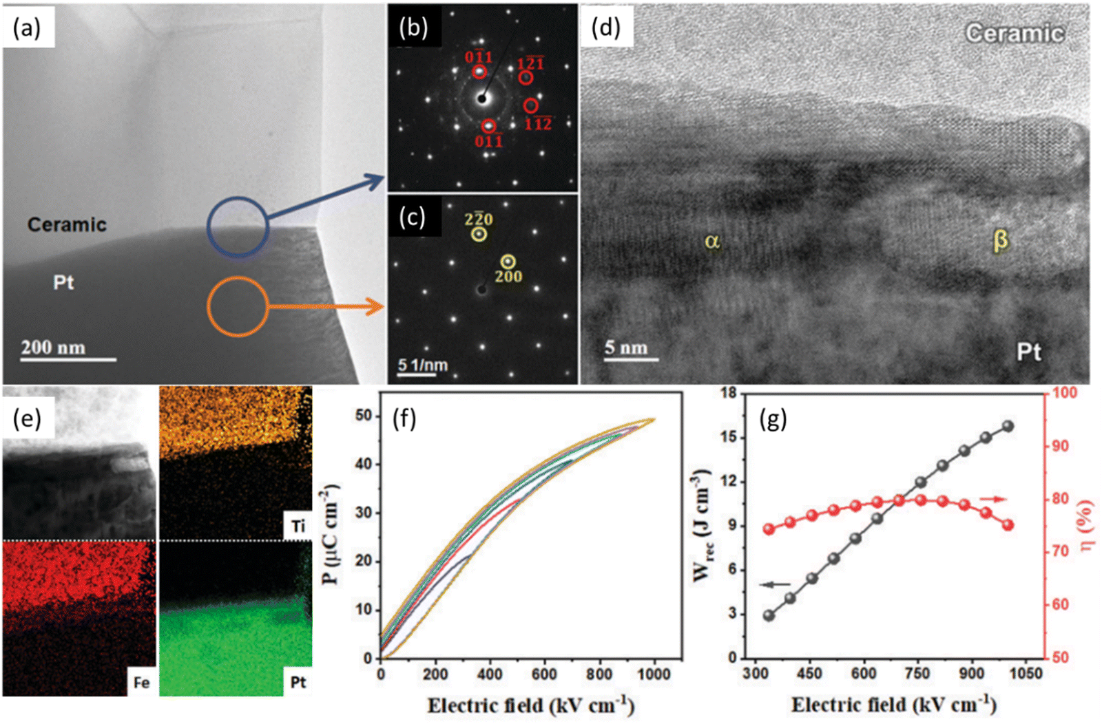 | ||
| Fig. 13 (a) TEM micrograph of BF–ST–Nb–0.1BMN/Pt interface. (b) SAD pattern highlighting BF–ST–Nb–0.1BMN reflections. (c) SAD pattern from Pt area in (a). (d) High-resolution TEM micrograph showing different phases at ceramic/Pt interface. (e) Bright-field STEM image and EDS elemental maps of ceramic/Pt interface. (f) Unipolar P–E loops. (g) Energy storage properties (Wrec and η) for BF–ST–Nb–0.1BMN multilayer.192 Reprinted (adapted) with permission from ref. 192 under the terms of the Creative Commons Attribution 3.0 Unsupported Licence, Royal Society of Chemistry. | ||
More recently, the energy storage performance (evaluated from P–E measurements) of the QLD MLCCs, 0.88NaNb0.90Ta0.10O3 (NNT)–0.10ST–0.02La(Mg, Ti)O3 (LMT), was Wrec = 43.5 (± 2.6) J cm−3 with η = 85 (± 3) %, Fig. 14, at least twice that of all reported MLCCs to date.18 The ultrahigh Wrec obtained in the QLD type MLCCs not only depends on its ability to withstand high Emax (associated with homogenous physical and electrical microstructure), low leakage conductivity and high activation energy) but also the QLD behaviour in which dP/dE is constant of 0.0013 (±0.0002) μC cm−1 kV−1 from low-field (750 kV cm−1) to high-field (2800 kV cm−1). The origin of near constant dP/dE still requires further investigation but is highly likely to be associated with weakly coupled polar displacements with random polarisation vectors (Fig. 14d).
 | ||
| Fig. 14 QLD type MLCCs performance. (a) Unipolar P–E curves of NNTa0.10–10ST–2LMT MLCCs up to the maximum field. (b) Polarisation maximum and increment as a function of electric field up to 280 MV m−1. (c) Energy storage performance up to the maximum field. (d) The [001]-oriented atomic resolution HADDF-STEM images for NNTa0.10–10ST–2LMT (QLD) with the projected polarisation angle. Individual arrows show B-site cation displacement vectors in individual unit cells with different vector angles.18 Reprinted with permission from ref. 18, the John Wiley and Sons., under the terms of the Creative Commons CC BY license. | ||
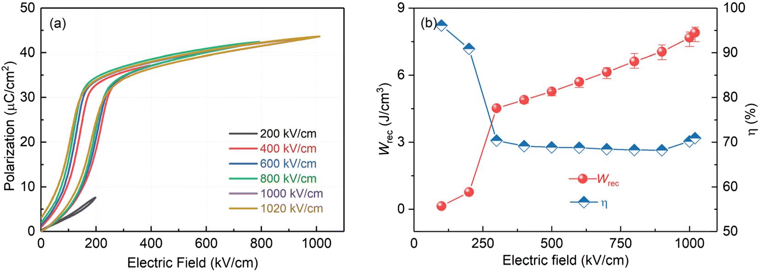
Additionally, NBT-based MLCCs have demonstrated significant improvements in energy storage performance. For instance, 〈111〉-textured NBT–Sr0.7Bi0.2TiO3 (NBT–SBT) multilayer ceramics (discussed in section 4.4) achieved a remarkable Wrec of 21.5 J cm−3 with η ∼80% at Emax ∼ 103 MV m−1. This enhancement in performance is attributed to the controlled grain orientation, which reduces the strain induced by the E and improves Emax.205 Priya and co-authors investigated AFE-type MLCCs with Ag(Nb0.85Ta0.15)O3 + 0.25 wt.% MnO2 (ANT + Mn) as the dielectric.81 The AFE-FE transition was observed around 250 kV cm−1, resulting in a decrease in η from over 95% to approximately 70% (Fig. 15). These MLCCs exhibited a Wrec of 7.9 J cm−3 with η measured at 71% at Emax ∼1020 kV cm−1, demonstrating lower performance compared to other lead-free REF-type MLCCs.
 | ||
| Fig. 15 Energy storage of ANT + Mn multilayer capacitors. (a) Unipolar P–E loops and (b) Wrec and η measured at different electric fields from 200 kV cm−1 to 1020 kV cm−1.81 Reproduced from ref. 81 with permission from the Royal Society of Chemistry. | ||
3.3. Ceramic thin films
Substantial progress in the development of lead-free thin films, e.g., BT, NBT and BF, has been achieved through various synthesis methods, such as sputtering, pulsed laser deposition and chemical solution deposition206–208 allowing precise control over composition and thickness.209–215 Although thin films may have applications in electrostatic energy storage devices for highly miniaturised electronics requiring high voltage and high temperature, the technology cannot compete on cost with powder-based MLCC fabrication technology.For dielectric thin films, both Emax (>2000 kV cm−1) and Wrec (>40 J cm−3) are significantly higher than bulk ceramic and MLCCs due to fewer defects and pores, as summarised in Table 6. Most research into lead-free ceramic thin films has focused on perovskite-type BT and BF-based compositions. High Wrec ∼112 J cm−3 with η ∼80%, along with good temperature stabilities between −100 to 150 °C, was reported in a 450 nm-thick 0.25BF–0.3BT–0.45 ST thin film at Emax ∼4900 kV cm−1, which the authors explained through the presence of a disordered crystal structure with mixed polymorphic nanodomains.209 Non-perovskite-type dielectric thin films have also been reported with promising energy storage performance. A 350 nm-thick Aurivillius-type Bi3.15Nd0.85Ti2.8Zr0.2O12 thin film was optimised to deliver a high ΔP ∼103 μC cm−2 and Wrec ∼124 J cm−3 with η ∼80% at Emax ∼3000 kV cm−1 ref. 207 with fatigue-resistant up to 109 charge/discharge cycles and a wide temperature range of −100 to 200 °C. The best electrostatic energy storage performance to date, Wrec ∼182 J cm−3 with η ∼78% at Emax ∼6200 kV cm−1, was reported in 2022 by Lin et al. in a pyrochlore-type dielectric thin film, Fig. 16(a and b).210 The authors proposed this huge response was due to the growth of a high-entropy stabilised Bi2Ti2O7-based dielectric film with the coexistence of multiple lattice distortions. The large Wrec was attributed to the large Emax (increased resistivity and breakdown properties) correlated with the presence of nano-crystalline grains and amorphous-like phases in the microstructure, as displayed in Fig. 16(c and d).
| Composition | Substrate | Wrec (J cm−3) | η (%) | E (kV cm−1) | ΔP (μC cm−2) | εr at RT | t (nm) | Ref. |
|---|---|---|---|---|---|---|---|---|
| BaZr0.35Ti0.65O3 | ITO layer | 40.6 | 69 | 4230 | 22 | 86 | 130 | 211 |
| Ag (Nb0.45Ta0.55)O3 | Si (100) | 46.4 | 80 | 3300 | 34 | 130 | 300 | 212 |
| 0.4BF–0.6ST | Nb: STO | 51.0 | 60 | 3600 | 40 | 225 | 500 | 213 |
| Ba (Zr0.35Ti0.65)O3 | LSMO + STO + F-Mica | 65.1 | 73 | 6150 | 28 | 141 | 130 | 214 |
| 0.88Ba0.55Sr0.45TiO3 –0.12BMN | Nb: STO | 86.0 | 73 | 5000 | 51 | 240 | 400 | 216 |
| Ba0.3Sr0.7Zr0.18Ti0.82O3 | Pt-coated Si | 89.4 | 65 | 6300 | 38 | 151 | 610 | 217 |
| Ba(Zr0.35Ti0.65)O3 | Si | 93.5 | 71 | 8500 | 30 | 57 | 415 | 218 |
| Ba0.95Sr0.05Zr0.2Ti0.8O3 | Pt/Ti/SiO2/Si | 102.0 | 87 | 6200 | 30 | 65 | 100 | 219 |
| 0.25BF–0.3BT–0.45 ST | (001)-oriented Nb: STO | 112.0 | 80 | 4900 | 57 | 250 | 450 | 209 |
| (Ba0.95, Sr0.05)(Zr0.2, Ti0.8)O3 | Pt (111)/Ti/(100)Si | 148.0 | 91 | 6600 | 49 | — | 300 | 220 |
| (Bi3.25La0.75)(Ti1.8Zr0.4Hf0.4Sn0.4)O12 | Pt (111)/Ti/SiO2/Si | 182.0 | 78 | 6200 | 55 | 80 | 620 | 210 |
 | ||
| Fig. 16 (a) Energy density and efficiency as functions of electric field up to breakdown strength. (b) Comparison of the energy density and efficiency of our films with representative dielectrics. (c) Low-magnification HAADF image of the ceramic thin film, showing the coexistence of nano-crystalline grains (numbered 1–8) and an amorphous-like phase (no. 9). (d) Nano-beam electron diffraction patterns of the nano-crystalline grains and amorphous-like phase labelled by 1–9 in (c).210 Reproduced from ref. 210 with permission from Springer Nature. | ||
However, it is important to note that the mechanisms underlying the high polarisation values observed in thin films have not been fully evaluated. There is an urgent need for further investigation to understand why these thin films exhibit such large polarisation responses, as this could significantly impact the future design and optimisation of high-performance dielectric materials.
3.4. Summary of state-of-the-art lead-free ceramics for high energy density capacitors
The development of lead-free dielectric ceramics for high-energy-density capacitors has seen significant progress over the past five years, as evidenced by the increasing number of publications (Fig. 2). The figure-of-merit (Wrec and η) of these lead-free candidates is either equivalent to or outperforms their lead-based counterparts, although we note that much less research and optimisation have been performed on lead-based systems. Class-II capacitors for consumer electronics rely on BT but it offers lower Wrec than competitor compositions.14,15,221–225 Instead, there has been an explosion of lead-free candidates based on AFEs (NN and AN) and FEs (NBT and BF). Several promising bulk ceramic compositions based on NN and AN have successfully transitioned into MLCCs using powder-based synthesis methods (tape-casting). This success highlights the potential for larger-scale manufacturing of new lead-free high-energy-density capacitors. Comparatively, the Wrec of ceramic thin films (t < 1 μm) surpasses that of bulk ceramics and MLCCs but this is attributed in the main to their higher breakdown strengths with Emax an order of magnitude greater than in MLCCs. | ||
| Fig. 17 Comparison between (a) Wrec vs. η (b) Wrec vs. Emax (c) Wrec and ΔP (d) Emax vs. ΔP in different bulk ceramics. | ||
 | ||
| Fig. 18 The comparison between (a) Emax and Wrec and (b) Wrec and η in terms of thickness. | ||
 | ||
| Fig. 19 Impact of thickness on (a) Emax (b) normalised Wa = Wrec/Emax and η in NN, AN, NBT, and BF-based ceramics (c) normalised Wa with η (d) normalised Wa with ΔP in bulk ceramics, MLCCs, and thin films. | ||
 | ||
| Fig. 20 The relationship between (a) electrode area and ΔP in NN, AN, NBT, and BF-based ceramics (b) normalised Wb and η in NN, AN, NBT, and BF-based ceramics (c) normalised Wb and η in bulk ceramics, MLCCs, and thin films (d) normalised Wb and Emax in bulk ceramics, MLCCs, and thin films. | ||
The electrode area information is commonly provided in recent studies on bulk ceramics, as it influences polarisation during electrical P–E measurements. However, this crucial parameter is often ignored or unreported in ceramic thin film and MLCC studies. The determination of the effective dielectric layer thickness in MLCCs and ceramic thin films commonly relies on direct measurements from SEM images. However, discrepancies may arise when estimating electrode areas, often leading to calculation errors in energy storage assessments. From this perspective, we propose that evaluating electrode area is equally important as ceramic thickness and is critical for electrical measurements to accurately assess energy storage.
4. Strategies for optimising energy storage performance
Achieving an optimal balance among various parameters is essential for improving energy storage. The enhancement of energy density typically compromises efficiency, and vice-versa. Recent studies underscore that securing a high Emax is critical, even at the expense of a reduced ΔP. As highlighted in the preceding summary, diminishing sample thickness can mitigate defects, thereby substantially enhancing Emax. To obtain ceramics with high density and fine grain size, numerous methodologies have been documented, including Repeated Rolling Processing (RRP),159,165,168 two-step sintering,184 and the incorporation of Bi-based constituents as sintering aids.55,64 Besides optimisation of density and microstructure, the following strategies are also crucial for improving energy storage.4.1. Optimisation of electrical properties
The substitution of NN in BF–BT bulk FEs has been shown to increase the band gap.30 Moreover, NN-based materials not only exhibit inherently superior Emax compared to other systems, as highlighted in the preceding summary, but their wide band gap has also shifted research focus towards reducing resistivity.29Incorporating manganese (Mn) into AN-, NN-, and BF-based material systems is a strategy widely adopted to enhance resistivity,68,69,117,187,226–228 and is especially crucial for BF-based materials due to their susceptibility to high leakage currents.229,230 Inspired by techniques employed in lead-based materials, manganese oxides function as electron traps to improve resistivity (as shown in Fig. 21(a) where Mn is doped in NN–SrSnO3)49 and as a grain-size refiner.231–233 Tantalum (Ta) has been reported as a promising dopant to enhance resistivity and activation energy in AN- and NN-based materials.38,84,153,198 Additionally, due to the refractory nature of Ta2O5, Ta can also reduce grain size, which is beneficial for achieving higher breakdown strength (Emax) (Fig. 21(b)).75
 | ||
| Fig. 21 (a) Nyquist-plot of the NN, NN–5SrSnO3, NN–5SrSnO3_0.1Mn, and NN–5 SrSnO3_1.0Mn samples.49 (b) The composition dependence of average grain size and Eb, the insets give the SEM micrographs of the AN and AN–Ta0.55 ceramics, respectively.77 Reprinted with permission ref. 49 from under the terms of the Creative Commons CC BY license, Springer Nature. Reprinted with permission from ref. 77, under the terms of the Creative Commons CC BY license, Springer Nature. | ||
Research on interfacial polarisation (Maxwell–Wagner polarisation caused by space charge in heterogeneous systems) restriction in NBT–BT ceramics,158 has shown that decreasing the resistivity difference between grains and grain boundaries achieves electrical homogeneity like those in BF-based systems.181,234 Impedance spectroscopy, a valuable method for evaluating the electrical homogeneity of materials, has been utilised in various energy storage dielectric materials, including BF-, NBT-, and NN-based ceramics.31,51,59,60,63,158,166,178,235 Impedance spectroscopy can demonstrate when the imaginary parts of impedance (Z′′) and electrical modulus (M′′) overlap, a signal for electrical homogeneity across ceramics. In conclusion, the synergistic enhancement of Eg, Ea, and the presence of a homogeneous electrical microstructure, play a pivotal role in boosting Emax.
4.2. Disruption of long-range polar order
Optimising factors such as high density, small grain size, and electrical properties are crucial, but another critical aspect is the disruption of the long-range polar order in the material matrices sometimes referred to as phase or domain engineering. This strategy attains a high η but reduces Pmax due to the onset of relaxor behaviour in which PNRs, rather than macrodomains minimise polarisation switching hysteresis, leading to slimmer P–E loops.Fig. 22 illustrates the common strategies used across various dielectric systems to disrupt long-range polar order, showing general trends rather than specific examples for each material. The disruption of long-range polar order, phase transitions, and domain structure discussed here are widely applicable across AN, NN, BF, and NBT systems, making such a generalised approach appropriate.
 | ||
| Fig. 22 Schematic microstructure and unipolar P–E loops (with the same internal electric between red, green, and blue) of different dielectrics for electrostatic energy storage (evaluated by the area of red, green and blue) (a) FE with macroscopic domains (dP/dE = 0) (b) RFE with multiple polar nanoregions (dP/dE → 0). (c) QLD behaviour with lattice distortions (dP/dE = constant, k).18 Reprinted with permission from ref. 18, the John Wiley and Sons., under the terms of the Creative Commons CC BY license. | ||
For AN- and NN-based AFE materials, doping or the introduction of solid solutions can lower the temperature onset of phase transitions such as M2, and M3 for AN-based and R and Q phase for NN-based.28,42,78,80,183,236,237 Simultaneously, dopants disrupt long-range antipolar order, resulting in smaller domains, leading to reduced Pr minimising electro strain and driving higher efficiency through slimmer loops associated with the field-induced FE phase. Using this approach, an ultrahigh Emax of ∼1450 kV cm−1 and an outstanding Wrec of about 14 J cm−3 with an η of approximately 85% were realised in Sm0.05Ag0.85Nb0.7Ta0.3O3 MLCCs.71
In BF- and BNT-based perovskites, the tilting of oxygen octahedra often impedes domain reorientation, as evidenced by the large coercive field (EC). By combining a FE component with significant structural distortion (δ) and a paraelectric (PE) component to create an RFE with a t close to 1, it is possible to achieve exceptionally high Wrec and high η simultaneously.161 Additionally, doping with ions of varying valence, electronegativity, and ionic radii may induce significant local lattice disorder, leading to the disruption of long-range polar order and the formation of PNRs, thereby substantially reducing Pr.182
4.3. High entropy enhancement
Since 2004, the concept of disordered multicomponent systems emerged, aiming to maximise configurational entropy and stabilise equimolar mixtures, leading to the development of high-entropy materials. Initially explored in metal alloys and nitride films, entropy stabilisation was later demonstrated in oxides in 2015, spurring the rapid development of high-entropy disordered ceramics. Highly disordered, multi-component systems benefit from high entropy, leading to preferred single-phase solid solutions, sluggish kinetics, lattice distortions, and superior properties. This versatility enables the enhancement of properties by tailoring the compositions of the ceramics in the field of high-energy dielectric ceramic capacitors.Derived from the Gibbs free energy, the relationship between the atomic fraction of elements and entropy of mixing is shown below, where ΔSmix is the entropy of mixing, R is the gas constant, and N is the total number of elements, yielding the results for single phase materials usually.238
|
ΔSmix = RlnN
| (8) |
Smix reaches a maximum when all elements are present in an equiatomic 5-cation system, the maximum Smix value that can be achieved is 1.61 R. As per empirical classification, based on its configurational entropy introduced by Murty et al.,239 https://onlinelibrary.wiley.com/doi/full/10.1002/adma.201806236-adma201806236-bib-0012 materials with Smix ≥ 1.5 R can be classified as “high entropy”, materials with 1.5 R > Smix ≥ 1 R as “medium entropy” and materials with Smix < 1 R as “low entropy” systems. When Smix ≥ 1.5 R, a single phase is often attained, as the magnitude of TΔSmix becomes significant enough to surpass enthalpy, ΔHmix, which is dependent on the free energy of the system (ΔGmix) particularly at elevated temperatures (T), as shown in eqn (9). This underscores the importance of high temperatures in facilitating the formation of high or medium entropy (single-phase) systems; however, many of these systems are deemed metastable at room temperature.238
| ΔGmix = ΔHmix + TΔSmix | (9) |
In bulk materials, notable successes using a ‘high-entropy’ approach are exemplified in KNN- and NBT-based ceramics, and recently a BT-based MLCC204 which exhibits relaxor behaviour. In KNN-based ceramics, combining the high-entropy strategy with meticulous preparation optimisation yields rhombohedral–orthorhombic–tetragonal–cubic multiphase nanoclusters, as depicted in Fig. 23. These nanoclusters host ultra-small polar nanoregions (PNRs), resulting in an unprecedented Wrec ∼ 10.06 J cm−3 and an ultra-high η of approximately 90.8%.240 Conversely, in NBT-based ceramics, the high-entropy approach vacates multiple oxygen octahedron tilts, enhancing the random field and significantly delaying polarisation saturation. This facilitates easier polarisation reorientation under external electric fields, reducing heat generation and enhancing thermal breakdown strength, leading to an exceptional Wrec ∼ 13.8 J cm−3 and a high efficiency (η ∼ 82.4%).171 Extending beyond bulk ceramics, the high-entropy strategy has been applied to thin films based on bismuth titanate (Bi2Ti2O7, Fig. 16) and MLCC-based on (Ba0.33Bi0.32Ca0.11Sm0.07Na0.07Sr0.1)(Ti0.63Fe0.32Zr0.05)O3 with entropy >2.38R providing high Wrec value of 20.8 J cm−3 with an ultrahigh η of 97.5%.
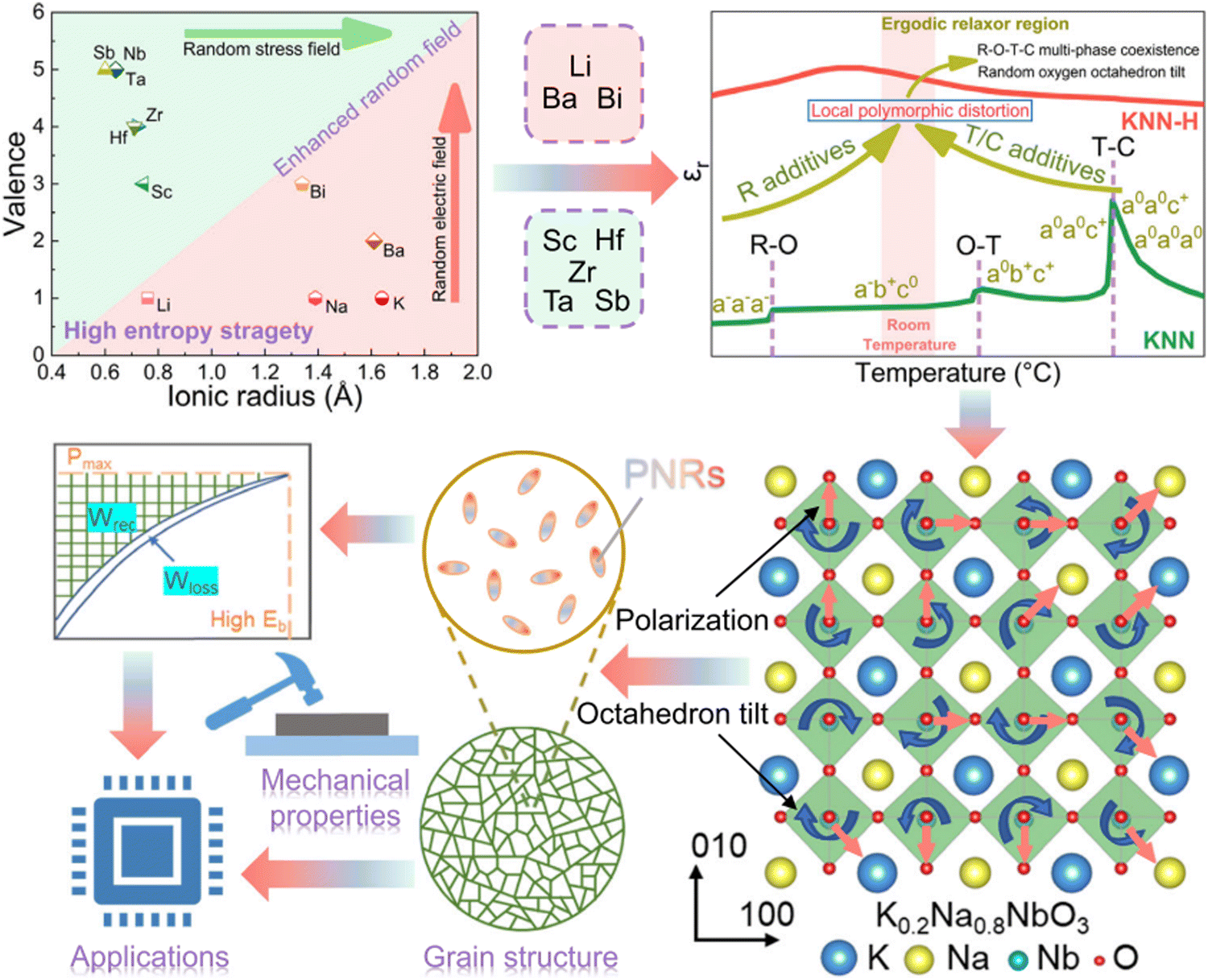 | ||
| Fig. 23 Schematic overview of high-entropy design approach for KNN-based ceramics.240 Reprinted (adapted) with permission from ref. 240 under the terms of the Creative Commons CC BY license, Springer Nature. | ||
High entropy compositions have multiple components occupying the A or B-site which is the same effective approach used in the formation of many relaxors. The characteristics of multiple polar clusters at the local scale reported in ‘high-entropy’ bulk ceramics, MLCCs and ceramic thin film are comparable to PNRs in relaxor which can be induced through multiple occupancy of A and B- sites of the perovskite structure. Therefore, the comprehensive implementation of the high-entropy strategy across different material systems does require further clarification and investigation. Although it has been claimed to be an optimisation strategy for energy density performance, it appears to be qualitatively similar to approaches in the literature reported over the last decade which are often described as pseudo-ternary, quaternary and quinary (or more) perovskite solid solutions,241–244 rather than as a single formula unit.
4.4. Processing innovation
High electro-strain in AFEs and REFs is considered a potential threat for practical applications for high field/energy density capacitors during AC/DC cycling and may cause mechanical failure along the interface between internal electrodes and ceramic layers, leading to poor MLCC reliability and early breakdown. Li and co-authors205 fabricated grain-orientated NBT-SBT MLCCs using an ST template, Fig. 24(a and b). The textured MLCCs exhibited reduced electro strain (<0.2%) in comparison to >0.5% in untextured samples, Fig. 24(c and d), realising enhanced Wrec ∼21.5 J cm−3 at Emax ∼1030 kV cm−1.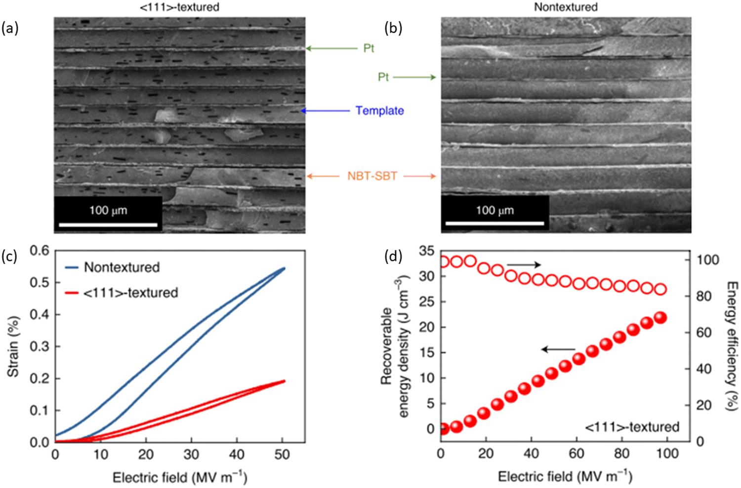 | ||
| Fig. 24 SEM cross-section of (a) textured and (b) untextured NBT-SBT MLCCs. (c) S–E Loops of textured and nontextured MLCCs. (d) The energy storage performance of textured NBT-SBT MLCCs.205 Reproduced from ref. 205 with permission from Springer Nature. | ||
Low η not only leads to a high Wloss but may also generate self-heating during charge–discharge, leading to electrical breakdown.245 A ‘sandwich’ MLCC structure, designed to optimise η composed of mixed layers of 0.35BF–0.65 ST and BNST has been reported by Yan and co-authors,246 realising improved Wrec ∼9.05 J cm−3 with high η = 97% at 710 kV cm−1, Fig. 25.
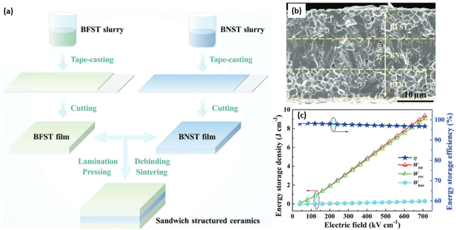 | ||
| Fig. 25 (a) Schematic illustration for preparing the sandwich BFST/BNST/BFST ceramics by tape-casting method; (b) SEM cross-section image of sandwiched structured ceramics; (c) energy storage performance of sandwiched structured ceramics.246 Reproduced from ref. 246 with permission from the John Wiley and Sons. | ||
5. Current challenges and future perspectives
5.1. Materials challenge for temperature stability
The thermal stability of dielectric materials exhibiting high energy/power density is a crucial factor for practical applications in portable electronics, electric vehicles, and pulsed power systems. Polymer-based dielectric materials offer high power/energy density at ambient temperatures, but above 100 °C, they become unreliable and susceptible to dielectric breakdown. Consequently, ceramic-based dielectric materials are prioritised and receiving increased attention due to their high polarisation, rapid charge–discharge speed (<ns), and superior thermal stability.The temperature stability of high energy density ceramics is often evaluated by performing temperature-dependent P–E measurements, simulating the environmental conditions in high-voltage capacitors. The applied electric field during temperature studies is approximately 1/4 to 1/2 of the maximum field (Emax), and the stability benchmark refers to a variation in Wrec of less than 15%. Temperature stability performance for bulk ceramics has been summarised and plotted in Fig. 26. Currently, the maximum operating temperature is 200 °C in a few NN and NBT-based bulk ceramics which offer the best average temperature stability of 160 ± 40 °C, compared to ∼110 ± 30 °C found in BF and AN-based ceramics. Recently, broad temperature stability (<10%) has also been reported in a NN based MLCCs, 0.88Na(Nb0.90Ta0.10)O3–0.1ST–0.02La(Mg,Ti)O3, up to 200 °C with Wrec ∼15 J cm−3.18
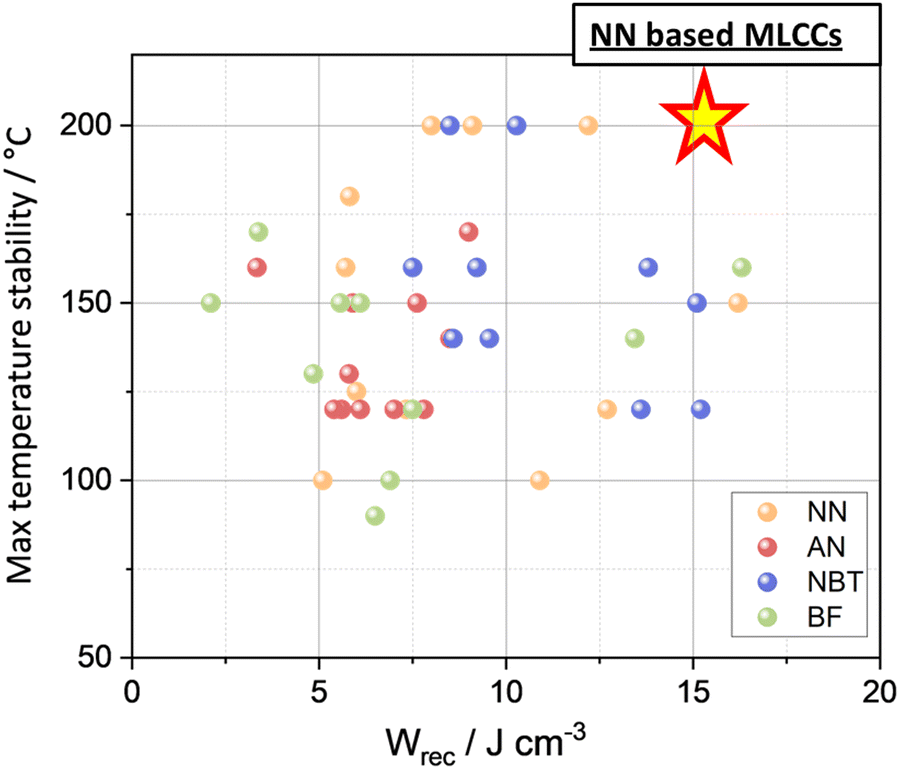 | ||
| Fig. 26 Correlation between max temperature stability and Wrec among four lead-free dielectric candidates. | ||
Two significant challenges have been identified for high-temperature operation: (i) premature mechanical/dielectric breakdown and (ii) low charge–discharge energy efficiency (η < 60%). Wrec often decreases at elevated temperatures, as evidenced by the opening of the P–E loops (reduced η) or electrical breakdown (reduced Emax). Premature dielectric/mechanical breakdown can be attributed to the electric field-induced phase switching between AFE/RFE to FE phases. Substantial electrostrain is often developed during domain reorientation and/or structural transformation from PNRs to long-range orders during high field/voltage charge–discharge electrical cycling, leading to microcrack formation along the interface between electrodes and ceramics. The decrease in η may be associated with changes in the correlation length (e.g. from short-range to meso-range) or to the motion of oxygen vacancies Vo (Under combined high voltage and temperature conditions, both electrical and thermal breakdown mechanisms may occur simultaneously when dielectric ceramics can no longer maintain electrical insulation. However, there is a lack of in-depth studies, such as in situ poling diffraction/scattering with pair distribution function (PDF) analysis and high-resolution scanning transmission electron microscopy (STEM), to reveal such features under combined thermal (up to 200 °C) and electrical loading at high electric field levels (up to 400 kV cm−1).
5.2. Process challenge on the co-fire compatibilities between dielectric ceramics with cost-effective inner electrodes
Precious metal electrodes (PMEs) like Pt or Ag/Pd (high level of Pd) are currently used as internal electrodes in most of the MLCCs reported in the literature (Table 5 above) whereas, base metal electrodes (BMEs) such as Ni or Cu, are employed in 99% of Class II high-permittivity commercial capacitors. An issue of incompatibility of BMEs with all current high energy density/voltage capacitors poses a serious challenge to achieving scalable manufacturing and system integration. Although PMEs offer robustness and long-term reliability, BMEs present a cost-effective solution for mass production.Most lead-free dielectric ceramics can be sintered with a selection of PMEs in the air without any reaction. However, Pt is too expensive for industrial manufacturing and the recent spike in Pd price, from approximately $14.3 per gram in 2012 to $30.7 per gram in 2024,245 also brings significant cost concerns for MLCC manufacturing. In contrast, the overall price trend for BMEs (Ni) between 2012 and 2021 has remained stable, approximately $0.02 per gram,247 making them a more sensible option for MLCC mass production. The high melting point of Ni (∼1455 °C) allows co-firing capability with dielectric ceramics requiring high sintering temperatures (i.e. >1200 °C for BT).248 To date, none of the reported high-energy density MLCCs have used Ni as internal electrodes. The reaction between the Ni electrode and Bi-contained dielectric materials, e.g., BF and NBT, at high temperatures results in the formation of low-resistivity and high-loss impurities. Although controlling both temperature and atmosphere (pO2) is highly complicated and dependent on the specific dielectric ceramic material, exploring co-fire compatibilities with BMEs is still the prioritised research focus to overcome this challenge, particularly for those Bi-free MLCCs cases (NN/AN-based). Co-firing of KNN-based piezoelectric multilayers with Cu internal electrodes has however been reported by Randall and co-authors.249
In addition to exploring the processing conditions with BMEs, a secondary research focus is to reduce the sintering temperature to <950 °C, allowing co-firing with Ag/10%Pd internal electrodes. Incorporating sintering aids such as glass, dopants, and/or alloying with other members encourages ceramic densification at lower temperatures by forming liquid phases.250 For example, adding a third component of Bi(Li0.5Nb0.5)O3 into BF–BT effectively reduces the sintering temperature to 890 °C, allowing the possibility to co-fire with Ag or Ag/10%Pd. CuO was also reported to lower the sintering temperature of KNN-based piezoelectric ceramics to approximately 940 °C.251
6. Summary and perspectives
6.1. Emax and equivalent voltage
Emax has been frequently reported for various dielectric ceramics, including bulk, MLCCs and thin films while an assessment of the equivalent voltage has not received adequate attention. Bulk ceramics offer the highest voltage range for capacitors, averaging between 3 to 5 kV, followed by MLCCs (1.0 to 1.6 kV). Ceramic thin films, on the other hand, provide the lowest voltage range (0.05 to 0.20 V) due to their reduced thickness. Presently, commercial high-voltage capacitors offer a range of 400 to 800 V. State-of-the-art MLCCs now meet future voltage requirements for many high voltage/energy density applications but are limited by either the use of PME internal electrodes or their temperature stability is insufficient. In contrast, the PVD routes required to fabricate ceramic thin films are expensive and may only experience exploitation when directly integrated into Si technology.6.2. Temperature stability
NN and NBT-based bulk ceramics currently offer the best average temperature stabilities of 160 ± 40 °C, while AN and BF-based bulk ceramics experience >15% drops in Wrec at temperatures above 150 °C. The electric field applied in almost every temperature study reaches only 1/4 to 1/2 of the Emax, equivalent to 1–2 kV for bulk ceramics and 0.4–0.8 kV in MLCCs, which is too low for practical applications. To enhance temperature stability, further research is required to understand field-induced AFE/FE and short- to long-range phase transitions. Most importantly, the defect chemistry which controls the conductivity at higher fields and temperatures requires further investigation.Currently, there is a lack of in situ structural and electrical microstructural analysis under high field and temperature which modifies the operating conditions of a capacitor. More advanced structural analysis techniques, e.g., synchrotron X-ray/neutron scattering, high-resolution STEM, in situ Raman spectroscopy, and local probe atomic force microscopy, as well as advanced electrical microstructural analysis techniques e.g., local probe impedance, are desirable for further understanding temperature instabilities and dielectric/mechanical breakdown mechanism(s) under high fields and high temperatures. Additionally, there is a critical need to investigate the intrinsic polarisation mechanisms in lead-free dielectric/ferroelectric ceramics to better understand the origins of ultrahigh polarisation values reported in some materials.
6.3. Charge–discharge efficiency (η)
Low η implies high energy consumption during electrical charging and discharging, which is not ideal for AC/DC cycles. NBT currently offers the highest η of ∼89%, followed by NN (∼84%), BF (∼75%), and AN (∼71%). Recent studies have focused more on RFE-type dielectrics, e.g., NBT, realising high η over AFE-type dielectrics (e.g., AN and NN). To understand the origin of low η at room or elevated temperatures, the local structural analysis and electrical microstructure of dielectric ceramics must be closely examined. Possible reasons include electric field-induced phase transition(s), motion of oxygen vacancies, changes in resistivity, capacitance, activated energy and electrical homogeneity.6.4. MLCC development
The chemical reaction between Bi-based dielectrics and low-cost internal electrodes, such as Ag and Ni (under a controlled atmosphere), significantly restricts their potential for large-scale manufacture. AN and NN-based dielectrics offer the possibility of co-firing with cost-effective (BME) electrodes, although Ag/30Pd and Pt were still used in the literature. For AN and NN-based ceramics, glass additions could be used to reduce the sintering temperature, increasing compatibility with cost-effective electrodes. This would also decrease resistivity in grain boundaries, increase density and create a more uniform microstructure, all of which enhance the breakdown strength of the ceramic layers.249 Similar strategies have been successfully employed in BT MLCCs. Recent developments in academia and industry have focused on improving the volumetric efficiency and reliability of MLCCs, driven by the demand for advanced electronics and electric vehicles. Notable companies leading these advancements include Murata Manufacturing, TDK Corporation, and Samsung Electro-Mechanics.Data availability
No primary research results, software or code have been included and no new data were generated or analysed as part of this review.Conflicts of interest
There is no conflict of interest related to this publicationAcknowledgements
The authors gratefully acknowledge the support of the Dame Kathleen Ollerenshaw Fellowship and Dean's PhD Scholarship provided by The University of Manchester, and the Royal Society of Chemistry Research Fund Grant R23-0577995877 and R23-5982928392.References
- Electricity 2024 – Analysis - IEA, https://www.iea.org/reports/electricity-2024, (accessed 19 February 2024).
- X. Luo, J. Wang, M. Dooner and J. Clarke, Appl. Energy, 2015, 137, 511–536 CrossRef.
- L. Pardo, F. Carmona, C. Alemany and B. Jimenez, Ferroelectrics, 1992, 134, 77–82 CrossRef.
- A. Stebnberg, Ferroelectrics, 1992, 134, 29–34 CrossRef.
- D. K. Das-gupta and Z. Shuren, Ferroelectrics, 1992, 134, 71–76 CrossRef.
- S. A. Sherrill, P. Banerjee, G. W. Rubloff and S. B. Lee, Phys. Chem. Chem. Phys., 2011, 13, 20714–20723 RSC.
- Capacitor Bank Market Size, https://www.gminsights.com/industry-analysis/capacitor-bank-market/market-size, (accessed 20 March 2024).
- D. V. Ragone, SAE Technical Papers DOI:10.4271/680453.
- SLC or MLCC Ceramic Capacitor: When it Fits Better?, https://passive-components.eu/slc-or-mlcc-ceramic-capacitor-when-it-fits-better/, (accessed 29 February 2024).
- G. Liu, Y. Li, B. Guo, M. Tang, Q. Li, J. Dong, L. Yu, K. Yu, Y. Yan, D. Wang, L. Zhang, H. Zhang, Z. He and L. Jin, Chem. Eng. J., 2021, 419, 129673 CrossRef.
- Lead Zirconate Titanate Market Size Report, 2021-2026, https://www.industryarc.com/Report/16050/lead-zirconate-titanate-market.html, (accessed 18 March 2024).
- Y. Chen, D. Zhang, Z. Peng, M. Yuan and X. Ji, Front. Mater., 2021, 8, 679167 CrossRef.
- Knowles Precision Devices Capacitors For Electric Vehicles, https://info.knowlescapacitors.com/knowles-precision-devices-capacitors-for-electric-vehicles, (accessed 29 February 2024).
- Multi-layer Ceramic Capacitor (MLCC) Market to Reach $16.77 Billion by 2030 - Y5V Segment Anticipated to Register Noteworthy Growth, Marking It as an Area Ripe for Opportunities, https://shorturl.at/7NaAl (accessed 29 February 2024).
- J. W. Park, J. H. Chae, I. H. Park, H. J. Youn and Y. H. Moon, J. Am. Ceram. Soc., 2007, 90, 2151–2158 CrossRef.
- S. C. Das, A. Majumdar, A. Shahee, N. P. Lalla, T. Shripathi and R. Hippler, Ferroelectr. Lett.Sect., 2011, 38, 78–85 CrossRef.
- X. Hao, J. Adv. Dielectr., 2013, 3(01), 1330001 CrossRef.
- S. C. Abrahams, S. K. Kurtz and P. B. Jamieson, Phys. Rev., 1968, 172(2), 551 CrossRef.
- Y. Shimakawa, Y. Kubo, Y. Nakagawa, S. Goto, T. Kamiyama and H. Asano, Phys. Rev. B: Condens. Matter Mater. Phys., 2000, 61, 6559 CrossRef.
- H. Zhang, M. Krynski, A. D. Fortes, T. G. Saunders, M. Palma, Y. Hao, F. Krok, H. Yan and I. Abrahams, J. Am. Chem. Soc., 2024, 146, 5569–5579 CrossRef PubMed.
- X. Tang, Z. Hu, V. Koval, B. Yang, G. Smith and H. Yan, Chem. Eng. J., 2023, 473, 145363 CrossRef.
- Z. Chen, S. Mao, L. Ma, G. Luo, Q. Feng, Z. Cen, F. Toyohisa, X. Peng, L. Liu, H. Zhou, C. Hu and N. Luo, J. Materiomics, 2022, 8, 753–762 CrossRef.
- Z. Pan, L. Yao, G. Ge, B. Shen and J. Zhai, J. Mater. Chem. A, 2018, 6, 14614–14622 RSC.
- H. D. Megaw, Ferroelectrics, 1974, 7, 87–89 CrossRef.
- X. Tan, C. Ma, J. Frederick, S. Beckman and K. G. Webber, J. Am. Ceram. Soc., 2011, 94, 4091–4107 CrossRef.
- M. Ahtee, A. M. Glazer and H. D. Megaw, Philos. Mag., 1972, 26, 995–1014 CrossRef.
- L. Eric Cross, Ferroelectrics, 1987, 76, 241–267 CrossRef.
- J. Ma, Y. Lin, H. Yang and J. Tian, J. Alloys Compd., 2021, 868, 159206 CrossRef.
- G. Wang, Z. Lu, Y. Li, L. Li, H. Ji, A. Feteira, D. Zhou, D. Wang, S. Zhang and I. M. Reaney, Chem. Rev., 2021, 121, 6124–6172 CrossRef.
- H. Qi, A. Xie, A. Tian and R. Zuo, Adv. Energy Mater., 2020, 10(6), 1903338 CrossRef.
- P. Nong, Y. Pan, Q. Dong, D. Zeng, M. Xu, X. Wang, J. Wang, L. Deng, X. Chen and H. Zhou, Electron. Mater. Lett., 2023, 1, 1–13 Search PubMed.
- X. Wang, H. Chen, Y. Pan, Q. Dong, J. Wang, X. Chen and H. Zhou, J. Power Sources, 2023, 566, 232934 CrossRef.
- L. Ma, Z. Chen, G. Luo, Z. Che, C. Xu, D. Shan, Z. Cen, Q. Feng, X. Chen, T. Fujita, Y. Zhu, Y. Liu, J.-F. Li, S. Zhang and N. Luo, J. Materiomics, 2024, 10(5), 1026–1035 CrossRef.
- Y. Fan, Z. Zhou, R. Liang, M. Zhou and X. Dong, J. Eur. Ceram. Soc., 2019, 39, 4712–4718 CrossRef.
- A. Yadav, I. P. Raevski and P. M. Sarun, Mater. Today Commun., 2022, 33, 104712 CrossRef.
- F. Ye, X. Jiang, X. Huang, R. Zeng, C. Chen, X. Nie and H. Cheng, J. Mater. Sci.: Mater. Electron., 2022, 33, 4497–4509 CrossRef.
- A. Yadav, S. Sahoo, S. Singh, I. P. Raevski and P. M. Sarun, Mater. Sci. Eng., B, 2023, 297, 116796 CrossRef.
- W. Yang, H. Zeng, F. Yan, J. Lin, G. Ge, Y. Cao, W. Du, K. Zhao, G. Li, H. Xie and J. Zhai, J. Mater. Chem. A, 2022, 10, 11613–11624 RSC.
- J. Ye, G. Wang, M. Zhou, N. Liu, X. Chen, S. Li, F. Cao and X. Dong, J. Mater. Chem C, 2019, 7(19), 5639–5645 RSC.
- C. S. Htet, A. M. Manjón-Sanz, J. Liu, C. Babori, M. Barati, F. P. Marlton, L. Daniel, M. R. V. Jørgensen and A. Pramanick, J. Eur. Ceram. Soc., 2024, 44, 1597–1609 CrossRef.
- X. Dong, X. Li, X. Chen, H. Chen, C. Sun, J. Shi, F. Pang and H. Zhou, Ceram. Int., 2021, 47, 3079–3088 CrossRef.
- A. Xie, J. Fu, R. Zuo, C. Zhou, Z. Qiao, T. Li and S. Zhang, Chem. Eng. J., 2022, 429, 132534 CrossRef.
- W. Xiao, Z. Liu, C. Zhang, Z. Dou, B. Fan, M. Shen, Y. Yang, W. Luo, K. Li, Q. Fu, S. Jiang, Y. Wang and G. Zhang, Chem. Eng. J., 2023, 461, 142070 CrossRef.
- D. Yang, Y. Wang, X. Wang, C. Chen, L. Li, M. Yao, L. Miao, R. Ma, H. Cheng and D. Hu, Ceram. Int., 2023, 49, 7814–7822 CrossRef.
- R. Muhammad, A. Ali, J. Camargo, M. S. Castro, W. Lei, K. Song and D. Wang, Crystals, 2022, 12, 141 CrossRef.
- J. Fu, H. Qi, A. Xie, A. Tian and R. Zuo, Acta Mater., 2021, 215, 117100 CrossRef CAS.
- L. Wang, S. Sun, H. Luo, Y. Ren, H. Liu, X. Xing and J. Chen, J. Mater. Chem. A, 2021, 9, 2367–2374 RSC.
- G. Liu, L. Chen and H. Qi, Microstructures, 2023, 3 Search PubMed; G. Liu, L. Chen and H. Qi, Chem. Eng. J., 2019, 3, 2023009 Search PubMed.
- M. H. Zhang, H. Ding, S. Egert, C. Zhao, L. Villa, L. Fulanović, P. B. Groszewicz, G. Buntkowsky, H. J. Kleebe, K. Albe, A. Klein and J. Koruza, Nat. Commun., 2023, 14, 1–11 Search PubMed.
- S. Zhang, W. Li, Y. Zhang, X. Tang, Y. Jiang and X. Guo, Mater. Sci. Eng., B, 2024, 299, 117025 CrossRef CAS.
- P. Nong, D. Zeng, Y. Pan, Q. Dong, M. Xu, X. Wang, J. Wang, H. Zhou, X. Li and X. Chen, J. Materiomics, 2019, 10(3), 670–681 CrossRef.
- M. H. Zhang, L. Fulanović, C. Zhao and J. Koruza, J. Materiomics, 2023, 9, 1–18 CrossRef.
- J. Joseph, Z. Cheng and S. Zhang, J. Materiomics, 2022, 8, 731–738 CrossRef.
- Z. Wang, J. Zhao, G. Niu, N. Zhang, K. Zheng, Y. Quan, L. Wang, J. Zhuang, G. Wang, X. Li, H. Cai, M. Liu, Z. Jiang, Y. Zhao and W. Ren, J. Eur. Ceram. Soc., 2023, 43, 5511–5520 CrossRef CAS.
- J. Ma, J. Zhang, J. Guo, X. Li, S. Guo, Y. Huan, J. Wang, S. T. Zhang and Y. Wang, Chem. Mater., 2022, 34, 7313–7322 CrossRef CAS.
- V. M. Goldschmidt, Naturwissenschaften, 1926, 14, 477–485 CrossRef CAS.
- H. Shimizu, H. Guo, S. E. Reyes-Lillo, Y. Mizuno, K. M. Rabe and C. A. Randall, Dalton Trans., 2015, 44, 10763–10772 RSC.
- C. Liang, C. Wang, W. Cao, H. Zhao, F. Li and C. Wang, J. Adv. Dielectr., 2023, 13, 2242004 CrossRef CAS.
- M. Xu, X. Wang, P. Nong, D. Zeng, Q. Dong, Y. Pan, J. Wang, H. Zhou and X. Chen, ACS Appl. Energy Mater., 2023, 6, 1630–1638 CrossRef CAS.
- R. Kang, Z. Wang, W. Yang, X. Zhu, P. Shi, Y. Gao, P. Mao, J. Zhao, L. Zhang and X. Lou, J. Mater. Chem. A, 2021, 9, 24387–24396 RSC.
- H. Chen, J. Shi, X. Chen, C. Sun, F. Pang, X. Dong, H. Zhang and H. Zhou, J. Mater. Chem. A, 2021, 9, 4789–4799 RSC.
- H. Li, Z. Pan, X. Chen, J. Zhao, L. Tang, J. Liu, P. Li and J. Zhai, Mater. Today Phys., 2023, 38, 101208 CrossRef CAS.
- J. Jiang, X. Meng, L. Li, J. Zhang, S. Guo, J. Wang, X. Hao, H. Zhu and S. T. Zhang, Chem. Eng. J., 2021, 422, 130130 CrossRef CAS.
- H. Qi, R. Zuo, A. Xie, A. Tian, J. Fu, Y. Zhang, S. Zhang, H. Qi, R. Z. Zuo, A. W. Xie, A. Tian, J. Fu, Y. Zhang and S. J. Zhang, Adv. Funct. Mater., 2019, 29, 1903877 CrossRef.
- J. Ma, D. Zhang, F. Ying, X. Li, L. Li, S. Guo, Y. Huan, J. Zhang, J. Wang and S. T. Zhang, ACS Appl. Mater. Interfaces, 2022, 14, 19704–19713 CrossRef CAS PubMed.
- T. Pan, J. Zhang, Z. N. Guan, Y. Yan, J. Ma, X. Li, S. Guo, J. Wang and Y. Wang, Adv. Electron. Mater., 2022, 8, 2200793 CrossRef CAS.
- D. Fu, M. Endo, H. Taniguchi, T. Taniyama and M. Ltoh, Appl. Phys. Lett., 2007, 90, 252907 CrossRef.
- L. Zhao, Q. Liu, S. Zhang and J. F. Li, J. Mater. Chem. C, 2016, 4, 8380–8384 RSC.
- Z. Zheng, Y. Yang, L. Zhao, K. Zhu, H. Yang and J. Wang, Ceram. Int., 2024, 50, 3902–3911 CrossRef CAS.
- H. Yuan, X. Fan, Z. Zheng, M. Zhao, L. Zhao, K. Zhu and J. Wang, Chem. Eng. J., 2023, 456, 141023 CrossRef CAS.
- L. F. Zhu, S. Deng, L. Zhao, G. Li, Q. Wang, L. Li, Y. Yan, H. Qi, B. P. Zhang, J. Chen and J. F. Li, Nat. Commun., 2023, 14(1), 1166 CrossRef CAS PubMed.
- M. Zhao, J. Wang, J. Zhang, L. F. Zhu and L. Zhao, J. Adv. Ceram., 2023, 12, 1166–1177 CrossRef CAS.
- M. Zhao, J. Wang, H. Yuan, Z. Zheng and L. Zhao, J. Materiomics, 2023, 9, 19–26 CrossRef.
- L. Wang, Z. Zheng, H. Yuan, Y. Yang, J. Zhang, K. Zhu, X. Hu and J. Wang, J. Eur. Ceram. Soc., 2024, 44, 2934–2943 CrossRef CAS.
- Z. Lu, W. Bao, G. Wang, S. K. Sun, L. Li, J. Li, H. Yang, H. Ji, A. Feteira, D. Li, F. Xu, A. K. Kleppe, D. Wang, S. Y. Liu and I. M. Reaney, Nano Energy, 2021, 79, 105423 CrossRef CAS.
- Y. Tian, J. Li, Q. Hu, K. Yu, Y. Zhuang, G. Viola, I. Abrahams, Z. Xu, X. Wei, H. Yan, C. Y. Tian, L. Jin, Q. Hu, K. Yu, Y. Zhuang, G. Viola, I. Abrahams, Z. Xu, X. Wei and H. Yan, J. Mater. Chem. A, 2019, 7(2), 834–842 RSC.
- J. Wang, X. Fan, Z. Liu, K. Zhu, H. Yuan, Z. Zheng, L. Zhao, J. Zhang, Q. Yuan and J. F. Li, J. Mater. Chem. A, 2023, 11, 22512–22521 RSC.
- S. Li, T. Hu, H. Nie, Z. Fu, C. Xu, F. Xu, G. Wang and X. Dong, Energy Storage Mater., 2021, 34, 417–426 CrossRef.
- Y. Xu, Z. Yang, K. Xu, J. Tian, D. Zhang, M. Zhan, H. Tian, X. Cai, B. Zhang, Y. Yan, L. Guo, G. Wang, L. Lin, J. Fan, T. Wang and Y. Tian, J. Alloys Compd., 2022, 913, 165313 CrossRef CAS.
- Y. Xu, Z. Yang, K. Xu, Y. Cao, Y. Tian, L. Guo, J. Tian, H. Tian, X. Liu, L. Lin and G. Wang, Chem. Eng. J., 2021, 426, 131047 CrossRef CAS.
- Z. Lu, D. Sun, G. Wang, J. Zhao, B. Zhang, D. Wang and I. Shyha, J. Adv. Dielectr., 2023, 13, 2242006 CrossRef CAS.
- J. Zhou, J. Du, L. Chen, Y. Li, L. Xu, Q. Zhao, H. Yang, J. Ding, Z. Sun, X. Hao and X. Wang, J. Eur. Ceram. Soc., 2023, 43, 6059–6068 CrossRef CAS.
- X. Fan, J. Wang, H. Yuan, L. Chen, L. Zhao and K. Zhu, ACS Appl. Mater. Interfaces, 2022, 14, 7052–7062 CrossRef CAS PubMed.
- B. Li, Z. Yan, X. Zhou, H. Qi, V. Koval, X. Luo, H. Luo, H. Yan and D. Zhang, ACS Appl. Mater. Interfaces, 2023, 15, 4246–4256 CrossRef CAS PubMed.
- S. Gao, Y. Huang, Y. Jiang, M. Shen, H. Huang, S. Jiang, Y. He and Q. Zhang, Acta Mater., 2023, 246, 118730 CrossRef CAS.
- G. Wang, Z. Lu, Z. Zhang, A. Feteria, C. Tang and D. A. Halls, J. Am. Ceram. Soc., 2019, 102(12), 7746–7754, DOI:10.1111/jace.16676.
- F. Yang, P. Wu and D. C. Sinclair, Solid State Ionics, 2017, 299, 38–45 CrossRef CAS.
- Z. Pan, D. Hu, Y. Zhang, J. Liu, B. Shen and J. Zhai, J. Mater. Chem. C, 2019, 7, 4072–4078 RSC.
- H. Ji, D. Wang, W. Bao, Z. Lu, G. Wang, H. Yang, A. Mostaed, L. Li, A. Feteira, S. Sun, F. Xu, D. Li, C. J. Ma, S. Y. Liu and I. M. Reaney, Energy Storage Mater., 2021, 38, 113–120 CrossRef.
- A. Khan, N. S. Gul, M. Luo, J. Wu, S. Z. Khan, A. Manan, X. J. Wang and T. M. Khan, Front. Chem., 2022, 10, 1025030 CrossRef CAS PubMed.
- B. J. Chu, D. R. Chen, G. R. Li and Q. R. Yin, J. Eur. Ceram. Soc., 2002, 22, 2115 CrossRef CAS.
- K. Liu, Y. Zhang, M. A. Marwat, G. Wang, D. Wang, W. Ma, T. Wei, M. li, J. Xu, H. Yang, S. Kongparakul, C. Samart, J. Zang, P. Fan and H. Zhang, J. Am. Ceram. Soc., 2020, 103, 3739–3747 CrossRef CAS.
- E. Aksel, J. S. Forrester, J. L. Jones, P. A. Thomas, K. Page and M. R. Suchomel, Appl. Phys. Lett., 2011, 15, 98 Search PubMed.
- K. Datta, P. Thomas and K. Roleder, Phys. Rev. B: Condens. Matter Mater. Phys., 2010, 82(22), 224105 CrossRef.
- M. Li, M. J. Pietrowski, R. A. De Souza, H. Zhang, I. M. Reaney, S. N. Cook, J. A. Kilner and D. C. Sinclair, Nat. Mater., 2014, 13, 31–36 CrossRef CAS PubMed.
- A. P. Hoang, S. Steiner, F. Yang, L. Li, D. C. Sinclair and T. Fromling, J. Am. Ceram. Soc., 2021, 14(4), 2587–2595 Search PubMed.
- R. Sahu, R. R. Negi, B. Samanta, D. Nanda and P. Kumar, J. Mater. Sci.: Mater. Electron., 2021, 32, 17524–17533 CrossRef CAS.
- J. S. Kim, B. C. Choi, J. H. Jeong, K. S. Lee and S. B. Cho, Ferroelectrics, 2009, 384, 120–125 CrossRef CAS.
- G. Liu, L. Hu, Y. Wang, Z. Wang, L. Yu, J. Lv, J. Dong, Y. Wang, M. Tang, B. Guo, K. Yu and Y. Yan, Ceram. Int., 2020, 46, 19375–19384 CrossRef CAS.
- S. Lenka, T. Badapanda, S. P. Ghosh, T. Richhariya, S. Sarangi and S. N. Tripathy, Mater. Today Commun., 2023, 36, 106738 CrossRef CAS.
- X. Qiao, F. Zhang, D. Wu, B. Chen, X. Zhao, Z. Peng, X. Ren, P. Liang, X. Chao and Z. Yang, Chem. Eng. J., 2020, 388, 124158 CrossRef CAS.
- W. Q. Luo, Z. Y. Shen, Y. Y. Yu, F. S. Song, Z. M. Wang and Y. M. Li DOI:10.1142/S2010135X18200047.
- H. Borkar, V. N. Singh, B. P. Singh, M. Tomar, V. Gupta and A. Kumar, RSC Adv., 2014, 4, 22840–22847 RSC.
- J. Wu, A. Mahajan, L. Riekehr, H. Zhang, B. Yang, N. Meng, Z. Zhang and H. Yan, Nano Energy, 2018, 50, 723–732 CrossRef CAS.
- L. Zhang, Y. Pu, M. Chen, T. Wei and X. Peng, Chem. Eng. J., 2020, 383, 123154 CrossRef CAS.
- Z. Liu, A. Zhang, S. Xu, J. Lu, B. Xie, K. Guo and Y. Mao, J. Alloys Compd., 2020, 823, 153772 CrossRef CAS.
- W. Cao, W. Li, T. Zhang, J. Sheng, Y. Hou, Y. Feng, Y. Yu and W. Fei, Energy Technol., 2015, 3, 1198–1204 CrossRef CAS.
- D. Hu, Z. Pan, X. Zhang, H. Ye, Z. He, M. Wang, S. Xing, J. Zhai, Q. Fu and J. Liu, J. Mater. Chem. C, 2020, 8, 591–601 RSC.
- K. R. Kandula, K. Banerjee, S. S. K. Raavi and S. Asthana, Phys. Status Solidi A, 2004, 16(26), 5610–5615 Search PubMed.
- A. Kumar, R. Kumar, K. Singh and S. Singh, Phys. Status Solidi A, 2021, 1–79 Search PubMed.
- P. Chen, L. Zhang, J. Cai, Z. Wang, W. Shi, J. Jing, F. Wei, G. Liu, Y. Yan, H. Liu and L. Jin, J. Mater. Sci.: Mater. Electron., 2019, 30, 13556–13566 CrossRef CAS.
- C. Cui, Y. Pu and R. Shi, J. Alloys Compd., 2018, 740, 1180–1187 CrossRef CAS.
- C. Wang, F. Yan, H. Yang, Y. Lin and T. Wang, J. Alloys Compd., 2018, 749, 605–611 CrossRef CAS.
- J. Li, F. Li, Z. Xu and S. Zhang, Adv. Mater., 2021, 90, 106528 Search PubMed.
- F. Yang, M. Li, L. Li, P. Wu, E. Pradal-Velázquez and D. C. Sinclair, J. Mater. Chem. A, 2018, 6, 5243–5254 RSC.
- D. P. C. Shih, A. Aguadero and S. J. Skinner, J. Am. Ceram. Soc., 2023, 106, 100–108 CrossRef CAS.
- J. Suchanicz, M. Wąs, M. Nowakowska-Malczyk, D. Sitko, K. Kluczewska-Chmielarz, K. Konieczny, G. Jagło, P. Czaja, B. Handke, Z. Kucia, P. Zając and K. Łyszczarz, Materials, 2022, 15(18), 6204 CrossRef CAS PubMed.
- W.-Q. Luo, Z.-Y. Shen, Y.-Y. Yu, F.-S. Song, Z.-M. Wang and Y.-M. Li DOI:10.1142/S2010135X18200047.
- I. Tae DOI:10.1111/jace.16401.
- W. P. Cao, J. Sheng, Z. Liu, C. Gao, Z. H. Wang, J. Wang, J. Chang, Z. Wang and W. L. Li, Mod. Phys. Lett. B, 2020, 34(11), 2050100 CrossRef CAS.
- S. T. Zhang, F. Yan, B. Yang and W. Cao, Appl. Phys. Lett., 2010, 97(12), 1 Search PubMed.
- M. A. Rahman, J. Asian Ceram. Soc., 2023, 11, 215–224 CrossRef.
- Y. S. Zhang, W. H. Li, X. G. Tang, K. Meng, S. Y. Zhang, X. Z. Xiao, X. Bin Guo, Y. P. Jiang and Z. Tang, J. Alloys Compd., 2022, 911, 165074 CrossRef CAS.
- L. Yang, X. Kong, Z. Cheng and S. Zhang, J. Mater. Chem. A, 2019, 7, 8573–8580 RSC.
- L. Zhang, Y. Pu and M. Chen, Ceram. Int., 2020, 46, 98–105 CrossRef.
- Q. Xu, H. Liu, L. Zhang, J. Xie, H. Hao, M. Cao, Z. Yao and M. T. Lanagan, RSC Adv., 2016, 6, 59280–59291 RSC.
- Z. Yang, Y. Yuan, L. Cao, E. Li and S. Zhang, Ceram. Int., 2020, 46, 11282–11289 CrossRef CAS.
- G. Liu, J. Dong, L. Zhang, L. Yu, F. Wei, Y. Li, J. Gao, J. Hu, Y. Yan, Q. Li, K. Yu and L. Jin, Ceram. Int., 2020, 46, 11680–11688 CrossRef CAS.
- L. Zhang, Y. Pu and M. Chen, J. Alloys Compd., 2019, 775, 342–347 CrossRef CAS.
- P. Chen and B. Chu, J. Eur. Ceram. Soc., 2016, 36, 81–88 CrossRef CAS.
- P. Butnoi, S. Manotham, P. Jaita, C. Randorn and G. Rujijanagul, J. Eur. Ceram. Soc., 2018, 38, 3822–3832 CrossRef CAS.
- J. Sui, H. Fan, B. Hu and L. Ning, Ceram. Int., 2018, 44, 18054–18059 CrossRef CAS.
- L. Zhang, Y. Pu, M. Chen, T. Wei, W. Keipper, R. Shi, X. Guo, R. Li and X. Peng, J. Eur. Ceram. Soc., 2020, 40, 71–77 CrossRef CAS.
- B. Hu, H. Fan, L. Ning, Y. Wen and C. Wang, Ceram. Int., 2018, 44, 15160–15166 CrossRef CAS.
- Y. Xu, Y. Hou, H. Zhao, M. Zheng and M. Zhu, Mater. Lett., 2019, 249, 21–24 CrossRef CAS.
- L. Zhang, Y. Pu, M. Chen, R. Li, X. Guo and Y. Cui, Ceram. Int., 2018, 44, S207–S210 CrossRef CAS.
- X. Liu, H. Yang, F. Yan, Y. Qin, Y. Lin and T. Wang, J. Alloys Compd., 2019, 778, 97–104 CrossRef CAS.
- J. Yin, X. Lv and J. Wu, Ceram. Int., 2017, 43, 13541–13546 CrossRef CAS.
- M. Yao, Y. Pu, L. Zhang and M. Chen, Mater. Lett., 2016, 174, 110–113 CrossRef CAS.
- P. Ren, Z. Liu, X. Wang, Z. Duan, Y. Wan, F. Yan and G. Zhao, J. Alloys Compd., 2018, 742, 683–689 CrossRef CAS.
- Y. Qiu, Y. Lin, X. Liu and H. Yang, J. Alloys Compd., 2019, 797, 348–355 CrossRef CAS.
- Y. Huang, F. Li, H. Hao, F. Xia, H. Liu and S. Zhang, J. Materiomics, 2019, 5, 385–393 CrossRef.
- R. Sahu, R. R. Negi, B. Samanta, D. Nanda and P. Kumar, J. Mater. Sci.: Mater. Electron., 2021, 32, 17524–17533 CrossRef CAS.
- S. Dagar, A. Hooda, S. Khasa and M. Malik, Mater. Chem. Phys., 2020, 249, 123214 CrossRef CAS.
- C. Wu, X. Qiu, C. Liu, H. Zhao, L. Chen, W. Ge and M. Yao, Phys. Status Solidi A, 2022, 219, 2100737 CrossRef CAS.
- H. Wang, Q. Li, Y. Jia, A. K. Yadav, B. Yan, Q. Shen, M. Li, Q. Quan and H. Fan, J. Mater. Sci., 2021, 56, 14672–14683 CrossRef CAS.
- Y. Qiao, W. Li, Y. Zhao, Y. Zhang, W. Cao and W. Fei, ACS Appl. Energy Mater., 2018, 1, 956–962 CrossRef CAS.
- J. A. Dawson, H. Chen and I. Tanaka, J. Mater. Chem. A, 2015, 3, 16574–16582 RSC.
- X. He and Y. Mo, Phys. Chem. Chem. Phys., 2015, 17, 18035–18044 RSC.
- C. Wu, X. Qiu, W. Ge, C. Liu, H. Zhao, L. Chen, Z. Liu, L. Li and J. G. Fisher, Ceram. Int., 2022, 48, 31931–31940 CrossRef CAS.
- X. Zhang, F. Yang, W. Miao, Z. Su, J. Zhao, L. Tang, Y. Shen, D. Hu, Y. Chen, P. Li, J. Liu and Z. Pan, J. Alloys Compd., 2021, 883, 160837 CrossRef CAS.
- Z. Jiang, Z. Yang, Y. Yuan, B. Tang and S. Zhang, J. Alloys Compd., 2021, 851, 156821 CrossRef CAS.
- A. M. Balakt, C. P. Shaw and Q. Zhang, J. Alloys Compd., 2017, 709, 82–91 CrossRef CAS.
- T. Zhao, K. Shi, C. Fei, X. Sun, Y. Quan, W. Liu, J. Zhang and X. Dai, Crystals, 2023, 13, 433 CrossRef CAS.
- X. P. Jiang, X. L. Fu, C. Chen, N. Tu, M. Z. Xu, X. H. Li, H. Shao and Y. J. Chen, J. Adv. Ceram., 2015, 4, 54–60 CrossRef CAS.
- J. Xi, J. Xing, H. Chen, F. Zhang, Q. Chen, W. Zhang and J. Zhu, J. Alloys Compd., 2021, 868, 159216 CrossRef CAS.
- H. Guo, Y. Li, Y. Zhang, H. Sun and X. Liu, J. Mater. Sci.: Mater. Electron., 2018, 29, 19063–19069 CrossRef CAS.
- W. Cao, R. Lin, X. Hou, L. Li, F. Li, D. Bo, B. Ge, D. Song, J. Zhang, Z. Cheng and C. Wang, Adv. Funct. Mater., 2023, 33, 2301027 CrossRef CAS.
- D. Li, D. Xu, W. Zhao, M. Avdeev, H. Jing, Y. Guo, T. Zhou, W. Liu, D. Wang and D. Zhou, Energy Environ. Sci., 2023, 16, 4511–4521 RSC.
- J. Yin, X. Shi, H. Tao, Z. Tan, X. Lv, X. Ding, J. Sun, Y. Zhang, X. Zhang, K. Yao, J. Zhu, H. Huang, H. Wu, S. Zhang and J. Wu, Nat. Commun., 2022, 13, 1–9 Search PubMed.
- H. Liu, Z. Sun, J. Zhang, H. Luo, Q. Zhang, Y. Yao, S. Deng, H. Qi, J. Liu, L. C. Gallington, J. C. Neuefeind and J. Chen, J. Am. Chem. Soc., 2023, 145, 11764–11772 CrossRef CAS PubMed.
- H. Liu, Z. Sun, J. Zhang, H. Luo, Y. Yao, X. Wang, H. Qi, S. Deng, J. Liu, L. C. Gallington, Y. Zhang, J. C. Neuefeind and J. Chen, J. Am. Chem. Soc., 2023, 145, 19396–19404 CrossRef CAS PubMed.
- M. Jiang, Z. Peng, Q. Zhou, D. Wu, L. Wei, P. Liang, X. Chao and Z. Yang DOI:10.1142/S2010135X23400052.
- K. Wang, W. Li, X. Tang, S. Zhang, Y. Zhang, J. Hu, Z. Shen, Y. Jiang and X. Guo, J. Adv. Dielectr., 2023, 13, 2350008 CrossRef CAS.
- D. Li, D. Zhou, D. Wang, W. Zhao, Y. Guo, Z. Shi, T. Zhou, S. K. Sun, C. Singh, S. Trukhanov and A. S. B. Sombra, Small, 2023, 19, 2206958 CrossRef CAS PubMed.
- X. Zhu, Y. Gao, P. Shi, R. Kang, F. Kang, W. Qiao, J. Zhao, Z. Wang, Y. Yuan and X. Lou, Nano Energy, 2022, 98, 107276 CrossRef CAS.
- M. Wang, Q. Feng, C. Luo, Y. Lan, C. Yuan, N. Luo, C. Zhou, T. Fujita, J. Xu, G. Chen and Y. Wei, ACS Appl. Mater. Interfaces, 2021, 13, 51218–51229 CrossRef CAS PubMed.
- W. Zhao, D. Xu, D. Li, M. Avdeev, H. Jing, M. Xu, Y. Guo, D. Shi, T. Zhou, W. Liu, D. Wang and D. Zhou, Nat. Commun., 2023, 14, 1–11 Search PubMed.
- T. Li, X. Jiang, J. Li, A. Xie, J. Fu and R. Zuo, ACS Appl. Mater. Interfaces, 2022, 14, 22263–22269 CrossRef CAS PubMed.
- H. Liu, Z. Sun, J. Zhang, H. Luo, Q. Zhang, Y. Yao, S. Deng, H. Qi, J. Liu, L. C. Gallington, J. C. Neuefeind and J. Chen, J. Am. Chem. Soc., 2023, 145, 11764–11772 CrossRef CAS PubMed.
- L. Chen, H. Yu, J. Wu, S. Deng, H. Liu, L. Zhu, H. Qi and J. Chen, Nanomicro Lett., 2023, 15, 1–14 Search PubMed.
- S. Kim, H. Nam and I. Calisir, Materials, 2022, 15, 4388 CrossRef CAS PubMed.
- J. B. Neaton, C. Ederer, U. V. Waghmare, N. A. Spaldin and K. M. Rabe, Phys. Rev. B: Condens. Matter Mater. Phys., 2005, 71, 014113 CrossRef.
- N. Liu, R. Liang, Z. Zhou and X. Dong, J. Mater. Chem. C, 2018, 6, 10211–10217 RSC.
- S. Kharbanda, N. Dhanda, A. C. Aidan Sun, A. Thakur and P. Thakur, J. Magn. Magn. Mater., 2023, 572, 170569 CrossRef CAS.
- Z. N. Guan, Y. Yan, J. Ma, T. Pan, X. Li, S. Guo, J. Zhang, J. Wang and Y. Wang, ACS Appl. Mater. Interfaces, 2022, 14, 44539–44549 CrossRef CAS PubMed.
- D. Wang, Z. Fan, D. Zhou, A. Khesro, S. Murakami, A. Feteira, Q. Zhao, X. Tan and I. M. Reaney, J. Mater. Chem. A, 2018, 6, 4133–4144 RSC.
- L. Wang, D. Zhou and A. Feteira DOI:10.1021/acsaem.8b01099.
- G. Wang, Z. Lu, J. Li, H. Ji, H. Yang, L. Li, S. Sun, A. Feteira, H. Yang, R. Zuo, D. Wang and I. M. Reaney, J. Eur. Ceram. Soc., 2020, 40, 1779–1783 CrossRef CAS.
- T. Wu, W. Zhang, F. Liu, Z. Dou, S. Han, P. Fan, S. G. Chen, C. Samart, D. Salamon, H. Tan and H. Zhang, Ceram. Int., 2023, 49, 1820–1825 CrossRef CAS.
- G. Wang, J. Li, X. Zhang, Z. Fan, F. Yang, A. Feteira, D. Zhou, D. C. Sinclair, T. Ma, X. Tan, D. Wang and I. M. Reaney, Energy Environ. Sci., 2019, 12, 582–588 RSC.
- T. Cui, J. Zhang, J. Guo, X. Li, S. Guo, Y. Huan, J. Wang and S. T. Zhang, J. Mater. Chem. A, 2022, 10, 14316–14325 RSC.
- X. Wang, Y. Fan, B. Zhang, A. Mostaed, L. Li, A. Feteira, D. Wang, D. C. Sinclair, G. Wang and I. M. Reaney, J. Eur. Ceram. Soc., 2022, 42, 7381–7387 CrossRef CAS.
- F. Yan, H. Bai, G. Ge, J. Lin, C. Shi, K. Zhu, B. Shen, J. Zhai, S. Zhang, F. Yan, H. R. Bai, G. L. Ge, J. F. Lin, C. Shi, K. Zhu, B. Shen, J. W. Zhai and S. J. Zhang, Small, 2022, 18, 2106515 CrossRef CAS PubMed.
- H. Sun, X. Wang, Q. Sun, X. Zhang, Z. Ma, M. Guo, B. Sun, X. Zhu, Q. Liu and X. Lou, J. Eur. Ceram. Soc., 2020, 40, 2929–2935 CrossRef CAS.
- A. Khesro, F. A. Khan, R. Muhammad, A. Ali, M. Khan and D. Wang, Ceram. Int., 2022, 48, 29938–29943 CrossRef CAS.
- H. Yang, H. Qi and R. Zuo, J. Eur. Ceram. Soc., 2019, 39, 2673–2679 CrossRef CAS.
- F. Kang, L. Zhang, W. Yang, R. Kang, R. Xue, L. He, Q. Sun, T. Zhang, Z. Wang, J. Wang and K. Zeng, J. Eur. Ceram. Soc., 2022, 42, 6958–6967 CrossRef CAS.
- F. Yan, Y. Shi, X. Zhou, K. Zhu, B. Shen and J. Zhai, Chem. Eng. J., 2021, 417, 127945 CrossRef CAS.
- R. Montecillo, J. C. Lin, C. S. Chen, P. Y. Chen and C. S. Tu, J. Alloys Compd., 2023, 963, 171144 CrossRef CAS.
- R. Montecillo, C. S. Chen, K. C. Feng, R. R. Chien, S. C. Haw, P. Y. Chen and C. S. Tu, J. Eur. Ceram. Soc., 2023, 43, 7446–7454 CrossRef CAS.
- Z. Lu, G. Wang, W. Bao, J. Li, L. Li, A. Mostaed, H. Yang, H. Ji, D. Li, A. Feteira, F. Xu, D. C. Sinclair, D. Wang, S. Y. Liu and I. M. Reaney, Energy Environ. Sci., 2020, 13, 2938–2948 RSC.
- T. Cui, J. Zhang, J. Guo, X. Li, S. Guo, Y. Huan, J. Wang, S. T. Zhang and Y. Wang, Acta Mater., 2022, 240, 118286 CrossRef CAS.
- K. Hong, T. H. Lee, J. M. Suh, S. H. Yoon and H. W. Jang, J. Mater. Chem. C, 2019, 7, 9782–9802 RSC.
- Multi-layer Ceramic Capacitor (MLCC) Market to Reach $16.77 Billion by 2030 - Y5V Segment Anticipated to Register Noteworthy Growth, Marking It as an Area Ripe for Opportunities, https://uk.finance.yahoo.com/news/multi-layer-ceramic-capacitor-mlcc-233800598.html, (accessed 5 March 2024).
- Main applications and examples of use | Polymer Aluminum Electrolytic Capacitors | Murata Manufacturing Co., Ltd., https://www.murata.com/en-eu/products/capacitor/polymer/overview/basic/use-case, (accessed 5 March 2024).
- Introduction to Multilayer Ceramic Capacitors and Practical Application Hints, https://www.digikey.co.uk/en/maker/tutorials/2016/introduction-to-multilayer-ceramic-capacitors-and-practical-application-hints, (accessed 5 March 2024).
- W.-B. Li, D. Zhou, R. Xu, L.-X. Pang and I. M. Reaney DOI:10.1021/acsaem.8b01001.
- L. F. Zhu, L. Zhao, Y. Yan, H. Leng, X. Li, L. Q. Cheng, X. Xiong and S. Priya, J. Mater. Chem. A, 2021, 9, 9655–9664 RSC.
- Z. Lv, T. Lu, Z. Liu, T. Hu, Z. Hong, S. Guo, Z. Xu, Y. Song, Y. Chen, X. Zhao, Z. Lin, D. Yu, Y. Liu and G. Wang, Adv. Energy Mater., 2024, 14(12), 2304291 CrossRef CAS.
- G. Wang, Z. Lu, H. Yang, H. Ji, A. Mostaed, L. Li, Y. Wei, A. Feteira, S. Sun, D. C. Sinclair, D. Wang and I. M. Reaney, J. Mater. Chem. A, 2020, 8, 11414–11423 RSC.
- H. Wang, P. Zhao, L. Chen, L. Li and X. Wang, J. Adv. Ceram., 2020, 9, 292–302 CrossRef CAS.
- P. Zhao, Z. Cai, L. Chen, L. Wu, Y. Huan, L. Guo, L. Li, H. Wang and X. Wang, Energy Environ. Sci., 2020, 13, 4882–4890 RSC.
- M. Zhang, S. Lan, B. B. Yang, H. Pan, Y. Q. Liu, Q. H. Zhang, J. L. Qi, D. Chen, H. Su, D. Yi, Y. Y. Yang, R. Wei, H. D. Cai, H. J. Han, L. Gu, C.-W. Nan and Y.-H. Lin, Science, 1979, 2024(384), 185–189 Search PubMed.
- J. Li, Z. Shen, X. Chen, S. Yang, W. Zhou, M. Wang, L. Wang, Q. Kou, Y. Liu, Q. Li, Z. Xu, Y. Chang, S. Zhang and F. Li, Nat. Mater., 2020, 19, 999–1005 CrossRef CAS PubMed.
- Y. Zhou, J. Chen, N. Jiang, F. Guo, B. Yang and S. Zhao, Chem. Eng. J., 2022, 431, 133999 CrossRef CAS.
- Z. Pan, J. Ding, X. Hou, S. Shi, L. Yao, J. Liu, P. Li, J. Chen, J. Zhai and H. Pan, J. Mater. Chem. A, 2021, 9, 9281–9290 RSC.
- Z. Pan, P. Wang, X. Hou, L. Yao, G. Zhang, J. Wang, J. Liu, M. Shen, Y. Zhang, S. Jiang, J. Zhai, Q. Wang, Z. Pan, P. Wang, J. Liu, J. Zhai, X. Hou, J. Wang, L. Yao, G. Zhang, M. Shen, Y. Zhang, S. Jiang and Q. Wang, Adv. Energy Mater., 2020, 10, 2001536 CrossRef CAS.
- H. Pan, F. Li, Y. Liu, Q. Zhang, M. Wang, S. Lan, Y. Zheng, J. Ma, L. Gu, Y. Shen, P. Yu, S. Zhang, L. Q. Chen, Y. H. Lin and C. W. Nan, Science, 1979, 2019(365), 578–582 Search PubMed.
- B. Yang, Y. Zhang, H. Pan, W. Si, Q. Zhang, Z. Shen, Y. Yu, S. Lan, F. Meng, Y. Liu, H. Huang, J. He, L. Gu, S. Zhang, L. Q. Chen, J. Zhu, C. W. Nan and Y. H. Lin, Nat. Mater., 2022, 21, 1074–1080 CrossRef CAS PubMed.
- Z. Liang, M. Liu, L. Shen, L. Lu, C. Ma, X. Lu, X. Lou and C. L. Jia, ACS Appl. Mater. Interfaces, 2019, 11, 5247–5255 CrossRef CAS PubMed.
- H. Cheng, X. Zhai, J. Ouyang, L. Zheng, N. Luo, J. Liu, H. Zhu, Y. Wang, L. Hao and K. Wang, J. Adv. Ceram., 2023, 12, 196–206 CrossRef CAS.
- H. Pan, Y. Zeng, Y. Shen, Y. H. Lin, J. Ma, L. Li and C. W. Nan, J. Mater. Chem. A, 2017, 5, 5920–5926 RSC.
- Z. Liang, C. Ma, L. Shen, L. Lu, X. Lu, X. Lou, M. Liu and C. L. Jia, Nano Energy, 2019, 57, 519–527 CrossRef CAS.
- C. Yang, P. Lv, J. Qian, Y. Han, J. Ouyang, X. Lin, S. Huang and Z. Cheng, Adv. Energy Mater., 2019, 9(18), 1803949 CrossRef.
- Y. Fan, Z. Zhou, Y. Chen, W. Huang and X. Dong, J. Mater. Chem. C, 2019, 8, 50–57 RSC.
- X. Chen, B. Peng, M. J. Ding, X. Zhang, B. Xie, T. Mo, Q. Zhang, P. Yu and Z. L. Wang, Nano Energy, 2020, 78, 105390 CrossRef CAS.
- F. Zhao, Y. Wu, Y. Dai, G. Hu, M. Liu, R. Gao, L. Liu, X. Liu, Y. Cheng, T. Y. Hu, C. Ma, D. Hu, X. Ouyang and C. L. Jia, J. Mater. Chem. A, 2021, 9, 14818–14826 RSC.
- K. Wang, J. Ouyang, M. Wuttig, Y. Y. Zhao, H. Cheng, Y. Zhang, R. Su, J. Yan, X. Zhong and F. Zeng, Adv. Energy Mater., 2020, 10(37), 2001778 CrossRef CAS.
- K. Wang, Y. Zhang, S. Wang, Y. Y. Zhao, H. Cheng, Q. Li, X. Zhong and J. Ouyang, ACS Appl. Mater. Interfaces, 2021, 13, 22717–22727 CrossRef CAS PubMed.
- M. Randall, D. Skamser, T. Kinard, J. Qazi, A. Tajuddin, S. Trolier-Mckinstry, C. Randall, S. W. Ko and T. Dechakupt, academia.edu.
- C. A. Randall and A. S. Bhalla, Jpn J. Appl. Phys., 1990, 29, 327–333 CrossRef CAS.
- T. Tsurumi, H. Adachi, H. Kakemoto, S. Wada, Y. Mizuno, H. Chazono and H. Kishi, Jpn. J. Appl. Phys., Part 1, 2002, 41, 6929–6933 CrossRef CAS.
- M. J. Pan and C. Randall, IEEE Electr. Insul. Mag., 2010, 26, 44–50 Search PubMed.
- Main applications and examples of use | Polymer Aluminum Electrolytic Capacitors | Murata Manufacturing Co., Ltd., https://www.murata.com/en-eu/products/capacitor/polymer/overview/basic/use-case, (accessed 29 February 2024).
- D. Wang, Z. Fan, W. Li, D. Zhou, A. Feteira, G. Wang, S. Murakami, S. Sun, Q. Zhao, X. Tan and I. M. Reaney, ACS Appl. Energy Mater., 2018, 1, 4403–4412 CrossRef CAS.
- D. Hou, H. Fan, A. Zhang, Y. Chen, F. Yang, Y. Jia, H. Wang, Q. Quan and W. Wang, Ceram. Int., 2021, 47, 34059–34067 CrossRef CAS.
- Z. Yang, H. Du, L. Jin, Q. Hu, H. Wang, Y. Li, J. Wang, F. Gao and S. Qu.
- W. A. Wani, N. Naaz, B. H. Venkataraman, S. Kundu and K. Ramaswamy, J. Phys.: Conf. Ser., 2021, 2070, 012088 CrossRef.
- H. Liu and Y. Sun, J. Phys. Chem. Solids, 2022, 170, 110951 CrossRef CAS.
- Y. Zhang, Y. Yao, J. Ren, H. Kong, B. Wang, Z. Wang, Z. Zhang and J. Wang, J. Alloys Compd., 2020, 829, 154546 CrossRef CAS.
- M. Q. Awan, J. Ahmad, A. Berlie, Q. Sun, R. L. Withers and Y. Liu, Ceram. Int., 2018, 44(11), 12767–12773 CrossRef CAS.
- S. Chao, F. D.-J. S. Chao and F. Dogan, J. Am. Ceram. Soc., 2011, 94, 179–186 CrossRef CAS.
- Z. Lu, G. Wang, W. Bao, J. Li, L. Li, A. Mostaed, H. Yang, H. Ji, D. Li, A. Feteira, F. Xu, D. C. Sinclair, D. Wang, S.-Y. Liu and I. M. Reaney, Energy Environ. Sci., 2020, 13, 2938 RSC.
- H. Qin, J. Zhao, X. Chen, H. Li, S. Wang, Y. Du, P. Li, H. Zhou and D. Wang, J. Adv. Dielectr., 2023, 13(6), 2350018-1 Search PubMed.
- Y. Tian, L. Jin, H. Zhang, Z. Xu, X. Wei, E. D. Politova, S. Y. Stefanovich, N. V. Tarakina, I. Abrahams and H. Yan, J. Mater. Chem. A, 2016, 4, 17279–17287 RSC.
- R. Zuo, H. Qi and J. Fu, Appl. Phys. Lett., 2016, 109, 22902 CrossRef.
- A. Sarkar, Q. Wang, A. Schiele, M. R. Chellali, S. S. Bhattacharya, D. Wang, T. Brezesinski, H. Hahn, L. Velasco and B. Breitung, Adv. Mater., 2019, 31, 1806236 CrossRef PubMed.
- S. Murty, J. W. Yeh and S. Ranganathan, High-Entropy - Google Scholar, https://scholar.google.com/scholar?hl=en&as_sdt=0%2C5&q=12B.+S.+Murty%2C+J.+W.+Yeh%2C+S.+Ranganathan%2C+High-Entropy+Alloys%2C+Butterworth-+Heinemann%2C+London+2014.&btnG=, (accessed 19 May 2024).
- L. Chen, S. Deng, H. Liu, J. Wu, H. Qi and J. Chen, Nat. Commun., 2022, 13, 1–8 Search PubMed.
- W. Petuskey, Elsv., 1999 Search PubMed.
- M. Prakasam, P. Veber, O. Viraphong, L. Etienne, M. Lahaye, S. Pechev, E. Lebraud, K. Shimamura and M. Maglione, C. R. Phys., 2013, 14(2–3), 133–140 CrossRef CAS.
- N. Reeves-McLaren, M. C. Ferrarelli, Y. W. Tung, D. C. Sinclair and A. R. West, J. Solid State Chem., 2011, 184(7), 1813–1819 CrossRef CAS.
- M. Lee and K. Kim, C. Y.-S. I. International J. 1986, ieeexplore.ieee.org.
- Palladium Price in USD per Gram for Last 6 Months, https://www.bullionbypost.eu/palladium-price/sixmonth/grams/USD/, (accessed 3 April 2024).
- F. Yan, J. Qian, J. Lin, G. Ge, C. Shi and J. Zhai, Small, 2024, 20, 2306803 CrossRef CAS PubMed.
- Average prices for nickel worldwide 2014-2025 | Statista, https://www.statista.com/statistics/675880/average-prices-nickel-worldwide/, (accessed 3 April 2024).
- G. Y. Yang, S. I. Lee, Z. J. Liu, C. J. Anthony, E. C. Dickey, Z. K. Liu and C. A. Randall, Acta Mater., 2006, 54, 3513–3523 CrossRef CAS.
- S. Dursun, A. E. Gurdal, S. Tuncdemir and C. Randall, Sens. Actuators, A, 2019, 286, 4–13 CrossRef CAS.
- L. Tang, Z. Pan, J. Zhao, Y. Shen, X. Chen, H. Li, P. Li, Y. Zhang, J. Liu and J. Zhai, J. Alloys Compd., 2023, 935, 168124 CrossRef CAS.
- J. H. Kim, J. S. Kim, S. H. Han, H. W. Kang, H. G. Lee and C. I. Cheon, Mater. Res. Bull., 2017, 96, 121–125 CrossRef CAS.
| This journal is © The Royal Society of Chemistry 2024 |