Recent progress and prospects in active anion-bearing C12A7-mediated chemical reactions
Xiangyu
Zhang†
a,
Zichuang
Li
a,
Miao
Xu†
b,
Hideo
Hosono
c and
Tian-Nan
Ye
 *a
*a
aFrontiers Science Center for Transformative Molecules, School of Chemistry and Chemical Engineering, Shanghai Jiao Tong University, Shanghai 200240, China. E-mail: ytn2011@sjtu.edu.cn
bState Key Laboratory of Space Power-sources Technology, Shanghai Institute of Space Power-Sources, Shanghai 200245, China
cMDX Research Center for Element Strategy, International Research Frontiers Initiative, Tokyo Institute of Technology, 4259 Nagatsuta, Midori-ku, Yokohama 226-8503, Japan
First published on 8th June 2023
Abstract
Porous materials have received considerable attention because their unique porous or cage structures can trap different kinds of active species, allowing for unparalleled potential in chemical transformation. As a new type of nanoporous material, 12CaO·7Al2O3 (C12A7) features a positively charged framework that comprises 3D-connected nanocage structures with an inner diameter of 0.4 nm. A diversity of anions can be easily incorporated into the nanocage structures, endowing C12A7 with various novel physical and chemical properties. In this study, we exhaustively summarize the recent advances in active anions embedded in C12A7 as catalysts or reagents for multiple chemical reactions. Moreover, the diverse routes for the preparation of active species, such as electrons, anions, and radicals, trapped in the cages of C12A7 are itemized elaborately. The roles of the incorporated anions in C12A7 are discussed in depth for chemical transformation. Finally, a perspective on the challenges and developments for future research on active anion-bearing C12A7 materials is proposed. This review provides basic guidance for the rational design and construction of high-performance C12A7-based materials in various applications, especially heterogeneous catalysis.
1. Introduction
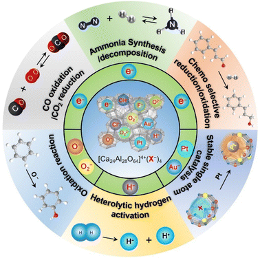
Porous materials have attracted great attention over the last two decades owing to their technological applications in many fields.1 They are generally used as catalysts,2 adsorbents,3 and biomaterials4 owing to their ordered structure arrangement and multiscale pore size distribution. According to the International Union of Pure and Applied Chemistry (IUPAC) definition, porous materials can be classified into three categories based on their pore size distribution: microporous, mesoporous, and macroporous. Compared with mesoporous and macroporous, microporous materials often possess interconnected pores of less than 2 nm in size with large surface areas of 300–2000 m2 g−1. Typically, zeolites,5 metal organic frameworks (MOFs),6 and carbon7 are the most well-known group of microporous materials, in which the unique microporous or cage structure can trap different kinds of molecules and ions. The trapped chemical species enable selective chemical reactions on the surface of the pores, which are believed to be catalytic active sites. When the pore size is reduced to extremely small, the encaged species can be regarded as a quantum dot with the emergence of a quantum effect.8 Thus, various novel functions are expected to be achieved over microporous materials owing to the low-dimensional nature of their caged state.12CaO·7Al2O3 (C12A7) is a new type of nanoporous material in which the nanoporous framework is positively charged, and thus anions and/or electrons can be encapsulated therein.9 This nanoporous material differs completely from traditional microporous materials in which positively charged or neutral species are entrapped in the porous structures. In other words, C12A7 has unique features among porous materials: a positively charged framework comprises 12 sub-nano-cages that are closely packed and share common planes as openings. Because the size of the positively charged cage is comparable to those of the conventional anions, various anions, such as e−,10 O2−,11 O−,12 H−,13 OH−,14 NH2−,15 S2−,16 Au−,17 F−,18 Cl−,19 and CN−,20 can be easily entrapped therein, as shown in Scheme 1. The exchangeability of the incorporated anions thus provides a convenient means of fine-tuning the selectivity of C12A7.
Because the crystal structure of C12A7 comprises three dimensionally connected sub-nano-cages with an open mouth of the cage at the surface, the substituted anions possibly interacted with each other or transferred to the surface through a monolayered oxide cage wall.9 These behaviors of the entrapped anions result in various novel properties, including ionic conductivity,21–24 electron conductivity10,25 and superconductivity.26–29 Accordingly, various physical and electronic device applications are achieved, including ionic conductors, cold electron emitters30–33 and anion emissions.18,19,34 For example, as the strongest oxidant among active oxygen species, the O− ion can be extracted from the cage into an external vacuum by applying an electric field with thermal assistance, generating a high-density O− beam in the order of μA cm−2.34 The introduction of functional anions in the matrix of C12A7 undoubtedly significantly improved its performance and expanded its applications.
Recently, the increase in publications on C12A7 as heterogeneous catalysis suggests that the field of C12A7-mediated chemical transformations is emerging and will establish a new area of research owing to their high activity associated with structural properties. In this review, we summarize the research progress on active anion-bearing C12A7-mediated chemical reactions in the last two decades and attempt to introduce some common practices in catalyst design. A brief introduction to the preparation methods for various active anions embedded in C12A7 is first introduced in each section. Then, we discuss the functions of the embedded anions in the chemical reactions and systematically explain the relationship between the material structure and the chemical properties of C12A7. Finally, a brief discussion is described on the further challenges and perspectives of C12A7 materials as well as its potential applications in the future.
2. Active ions substituted in C12A7 and its chemical applications
Since the discovery of the first air and room temperature stable electride [Ca24Al28O64]4+(e−)4 (C12A7:e−) in 2003,10 the research interest in [Ca24Al28O64]4+(X−)4 has increased rapidly, especially focusing on the functional application in chemical transformations. In the last two decades, different active anions (X = e−,10 O−,12 O2−,11 H−,35 Au−17 and Pt36) embedded in C12A7 have been widely reported in a series of significant chemical reactions, including ammonia synthesis/decomposition, CO2 reduction/CO oxidation, chemoselective reduction/oxidation and heterolytic hydrogen activation (Scheme 2).2.1. Electron-substituted C12A7
In C12A7, an extreme case is the total replacement of free O2− ions with anionic electrons, forming the conductive electride material C12A7:e−.10 The most characteristic feature of the C12A7:e− electride is its low work function (2.4 eV),37 comparable to that of alkali metals, but with higher chemical inertness, which makes this material a promising electron donor in chemical reactions. In this section, we first introduce the preparation methods of C12A7:e− and then discuss their functional applications.| Process | Precursor | Reacting process | N e (cm−3) | |
|---|---|---|---|---|
| Physical process | UV illumination38 | Single crystal | H− (cage) → e− (cage) + H0 (cage) | 2 × 10¹⁹ |
| Ion implantation39 | Thin film | O2− (cage) → 2e− (cage) + 1/2O2 (gas) | 1.4 × 10²¹ | |
| Chemical process (reduction reaction) | Ca vapor treatment10 | Single crystal | O2− (cage) + Ca → 2e− (cage) + CaO | 2.3 × 10²¹ |
| Ti vapor treatment25 | Single crystal | O2− (cage) + Ti → 2e− (cage) + TiO2−x | 2.3 × 10²¹ | |
| CO gas40 | Single crystal/powder/thin film | O2− (cage) + CO → 2e− (cage) + CO2 | 8 × 10¹⁹ | |
| Melt solidification | No specific one | C22− (cage) →2e− (cage) + 2C or C22− (cage) + 2O2− → 6e− (cage) + 2CO | 9 × 10¹⁹ | |
| Glass-ceramics41 | No specific one | 9 × 10¹⁹ |
In 2002, Hayashi et al. reported that the irradiation of hydride ions (H−) incorporated in C12A7:H− with ultraviolet light results in a conductive state that persists after irradiation ceases.38 The photo-activated C12A7:H− exhibits moderate electrical conductivity (∼0.3 S cm−1) at room temperature. The proposed transformation process can be expressed as follows: H− (cage) → e− (cage) + H0 (cage). The positively charged cage electrostatically captures the photo-ionized electron and forms an F+-like center. The electron concentration (Ne) determined by EPR (electron paramagnetic resonance) was 2 × 1019 cm−3. Because the electron is weakly bound in the cage, the wavefunction spreads spatially. Consequently, electrons could migrate throughout the framework by variable-range hopping.
The reduction in C12A7 is also achieved by ion implantation, one of the non-equilibrium physical processes in which a high concentration of ions can be introduced in a designated small area with excellent controllability. It is widely used for the modification of thin film materials. Miyakawa et al. conducted Ar+ ion implantation in polycrystalline C12A7 thin films and found that the free O2− ions could be removed from the cage by the collision of O2− ions and Ar+ ions, thus leaving free e− therein.39 The produced electrons by Ar+-implantation could be expressed using the following equation: O2− (cage) → 2e− (cage) + 1/2O2 (gas). Using this method, the Ne of the final obtained C12A7:e− can reach ∼1.4 × 1021 cm−3. It is noteworthy that ion implantation technology enables a higher Ne than that of UV irradiation with a designated narrow space.
Compared with physical processes, the types of C12A7 reduction reactions are more abundant in chemical processes. In 2003, Matsuishi et al. removed ∼100% of clathrated O2− ions from C12A7 by the thermal treatment of C12A7 singe crystal under Ca metal vapor.10 Single crystal C12A7 and Ca metal are sealed in a vacuum silica glass tube (∼10−3 torr) and treated at 700 °C (Fig. 1a). The heating process ensures that Ca metal volatilizes into vapor and reacts with the free O2− ions of C12A7 to form CaO, which was subsequently removed by mechanical polishing. The formation mechanism for the C12A7:e− can be expressed as follows: O2− (cage) + Ca → 2e− (cage) + CaO. With the extension of the Ca vapor treatment time, the color of the sample changes from transparent to green and, finally, to black with the Ne reaching up to 2 × 1021 cm−3 (Fig. 1b). It is noteworthy that the Ca treatment requires a long duration (240 hours for a 0.4 mm thin single crystal) to extract the total free O2− ions because the heating temperature is limited to 700 °C at maximum, preventing the reaction of C12A7 crystal and Ca to form Ca3Al2O6 (C3A). The surface generation of dense CaO film also hinders the deep reduction of bulk C12A7. Further, the replacement of free O2− ions is incomplete owing to the formation of a surface CaO layer that acts as a diffusion barrier.
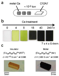 | ||
| Fig. 1 (a) Schematic illustration of the synthesis process for C12A7 electride via Ca treatment. (b) The Ca treatment changes the sample color from colorless to green and, finally, to black, with increasing duration of the Ca treatment. Copyright 2007, Springer Nature. (c) The Ti treatment changes the sample color from orange to black. The orange colour comes from Ir4+ dissolved from the Ir crucible used for single crystal growth.46 Copyright 2007, American Chemical Society. | ||
The above drawbacks were overcome by employing Ti metal vapor treatment. Ti could form stable nonstoichiometric oxides over a wide chemical composition range (1 < x < 2 in TiO2−x), and these Ti sub-oxides exhibit metallic conductivity. The outward diffusion of free O2− ions of C12A7 cannot be blocked even if a thick titanium oxide layer completely covers the sample surface. Additionally, high temperatures up to ∼1300 °C can be used for the calcination reduction process because Ti metal does not react with C12A7 up to this temperature. Kim et al. reported the treatment of C12A7 single crystals by Ti metal vapor at ∼1100 °C.25 The change in color from transparent orange tint to black indicates an increased electron concentration and enhanced electrical conductivity (Fig. 1c). Owing to the high reaction temperature, the diffusion rate of O2− in C12A7 increases by several orders of magnitude, resulting in the effective shortening of the heating time. Accordingly, Ne reaches the theoretical maximum value of ∼2.3 × 1021 cm−3.
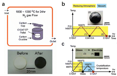
In addition to Ca and Ti metal vapor, the treatment of C12A7 in reducing atmospheres of CO/CO2 has also been investigated. Kim et al. placed a C12A7 sample in a carbon crucible with a cap heated at 1000–1300 °C for 24 h in a flowing N2 atmosphere (Fig. 2a).40 The atmosphere inside the carbon crucible during the treatment is strongly reductive CO/CO2 with a pO2 of 10−19–10−17 atm. Under this condition, CO gas reacts with free O2− ions of C12A7 to generate CO2, and then the electrons are injected into the cages to compensate for the positively charged lattice framework. The reduction process can be expressed as the following equation: O2− (cage) + CO (gas) → 2e− (cage) + CO2 (gas). The color of the sample becomes dark green because of the relatively low Ne of 8 × 1019 cm−3. Unlike metal vapour treatment, which inevitably produces the metal oxide layer at the surface, the sample surface remains clean without forming any additional impurities during the reaction. Hence, this reduction strategy can be applied to C12A7 with different sample forms (single crystals, powder and thin films).
A simple and efficient synthesis method of C12A7:e− is vital for practical applications. Kim et al. reported facile preparation of C12A7:e− electride from its melting and glass states in a carbon crucible with a carbon cap at 1600 °C (Fig. 2b and c).41 This high temperature produces a strongly reducing atmosphere inside the crucible with partial oxygen pressure as low as 10−16 atm. It is found that C22− ions dissolved into the melt from the carbon crucible to compensate for the oxygen deficiency arising from the strongly reducing atmosphere. Because of the similar anion sizes of C22− (1.2 Å) and O2− (1.4 Å), the C22− anion can operate as a template under a reducing atmosphere. The possible reaction mechanism can be expressed as follows: C22− (melt or glass) → C22− (cage) + O2− (cage) → 4e− (cage) + 2C or C22− (cage) + 2O2− (cage) → 6e− (cage) + 2CO (gas). The resultant crystallized C12A7:e− is dark green, which suggests a mediate electronic conductivity and that the Ne can reach 9 × 1019 cm−3.
The metal–insulator transition of [Ca24Al28O64]4+(O2−)2−x(e−)2x occurs at Ne ≈ 1 × 1021 cm−3, which is the prerequisite for the high electron donation ability of C12A7:e−. Matsuishi et al. reported a direct synthesis method for the preparation of C12A7:e− powder with an electron density up to a theoretical maximum of 2.33 × 1021 cm−3.42 C12A7:e− powder was synthesized by a reaction of C12A7, CaO·Al2O3 (CA), and Ca metal at 700–1100 °C: 0.8Ca12Al14O33 + 1.4CaAl2O4 + Ca → 1/2[Ca24Al28O64]4+(e−)4. This process comprises the following seven-step procedure. First, a mixture of C12A7 and CA was prepared by a reaction of CaCO3 and γ-Al2O3 with a molar ratio of 11![[thin space (1/6-em)]](https://www.rsc.org/images/entities/char_2009.gif) :
:![[thin space (1/6-em)]](https://www.rsc.org/images/entities/char_2009.gif) 7 at 1300 °C in ambient air: 11CaCO3 + 7Al2O3 → 0.8Ca12Al14O33 + 1.4CaAl2O4 + 11CO2↑(i). The sintered mixture (C12A7 + CA) was ball-milled (ii), and subsequently degassed at 700 °C for 2 h in the air (iii). After that, the mixture was heated at 1100 °C for 15 h in a dynamically evacuated silica tube (∼1 × 10⁻⁴ Pa) (iv). The C12A7 + CA and Ca metal shots were sealed in an evacuated silica tube and heated at 700 °C for 15 h (v). The tube was then opened in an Ar-filled groove box, and the obtained material was ground to spread Ca within the mixture (vi). Finally, the mixture was squeezed into a single-ended silica tube, which was subsequently evacuated and sealed. The tube was sealed in another evacuated silica tube. The doubly sealed tube was then heated at 1100 °C for 2 h (vii). This method involves multiple steps, such as crystallization of the mixture precursor of C12A7 and CA, strict evacuation, and encapsulation.
7 at 1300 °C in ambient air: 11CaCO3 + 7Al2O3 → 0.8Ca12Al14O33 + 1.4CaAl2O4 + 11CO2↑(i). The sintered mixture (C12A7 + CA) was ball-milled (ii), and subsequently degassed at 700 °C for 2 h in the air (iii). After that, the mixture was heated at 1100 °C for 15 h in a dynamically evacuated silica tube (∼1 × 10⁻⁴ Pa) (iv). The C12A7 + CA and Ca metal shots were sealed in an evacuated silica tube and heated at 700 °C for 15 h (v). The tube was then opened in an Ar-filled groove box, and the obtained material was ground to spread Ca within the mixture (vi). Finally, the mixture was squeezed into a single-ended silica tube, which was subsequently evacuated and sealed. The tube was sealed in another evacuated silica tube. The doubly sealed tube was then heated at 1100 °C for 2 h (vii). This method involves multiple steps, such as crystallization of the mixture precursor of C12A7 and CA, strict evacuation, and encapsulation.
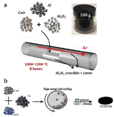
Jiang et al. reported a facile one-step and scalable aluminothermic synthesis method of C12A7:e− with Ne up to 1.23 × 1021 cm−3 (Fig. 3a).43 A mixture of CaO, Al2O3, and Al powders with molar ratios of 12![[thin space (1/6-em)]](https://www.rsc.org/images/entities/char_2009.gif) :
:![[thin space (1/6-em)]](https://www.rsc.org/images/entities/char_2009.gif) 7(1 − x):14(x) and x = 0–25% was placed in an alumina crucible with an alumina plate cover. Next, it was calcined in a horizontal tube furnace at 1000–1300 °C for 8 h in a flowing Ar atmosphere. After that, Li et al. reported another direct and efficient route to fabricate C12A7:e− from the raw materials of CaO, Al2O3 and Ca powders (Fig. 3b).44 The powders of CaO, Al2O3 and Ca with mole ratios of (12 − x):7
7(1 − x):14(x) and x = 0–25% was placed in an alumina crucible with an alumina plate cover. Next, it was calcined in a horizontal tube furnace at 1000–1300 °C for 8 h in a flowing Ar atmosphere. After that, Li et al. reported another direct and efficient route to fabricate C12A7:e− from the raw materials of CaO, Al2O3 and Ca powders (Fig. 3b).44 The powders of CaO, Al2O3 and Ca with mole ratios of (12 − x):7![[thin space (1/6-em)]](https://www.rsc.org/images/entities/char_2009.gif) :
:![[thin space (1/6-em)]](https://www.rsc.org/images/entities/char_2009.gif) x with x = 0–1.6 were mixed by a mechanical ball mill under an inert atmosphere. The mixed powders were placed into a ceramic die and sintered at 1000–1200 °C for 20 minutes in a 10−2 Pa vacuum under a uniaxial pressure of 60 MPa using the SPS system, and the Ne of the obtained C12A7:e− reaches 2 × 1021 cm−3. Moreover, Xiao et al. mixed stoichiometric C12H10Ca3O14 (calcium citrate) and Al2O3 powder into a graphite mold and then placed it into an SPS sintering system at 1000 °C for 5 minutes. A self-reduction process is achieved by in situ formed CO gas inside the graphite mold, avoiding the generation of impurities and simplifying the synthesis process. The Ne of the obtained C12A7:e− reaches 2 × 1021 cm−3.45
x with x = 0–1.6 were mixed by a mechanical ball mill under an inert atmosphere. The mixed powders were placed into a ceramic die and sintered at 1000–1200 °C for 20 minutes in a 10−2 Pa vacuum under a uniaxial pressure of 60 MPa using the SPS system, and the Ne of the obtained C12A7:e− reaches 2 × 1021 cm−3. Moreover, Xiao et al. mixed stoichiometric C12H10Ca3O14 (calcium citrate) and Al2O3 powder into a graphite mold and then placed it into an SPS sintering system at 1000 °C for 5 minutes. A self-reduction process is achieved by in situ formed CO gas inside the graphite mold, avoiding the generation of impurities and simplifying the synthesis process. The Ne of the obtained C12A7:e− reaches 2 × 1021 cm−3.45
2.1.2.1 Ammonia synthesis/decomposition. Ammonia synthesis from N2 and H2 is regarded as one of the most important catalytic reactions because NH3 is widely used for the production of synthetic fertilizers and chemical raw materials in the industry. Owing to the extremely large bond energy of N
![[triple bond, length as m-dash]](https://www.rsc.org/images/entities/char_e002.gif) N bond, industrial ammonia synthesis of the Haber–Bosch process with iron-based catalysts requires high temperature (673–873 K) and high pressure (20–40 MPa).47 For transition metal catalysts, N2 is fixed to the metal through σ bond donation, and then adsorbed N2 also accepts electrons to its antibonding orbitals by π backdonation. This electron acceptance process can be enhanced by electron donors, which promotes the weakening of the N
N bond, industrial ammonia synthesis of the Haber–Bosch process with iron-based catalysts requires high temperature (673–873 K) and high pressure (20–40 MPa).47 For transition metal catalysts, N2 is fixed to the metal through σ bond donation, and then adsorbed N2 also accepts electrons to its antibonding orbitals by π backdonation. This electron acceptance process can be enhanced by electron donors, which promotes the weakening of the N![[triple bond, length as m-dash]](https://www.rsc.org/images/entities/char_e002.gif) N bond.
N bond.
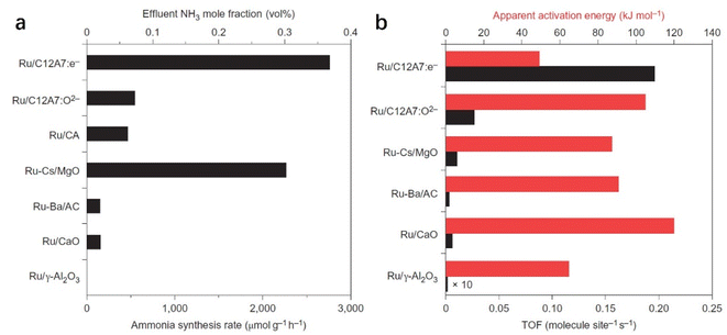
C12A7:e− comprises 3-dimensionally (3D) connected sub-nanometer-sized cages, in which anionic electrons are incorporated as counter anions. The 3D connection of these cages forms unique bands below the cage wall conduction band, called the cage conduction band (CCB).48 Because electrons are injected into this CCB, a low work function property emerges for C12A7:e− material.37 In this context, Kitano et al. reported that the C12A7:e− electride operates as an excellent electron donor to promote transition metal Ru in catalytic ammonia synthesis.49 Although the specific surface area of C12A7:e− is as low as 1–2 m2 g−1, Ru-loaded C12A7:e− catalysts exhibit a high NH3 synthesis rate of 8.2 mmol g−1 h−1, which is close to that of the bench-marked catalyst of Cs–Ru/MgO (Fig. 4a). Compared with other Ru-based catalysts, the extremely high turnover frequency (TOF) and relatively small activation energy indicate that C12A7:e− greatly contributed to promoting Ru metal for ammonia synthesis (Fig. 4b).
Because the catalytic performance of Ru/C12A7:e− strongly depends on the electron donation ability that stems from the unique electronic properties of C12A7:e−, Kanbara et al. prepared a series of C12A7:e− powders with controlled electron concentrations (Ne). The color of the samples was changed from white to green and black as Ne increased from 0 to 2.0 × 1021 cm−3. The reaction rate of ammonia synthesis over Ru/C12A7:e− obviously increased with Ne above 0.5 × 1021 cm−3 and reached a plateau at 1.0 × 1021 cm−3 (Fig. 5a).50 Interestingly, the correlation of the apparent activation energies (Ea) with Ne has a similar trend to the relationship between the ammonia formation rate and Ne, in which Ea of Ru/C12A7:e− with Ne above 1.0 × 1021 cm−3 is almost half that of the catalyst with Ne below 0.5 × 1021 cm−3 (Fig. 5b). The electronic structure of C12A7 with and without electrons is depicted in Fig. 5c. Under low Ne condition, the electron transfer from C12A7:e− to transition metal became difficult owing to the presence of an interfacial Schottky barrier, resulting in an inferior catalytic performance with significantly elevated Ea. The metal–insulator transition of C12A7:e− occurred at approximately 1.0 × 1021 cm−3, and the C12A7:e− with high Ne (2.3 × 1021 cm−3) showed high conductivity (1500 S cm−1)25 and low work function (2.4 eV).37 Accordingly, smooth electron injection occurs from C12A7:e− to Ru, which accounts for the low activation barrier of N2 dissociation.
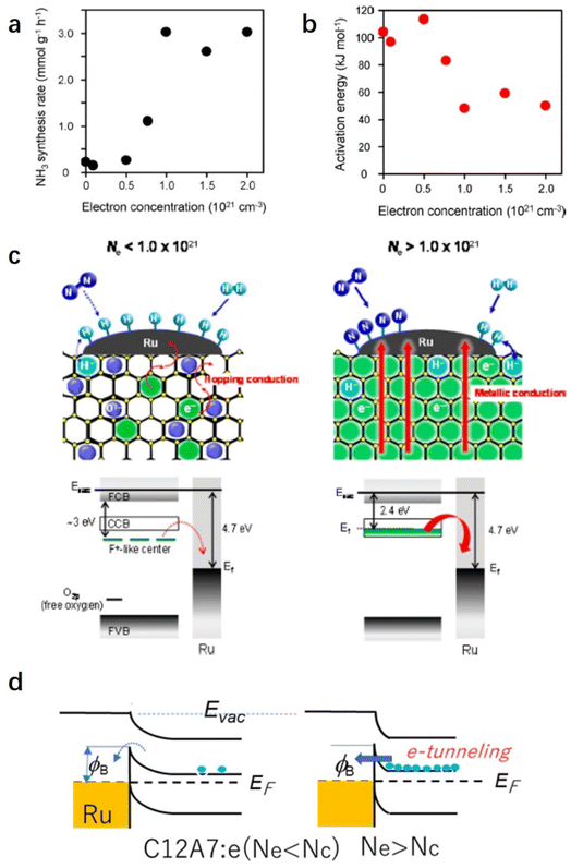 | ||
| Fig. 5 (a) Ammonia synthesis rate and (b) activation energy with Ru/C12A7:e− catalysts as a function of electron concentration. (c) Proposed reaction mechanism for ammonia synthesis over Ru/C12A7:e−. Copyright 2015, American Chemical Society. (d) Energy barrier at Ru/C12A7:e− interface. Because the work function (ϕ) of Ru is much higher than that of C12A7:e−, the contact with a Schottky barrier and a height of Δϕ is formed. When Ne is higher than Nc (critical concertation for metal–insulator transition), electrons can pass through this barrier by tunneling.51 Copyright 2021, Springer Nature. | ||
The electron-donation capability of C12A7:e− is experimentally evidenced by Fourier transform infrared (FT-IR) spectra of N2 adsorption. The vibrational peaks of N2 adsorption on Ru/C12A7:e− are observed at lower wavenumbers than those on Ru/C12A7:O2− and Ru/Al2O3 (Fig. 6a).49 This shift implies that the N![[triple bond, length as m-dash]](https://www.rsc.org/images/entities/char_e002.gif) N bond is significantly weakened by the donated electrons from C12A7:e− to the absorbed N2, resulting in a significantly suppressed energy barrier of N2 dissociation compared to other conventional Ru-loaded catalysts. It is also noted that such supported Ru metal is not subject to hydrogen poisoning owing to the hydrogen storage capacity of C12A7:e−. The C12A7:e− can capture hydrogen as H− ions in the cages through the reaction of electrons with the spillover of hydrogen from the Ru surface (H0 + e− → H−). The electrons are regenerated in the cages by releasing H atoms from the cages: H− (cage) → H0 (release from the cage) + e− (cage). This reversible e−–H− exchange reaction in Ru/C12A7:e− effectively prevents hydrogen poisoning on the Ru surface, which is also confirmed by temperature-programmed absorption (TPA). Ru/CaO·Al2O3 without a positively charged nanocage structure cannot absorb hydrogen, while Ru/C12A7:O2− and Ru/C12A7:e− store hydrogen at 350–600 °C, and the hydrogen storage ability of Ru/C12A7:e− is about 4 times higher compared to that of Ru/C12A7:O2− (Fig. 6b).52 Temperature-programmed desorption of H2 (H2-TPD) of these catalysts after ammonia synthesis demonstrates that only Ru/C12A7:e− shows a clear peak for H2 desorption at 300–500 °C (Fig. 6c), which indicates reversible e−–H− exchange during ammonia synthesis.
N bond is significantly weakened by the donated electrons from C12A7:e− to the absorbed N2, resulting in a significantly suppressed energy barrier of N2 dissociation compared to other conventional Ru-loaded catalysts. It is also noted that such supported Ru metal is not subject to hydrogen poisoning owing to the hydrogen storage capacity of C12A7:e−. The C12A7:e− can capture hydrogen as H− ions in the cages through the reaction of electrons with the spillover of hydrogen from the Ru surface (H0 + e− → H−). The electrons are regenerated in the cages by releasing H atoms from the cages: H− (cage) → H0 (release from the cage) + e− (cage). This reversible e−–H− exchange reaction in Ru/C12A7:e− effectively prevents hydrogen poisoning on the Ru surface, which is also confirmed by temperature-programmed absorption (TPA). Ru/CaO·Al2O3 without a positively charged nanocage structure cannot absorb hydrogen, while Ru/C12A7:O2− and Ru/C12A7:e− store hydrogen at 350–600 °C, and the hydrogen storage ability of Ru/C12A7:e− is about 4 times higher compared to that of Ru/C12A7:O2− (Fig. 6b).52 Temperature-programmed desorption of H2 (H2-TPD) of these catalysts after ammonia synthesis demonstrates that only Ru/C12A7:e− shows a clear peak for H2 desorption at 300–500 °C (Fig. 6c), which indicates reversible e−–H− exchange during ammonia synthesis.
The difference in the reaction mechanism of NH3 synthesis between Ru/C12A7:e− and conventional catalysts is illustrated in Fig. 7.52 In conventional catalysts, N2 and H2 molecules are dissociated on the surface of transition metal through a Langmuir–Hinshelwood mechanism, where the energy barrier of N2 dissociation (Edis) is the highest among all elementary steps. Therefore, the N2 cleavage is regarded as the rate-determining step (RDS) (Fig. 7a). In contrast, the NH3 synthesis rate of Ru/C12A7:e− is not limited by this step because of the enhanced N2 dissociation on Ru facilitated by electron injection from C12A7:e−. Accordingly, the RDS shifted from N2 dissociation to the formation of N–Hn species (Fig. 7b).
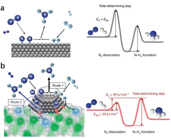 | ||
| Fig. 7 Reaction mechanism and energy diagram for NH3 synthesis on (a) conventional catalyst and (b) Ru/C12A7:e− catalyst. Copyright 2015, Springer Nature. | ||
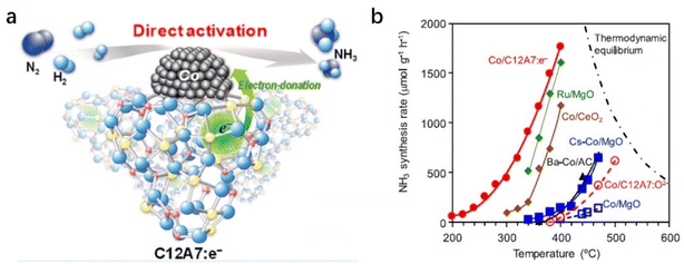
The C12A7:e− support can also boost NH3 synthesis over the cobalt (Co) catalyst (Fig. 8a).53 According to the scaling relationship of NH3 synthesis proposed by Nørskov et al., Co metal is not considered an optimal metal for dissociative N2 adsorption.54 Generally, harsh reaction conditions are required for Co-based catalysts in NH3 synthesis, and the apparent activation energies are often as high as 90–110 kJ mol−1. In contrast, Co/C12A7:e− promotes the N2 activation with a low activation energy (ca. 50 kJ mol−1) even under relatively mild conditions, which is similar to those of state-of-the art Co catalysts, such as Co3Mo3N, LaCoSi, and Co–LiH (40–60 kJ mol−1). As shown in Fig. 8b, the activity of Co/MgO is unsatisfactory despite the addition of the Cs promoter. In sharp contrast to other oxide support materials, Co(2.6 wt%)/C12A7:e− exhibits high catalytic activity, and the reaction rate is an order of magnitude higher than the other Co catalysts. The initial temperature for NH3 generation over Co/C12A7:e− is ∼200 °C lower than that for the Co/C12A7:O2− catalyst. The high performance of the Co/C12A7:e− catalyst is attributed to the electron donation power of C12A7:e− with a low WF (2.4 eV), which enables N2 cleavage at Co metal at low temperatures. This study again emphasizes that electron injection from C12A7:e− plays an important role in the promotion of transition metals that catalyze ammonia synthesis.
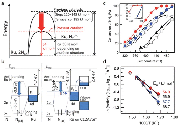
In the NH3 decomposition reaction, it is generally accepted that the RDS is the associative desorption of N adatoms from the metal surface. Hayashi et al. reported a facile NH3 decomposition on Ru-loaded C12A7:e− electride with a low activation energy (Fig. 9).55 They attributed the high catalytic performance of Ru/C12A7:e− to the low work function feature of C12A7:e− electride. On the traditional Ru surface, the 2p-orbital of N interacts with the d-orbital of Ru at the Fermi level (EF). The anti-bonding orbital (Ru–N* orbital) of the Ru–N bond is far away from EF (+3 eV), and the bond orbital is about 5.5 eV below EF. On the Ru/C12A7:e− surface, driven by the difference in the work function between Ru and C12A7:e−, the electrons in the CCB state of C12A7:e− can transfer to Ru, raising the EF of Ru metal relative to the N 2p orbitals. Consequently, in Ru/C12A7:e−, the state of the Ru–N* orbital becomes much closer to EF compared with that of bare Ru metal, enabling a favored electron injection into the Ru–N* orbital (Fig. 9b). Thus, the activation and cleavage of the Ru–N bond is significantly promoted over Ru/C12A7:e−, achieving efficient NH3 decomposition under mild conditions.
2.1.2.2 Selective hydrogenation of α, β-unsaturated aldehydes. Chemoselective hydrogenation is a powerful tool for achieving a controlled reduction in various organic compounds. Tuning the electronic structure of metal catalysts, also known as electronic metal–support interactions (EMSI), is considered an efficient strategy to improve catalytic performance.56 Because of the strong electron donation power of C12A7:e−, the electronic structure of the loaded active metal can be easily manipulated through the role of EMSI, thereby controlling the adsorption and activation of the substrates that determine the overall activity and selectivity.
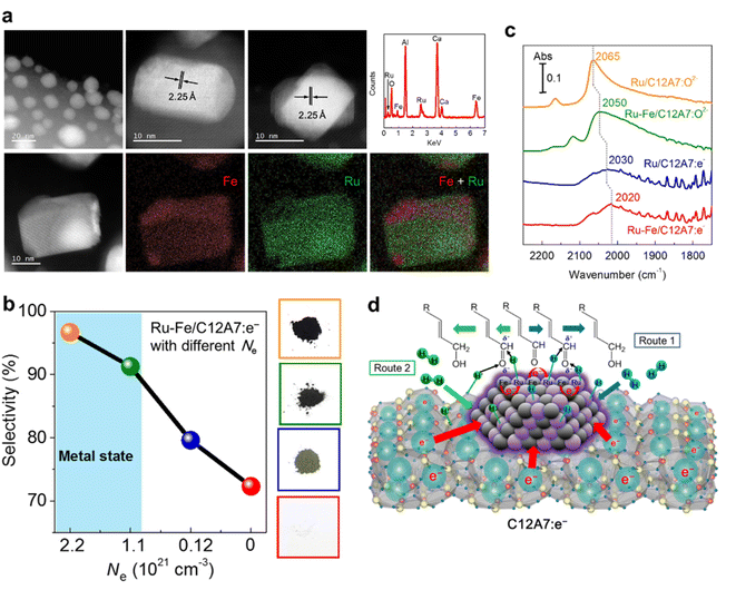
Our group reported that Ru–Fe alloy nanoparticles deposited on C12A7:e− electride enabled the highly efficient selective hydrogenation of α,β-unsaturated aldehydes.57 Ru–Fe alloys are formed on C12A7:e− surface, and both Fe and Ru are homogeneously distributed in the nanoparticles (Fig. 10a). For the hydrogenation of α,β-unsaturated aldehydes, high selectivity and activity of the unsaturated alcohol product is difficult to achieve because of the thermodynamically favored hydrogenation of the C![[double bond, length as m-dash]](https://www.rsc.org/images/entities/char_e001.gif) C bond. Thus, conventional hydrogenation catalysts of Pt, Pd, and Ru preferentially produce saturated aldehydes. In the C12A7:e− electride catalyst, the electronic nature of the Ru–Fe nanoparticles can be modified by the electron donation of C12A7:e−, leading to a remarkable increase in the selectivity of unsaturated alcohol. It is noted that the selectivity of unsaturated alcohol increases with the enhanced Ne of C12A7:e−, which suggests that the hydrogenation process strongly depends on the electronic properties of C12A7:e− support (Fig. 10b). The electron donation capabilities of C12A7:e− was confirmed by diffuse reflectance infrared Fourier transform (DRIFT) spectroscopy using CO as a probe molecule (Fig. 10c). Compared with the linear Ru0–CO (2050 cm−1) peak of Ru–Fe/C12A7:O2−, a clear redshift is identified in Ru–Fe/C12A7:e− (2020 cm−1), implying that the C
C bond. Thus, conventional hydrogenation catalysts of Pt, Pd, and Ru preferentially produce saturated aldehydes. In the C12A7:e− electride catalyst, the electronic nature of the Ru–Fe nanoparticles can be modified by the electron donation of C12A7:e−, leading to a remarkable increase in the selectivity of unsaturated alcohol. It is noted that the selectivity of unsaturated alcohol increases with the enhanced Ne of C12A7:e−, which suggests that the hydrogenation process strongly depends on the electronic properties of C12A7:e− support (Fig. 10b). The electron donation capabilities of C12A7:e− was confirmed by diffuse reflectance infrared Fourier transform (DRIFT) spectroscopy using CO as a probe molecule (Fig. 10c). Compared with the linear Ru0–CO (2050 cm−1) peak of Ru–Fe/C12A7:O2−, a clear redshift is identified in Ru–Fe/C12A7:e− (2020 cm−1), implying that the C![[triple bond, length as m-dash]](https://www.rsc.org/images/entities/char_e002.gif) O bond on Ru–Fe/C12A7:e− is weakened by electrons, which provides evidence for the strong electronic modification of C12A7:e− electride.
O bond on Ru–Fe/C12A7:e− is weakened by electrons, which provides evidence for the strong electronic modification of C12A7:e− electride.
The possible reaction mechanism of the selective hydrogenation process on Ru–Fe/C12A7:e− is shown in Fig. 10d. The electron-rich Ru–Fe surface repels the C![[double bond, length as m-dash]](https://www.rsc.org/images/entities/char_e001.gif) C bond via the repulsive interaction between metal d-orbitals and C
C bond via the repulsive interaction between metal d-orbitals and C![[double bond, length as m-dash]](https://www.rsc.org/images/entities/char_e001.gif) C bonds, favoring a vertical adsorption configuration via the C
C bonds, favoring a vertical adsorption configuration via the C![[double bond, length as m-dash]](https://www.rsc.org/images/entities/char_e001.gif) O bond. Moreover, the Fe site also operates as an electrophilic site, which enables the attraction of the C
O bond. Moreover, the Fe site also operates as an electrophilic site, which enables the attraction of the C![[double bond, length as m-dash]](https://www.rsc.org/images/entities/char_e001.gif) O bond via the lone electron pair of the oxygen atom, resulting in the weakening of the C
O bond via the lone electron pair of the oxygen atom, resulting in the weakening of the C![[double bond, length as m-dash]](https://www.rsc.org/images/entities/char_e001.gif) O bond. Therefore, the selective hydrogenation of C
O bond. Therefore, the selective hydrogenation of C![[double bond, length as m-dash]](https://www.rsc.org/images/entities/char_e001.gif) O bonds is preferred even in the presence of C
O bonds is preferred even in the presence of C![[double bond, length as m-dash]](https://www.rsc.org/images/entities/char_e001.gif) C bonds.
C bonds.
2.1.2.3 CO oxidation reaction. The investigation of C12A7:e− as an electron donor is mainly carried out in reductive atmospheres. Interestingly, C12A7:e− is stable in oxidative atmospheres up to 300 °C, which implies that C12A7:e− can also function as an electron donor under oxidative atmospheres below 300 °C.42 Therefore, Ru nanoparticles on C12A7:e− have higher oxidation resistance than those on conventional oxide supports.58 As expected, C12A7:e− supported Ru catalysts exhibited high and stable catalytic activity for CO oxidation reaction.59 It is generally accepted that O2 molecules are adsorbed on the support, such as Au/TiO2, and then the reaction proceeds through the lattice oxygen-mediated Mars–van Krevelen (MvK) mechanism.60 Additionally, CO oxidation can be promoted by the EMSI of the metal–support interface of the reducible oxide-supported metal catalysts.61
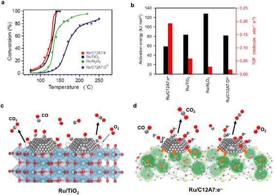
The CO oxidation reaction over Ru/C12A7:e− is initiated at ∼70 °C, which is obviously lower than that of Ru/C12A7:O2− (Fig. 11a).59 Ru/C12A7:e− shows similar catalytic activity to Ru/TiO2 but with much-suppressed activation energy (Ea) (Fig. 11b), and the CO conversion reached 100% at around 140 °C, even though with a smaller surface area of Ru/C12A7:e− (∼1 m2 g−1) compared with Ru/TiO2 (54 m2 g−1). The high catalytic performance of Ru/C12A7:e− is mainly attributed to the high electron donation power of the C12A7:e− support. As shown in Fig. 11c, reducible oxides, such as TiO2, rather than nonreducible supports (e.g., Al2O3), facilitate CO oxidation over the active transition metal, in which lattice oxygen near the metal is also involved in the formation of CO2 and is subsequently recovered by gas-phase O2 (MvK mechanism).60
However, CO oxidation over Ru/C12A7:e− does not proceed through the MvK mechanism because the framework oxygens are difficult to remove below 700 °C.10 As shown in Fig. 11d, CO and O2 molecules are adsorbed on the Ru surface, and O2 is immediately cleaved into oxygen adatoms. The rate-determining step of CO oxidation over Ru catalysts is well accepted as the formation of the CO–O bond.62 In C12A7:e− catalyst, the energy barrier of this step is significantly suppressed by the electride character as follows: the anionic electrons are injected from C12A7:e− to Ru, enabling the charge transfer from Ru d-orbitals to the 2π* antibonding orbitals of CO. Consequently, the C–O bond is weakened with the formation of Cδ+–Oδ− species. The electronic interaction between C12A7:e− and Ru also favors the generation of negatively charged O adatoms (Oδ− species). Hence, the association reaction of Cδ+–Oδ− and Oδ− species results in high catalytic activity for CO oxidation with low Ea.
2.1.2.4 Cross-coupling reactions. The cross-coupling reaction is one of the most practiced classes of catalytic C–C bond formation. Because of the high activation barriers of the substrates associated with the rate-limiting elementary step, most cross-coupling reactions, especially those run over heterogeneous Pd catalysts, strongly rely on electron-rich Pd active sites.63 C12A7:e− electride is an ideal support for achieving electron-rich Pd species because of its unique electronic properties associated with high carrier density and low work function (LWF). However, C12A7:e− cannot be applied to aqueous reactions owing to its water sensitivity. Moreover, the extremely low specific surface area of C12A7:e− restricts the dispersion of Pd metal.
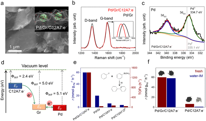
Recently, our group designed a multistep electron transfer process through an intermediate graphene layer over an electride composite material, Pd/Gr/C12A7:e−, in which nanometric Pd clusters were highly dispersed on graphene encapsulated C12A7:e− electride (Fig. 12a).64 The graphene layer serves as an excellent electron transport medium, promoting electron transfer from the internal C12A7:e− electride through external Pd active sites to the aryl halide substrates. The multistep electron transfer process on the Pd/Gr/C12A7:e− catalyst was supported by performing Raman and XPS experiments, in which a blue shift of the G-band of the Gr layer (Fig. 12b) as well as a lower energy shift of the Pd 3d peak (Fig. 12c) emerged after the addition of C12A7:e−. The electron transfer process is illustrated in Fig. 12d. C12A7:e− electride with a low work function (ΦWF = 2.4 eV) is considered an electron donor for Gr (ΦWF = 5.0 eV), leading to an electron transfer from C12A7:e− to Gr. Because of the comparable work functions of Gr (ΦWF = 5.0 eV) and Pd (ΦWF = 5.1 eV), the electron flows smoothly between Gr and Pd, allowing for negatively charged Pd species. Consequently, this composite material host has a strong electron donating ability associated with both highly dispersed and negatively charged Pd species, affording Suzuki cross-coupling reactions with over 20 times higher turnover frequencies and ∼30% reduced activation energies compared to previously studied Pd-based catalysts (Fig. 12e). Impressively, the catalyst can also trigger various carbon–carbon cross-coupling reactions, such as Suzuki, Sonogashira, Stille, Hiyama and Heck coupling, with high activities.
It has also been reported that the Gr layer protects C12A7:e− electride against water. A Suzuki coupling reaction was performed over Pd/Gr/C12A7:e− powder with and without water-impregnation. The reaction rate remained almost unchanged, and the black color of the sample also remained (Fig. 12f). In the absence of a protective layer of Gr, the catalytic activity of the Pd/C12A7:e− catalyst was obviously degraded after water impregnation, and the sample color became light grey, which is associated with the transformation of the related Ca and Al hydrates. Mechanistic studies have demonstrated that the highly negatively charged Pd sites induce electron injection into the antibonding orbitals of C-X (X = I, Br), thus promoting the activation of aryl halides with various coupling partners under mild conditions.
2.1.2.5 Electrochemical reactions. Because of its metallic nature and small work function properties, C12A7:e− is also used as a novel cathode material in important electrochemical reactions. Li et al. reported the electrochemical transformation of the hydroxylation of p-(methylthio)-phenylboronic acid into p-(methylthio)phenol using C12A7:e− as an electrode.65 Compared with traditional Pt and glassy carbon (GC) electrodes, the C12A7:e− electrode showed a significantly higher cathodic current for producing superoxide ions. Accordingly, the yield of p-(methylthio)phenol over the C12A7:e− electrode was as high as 90%, outperforming Pt (65%) and GC (79%) electrodes.
In addition to the hydroxylation of arylboronic acid, Li et al. also found that C12A7:e− electrode shows good affinity to CO2 and the inhibition of CO2 reduction, which is favored for the monocarboxylation of various olefins.66 In galvanostatic electrolysis under a CO2 atmosphere, the monocarboxylic products were obtained with a higher yield (91%) than those at Pt (9%) and GC (32%) electrodes. Cyclic voltammetric analysis, together with galvanostatic electrolysis, demonstrated that the olefin was first reduced at the cathode to generate radical anion and then reacted with adsorbed CO2 immediately to form the corresponding monocarboxylic products.
Regarding the applications of C12A7:e− in electrochemical transformations, researchers have recently turned their attention to the development of high-efficiency oxygen reduction reaction (ORR) electrocatalysts. Khan et al. developed Sn-doped C12A7:e− composite material and applied it to a highly active and durable electrocatalyst in the ORR.67 Both the onset potential and current density of Sn-doped C12A7:e− are similar to commercial Pt/C catalysts. Not limited to electrocatalysis, the application of C12A7:e− in the field of photocatalysis is also studied by Hu et al.68 They reported C12A7:e− as an electron promoter to P25 in a hydrogen evolution reaction (HER) from water through the photocatalysis process. The H2 production rate reached 663 μmol h−1 g−1, which was 43.9 times higher than that of pure P25. Mechanistic studies indicated that the introduction of C12A7:e− promoted the efficient separation of photogenerated electron–hole pairs of P25, resulting in the formation of a built-in electric field from P25 to C12A7:e− owing to the work function difference. The above electrocatalysis reactions are conducted in the aqueous phase. However, it is noteworthy that the crystal structure of C12A7:e− is not stable in water and slowly decomposes to form a Ca–Al–O–OH gel as an aluminous cement, leading to the release of anionic electrons. Therefore, we consider that the crystal and electronic structures of C12A7:e− after aqueous reactions should be identified carefully through detailed characterization.
Summarizing these encouraging advances, one may perceive that for C12A7:e−-based catalysts, the electronic structure modification of the loaded active metal via strong electron donation power of C12A7:e− support creates a scenario to alter the bonding geometry and electronic nature of the reacting species, which is critical for the improvement of both activity and selectivity of heterogeneous metal-loaded catalysis.
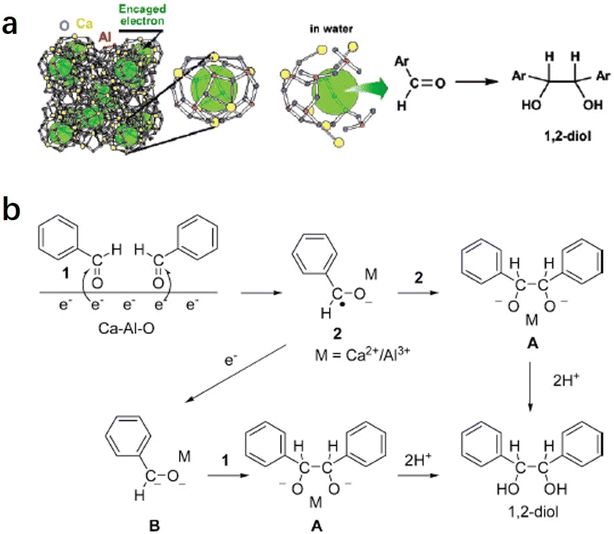
2.1.3.1 Pinacol coupling reaction of aldehydes. In an aqueous medium, electrons are released from C12A7:e− electride by the decomposition of the Ca–Al–O framework in solution. Thus, C12A7:e− electride can be viewed as a solid form of solvated electrons. It can not only be used as an efficient support in catalysis, but the electrons of its framework can also operate as a reducing reagent in organic synthesis. In 2007, Buchammagari et al. first used C12A7:e− as a reductive reagent for the pinacol coupling of aromatic aldehydes.69 When C12A7:e− and benzaldehyde are mixed in water, C12A7:e− electride gradually dissolves, and the black powder transforms into a white gel. The white gel is hydrolyzed by hydrochloric acid aqueous solution and then extracted with Et2O to produce 1,2-diphenylethyleneglycol (Fig. 13a).
After the reaction with water, a gel layer is formed on the surface of C12A7:e−, which is similar to the hydrolysis of aluminous cement. A plausible mechanism for the pinacol coupling promoted by the C12A7:e− is shown in Fig. 13b. The carbonyl group of the aldehyde accepts the electrons released from the decomposed C12A7:e−. The formed anion radicals are concentrated at the surface and coordinated to the surface Ca2+ or Al3+ cations (2). After that, two coordinated anion radicals undergo a dimerization reaction to form a pinacolate dianion (A). The dimerization of the anion radical coordinated with the metal forms the pinacolate dianion (A). Moreover, dianion (B) may also be formed by the one-electron reduction of (2). A nucleophilic addition of dianion (B) to the carbonyl group of aldehydes also yields A. Both pathways enable the formation of C–C bonds in the pinacol coupling reactions.
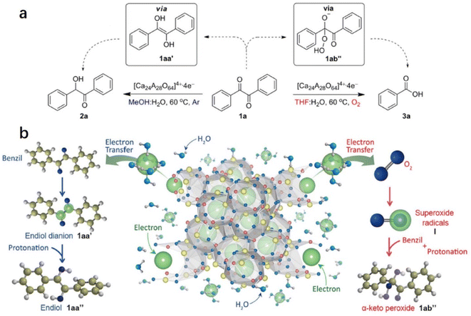
2.1.3.2 Reduction and oxidation of ketones. Inspired by the water-mediated pinacol coupling reaction over C12A7:e−, Kim et al. reported the utilization of C12A7:e− electride as an electron source for the chemoselective oxidation and reduction of ketones in water (Fig. 14a).70 The selectivity of the reaction can be controlled by the radical species of the transient intermediates. This controlled process is achieved by the reaction of the electrons of C12A7:e− with diketone or O2, which leads to the formation of ketene dianions and superoxide radicals, respectively. Water plays two important roles in chemoselective reactions: one is the release of anionic electrons by reacting with C12A7:e−, and the other is the electron solvation by water molecules mediated by transferring the anionic electrons to the substrates. The evolution of hydrogen gas demonstrated water splitting by electrons. Then, chemoselective reduction and oxidation are controlled by the electron transfer pathway.
As shown in Fig. 14b, in the reduction reaction, 1,2-diketone accepted two electrons from the solvated electron by water. After that, the two ketyl radical anions of 1,2-diketone quickly convert to enediol dianions via a radical dimerization process. The enediol dianion is protonated by a protic solvent, subsequently forming an enediol intermediate that undergoes tautomerization to generate α-hydroxy ketone. In the oxidation reaction, the electrons are first transferred to the oxygen molecule to facilitate the formation of superoxide radicals. These superoxide radical anions then react with benzil, resulting in the formation of α-peroxy ketone intermediate. It is also proposed that the utilization of electrides may be an alternative to the pulse radiolysis of water in synthetic chemistry.
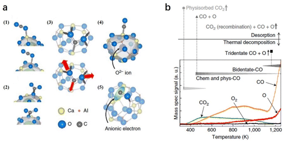
2.1.3.3 CO2 reduction. Because CO2 is an important greenhouse gas, the conversion of CO2 into useful chemicals, such as CO, provides a highly promising way for sustainable development. Because of the nonpolar and linear double bonds of CO2 molecules, the activation of CO2 normally requires either harsh conditions or active reducing agents. Toda et al. reported that CO2 can be split by C12A7:e− at room temperature, in which a high concentration of localized electrons in the near-surface region and a corrugation of the C12A7 surface can trap O atoms as well as strain CO and CO2 molecules.71
On C12A7:e− surface, the cage structures are occupied by anionic electrons, which also serve as anchor sites for trapping CO2 and CO. Because the surface of C12A7 is corrugated, there are five possible configurations of the molecule adsorption: (1) physisorbed CO2, (2) bent CO2δ−, (3) tridentate CO2 and (4, 5) dissociated CO + O (Fig. 15a). In the TPD measurement (Fig. 15b), physisorbed CO2 and CO started to desorb at 350 and 400 K, respectively. At temperatures above 400 K, a small amount of CO2 desorption stemmed from partial CO and O recombination. Moreover, this recombination is restrained above 700 K owing to O atom desorption. At temperatures above 1100 K, the total physisorbed CO2 and most of the CO leave the surface. Additionally, the deep trapped CO2 (tridentate configuration) is decomposed, causing a rapid increase in CO and O desorption. Because reductive species, such as metallic alkali or alkaline earth metals or harsh reaction conditions, are not required, C12A7:e− is considered a promising reducing agent for CO2 activation and splitting.
2.2. O− and O2− substitution
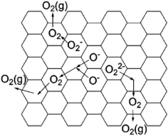
Oxygen usually exists as a divalent anion O2− in oxide crystals. There are a few cases where oxygen forms active species, such as O−, O2−, and O22−, because these active oxygen species are highly unstable and difficult to obtain in large quantities, especially for O− with extremely strong oxidation power.70,72 If a material can store a large amount of active oxygen species in a chemically and thermally stable form, it is expected to exhibit unique chemical properties. C12A7 has a positively charged framework [Ca24Al28O64]4+ that possesses 12 interconnected nanocages with a diameter of ca. 0.4 nm, providing opportunities to store various anions. Normally, O2− counter anions occupy the cages of C12A7 (C12A7:O2−).9 These encaged O2− can be substituted by active oxygen species (O− and O2−), resulting in stable storage of these active oxygen species in the cage of the C12A7. Thus, it is anticipated that the obtained C12A7:O− and C12A7:O2− exhibit great performance in some important chemical reactions.| O2 (atmosphere) → O2 (cage) |
| O2− (cage) + O2 (cage) → O− (cage) + O2− (cage) |
Matsuishi et al. observed the hyperfine splitting of O2− in a C12A7 single crystal with the treatment of 17O2 at 550 °C, providing solid evidence that encaged O2− derived from gaseous O2 in the atmosphere.77
Yang et al. studied the formation mechanism of active oxygen species in C12A7, including O−, O2−, and O22−.75 For O22−, it may be formed via the reaction of O2 with the engaged free oxygen:
| 2O2− (cage) + O2 (cage) → 2O22− (cage) |
| 2O− (cage) → O22− (cage) |
These oxygen species in C12A7 become mobile and can be desorbed at above 600 °C. When heating C12A7 in O2 at temperatures higher than 400 °C, these oxygen species can also be regenerated. The desorption of oxygen species occurs in a manner that reverses the formation processes (Fig. 16).
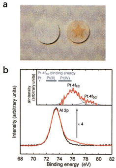
2.2.2.1 Super oxidative property. Hayashi et al. reported that the O−-encaged C12A7 exhibits superior oxidative reactivity, which can even oxidize the precious metal Pt.12 As shown in Fig. 17a, O−-encaged C12A7 was attached to a plate of Pt metal, and the plate was annealed at 1350 °C in wet and dry oxygen (Fig. 17a). The O−-encaged C12A7 contacted area became brown in dry oxygen, while the wet oxygen treated one remained colorless. The subsequent XPS characterization verified the presence of the tetravalent state of Pt(VI) (Fig. 17b), indicating that Pt metal could be oxidized by oxygen radicals embedded in C12A7 during dry oxygen treatment.
2.2.2.2 Partial oxidation of methane. Owing to the increasing awareness of human environmental protection, clean energy, such as hydrogen, is urgently needed. The partial oxidation of methane is regarded as a potential route to obtaining hydrogen.79–81 Compared with methane reformed by steam and CO2, methane oxidation reaction is thermodynamically much favored. Moreover, the ratio of the product, which is 2
![[thin space (1/6-em)]](https://www.rsc.org/images/entities/char_2009.gif) :
:![[thin space (1/6-em)]](https://www.rsc.org/images/entities/char_2009.gif) 1 for H2 and CO, exactly matches the feed ratio for Fischer–Tropsch syntheses (Fig. 18a).82 The high oxidative properties and controlled oxygen radicals offer C12A7 a special ability for the oxidation of methane.
1 for H2 and CO, exactly matches the feed ratio for Fischer–Tropsch syntheses (Fig. 18a).82 The high oxidative properties and controlled oxygen radicals offer C12A7 a special ability for the oxidation of methane.
In 2004, Yang et al. reported various transition metals, such as Ni, Co, Pt, Pd and Ru, supported C12A7 are efficient in the partial oxidation of methane.83 Through the investigation of the metal type, reaction temperature and space velocity, Pt/C12A7 and Ni/C12A7 are the optimal catalysts for the reaction, which offered a relatively high selectivity and stability even under mild conditions (Fig. 18b–d). They attributed the counterintuitive high activity of the C12A7 catalyst to two factors: (1) the unique surface cages of C12A7 allow for high dispersion of metal; (2) the active oxygen species of C12A7 ensure a high coke resistance ability.
2.2.2.3 Steam reforming of bio-oil. Hydrogen is regarded as an ideal green energy carrier, and the main route of hydrogen products is the catalytic steam reforming of fossil fuels, such as natural gas, oil-derived naphtha, partial oxidation of heavy oils, and coal gasification.84–86 The production of a large amount of carbon dioxide causes serious environmental issues. The development of clean alternatives to produce hydrogen has attracted considerable attention. As an environmental and renewable source, biomass is widely accepted as a promising raw material for hydrogen production.87,88 The most efficient route for the generation of hydrogen from biomass should be catalytic steam reforming of bio-oil with the combination of a water gas shift reaction (Fig. 19a).89
Wang et al. reported a group of early transition metals supported C12A7:O− catalysts (C12A7:O−/M, M = Mg, K, and Ce), which can be employed to promote hydrogen production from bio-oil.90 Based on the detailed investigation of the loaded metal types and reaction conditions, it is found that the hydrogen yield over the C12A7:O−/18% Mg catalyst was as high as 80% with a carbon conversion of nearly 100% (Fig. 19b and c). They attributed the high catalytic performance of C12A7:O−/18% Mg to the incorporated O− species, in which O− promotes the formation of OH− and effectively suppresses carbon deposition.
2.2.2.4 Formation of phenol. As one of the most important chemical raw materials, the annual global demand for phenol is approximately 10 million tons. Generally, a multi-stage cumene process is required to synthesize phenol in industry, resulting in a certain amount of co-production of acetone and by-products, such as n-propylbenzene and diisopropylbenzene.91 It is well known that the active oxygen from the decomposition of nitrous oxide plays a key role in phenol formation.92 Conventionally, the generation of active oxygen needs to undergo a complex and costly process using energetic irradiations.73
Inspired by the unique behavior of O− storage and emission in C12A7, Dong et al. reported a direct synthesis of phenol through the hydroxylation of benzene by O− and OH− anions of C12A7.93 As shown in Fig. 20a, O− species incorporated in C12A7 were regarded as the active species for the initial conversion of benzene (C6H6 + O− → C6H5 + OH−). After that, the as-produced C6H5 reacts with OH− to form C6H5OH− intermediate species. Finally, phenol can be released by a detachment process (C6H5OH− → C6H5OH + e−). The atomic efficiency of such processes is quite high, and the selectivity of phenol reaches nearly 100% (Fig. 20b and c).
2.2.3.1 Selective N2O removal. N2O, an undesired byproduct but unavoidable emission in the industry reaching about 4 million tons per year, causes serious environmental issues, such as photochemical oxidation, acid rain, and climate deterioration.94 To reduce the emission of N2O, catalytic decomposition is one of the most cost-effective solutions. An anionic redox mechanism initiated by oxygen atom transfer was proposed for N2O decomposition.95 It comprises two principal reaction steps: N–O bond breaking with the oxygen atom transfer to the surface and the formation of the peroxy intermediate (N2O + Osurf2− → N2 + O2surf2−). The O–O bond can be formed by the recombination of oxygen atoms via the surface diffusion of peroxy species (2O2surf2− → 2Osurf2− + O2). Because of the key role of the oxygen anions, C12A7 with the excellent storage capacity of active oxygen anions is expected to show great potential in N2O decomposition.
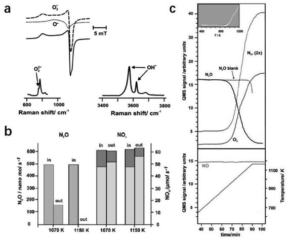
Ruszak et al. employed C12A7 as a catalyst for the N2O decomposition process.96 The trapped active oxygen species in C12A7 were identified by electron paramagnetic resonance (EPR) and Raman spectra (Fig. 21a). It is proposed that the transfer of oxygen species from the cage sites to the surface at high temperatures plays a key role in the decomposition of N2O. The abundant surface active oxygen promoted the abstract of oxygen from N2O. The conversion of the decomposed nitrous oxide reached ca. 90% upon 1150 K (Fig. 21b and c).
2.2.3.2 NOx reduction. The selective catalytic reductions (SCRs) of NOx by ammonia (4NO + 4NH3 + O2 → 4N2 + 6H2O) or hydrocarbons (NO + hydrocarbons → N2 + CO2 + H2O) are well-known approaches for reducing the emission of vehicle exhaust.97 However, the SCR route requires accurate control of the stoichiometric of ammonia and hydrocarbons. For the NOx storage/reduction (NSR) route, NOx can be stored in the catalyst during the oxygen lean period. Moreover, under oxygen-rich conditions, the encaged NOx is decomposed and subsequently reduced to nitrogen.98 To date, Ba-based catalysts are the most effective for NSR. However, it is easy to react with the sulfur impurity in real exhaust gases, which forms stable sulfates and inhibits the reaction, leading to the deactivation of the catalysts.99 Based on the storage and emission capacities of the active O− species of C12A7, Gao et al. developed a new NSR catalyst of K-doped C12A7:O−, in which the engaged O− can react with adsorbed NO and transform to NO3− and/or NO2−, avoiding the formation of stable sulfates.100 The NOx conversion of K-doped C12A7:O− can reach nearly 80% with the selectivity of N2 approaching 100%.
2.3. H− substitution
Hydrogen can operate as both an electron donor and acceptor owing to its medium electronegativity, and the charge states of hydrogen can be divided into H+ (proton), H0 (atomic hydrogen), and H− (hydride ion). The properties of hydrogen with different charge states quite differ from each other. Compared with H+ and H0, H− ions have rarely been investigated because of the instability of hydride ions. Interestingly, the positively charged sub-nano-cages of C12A7 provide a unique structure for stabilizing H− ions and forming C12A7:H−.The direct synthesis of C12A7:H− is achieved by a solid–state reaction under high pressure.102 The reducing atmosphere is important for preventing the unintended incorporation of impurity ions, such as O2− and OH− ions. The high-pressure apparatus can provide a sealed environment for the reaction of the starting materials under reductive conditions. The C12A7:H− with a high H− concentration of ∼0.6 × 1021 cm−3 was obtained by the reaction of CaO, Al2O3, and CaH2 with molar ratios of 11![[thin space (1/6-em)]](https://www.rsc.org/images/entities/char_2009.gif) :
:![[thin space (1/6-em)]](https://www.rsc.org/images/entities/char_2009.gif) 7
7![[thin space (1/6-em)]](https://www.rsc.org/images/entities/char_2009.gif) :
:![[thin space (1/6-em)]](https://www.rsc.org/images/entities/char_2009.gif) 1. The reaction condition required a high pressure ranging from 0.5 to 0.75 GPa as well as a high temperature ranging from 1200 to 1300 °C. Excess CaH2 is required as the H source for the incorporated H− ions during the treatment of high pressure.
1. The reaction condition required a high pressure ranging from 0.5 to 0.75 GPa as well as a high temperature ranging from 1200 to 1300 °C. Excess CaH2 is required as the H source for the incorporated H− ions during the treatment of high pressure.
A possible mechanism for the photo-induced conversion of C12A7:H− from an insulator to a conductor is proposed: UV irradiation induces an electron emission from the encaged H− ions (H− → H0 + e−). After that, Matsuishi et al. succeeded in observing the EPR signal of H0 in C12A7 after UV illumination at 4 K (Fig. 22b).35 The concentration of generated H0 is almost equal to that of F+ (Fig. 22c), which demonstrates that H− is trapped in the cage of C12A7 and follows photo-dissociation to H0 and F+. Fig. 22d shows that the fractions of H0 and F+ remain unchanged after thermal treatment. Almost no H0 was left after the treatment above ∼200 K, while ∼60% of the F+ remains even at 300 K, implying that partial H0 recombines with F+ to form H− (H0 + e− → H−), and the others have been removed differently without the consumption of the F+. A plausible reaction of H0 with free oxygen to form OH−, yielding additional F+: H0 + O2− → OH− + e− (or H0 + H0 → H2), also contributes to the retention of F+.
A similar mechanism was also proposed for MgO surfaces.106 Nearly 70% of H0 recombines with electrons, and the remaining H0 reacts with free oxygen to form OH−. The fraction of remaining F+ is experimentally estimated to be ∼60%. OH− is quite stable in the cage of C12A7 and does not react with trapped electrons at room temperature. When C12A7:H− is illuminated by UV light, several tens of percent of photoinduced electrons survive and yield hopping conductivity. At temperatures above ∼600 K, the OH− is reduced by trapped electrons to form H− and O2−, and therefore the conductivity is eliminated. The reactions proceed under UV illumination, as illustrated in Fig. 22e.
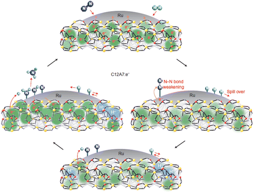 | ||
| Fig. 23 Possible pathway for the ammonia synthesis reaction over Ru/C12A7:e−. Copyright 2012, Springer Nature. | ||
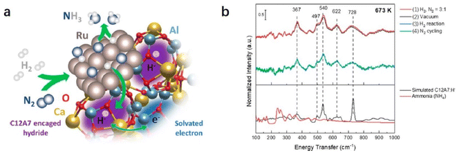
Recently, Kammert and co-workers reported that hydrogen is likely to be adsorbed on the catalyst surface rather than the storage of H− ion in the cage of C12A7:e−, which plays a dominant role in NH3 synthesis over Ru/C12A7:e− catalyst (Fig. 24a).107 They provided evidence for the presence of H− ions in the framework of Ru/C12A7:e− during NH3 synthesis by in situ inelastic neutron-scattering spectroscopy (Fig. 24b). It is founded that the encaged H− species are stable in the cage of C12A7:e−, which are not involved in the formation of NH3. Instead, dissociated hydrogen species on the Ru surface predominantly participate in ammonia synthesis. The extremely high coverage of nitrogen species on the surface of Ru/C12A7:e− is responsible for the anti-hydrogen poisoning over Ru. The RDS also shifted from N2 cleavage to the formation of the N–H bond, which agrees with Kitano's study.
2.4. Metal single atom fixation
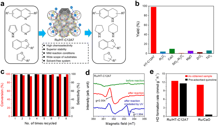
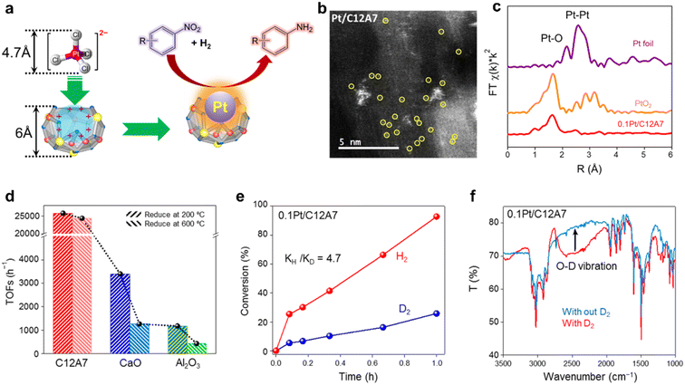
In recent years, single metal atom catalysts have been observed as rising stars for the green synthesis of fine chemicals owing to the ideal atomic utilization (100%).111–114 Moreover, the electronic structure of isolated metal atoms can be easily modified using support materials. Unfortunately, a highly dispersed single atom catalyst is difficult to prepare because of the metal atoms with extremely high surface energy, which are easy to aggregate and sinter.115 Defects are reported to be effective in stabilizing metal atoms; thus, different supports with rich surface defects are designed to prepare single atom catalysts.116 Considering the unique electronic and geometric structure of C12A7, the positively charged nanocages provide the possibility of anchoring single metal atoms.In the hydrogenation reaction of 4-chloronitrobenzene, the turnover frequencies (TOFs) of Pt/C12A7 reach as high as 25![[thin space (1/6-em)]](https://www.rsc.org/images/entities/char_2009.gif) 772 h−1, which is one order of magnitude higher than those of Pt/CaO (3396 h−1) and Pt/Al2O3 (1178 h−1) under the same reaction conditions (Fig. 26d). The reaction mechanism of Pt/C12A7 can be revealed by the combination of kinetic isotope effect (KIE) and Fourier transform infrared (FTIR) spectroscopy. The large primary isotope ratio (kH/kD) of 4.7 indicates that the rate determining step (RDS) may involve the dissociation of O–H bonds instead of Pt–H bond cleavage over Pt/C12A7 (Fig. 26e). This is further confirmed by the FTIR results, in which the stretching vibration of O–D is only detected on Pt/C12A7 (Fig. 26f). Thus, such heterolytic cleavage of H2 tend to generate Hδ+ and Hδ− at the Pt–O interface of Pt/C12A7, which is favored for the selective hydrogenation of nitro groups.
772 h−1, which is one order of magnitude higher than those of Pt/CaO (3396 h−1) and Pt/Al2O3 (1178 h−1) under the same reaction conditions (Fig. 26d). The reaction mechanism of Pt/C12A7 can be revealed by the combination of kinetic isotope effect (KIE) and Fourier transform infrared (FTIR) spectroscopy. The large primary isotope ratio (kH/kD) of 4.7 indicates that the rate determining step (RDS) may involve the dissociation of O–H bonds instead of Pt–H bond cleavage over Pt/C12A7 (Fig. 26e). This is further confirmed by the FTIR results, in which the stretching vibration of O–D is only detected on Pt/C12A7 (Fig. 26f). Thus, such heterolytic cleavage of H2 tend to generate Hδ+ and Hδ− at the Pt–O interface of Pt/C12A7, which is favored for the selective hydrogenation of nitro groups.
2.5. Other anion incorporation
In 2014, Hayashi and co-workers developed an ammonothermal method to encapsulate NH2− in C12A7 under the conditions of 35–55 MPa and 400–600 °C.15 The concentration of the encapsulated NH2− species is as high as 2.7 × 1020 cm−3, and the obtained C12A7:NH2− is chemically stable under ambient conditions. Such a large amount of encapsulated NH2− with high stability makes C12A7:NH2− a potential N1 source reagent for amination and amidation reactions. After that, Nakao et al. proposed a two-step mechanism of N2 incorporation into the cages of C12A7 by modeling density functional theory (DFT).118 It is reported that the decomposed NH2− species from NH3 is first incorporated into the surface cage structure of C12A7:e−. Then, the as-captured NH2− species react with each other to form N2. Attention should be paid because such an encapsulation strategy of electroneutral N2 molecules differs from the negatively charged species previously reported in C12A7.
Because of its strong etching ability, F− ion is widely used in the fields of semiconductor etching, surface modifications, and so on.123,124 The development of a suitable carrier, which can store F− species stably and emit continuously, is highly demanded to promote the employment of F− ion. In this context, Song et al. reported the preparation of the F− storage emission material of C12A7–F− through a solid-state reaction.18 The concentration of the incorporated F− of C12A7–F− can reach ∼1.9 × 1021 cm−3, and the emission current density of F− was as high as 16.7 ± 0.8 μA cm−2 at 800 °C under an extraction field of 1200 V cm−1.
3. Conclusion and perspectives
In this review, we summarized recent progress in the design and preparation of active anion-bearing C12A7 materials as catalysts and reagents in the fields of heterogeneous catalysis and important organic synthetic reactions. Owing to the versatility of C12A7 materials with various anion substitutions as well as their unique features (low work function/electron donation, metal–insulator transformation, and sub-nanometer-sized cage confinement), a series of C12A7-based functional materials have been designed and fabricated to satisfy specific catalytic and synthetic chemical processes. Important research contributions are highlighted to illustrate the manipulation of active anions (e.g., e−, O−, O2−, H− and metal single atom species) with enhanced performance owing to their potential chemical applications.Although significant progress has been made, great challenges remain in the preparation and application of C12A7-based materials. (1) Owing to the necessity of employing harsh conditions to achieve active anion-bearing C12A7, the surface areas of these materials are limited to a few m2 g−1, which prevents further improvement of their catalytic performance. (2) It is always a conundrum to identify the interaction between the substituted active anions (especially the anions, such as O−, O2−, H−, NH2− and OH−) and loaded active metals, which restricts the purposed design and control synthesis of C12A7-based materials with desired active sites. (3) Although high performance has been achieved for C12A7-based materials, the exact reaction mechanism needs to be studied in depth to improve their functionality.
In a further study, the innovation of synthetic strategies and the fabrication of C12A7 with porous structure open new room for C12A7-based materials in chemical reactions. In addition, the employment of in situ characterization and tracer techniques would also be of great help in understanding both the active center structure and reaction mechanism to achieve a more rational material design. With rapid advances in synthetic and characteristic strategies of nanoscience and nanotechnology, the design and controlled synthesis of active anion-bearing C12A7 functional materials greatly contributes to sustainable development in the field of catalysis and organic synthesis.
Conflicts of interest
There are no conflicts to declare.References
- A. G. Slater and A. I. Cooper, Science, 2015, 348, aaa8075 CrossRef PubMed.
- X. Fan and Y. Jiao, in Sustainable Nanoscale Engineering, 2020, pp. 115–137 Search PubMed.
- R.-B. Lin, S. Xiang, W. Zhou and B. Chen, Chem, 2020, 6, 337–363 CAS.
- F. J. Maksoud, M. F. Velazquez de la Paz, A. J. Hann, J. Thanarak, G. C. Reilly, F. Claeyssens, N. H. Green and Y. S. Zhang, J. Mater. Chem. B, 2022, 10, 8111–8165 RSC.
- J. Prech, P. Pizarro, D. P. Serrano and J. Cejka, Chem. Soc. Rev., 2018, 47, 8263–8306 RSC.
- G. Cai, P. Yan, L. Zhang, H. C. Zhou and H. L. Jiang, Chem. Rev., 2021, 121, 12278–12326 CrossRef CAS PubMed.
- W. Tian, H. Zhang, X. Duan, H. Sun, G. Shao and S. Wang, Adv. Funct. Mater., 2020, 30, 1909265 CrossRef CAS.
- Q. Zhang, S. Gao and J. Yu, Chem. Rev., 2022, 123, 6039–6106 CrossRef PubMed.
- J. Jeevaratnam, L. S. D. Glasser and F. P. Glasser, Nature, 1962, 194, 764–765 CrossRef CAS.
- S. Matsuishi, Y. Toda, M. Miyakawa, K. Hayashi, T. Kamiya, M. Hirano, I. Tanaka and H. Hosono, Science, 2003, 301, 626–629 CrossRef CAS PubMed.
- K. Hayashi, S. Matsuishi, N. Ueda, M. Hirano and H. Hosono, Chem. Mater., 2003, 15, 1851–1854 CrossRef CAS.
- K. Hayashi, M. Hirano, S. Matsuishi and H. Hosono, J. Am. Chem. Soc., 2002, 124, 738–739 CrossRef CAS PubMed.
- K. Hayashi, J. Solid State Chem., 2011, 184, 1428–1432 CrossRef CAS.
- J. Li, F. Huang, L. Wang, S. Q. Yu, Y. Torimoto, M. Sadakata and Q. X. Li, Chem. Mater., 2005, 17, 2771–2774 CrossRef CAS.
- F. Hayashi, Y. Tomota, M. Kitano, Y. Toda, T. Yokoyama and H. Hosono, J. Am. Chem. Soc., 2014, 136, 11698–11706 CrossRef CAS PubMed.
- G. I. Zhmoidin and A. K. Chatterjee, Cem. Concr. Res., 1984, 14, 386–396 CrossRef CAS.
- M. Miyakawa, H. Kamioka, M. Hirano, T. Kamiya, P. V. Sushko, A. L. Shluger, N. Matsunami and H. Hosono, Phys. Rev. B: Condens. Matter Mater. Phys., 2006, 73, 205108 CrossRef.
- C. Song, J. Sun, J. Li, S. Ning, M. Yamamoto, J. Tu, Y. Torimoto and Q. Li, J. Phys. Chem. C, 2008, 112, 19061–19068 CrossRef CAS.
- J. Sun, C. Song, S. Ning, S. Lin and Q. Li, Chin. J. Chem. Phys., 2009, 22, 417–422 CrossRef CAS.
- A. Schmidt, M. Lerch, J.-P. Eufinger, J. Janek, R. Dolle, H.-D. Wiemh€ ofer, I. Tranca, M. M. Islam, T. Bredow, H. Boysen and M. Hoelzel, Solid State Sci., 2014, 38, 69–78 CrossRef CAS.
- M. Lacerda, J. T. S. Irvine, F. P. Glasser and A. R. West, Nature, 1988, 332, 525–526 CrossRef CAS.
- H. Hosono, K. Hayashi, K. Kajihara, P. V. Sushko and A. L. Shluger, Solid State Ionics, 2009, 180, 550–555 CrossRef CAS.
- A. Schmidt, M. Lerch, J. P. Eufinger, J. Janek, I. Trance, M. M. Islam, T. Bredow, R. Dolle, H. D. Wiemhöfer, H. Boysen and M. Hölzel, Solid State Ionics, 2014, 254, 48–58 CrossRef CAS.
- J.-P. Eufinger, A. Schmidt, M. Lerch and J. Janek, Phys. Chem. Chem. Phys., 2015, 17, 6844–6857 RSC.
- S. W. Kim, S. Matsuishi, T. Nomura, Y. Kubota, M. Takata, K. Hayashi, T. Kamiya, M. Hirano and H. Hosono, Nano Lett., 2007, 7, 1138–1143 CrossRef CAS PubMed.
- M. Miyakawa, S. W. Kim, M. Hirano, Y. Kohama, H. Kawaji, T. Atake, H. Ikegami, K. Kono and H. Hosono, J. Am. Chem. Soc., 2007, 129, 7270–7271 CrossRef CAS PubMed.
- Y. Kohama, S. W. Kim, T. Tojo, H. Kawaji, T. Atake, S. Matsuishi and H. Hosono, Phys. Rev. B: Condens. Matter Mater. Phys., 2008, 77, 092505 CrossRef.
- S. W. Kim, M. Miyakawa, M. Hirano, Y. Kohama, H. Kawaji, T. Atake, H. Ikegami, K. Kono and H. Hosono, Mater. Trans., 2008, 49, 1748–1752 CrossRef CAS.
- S. Tanaka, T. Kato, A. Miyake, T. Kagayama, K. Shimizu, S. W. Kim, S. Matsuishi and H. Hosono, J. Korean Phys. Soc., 2013, 63, 477–480 CrossRef CAS.
- Y. Toda, S. W. Kim, K. Hayashi, M. Hirano, T. Kamiya, H. Hosono, T. Haraguchi and H. Yasuda, Appl. Phys. Lett., 2005, 87, 254103 CrossRef.
- T. Kamiya, S. Aiba, M. Miyakawa, K. Nomura, S. Matsuishi, K. Hayashi, K. Ueda, M. Hirano and H. Hosono, Chem. Mater., 2005, 17, 6311–6316 CrossRef CAS.
- S. W. Kim, Y. Toda, K. Hayashi, M. Hirano and H. Hosono, Chem. Mater., 2006, 18, 1938–1944 CrossRef CAS.
- Y. Toda, S. Matsuishi, K. Hayashi, K. Ueda, T. Kamiya, M. Hirano and H. Hosono, Adv. Mater., 2004, 16, 685–689 CrossRef CAS.
- Q. X. Li, K. Hayashi, M. Nishioka, H. Kashiwagi, M. Hirano, Y. Torimoto, H. Hosono and M. Sadakata, Appl. Phys. Lett., 2002, 80, 4259–4261 CrossRef CAS.
- S. Matsuishi, K. Hayashi, M. Hirano and H. Hosono, J. Am. Chem. Soc., 2005, 127, 12454–12455 CrossRef CAS PubMed.
- T. N. Ye, Z. Xiao, J. Li, Y. Gong, H. Abe, Y. Niwa, M. Sasase, M. Kitano and H. Hosono, Nat. Commun., 2020, 11, 1020 CrossRef CAS PubMed.
- Y. Toda, H. Yanagi, E. Ikenaga, J. J. Kim, M. Kobata, S. Ueda, T. Kamiya, M. Hirano, K. Kobayashi and H. Hosono, Adv. Mater., 2007, 19, 3564–3569 CrossRef CAS.
- K. Hayashi, S. Matsuishi, T. Kamiya, M. Hirano and H. Hosono, Nature, 2002, 419, 462–465 CrossRef CAS PubMed.
- M. Miyakawa, Y. Toda, K. Hayashi, M. Hirano, T. Kamiya, N. Matsunami and H. Hosono, J. Appl. Phys., 2005, 97, 023510 CrossRef.
- S.-W. Kim, K. Hayashi, M. Hirano, H. Hosono and I. Tanaka, J. Am. Ceram. Soc., 2006, 89, 3294–3298 CrossRef CAS.
- S. Kim, M. Miyakawa, K. Hayashi, T. Sakai, M. Hirano and H. Hosono, J. Am. Chem. Soc., 2005, 127, 1370–1371 CrossRef CAS PubMed.
- S. Matsuishi, T. Nomura, M. Hirano, K. Kodama, S.-i. Shamoto and H. Hosono, Chem. Mater., 2009, 21, 2589–2591 CrossRef CAS.
- D. Jiang, Z. Zhao, S. Mu, H. Qian and J. Tong, Inorg. Chem., 2019, 58, 960–967 CrossRef CAS PubMed.
- F. Li, X. Zhang and J. Zhang, Ceram. Int., 2019, 45, 23830–23835 CrossRef.
- Y. Xiao, X. Zhang and R. Li, J. Am. Ceram. Soc., 2020, 104, 1641–1648 CrossRef.
- K. Kurashige, Y. Toda, S. Matstuishi, K. Hayashi, M. Hirano and H. Hosono, Cryst. Growth Des., 2006, 6, 1602–1605 CrossRef CAS.
- S. Gambarotta and J. Scott, Angew. Chem., Int. Ed., 2004, 43, 5298–5308 CrossRef CAS PubMed.
- S. Souma, T. Arakane, T. Sato, T. Takahashi, S. Wng Kim, S. Matsuishi and H. Hosono, J. Phys. Soc. Jpn., 2010, 79, 103704 CrossRef.
- M. Kitano, Y. Inoue, Y. Yamazaki, F. Hayashi, S. Kanbara, S. Matsuishi, T. Yokoyama, S. W. Kim, M. Hara and H. Hosono, Nat. Chem., 2012, 4, 934–940 CrossRef CAS PubMed.
- S. Kanbara, M. Kitano, Y. Inoue, T. Yokoyama, M. Hara and H. Hosono, J. Am. Chem. Soc., 2015, 137, 14517–14524 CrossRef CAS PubMed.
- H. Hosono, Catal. Lett., 2022, 152, 307–314 CrossRef CAS.
- M. Kitano, S. Kanbara, Y. Inoue, N. Kuganathan, P. V. Sushko, T. Yokoyama, M. Hara and H. Hosono, Nat. Commun., 2015, 6, 6731 CrossRef CAS PubMed.
- Y. Inoue, M. Kitano, M. Tokunari, T. Taniguchi, K. Ooya, H. Abe, Y. Niwa, M. Sasase, M. Hara and H. Hosono, ACS Catal., 2019, 9, 1670–1679 CrossRef CAS.
- C. J. H. Jacobsen, S. Dahl, B. S. Clausen, S. Bahn, A. Logadottir and J. K. Nørskov, J. Am. Chem. Soc., 2001, 123, 8404–8405 CrossRef CAS PubMed.
- F. Hayashi, Y. Toda, Y. Kanie, M. Kitano, Y. Inoue, T. Yokoyama, M. Hara and H. Hosono, Chem. Sci., 2013, 4, 3124–3130 RSC.
- P. Claus, A. Brückner, C. Mohr and H. Hofmeister, J. Am. Chem. Soc., 2000, 122, 11430–11439 CrossRef CAS.
- T. N. Ye, J. Li, M. Kitano, M. Sasase and H. Hosono, Chem. Sci., 2016, 7, 5969–5975 RSC.
- H. Abe, Y. Niwa, M. Kitano, Y. Inoue, Y. Murakami, T. Yokoyama, M. Hara and H. Hosono, J. Phys. Chem. C, 2016, 120, 8711–8716 CrossRef CAS.
- M. J. Sharif, M. Kitano, Y. Inoue, Y. Niwa, H. Abe, T. Yokoyama, M. Hara and H. Hosono, J. Phys. Chem. C, 2015, 119, 11725–11731 CrossRef CAS.
- D. Widmann and R. J. Behm, Acc. Chem. Res., 2014, 47, 740–749 CrossRef CAS PubMed.
- B. Yoon, H. Hakkinen, U. Landman, A. S. Worz, J. M. Antonietti, S. Abbet, K. Judai and U. Heiz, Science, 2005, 307, 403–407 CrossRef CAS PubMed.
- H. Öström, H. Öberg, H. Xin, J. LaRue, M. Beye, M. Dell’Angela, J. Gladh, M. L. Ng, J. A. Sellberg, S. Kaya, G. Mercurio, D. Nordlund, M. Hantschmann, F. Hieke, D. Kühn, W. F. Schlotter, G. L. Dakovski, J. J. Turner, M. P. Minitti, A. Mitra, S. P. Moeller, A. Föhlisch, M. Wolf, W. Wurth, M. Persson, J. K. Nørskov, F. Abild-Pedersen, H. Ogasawara, L. G. M. Pettersson and A. Nilsson, Science, 2015, 347, 978–982 CrossRef PubMed.
- G. C. Fu, Acc. Chem. Res., 2008, 41, 1555–1564 CrossRef CAS PubMed.
- B. Dai, Z. Li, M. Xu, J. Li, Y. Lu, J. Zai, L. Fan, S.-W. Park, M. Sasase, M. Kitano and H. Hosono, J. Mater. Chem. A, 2023 10.1039/d2ta08899a.
- J. Li, B. Yin, T. Fuchigami, S. Inagi, H. Hosono and S. Ito, Electrochem. Commun., 2012, 17, 52–55 CrossRef CAS.
- J. Li, S. Inagi, T. Fuchigami, H. Hosono and S. Ito, Electrochem. Commun., 2014, 44, 45–48 CrossRef CAS.
- K. Khan, A. Khan Tareen, J. Li, U. Khan, A. Nairan, Y. Yuan, X. Zhang, M. Yang and Z. Ouyang, Dalton Trans., 2018, 47, 13498–13506 RSC.
- Q. Hu, R. Tan, J. Li and W. Song, J. Phys. Chem. Solids, 2021, 149, 109810 CrossRef CAS.
- H. Buchammagari, Y. Toda, M. Hirano, H. Hosono, D. Takeuchi and K. Osakada, Org. Lett., 2007, 9, 4287–4289 CrossRef CAS PubMed.
- S. M. Kim, H. S. Yoo, H. Hosono, J. W. Yang and S. W. Kim, Sci. Rep., 2015, 5, 10366 CrossRef PubMed.
- Y. Toda, H. Hirayama, N. Kuganathan, A. Torrisi, P. V. Sushko and H. Hosono, Nat. Commun., 2013, 4, 2378 CrossRef PubMed.
- J. H. Lunsford, Adv. Catal., 1972, 22, 265–344 CAS.
- M. Che and A. Tench, Adv. Catal., 1983, 32, 1–148 CAS.
- H. Hosono and Y. Abe, Inorg. Chem., 1987, 26, 1192–1195 CrossRef CAS.
- S. Yang, J. N. Kondo, K. Hayashi, M. Hirano, K. Domen and H. Hosono, Chem. Mater., 2003, 16, 104–110 CrossRef.
- K. Hayashi, S. Matsuishi, M. Hirano and H. Hosono, J. Phys. Chem. B, 2004, 108, 8920–8925 CrossRef CAS.
- S. Matsuishi, K. Hayashi, M. Hirano, I. Tanaka and H. Hosono, J. Phys. Chem. B, 2004, 108, 18557–18568 CrossRef CAS.
- K. Hayashi, M. Hirano and H. Hosono, Chem. Lett., 2005, 34, 586–587 CrossRef CAS.
- A. T. Ashcroft, A. K. Cheetham, J. S. Foord, M. L. H. Green, C. P. Grey, A. J. Murrell and P. D. F. Vernon, Nature, 1990, 344, 319–321 CrossRef CAS.
- P. D. F. Vernon, M. L. H. Green, A. K. Cheetham and A. T. Ashcroft, Catal. Lett., 1990, 6, 181–186 CrossRef CAS.
- P. D. F. Vernon, M. L. H. Green, A. K. Cheetham and A. T. Ashcroft, Catal. Today, 1992, 13, 417–426 CrossRef CAS.
- L. Pino, A. Vita, M. Cordaro, V. Recupero and M. S. Hegde, Appl. Catal., A, 2003, 243, 135–146 CrossRef CAS.
- S. Yang, J. N. Kondo, K. Hayashi, M. Hirano, K. Domen and H. Hosono, Appl. Catal., A, 2004, 277, 239–246 CrossRef CAS.
- M. Steinberg, Int. J. Hydrogen Energy, 1989, 14, 797–820 CrossRef CAS.
- B. McLellan, E. Shoko, A. Dicks and J. Dinizdacosta, Int. J. Hydrogen Energy, 2005, 30, 669–679 CrossRef CAS.
- H. Pedersenmjaanes, L. Chan and E. Mastorakos, Int. J. Hydrogen Energy, 2005, 30, 579–592 CrossRef CAS.
- D. Wang, S. Czernik and E. Chornet, Energy Fuels, 1998, 12, 19–24 CrossRef CAS.
- L. a. Garcia, R. French, S. Czernik and E. Chornet, Appl. Catal., A, 2000, 201, 225–239 CrossRef CAS.
- X. Zhu and R. Venderbosch, Fuel, 2005, 84, 1007–1010 CrossRef CAS.
- Z. Wang, Y. Pan, T. Dong, X. Zhu, T. Kan, L. Yuan, Y. Torimoto, M. Sadakata and Q. Li, Appl. Catal., A, 2007, 320, 24–34 CrossRef CAS.
- R. J. Schmidt, Appl. Catal., A, 2005, 280, 89–103 CrossRef CAS.
- A. Reitzmann, E. Klemm and G. Emig, Chem. Eng. J., 2002, 90, 149–164 CrossRef CAS.
- T. Dong, J. Li, F. Huang, L. Wang, J. Tu, Y. Torimoto, M. Sadakata and Q. Li, Chem. Commun., 2005, 2724–2726 RSC.
- J. Pérez-Ramırez, F. Kapteijn, K. Schöffel and J. A. Moulijn, Appl. Catal., B, 2003, 44, 117–151 CrossRef.
- P. Pietrzyk, F. Zasada, W. Piskorz, A. Kotarba and Z. Sojka, Catal. Today, 2007, 119, 219–227 CrossRef CAS.
- M. Ruszak, M. Inger, S. Witkowski, M. Wilk, A. Kotarba and Z. Sojka, Catal. Lett., 2008, 126, 72–77 CrossRef CAS.
- F. Witzel, G. A. Sill and W. K. Hall, J. Catal., 1994, 149, 229–237 CrossRef CAS.
- E. Fridell, H. Persson, L. Olsson, B. Westerberg, A. Amberntsson and M. Skoglundh, Top. Catal., 2001, 16, 133–137 CrossRef.
- A. Amberntsson, M. Skoglundh, M. Jonsson and E. Fridell, Catal. Today, 2002, 73, 279–286 CrossRef CAS.
- A. Gao, X. Zhu, H. Wang, J. Tu, P. Lin, Y. Torimoto, M. Sadakata and Q. Li, J. Phys. Chem. B, 2006, 110, 11854–11862 CrossRef CAS PubMed.
- K. Hayashi, P. V. Sushko, Y. Hashimoto, A. L. Shluger and H. Hosono, Nat. Commun., 2014, 5, 3515 CrossRef PubMed.
- M. Miyakawa, H. Murata and M. Imai, Ceram. Int., 2019, 45, 16028–16031 CrossRef CAS.
- C. J. Delbecq, B. Smaller and P. H. Yuster, Phys. Rev., 1956, 104, 599–604 CrossRef CAS.
- C. J. Delbecq and P. H. Yuster, Phys. Rev., 1956, 104, 605–606 CrossRef CAS.
- M. Chiesa, M. C. Paganini, E. Giamello, D. M. Murphy, C. Di Valentin and G. Pacchioni, Acc. Chem. Res., 2006, 39, 861–867 CrossRef CAS PubMed.
- D. Ricci, C. Di Valentin, G. Pacchioni, P. V. Sushko, A. L. Shluger and E. Giamello, J. Am. Chem. Soc., 2003, 125, 738–747 CrossRef CAS PubMed.
- J. Kammert, J. Moon, Y. Cheng, L. Deamen, S. Irle, V. Fung, J. Liu, K. Page, X. Ma, V. Phaneuf, J. Tong, A. J. Ramirez-Cuesta and Z. Wu, J. Am. Chem. Soc., 2020, 142, 7655–7667 CrossRef CAS PubMed.
- V. Sridharan, P. A. Suryavanshi and J. C. Menendez, Chem. Rev., 2011, 111, 7157–7259 CrossRef CAS PubMed.
- D. R. Aireddy and K. Ding, ACS Catal., 2022, 12, 4707–4723 CrossRef CAS.
- T.-N. Ye, J. Li, M. Kitano and H. Hosono, Green Chem., 2017, 19, 749–756 RSC.
- B. Qiao, A. Wang, X. Yang, L. F. Allard, Z. Jiang, Y. Cui, J. Liu, J. Li and T. Zhang, Nat. Chem., 2011, 3, 634–641 CrossRef CAS PubMed.
- P. Liu, Y. Zhao, R. Qin, S. Mo, G. Chen, L. Gu, D. M. Chevrier, P. Zhang, Q. Guo, D. Zhang, B. Wu, G. Fu and N. Zheng, Science, 2016, 352, 797–801 CrossRef CAS PubMed.
- N. Cheng, S. Stambula, D. Wang, M. N. Banis, J. Liu, A. Riese, B. Xiao, T.-K. Sham, L.-M. Liu, G. A. Botton and X. Sun, Nat. Commun., 2016, 7, 13638 CrossRef CAS PubMed.
- A. Wang, J. Li and T. Zhang, Nat. Rev. Chem., 2018, 2, 65–81 CrossRef CAS.
- X. F. Yang, A. Wang, B. Qiao, J. Li, J. Liu and T. Zhang, Acc. Chem. Res., 2013, 46, 1740–1748 CrossRef CAS PubMed.
- L. Nie, D. Mei, H. Xiong, B. Peng, Z. Ren, X. I. P. Hernandez, A. DeLaRiva, M. Wang, M. H. Engelhard, L. Kovarik, A. K. Datye and Y. Wang, Science, 2017, 358, 1419–1423 CrossRef CAS PubMed.
- P. Chen, Z. Xiong, J. Luo, J. Lin and K. L. Tan, Nature, 2002, 420, 302–304 CrossRef CAS PubMed.
- T. Nakao, K. Ogasawara, M. Kitano, S. Matsuishi, P. V. Sushko and H. Hosono, J. Phys. Chem. Lett., 2021, 12, 1295–1299 CrossRef CAS PubMed.
- M. V. Twigg and M. S. Spencer, Appl. Catal., A, 2001, 212, 161–174 CrossRef CAS.
- M. Kurtz, H. Wilmer, T. Genger, O. Hinrichsen and M. Muhler, Catal. Lett., 2003, 86, 77–80 CrossRef CAS.
- S. Murata and K.-I. Aika, Appl. Catal., A, 1992, 82, 1–12 CrossRef CAS.
- J. Li, M. Kitano, T.-N. Ye, M. Sasase, T. Yokoyama and H. Hosono, ChemCatChem, 2017, 9, 3078–3083 CrossRef CAS.
- T. Shibayama, H. Shindo and Y. Horiike, Plasma Sources Sci. Technol., 1996, 5, 254–259 CrossRef CAS.
- C. M. S. Rauthan, G. S. Virdi, B. C. Pathak and A. Karthigeyan, J. Appl. Phys., 1998, 83, 3668–3677 CrossRef CAS.
- A. Schmidt, H. Boysen, A. Senyshyn and M. Lerch, Z. Kristallogr. Cryst. Mater., 2014, 229, 427–434 CrossRef CAS.
- B. Henderson and W. A. Sibley, J. Chem. Phys., 1971, 55, 1276–1285 CrossRef CAS.
- B. Henderson, J. L. Kolopus and W. P. Unruh, J. Chem. Phys., 1971, 55, 3519–3524 CrossRef CAS.
- H. Engstrom, J. B. Bates, J. C. Wang and M. M. Abraham, Phys. Rev. B: Condens. Matter Mater. Phys., 1980, 21, 1520–1526 CrossRef CAS.
- R. Ramírez, I. Colera, R. González, Y. Chen and M. R. Kokta, Phys. Rev. B: Condens. Matter Mater. Phys., 2004, 69, 014302 CrossRef.
- E. Giamello, M. C. Paganini, D. M. Murphy, A. M. Ferrari and G. Pacchioni, J. Phys. Chem. B, 1997, 101, 971–982 CrossRef CAS.
- V. K. Singh and F. P. Glasser, Ceram. Int., 1988, 14, 59–62 CrossRef CAS.
Footnote |
| † Xiangyu Zhang, Zichuang Li and Miao Xu contributed equally to this work. |
| This journal is © The Royal Society of Chemistry 2023 |


