Diketopyrrolopyrrole-based conjugated polymers containing planar benzo[c]cinnoline and tetraazapyrene structures for high-performance and long-term stable triboelectric nanogenerators†
Kuang-Hao
Cheng
 a,
Cheng-You
Tsai
a,
Yu-Han
Wang
a,
Cheng-You
Tsai
a,
Yu-Han
Wang
 a,
Shyam S.
Pandey
 b,
Chih-Yu
Chang
 *a and
Jyh-Chien
Chen
 *a
*a
aDepartment of Materials Science and Engineering, National Taiwan University of Science and Technology, Taipei, 10607, Taiwan. E-mail: cychang@gapps.ntust.edu.tw; jcchen@mail.ntust.edu.tw
bGraduate School of Life Science and Systems Engineering, Kyushu Institute of Technology, 2-4 Hibikino, Wakamatsu, Kitakyushu 808-0196, Japan
First published on 3rd November 2022
Abstract
In this work, diketopyrrolopyrrole (DPP)-based conjugated polymers, benzo[c]cinnoline/diketopyrrolopyrrole (BZC–DPP) and tetraazapyrene/diketopyrrolopyrrole (TAP–DPP), are incorporated as the surface modification layer for a triboelectric nanogenerator (TENG). Both polymers exhibit high planarity and extended π-electron delocalization, which can facilitate the electron transfer between the triboelectric layers. Compared with BZC–DPP, TAP–DPP possesses stronger electron-withdrawing ability, which would be beneficial for the generation of triboelectric charges. Consequently, the TENG based on TAP–DPP delivers an open circuit voltage (Voc) of 328 V, a short circuit current (Isc) of 27 μA, and an instantaneous power density of 2.4 W m−2. Additionally, the resulting TENG retains an almost comparable Voc even after continuous operation up to 200![[thin space (1/6-em)]](https://www.rsc.org/images/entities/char_2009.gif) 000 cycles. To the best of our knowledge, this is the first successful demonstration of using DPP-based conjugated polymers as the surface modification layer for high-performance and long-term stable TENGs. This work can not only open a new avenue for efficient and stable TENGs using DPP-based conjugated polymers as the surface modification layer, but also stimulate further research efforts towards the development of new conjugated polymers for versatile applications of TENGs.
000 cycles. To the best of our knowledge, this is the first successful demonstration of using DPP-based conjugated polymers as the surface modification layer for high-performance and long-term stable TENGs. This work can not only open a new avenue for efficient and stable TENGs using DPP-based conjugated polymers as the surface modification layer, but also stimulate further research efforts towards the development of new conjugated polymers for versatile applications of TENGs.
Introduction
Triboelectric nanogenerators (TENGs) that can harvest energy from ambient sources and convert it into electricity have drawn much attention recently due to their potential to act as a viable candidate for powering wearable and portable electronic devices.1–3 Typically, the output performance of TENGs mainly depends on the triboelectric surface charge density.4,5 To maximize the triboelectric surface charge density, rational selection of the appropriate triboelectric materials becomes essential. Typically, the triboelectric surface charge density is primarily determined by different electron affinities of two triboelectric layers. Among various strategies, surface modification via chemical functionalization has been proven to be a promising approach to enlarge the difference in electronegativity between the triboelectric layers.6,7 In particular, in contrast to inorganic materials, organic materials exert several unique advantages such as mechanical flexibility, low-temperature solution processability, and high structural tunability.8,9 Although significant progress has been made towards developing organic-based TENG devices, commonly used organic materials are insulating,10–15 which may impede the triboelectric charge generation between the triboelectric materials due to their wide bandgap.16,17 By contrast, the relatively narrow bandgaps of semiconducting π-conjugated polymers are expected to facilitate the charge transfer between the triboelectric materials.16,17 This strategy may open a new avenue for developing high-performance TENGs with diverse applications.18–20 Typically, manipulation of the functional groups of the polymers at the molecular level can significantly affect the output performance of TENGs.18,21 This consideration becomes of particular importance in conjugated polymers because molecular rigidity and planarity play an essential role in determining the electrical properties.22,23 Nevertheless, the realization of long-term stable TENGs has rarely been reported.18–20Semiconducting π-conjugated polymers with an alternating arrangement of donor and acceptor units are important materials for printed organic optoelectronic and electronic devices.24–28 In addition to their possible low-cost production, lightweight, flexible, and stretchable electronic devices are highly expected.29–31 In particular, the electronic properties of such polymers can be engineered easily through chemical modification.32–34 Furthermore, most conjugated polymers can be soluble in common solvents. The unique advantages of conjugated polymers open up a new avenue for diverse applications, including organic field-effect transistors (OFETs),35–38 organic photovoltaic cells (OSCs),39–41 and organic light-emitting diodes (OLEDs).42–46 These applications have come closer to commercial reality with the development of molecular designs, processing techniques, and device architectures. It is well known that the incorporation of strong electron-withdrawing ability units into the polymer backbone can effectively lower the highest occupied molecular orbital (HOMO) and the lowest unoccupied molecular orbital (LUMO) energy levels.47 In strong electron-withdrawing ability units, the aza structure is an effective functional group with strong electron-withdrawing ability like tetrazine and pyridazine.48–50 In our laboratory's previous research, we have published N-containing heterocyclic structures such as benzo[c]cinnoline (BZC) and tetraazapyrene (TAP) containing one and two aza structures for various applications.51–54 BZC and TAP are planar structures with strong electron-withdrawing ability. Some results reveal that both structures have great potential as an acceptor due to their low-lying energy levels.51,53,54 Conjugated polymers, BZCTVT and TAPTVT, containing thiophene-vinylene-thiophene (TVT) and BZC and TAP can be used as semiconducting layers for OFET applications.51
In this work, we demonstrate a high-performance and stable TENG by employing heterocyclic semiconducting π-conjugated polymers as the surface modification layer. The TENG device structure is depicted in Fig. 1. Two conjugated polymers, including benzo[c]cinnoline/diketopyrrolopyrrole (BZC–DPP) and tetraazapyrene/diketopyrrolopyrrole (TAP–DPP), are synthesized and characterized (see their chemical structures in Fig. 1). Generally, DPP-based conjugated polymers have manifested significant improvements in the optoelectronic properties of the electronic devices due to the favourable characteristics of the DPP unit, such as their narrow-bandgap nature and appropriate energy level tuning.25,55 Furthermore, DPP functional groups can increase the electron-withdrawing ability and lower the energy levels of these molecules,25,56–58 thereby improving the triboelectric charge transfer between the electrode and dielectric layer. The relationship between the molecular structures and the corresponding TENG output performance is systematically investigated. Our results indicate that BZC and TAP possess planar structures with strong electron-withdrawing ability, enabling them to exhibit desired energy level for acting as an effective surface modification layer. Importantly, the TENG device with a TAP–DPP modification layer exhibits superior output performance than BZC–DPP, delivering an open circuit voltage (Voc) of 328 V, short circuit current (Isc) of 27 μA, and power density of 2.4 W m−2. Furthermore, the resulting TENG retains almost an unchanged Voc even after continuous operation up to 200![[thin space (1/6-em)]](https://www.rsc.org/images/entities/char_2009.gif) 000 cycles. To the best of our knowledge, this is the first demonstration of using DPP-based conjugated polymers as the modification layer for achieving high-performance and long-term stable TENGs. This work exemplifies the importance of surface modification via DPP-based conjugated polymers for TENGs and can stimulate the development of new conjugated polymers for TENG applications.
000 cycles. To the best of our knowledge, this is the first demonstration of using DPP-based conjugated polymers as the modification layer for achieving high-performance and long-term stable TENGs. This work exemplifies the importance of surface modification via DPP-based conjugated polymers for TENGs and can stimulate the development of new conjugated polymers for TENG applications.
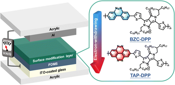 | ||
| Fig. 1 Schematic illustration of the device architecture used in this study and chemical structures of BZC–DPP and TAP–DPP. | ||
Experimental
Monomer synthesis
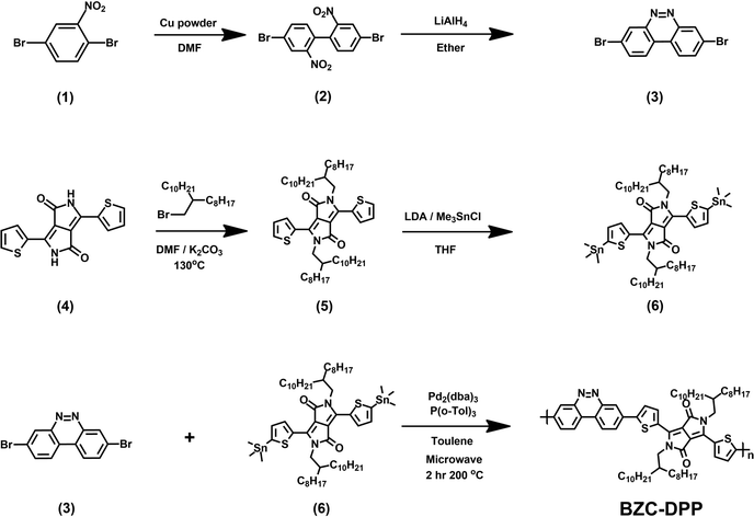
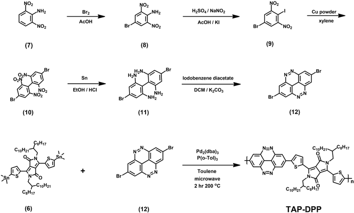
All the starting materials and reagents were purchased from Acros, Sigma-Aldrich, or other commercial sources and used directly without further purification unless specified otherwise. Anhydrous toluene was dried with calcium hydride and distilled prior to use. Schemes 1 and 2 illustrate the synthetic routes of dibromide monomers (3) and (12), containing BZC and TAP structures, respectively. Compound (3) and compound (12) were synthesized from 2,5-dibromonitrobenzene (1) and 2,6-dinitroaniline (7) reported in our previous publication.51 The synthesis of compound (6) (DPP) followed the procedures described in the literature.48The 1H NMR spectra of compounds (3), (6), and (12) are shown in Fig. S13–15 (ESI†).BZC–DPP synthesis
A 10 mL microwave vessel equipped with a stir bar was charged with compound (6) (0.558 g, 0.47 mmol), compound (3) (0.159 g, 0.47 mmol), Pd2(dba)3 (0.017 g, 0.019 mmol), and P(o-Tol)3 (0.017 g, 0.057 mmol) in the glovebox and was sealed with a Teflon cap. After anhydrous chlorobenzene (4.7 mL) was added by syringe, the vessel was placed into the microwave reactor and subjected to the following reaction conditions (Microwave Setups: Anton Paar Monowave 300 Microwave Synthesis Reactor; temperature = 200 °C; time = 120 minutes; pressure = 32 bar; Stirring = 800 rpm). After the reaction was completed, the reaction mixture was cooled to 55 °C and then dropped into methanol slowly. A small amount of chloroform was added to dissolve the residual product in the vessel. The residual was also precipitated in methanol. The precipitated polymer was collected into a thimble filter and washed by Soxhlet extraction using methanol, acetone, hexane, and chloroform, sequentially. The chloroform fraction was concentrated and precipitated into methanol. The precipitate was collected and dried at 80 °C under reduced pressure overnight to afford a dark blue powder (185 mg, yield: 38%).TAP–DPP synthesis
A 10 mL microwave vessel equipped with a stir bar was charged with compound (6) (0.558 g, 0.47 mmol), compound (12) (0.171 g, 0.47 mmol), Pd2(dba)3 (0.017 g, 0.019 mmol), and P(o-Tol)3 (0.017 g, 0.057 mmol) in the glovebox and was sealed with a Teflon cap. After anhydrous chlorobenzene (4.7 mL, 0.1 M) was added by syringe, the vessel was placed into the microwave reactor and subjected to the following reaction conditions (Microwave Setups: Anton Paar Monowave 300 Microwave Synthesis Reactor; temperature = 200 °C; time = 120 minutes; pressure = 32 bar; stirring = 800 rpm). After the reaction was completed, the reaction mixture was cooled to 55 °C and then dropped into methanol slowly. The precipitated polymer was collected into a thimble filter and washed by Soxhlet extraction using methanol, acetone, hexane, and chloroform, sequentially. The chloroform fraction was concentrated and precipitated into methanol. The precipitate was collected and dried at 80 °C under reduced pressure overnight to afford a dark blue powder (150 mg, yield: 30%).Preparation of PDMS with conjugated polymer layers
An ITO-coated glass substrate (Enli Technology Co. Ltd, area = 2 cm × 2 cm) was ultrasonically cleaned by acetone, isopropyl alcohol and deionized (DI) water, followed by UV-Ozone treatment for 30 minutes. Afterward, PDMS solution containing both the prepolymer and curing agent (Sylgard 184, Dow Corning, 13![[thin space (1/6-em)]](https://www.rsc.org/images/entities/char_2009.gif) :
:![[thin space (1/6-em)]](https://www.rsc.org/images/entities/char_2009.gif) 1 w/w) in chlorobenzene (1.6
1 w/w) in chlorobenzene (1.6![[thin space (1/6-em)]](https://www.rsc.org/images/entities/char_2009.gif) :
:![[thin space (1/6-em)]](https://www.rsc.org/images/entities/char_2009.gif) 1 w/w) was spin-coated onto the substrate (1000 rpm for 90 seconds), followed by thermal annealing at 100 °C for 1 hour (thickness 30 μm). For the PDMS incorporated with BZC-DPP and TAP–DPP modification layers, the PDMS-coated substrate was treated with UV-ozone for 30 minutes. Afterward, BZC–DPP and TAP–DPP solutions (2 or 4 mg mL−1 in chloroform) were spin-coated onto the PDMS layer at 1000 rpm for 180 seconds, respectively.
1 w/w) was spin-coated onto the substrate (1000 rpm for 90 seconds), followed by thermal annealing at 100 °C for 1 hour (thickness 30 μm). For the PDMS incorporated with BZC-DPP and TAP–DPP modification layers, the PDMS-coated substrate was treated with UV-ozone for 30 minutes. Afterward, BZC–DPP and TAP–DPP solutions (2 or 4 mg mL−1 in chloroform) were spin-coated onto the PDMS layer at 1000 rpm for 180 seconds, respectively.
Fabrication of the TENG device
PDMS dielectric layer on ITO-coated glass surface (with or without modification layer) and Al electrode were adhesive on acrylic board substrate in a laminate structure. The Al layer was accomplished by vacuum evaporation (<10−6 Torr) with a deposition rate of 0.3 nm s−1. The Al thickness (100 nm) was measured using calibrated quartz-crystal microbalance mounted adjacent to the substrate. Afterward, PDMS and Al surfaces were made to face each other to be triboelectric pairs, vertically separated by four springs at the four corners of the acrylic board substrate and attached Cu tape as a current collector. The area of 2 cm × 2 cm TENG device was characterized using an adjustable push machine (Montrol Systems Co. Ltd) to sustain cycling pressing and releasing operations.Measurements
Nuclear magnetic resonance (NMR) spectra were recorded on a Bruker AVIII HD-500 (600 MHz). Chemical shifts are given in parts per million (ppm) with respect to tetramethylsilane as the internal standard. Number average molar mass (Mn), weight average molar mass (Mw), and polydispersity index (PDI) were evaluated by high-temperature gel permeation chromatography (GPC) using o-dichlorobenzene as the solvent and performed at 80 °C on a JASCO PU-980 with a JASCO RI-4030 RI detector and calibrated by monodispersed polystyrene standards. Thermal gravimetric analyses (TGA) were performed in nitrogen with a TA Instrument Q500 using a heating rate of 10 °C min−1. Differential scanning calorimetry (DSC) was performed on a PerkinElmer DSC 4000 analyzer in a nitrogen atmosphere at a heating rate of 5 °C min−1. UV visible spectroscopy was performed on a JASCO V-670 UV-vis/NIR spectrometer. Cyclic voltammetry (CV) measurements were recorded on a CH Instruments CHI1205B electrochemical analyzer in a three-electrode cell with a Pt plate working electrode (polymer coated on), an Ag/AgCl reference electrode (referenced to ferrocene/ferrocenium (Fc/Fc+), where E1/2 = +0.33 V vs Ag/AgCl), and a Pt wire counter electrode at a scan rate of 100 mV s−1. CV measurements were performed at room temperature via nitrogen bubbling and an electrolyte solution of 0.1 M tetrabutylammonium hexafluorophosphate in acetonitrile was used. Note that the electrolyte should be recrystallized twice in methanol and dried at 80 °C under reduced pressure. In addition, acetonitrile should be dried by calcium hydride and distillated prior to use. To understand molecular geometry and frontier orbital distributions of building blocks, the theoretical calculation was taken out with density functional theory (DFT) calculations using B3LYP functional and the 6-31G* basis set in Gaussian 09. The Voc, Isc, and transferred charges (Qsc) of TENG were measured by using an oscilloscope (Rigol Digital Oscilloscope System, Model DS1102E), current preamplifier (SR570, Stanford Research System), and electrometer (6517A, Keithley), respectively. Unless otherwise stated, the Voc and Isc output characteristics of the TENG were obtained under externally applied force of 20 N and frequency of 5 Hz with load resistance of 100 and 1 MΩ, respectively. The surface morphology and surface work function were collected by using atomic force microscopy (AFM) and Kelvin probe force microscopy (KPFM) (Bruker Dimension Icon), respectively. Scanning electron microscopy (SEM) images were taken on a field-emission SEM (JEOL 7900F) operated at an accelerating voltage of 5 KV with the samples coated with ultrathin platinum (≈10 nm).Results and discussion
Polymer synthesis and characterization
Conjugated polymers BZC–DPP and TAP–DPP were synthesized from compound (3). Compound (12), and compound (6) as shown in Schemes 1 and 2, respectively. The polymerization was achieved via a Stille coupling reaction which has been a widely used reaction for the preparation of conjugated polymers.59Table 1 shows the molar masses of BZC–DPP and TAP–DPP. Both polymers were washed by Soxhlet extraction from methanol to chloroform. The residual oligomers and small molecules were removed during sequential extraction by different solvents. Number-average molar mass (Mn), weight-average molar mass (Mw), and polydispersity index (Đ) were determined by GPC at 80 °C using o-dichlorobenzene. The molar masses of BZC–DPP and TAP–DPP were 8.5 and 6.3 kDa and their polydispersity was 1.48 and 1.71, respectively. Conjugated polymers with these molar masses can be fabricated into continuous and homogeneous films using a spin coating process. We believe that the low molar masses were mainly from the low reactivity of ditin-DPP (compound (6)). From the previous report, tin should be attached to the electron-rich moiety in Stille polymerization for higher molar masses.60,61 In our case, tin was attached to the electron-withdrawing DPP moiety, and the attempt to introduce tin on other electron-withdrawing moieties such as benzo[c]cinnoline or tetraazapyrene was unsuccessful. The 1H NMR spectra of BZC–DPP and TAP–DPP are provided in Fig. S1 and S2 (ESI†). TGA curves of both polymers are shown in Fig. S3 (ESI†). BZC–DPP and TAP–DPP exhibited decomposition temperatures of 5 wt% weight loss (Td5%) at 312 °C and 306 °C (Table S1, ESI†), and the residual weights at 800 °C were 35 wt% and 56 wt%, respectively. The DSC curves of both polymers are shown in Fig. S4 (ESI†). Both polymers exhibited no obvious peaks under 250 °C. This can be attributed to the rigid structures of both polymers so that no glass transition temperatures were observed by DSC measurements.| Polymer | M n (kDa) | M w (kDa) | M w/Mn |
|---|---|---|---|
| a Molar mass was measured by GPC at 80 °C using o-dichlorobenzene as the eluent. | |||
| BZC–DPP | 8.5 | 12.6 | 1.48 |
| TAP–DPP | 6.3 | 10.8 | 1.71 |
Optical and electrochemical properties
To investigate the optical properties, the UV-Vis absorption spectra of both polymers were recorded in chloroform solution and the film state as shown in Fig. 2, respectively. Both polymers showed that the strong absorption peak at a longer wavelength (500–800 nm) was resulted from the internal charge transfer (ICT).49,62,63 The results are list in Table 2. In the longer wavelength region, BZC–DPP and TAP–DPP had the maximum absorption peaks located at 621 nm and 629 nm in the solution state, and 623 nm and 647 nm in the film state, respectively. They exhibited only a small red-shift from the solution to the film state. Comparing the UV-Vis spectra in the solution and film states, TAP–DPP containing more aza structures exhibited larger red-shifts than BZC–DPP. This might suggest the effective extension of conjugation length using TAP.51 Furthermore, TAP–DPP also exhibited a narrower optical bandgap (1.62 eV, absorption onset wavelength = 765 nm) than BZC–DPP (1.69 eV, absorption onset wavelength = 735 nm).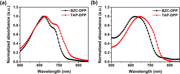 | ||
| Fig. 2 UV-Vis absorption spectra of BZC–DPP and TAP–DPP in (a) solution (10−5 M in chloroform) and (b) film state. | ||
| Polymer | λ max (nm) | λ onset (nm) |
E
g![[thin space (1/6-em)]](https://www.rsc.org/images/entities/char_2009.gif) opt
(eV) opt
(eV) |
E oxonset (V) | HOMOc (eV) | LUMOd (eV) | |
|---|---|---|---|---|---|---|---|
| Solution | Film | ||||||
| a Maximum absorption wavelength in the low-energy region. b E gopt = 1240/λonset (in film). c HOMO = −(4.8 − 0.33 + Eoxonset). d LUMO = HOMO + Egopt. | |||||||
| BZC–DPP | 621 | 623 | 735 | 1.69 | 0.87 | −5.34 | −3.65 |
| TAP–DPP | 629 | 647 | 765 | 1.62 | 1.01 | −5.48 | −3.86 |
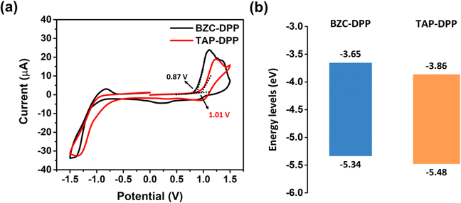
The electrochemical properties of both polymers were investigated by CV measurements as shown in Fig. 3a.64 The electrochemical properties were investigated by CV, using a reference electrode (Ag/Ag+) and a counter electrode platinum wire. The working electrodes were prepared by coating polymer solution on a Pt plate in an electrolyte solution (0.1 M tetrabutylammonium perchlorate in acetonitrile). The absolute energy level of ferrocene/ferrocenium (Fc/Fc+) is assumed to be 4.8 eV below the vacuum level. The external Fc/Fc+ redox standard E1/2 was determined to be 0.33 V versus Ag/Ag+ in acetonitrile by our electrochemical measuring system.
The HOMO energy level was also calculated from the onset potentials of oxidation. Using the equation HOMO = −(4.8 − 0.33 + Eoxonset), the HOMO energy levels of BZC–DPP and TAP–DPP were calculated to be −5.34 eV and −5.48 eV, respectively (Table 2 and Fig. 3b). The LUMO energy levels of BZC–DPP and TAP–DPP were calculated from the optical bandgaps. Using the equation LUMO = HOMO + Egopt, the LUMO energy levels were calculated to be −3.65 eV and −3.86 eV. TAP–DPP containing a strongly electron-withdrawing TAP with two aza structures showed much lower LUMO and HOMO energy levels compared with BZC–DPP containing BZC with only one aza structure. Lower LUMO energy levels should facilitate electron injection and improve material stability.51,65,66
DFT simulations
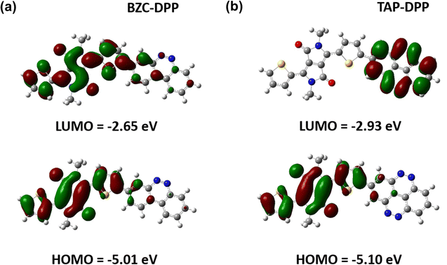
To further understand the theoretical frontier orbital distributions of polymers, one repeating unit with methyl side chains was simulated and calculated with DFT using B3LYP functional and the 6-31G* basis set as implemented in GAUSSIAN 09 as shown in Fig. 4. Both polymers exhibited obvious localized frontier orbitals. In the case of BZC–DPP, it was found that the HOMO and LUMO are mainly localized on DPP units due to their strong electron-accepting nature. On the other hand, the LUMO distribution contour of TAP–DPP was mainly localized on TAP units. It means that TAP units have stronger electron-withdrawing ability than BZC and DPP. Furthermore, HOMO and LUMO energy levels were also calculated from DFT calculations. TAP–DPP showed a lower HOMO and LUMO level (−5.10 eV and −2.93 eV) than BZC–DPP (−5.01 and −2.65 eV). It revealed that TAP units have stronger electron-withdrawing ability, which is consistent with the results from CV measurements.TENG application
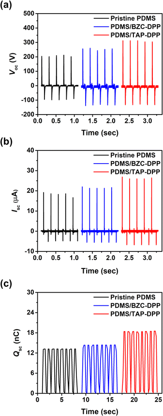
The working mechanism of TENG in the vertical contact-separation mode was based on the triboelectrification effect and electrostatic induction,67,68 as schematically illustrated in Fig. S5 (ESI†). When the triboelectric layers are separated, no charge is generated (Fig. S5a, ESI†). Once these layers are in contact, surface charge transfer takes place as a result of the triboelectrification effect (Fig. S5b, ESI†). The negative charges form at the surface of the dielectric layer and leave an equal amount of positive charges on the electrode, as shown in Fig. S5c (ESI†). As the generator starts to be released, the potential difference drives the surface charges redistribution until electrical equilibrium is reached, thereby generating electron flow in the external circuit (Fig. S5d, ESI†). When the triboelectric layers move back, electrons flow inversely from the electrode to the dielectric layer so as to achieve electrical equilibrium.The device structure and molecular structures of the TENG investigated herein are shown in Fig. 1, where the dielectric layer and the electrode layer were PDMS and Al films, respectively. The TENG without surface modification layer yielded a Voc of 212 V, Isc of 18.8 μA and Qsc of 13.2 nC, as shown in Fig. 5. Importantly, the output performance of the TENG was improved when using BZC–DPP as the surface modification layer, delivering a Voc of 264 V, Isc of 23.4 μA and Qsc of 14.4 nC (Fig. 5). Such an improvement can be attributed to the fact that the aza structures exhibit strong electron-withdrawing ability. Very encouragingly, the TENG output performance could be further boosted by using TAP–DPP as the surface modification layer, attaining a Voc of 328 V, Isc of 27 μA, and Qsc of 18.5 nC (Table 3 and Fig. 5). To the best of our knowledge, this is the first demonstration of a TENG using DPP-based conjugated polymers as the surface modification layer. The output characteristics of TENGs followed the same trend as the CV and DFT-simulated results (Fig. 3 and 4), which provided an important guideline for the development of conjugated polymers as the surface modification layer for TENGs.
To gain further insight into the performance improvement, AFM measurements of the PDMS film with different surface modification layers were demonstrated. The pristine PDMS (Fig. 6a) exhibited a smooth surface morphology, with a root mean square (RMS) roughness of =0.8 nm. The surface morphology was not altered noticeably by incorporating BZC–DPP and TAP–DPP as the surface modification layers (RMS roughness ≈ 0.4 nm; see Fig. 6b and c), presumably due to good film-forming properties of polymeric materials. SEM images of the PDMS layer with and without modification are also depicted in Fig. S6 (ESI†), and these results were consistent with those observed from AFM images shown in Fig. 6a–c. On the basis of the results, we suggested that the surface morphologies of BZC–DPP and TAP–DPP films could not be responsible for the observed performance improvement. A closer inspection of BZC–DPP and TAP–DPP layers with KPFM revealed that the TAP–DPP film possessed the work function (WF) of 4.89 eV (Fig. 6f), which was higher than those of pristine PDMS (4.67 eV; see Fig. 6d) and BZC–DPP (4.82 eV; see Fig. 6e). These results were in agreement with the electron-withdrawing properties of the molecules, as can be seen from CV and DFT-simulated results (Fig. 3 and 4). The relationship between the WF value of the dielectric layer and electrode on the transferred charge Δqc could be described as follows:69–72
 | (1) |
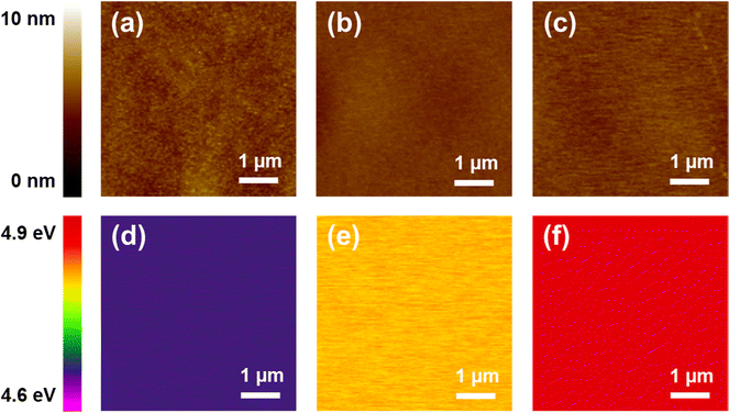 | ||
| Fig. 6 AFM topographic (upper) and KPFM images: (a and d) pristine PDMS, (b and e) PDMS/BZC-DPP, and (c and f) PDMS/TAP–DPP. | ||
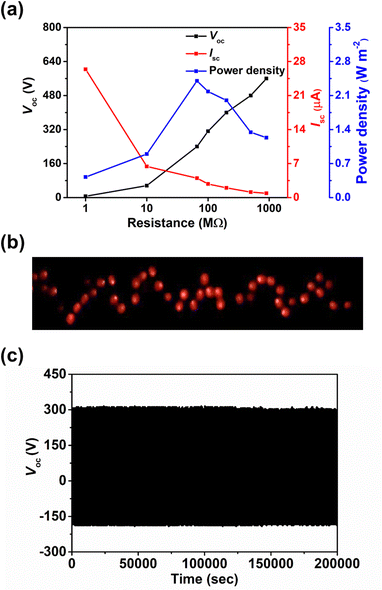
The effect of the thickness of surface modification layer on the TENG characteristics was also studied. It is interesting that increasing the thickness of BZC–DPP layer from 10 to 20 nm yielded inferior TENG characteristics, while only marginal changes on the output characteristics was observed in the case of TAP–DPP, as shown in Table S2 and Fig. S8 (ESI†). Although the underlying reason for such difference is still unclear, we speculate that this may be related to the more extended conjugation length of TAP–DPP when compared with BZC–DPP, which can favour charge transport and minimize the undesired charge accumulation and/or recombination effects.73,74 This effect becomes more important, especially when the film thickness increases.75 The detailed mechanism is worth further investigation that is still in progress. In addition, the load resistance dependent output characteristics of the TAP–DPP modified TENG were then investigated (Fig. 7a). The Voc increased with the increment of the load resistance while the Isc exhibited the reverse trend due to ohmic loss (Fig. 7a). Correspondingly, an instantaneous maximum power density of 2.4 W m−2 was achieved at a load resistance of 66 MΩ, as shown in Fig. 7a.3 Taking advantage of the high output characteristics of our TENG, 64 light-emitting diodes (LEDs) connected in series could be lit up instantaneously, as shown in Fig. 7b. More importantly, the resulting TENG also possessed good stability, exhibiting negligible degradation in Voc after continuous operation for 200![[thin space (1/6-em)]](https://www.rsc.org/images/entities/char_2009.gif) 000 cycles under ambient air conditions (25 °C, 50% relative humidity) shown in Fig. 7c. The Voc kept nearly identical (≈320 V) after exposure to high humidity (95% relative humidity) for 1 hour (Fig. S9, ESI†), affirming the superior stability of our TENG. We presumably attributed to this result to the good stability of TAP–DPP, as the polymer was hydrophobic (contact angle ≈ 79°, see Fig. S10, ESI†) and possessed superior oxidation stability owing to low-lying energy levels (Fig. 3).36,66 In addition to this, we also notice that the interfacial delamination issue was found to be negligible after continuous operation for 200
000 cycles under ambient air conditions (25 °C, 50% relative humidity) shown in Fig. 7c. The Voc kept nearly identical (≈320 V) after exposure to high humidity (95% relative humidity) for 1 hour (Fig. S9, ESI†), affirming the superior stability of our TENG. We presumably attributed to this result to the good stability of TAP–DPP, as the polymer was hydrophobic (contact angle ≈ 79°, see Fig. S10, ESI†) and possessed superior oxidation stability owing to low-lying energy levels (Fig. 3).36,66 In addition to this, we also notice that the interfacial delamination issue was found to be negligible after continuous operation for 200![[thin space (1/6-em)]](https://www.rsc.org/images/entities/char_2009.gif) 000 cycles (Fig. S11, ESI†), suggesting good adhesion of the TAP–DPP film to the PDMS surface. The surface morphology of the sample remained virtually unchanged even after 200
000 cycles (Fig. S11, ESI†), suggesting good adhesion of the TAP–DPP film to the PDMS surface. The surface morphology of the sample remained virtually unchanged even after 200![[thin space (1/6-em)]](https://www.rsc.org/images/entities/char_2009.gif) 000 cycles of continuous operation (Fig. S12, ESI†), confirming good adhesion between the TAP–DPP and PDMS films. It should be emphasized that the stability achieved herein was even superior to those of state-of-the-art TENGs based on conjugated polymers, as shown in Table S3 (ESI†). These results prove the viability of our strategy for the realization of high-performance and long-term stable TENGs that can act as potential energy harvesters for wearable electronics.
000 cycles of continuous operation (Fig. S12, ESI†), confirming good adhesion between the TAP–DPP and PDMS films. It should be emphasized that the stability achieved herein was even superior to those of state-of-the-art TENGs based on conjugated polymers, as shown in Table S3 (ESI†). These results prove the viability of our strategy for the realization of high-performance and long-term stable TENGs that can act as potential energy harvesters for wearable electronics.
Conclusions
DPP-based conjugated polymers, BZC–DPP and TAP–DPP, are demonstrated as the surface modification layer for TENGs. Compared with BZC–DPP, TAP–DPP with stronger electron-withdrawing ability yields superior TENG performance, delivering Voc of 328 V, Isc of 27 μA, and an instantaneous power density of 2.4 W m−2. More importantly, the TENG functionalized with TAP–DPP shows excellent stability even after continuous operation up to 200![[thin space (1/6-em)]](https://www.rsc.org/images/entities/char_2009.gif) 000 cycles. This work is the first demonstration of using DPP-based conjugated polymers as the surface modification layer for high-performance and long-term stable TENG. Our findings clearly elucidate that DPP-based conjugated polymers have great potential for TENG applications.
000 cycles. This work is the first demonstration of using DPP-based conjugated polymers as the surface modification layer for high-performance and long-term stable TENG. Our findings clearly elucidate that DPP-based conjugated polymers have great potential for TENG applications.
Author contributions
Kuang-Hao Cheng: data curation, formal analysis, writing – original draft. Cheng-You Tsai: data curation, formal analysis, writing – original draft. Yu-Han Wang: data curation, formal analysis. Shyam S. Pandey: formal analysis, investigation. Chih-Yu Chang: conceptualization, formal analysis, supervision, writing – review & editing, funding acquisition. Jyh-Chien Chen: conceptualization, formal analysis, supervision, writing – review & editing, funding acquisition.Conflicts of interest
There are no conflicts to declare.Acknowledgements
This work was financially supported by the National Science and Technology Council under grant Kyutech-NTUST-109-04, MOST 111-2628-E-011-005-MY3, MOST 110-2221-E-011-093-MY3, MOST 110-2628-E-011-005, and MOST 111-2622-E-011-010. The authors also thank Ms C.-H. Ho and Y.-N. Huang (National Taiwan Normal University) for NMR and Mass spectroscopy measurements.Notes and references
- C. Wu, A. C. Wang, W. Ding, H. Guo and Z. L. Wang, Adv. Energy Mater., 2019, 9, 1802906 CrossRef.
- G. Zhu, B. Peng, J. Chen, Q. Jing and Z. Lin Wang, Nano Energy, 2015, 14, 126–138 CrossRef CAS.
- Y. Wang, Y. Yang and Z. L. Wang, npj Flexible Electron., 2017, 1, 10 CrossRef.
- Z. L. Wang, Adv. Energy Mater., 2020, 10, 2000137 CrossRef CAS.
- S. Wang, Y. Xie, S. Niu, L. Lin, C. Liu, Y. S. Zhou and Z. L. Wang, Adv. Mater., 2014, 26, 6720–6728 CrossRef CAS PubMed.
- Y. Feng, Y. Zheng, S. Ma, D. Wang, F. Zhou and W. Liu, Nano Energy, 2016, 19, 48–57 CrossRef CAS.
- Y. Yu and X. Wang, Extreme Mech. Lett., 2016, 9, 514–530 CrossRef.
- Y. Liu, L. Wang, L. Zhao, X. Yu and Y. Zi, InfoMat, 2020, 2, 318–340 CrossRef CAS.
- J. S. Heo, J. Eom, Y.-H. Kim and S. K. Park, Small, 2018, 14, 1703034 CrossRef PubMed.
- A. Chen, C. Zhang, G. Zhu and Z. L. Wang, Adv. Sci., 2020, 7, 2000186 CrossRef CAS PubMed.
- G. Khandelwal, N. P. Maria Joseph Raj and S.-J. Kim, Adv. Energy Mater., 2021, 11, 2101170 CrossRef CAS.
- C.-C. Wang and C.-Y. Chang, J. Mater. Chem. C, 2020, 8, 4542–4548 RSC.
- J.-R. Yang, C.-J. Lee and C.-Y. Chang, J. Mater. Chem. A, 2021, 9, 4230–4239 RSC.
- Y.-H. Cheng, C.-J. Lee and C.-Y. Chang, Adv. Mater. Technol., 2021, 6, 2000985 CrossRef CAS.
- C.-Y. Chang, Y.-H. Cheng and C.-Y. Ho, J. Mater. Chem. A, 2022, 10, 22373–22389 RSC.
- W.-G. Kim, D.-W. Kim, I.-W. Tcho, J.-K. Kim, M.-S. Kim and Y.-K. Choi, ACS Nano, 2021, 15, 258–287 CrossRef CAS PubMed.
- J. Lowell and A. C. Rose-Innes, Adv. Phys., 1980, 29, 947–1023 CrossRef CAS.
- S. I. Park, D.-M. Lee, C. W. Kang, S. M. Lee, H. J. Kim, Y.-J. Ko, S.-W. Kim and S. U. Son, J. Mater. Chem. A, 2021, 9, 12560–12565 RSC.
- S. Cui, Y. Zheng, J. Liang and D. Wang, Chem. Sci., 2016, 7, 6477–6483 RSC.
- B.-Y. Lee, S.-U. Kim, S. Kang and S.-D. Lee, Nano Energy, 2018, 53, 152–159 CrossRef CAS.
- J. Xu, Y. Zou, A. Nashalian and J. Chen, Front. Chem., 2020, 8, 577327 CrossRef CAS PubMed.
- H. Bronstein, C. B. Nielsen, B. C. Schroeder and I. McCulloch, Nat. Rev. Chem., 2020, 4, 66–77 CrossRef CAS.
- H. Huang, L. Yang, A. Facchetti and T. J. Marks, Chem. Rev., 2017, 117, 10291–10318 CrossRef CAS PubMed.
- M. Kim, S. U. Ryu, S. A. Park, K. Choi, T. Kim, D. Chung and T. Park, Adv. Funct. Mater., 2020, 30, 1904545 CrossRef CAS.
- Q. Liu, S. E. Bottle and P. Sonar, Adv. Mater., 2020, 32, 1903882 CrossRef CAS PubMed.
- T. P. Kaloni, P. K. Giesbrecht, G. Schreckenbach and M. S. Freund, Chem. Mater., 2017, 29, 10248–10283 CrossRef CAS.
- O. Ostroverkhova, Chem. Rev., 2016, 116, 13279–13412 CrossRef CAS PubMed.
- X. Liu, G. Sun, Y. Gong, C.-F. Liu, S. Wang, S. Xu, X. Yang, L. Yang and W.-Y. Lai, Sci. China: Chem., 2022, 65, 1767–1774 CrossRef CAS.
- J. Y. Oh, S. Rondeau-Gagné, Y.-C. Chiu, A. Chortos, F. Lissel, G.-J. N. Wang, B. C. Schroeder, T. Kurosawa, J. Lopez, T. Katsumata, J. Xu, C. Zhu, X. Gu, W.-G. Bae, Y. Kim, L. Jin, J. W. Chung, J. B. H. Tok and Z. Bao, Nature, 2016, 539, 411–415 CrossRef CAS PubMed.
- J. Yang, Z. Zhao, S. Wang, Y. Guo and Y. Liu, Chem, 2018, 4, 2748–2785 CAS.
- J. Huang and G. Yu, Chem. Mater., 2021, 33, 1513–1539 CrossRef CAS.
- D. Li, Q. Wang, J. Huang, C. Wei, W. Zhang, L. Wang and G. Yu, ACS Appl. Mater. Interfaces, 2019, 11, 43416–43424 CrossRef CAS PubMed.
- C. Wei, W. Zhang, J. Huang, H. Li, Y. Zhou and G. Yu, Macromolecules, 2019, 52, 2911–2921 CrossRef CAS.
- Y. Yang, Z. Liu, G. Zhang, X. Zhang and D. Zhang, Adv. Mater., 2019, 31, 1903104 CrossRef CAS PubMed.
- Z.-F. Yao, J.-Y. Wang and J. Pei, Chem. Sci., 2021, 12, 1193–1205 RSC.
- S. Griggs, A. Marks, H. Bristow and I. McCulloch, J. Mater. Chem. C, 2021, 9, 8099–8128 RSC.
- A. F. Paterson, S. Singh, K. J. Fallon, T. Hodsden, Y. Han, B. C. Schroeder, H. Bronstein, M. Heeney, I. McCulloch and T. D. Anthopoulos, Adv. Mater., 2018, 1801079 CrossRef PubMed.
- Y. Ren, X. Yang, L. Zhou, J.-Y. Mao, S.-T. Han and Y. Zhou, Adv. Funct. Mater., 2019, 29, 1902105 CrossRef.
- L. Zhu, M. Zhang, W. Zhong, S. Leng, G. Zhou, Y. Zou, X. Su, H. Ding, P. Gu, F. Liu and Y. Zhang, Energy Environ. Sci., 2021, 14, 4341–4357 RSC.
- S. Luo, Z. Zeng, H. Wang, W. Xiong, B. Song, C. Zhou, A. Duan, X. Tan, Q. He, G. Zeng, Z. Liu and R. Xiao, Prog. Polym. Sci., 2021, 115, 101374 CrossRef CAS.
- Z.-P. Yu, K. Yan, W. Ullah, H. Chen and C.-Z. Li, ACS Appl. Polym. Mater., 2021, 3, 60–92 CrossRef CAS.
- H. Ma, Y. Chen, X. Li and B. Li, Adv. Funct. Mater., 2021, 31, 2101861 CrossRef CAS.
- D.-W. Zhang, M. Li and C.-F. Chen, Chem. Soc. Rev., 2020, 49, 1331–1343 RSC.
- R. Furue, K. Matsuo, Y. Ashikari, H. Ooka, N. Amanokura and T. Yasuda, Adv. Opt. Mater., 2018, 6, 1701147 CrossRef.
- L. Zhou, M. Yu, X. Chen, S. Nie, W.-Y. Lai, W. Su, Z. Cui and W. Huang, Adv. Funct. Mater., 2018, 28, 1705955 CrossRef.
- X.-C. Li, Y. Xue, W. Song, Y. Yan, J. Min, F. Liu, X. Liu, W.-Y. Lai and W. Huang, Research, 2020, 2020, 9075697 CAS.
- J. Zaumseil and H. Sirringhaus, Chem. Rev., 2007, 107, 1296–1323 CrossRef CAS PubMed.
- Z. Chen, M. Li, M. Hu, S. Wang, Z. Miao, S. Xu, C. Chen, H. Dong, W. Huang and R. Chen, J. Mater. Chem. C, 2020, 8, 2094–2101 RSC.
- G. Zhang, H. Yu, Y. Sun, W. Wang, Y. Zhao, L. Wang, L. Qiu and Y. Ding, J. Mater. Chem. C, 2021, 9, 633–639 RSC.
- G. Zhang, H. Yu, M. Sun, L. Tang and L. Qiu, Dyes Pigm., 2021, 194, 109660 CrossRef CAS.
- S.-W. Lee, S.-H. Chien, J.-C. Chen, S.-H. Wang, L.-Y. Wang, B.-H. Lai and C.-L. Wang, Org. Electron., 2019, 66, 136–147 CrossRef CAS.
- H.-C. Wu, J.-C. Chen and H.-Z. Lin, Macromolecules, 2015, 48, 4373–4381 CrossRef CAS.
- J.-C. Chen, H.-C. Wu, C.-J. Chiang, L.-C. Peng, T. Chen, L. Xing and S.-W. Liu, Polymer, 2011, 52, 6011–6019 CrossRef CAS.
- J.-C. Chen, H.-C. Wu, C.-J. Chiang, T. Chen and L. Xing, J. Mater. Chem. C, 2014, 2, 4835–4846 RSC.
- S. Ghosh, S. Shankar, D. S. Philips and A. Ajayaghosh, Mater. Today Chem., 2020, 16, 100242 CrossRef CAS.
- L. Shi, Y. Guo, W. Hu and Y. Liu, Mater. Chem. Front., 2017, 1, 2423–2456 RSC.
- C.-Y. Chang and C.-C. Wang, J. Mater. Chem. A, 2020, 8, 8593–8604 RSC.
- C. B. Nielsen, M. Turbiez and I. McCulloch, Adv. Mater., 2013, 25, 1859–1880 CrossRef CAS PubMed.
- C. K. Lo, R. M. W. Wolfe and J. R. Reynolds, Chem. Mater., 2021, 33, 4842–4852 CrossRef CAS.
- B. Carsten, F. He, H. J. Son, T. Xu and L. Yu, Chem. Rev., 2011, 111, 1493–1528 CrossRef CAS PubMed.
- C. Cordovilla, C. Bartolomé, J. M. Martínez-Ilarduya and P. Espinet, ACS Catal., 2015, 5, 3040–3053 CrossRef CAS.
- B. Xu, S.-A. Gopalan, A.-I. Gopalan, N. Muthuchamy, K.-P. Lee, J.-S. Lee, Y. Jiang, S.-W. Lee, S.-W. Kim, J.-S. Kim, H.-M. Jeong, J.-B. Kwon, J.-H. Bae and S.-W. Kang, Sci. Rep., 2017, 7, 45079 CrossRef CAS PubMed.
- A. Kim, D. H. Lee, H. A. Um, J. Shin, M. J. Cho and D. H. Choi, Polym. Chem., 2015, 6, 5478–5486 RSC.
- N. Elgrishi, K. J. Rountree, B. D. McCarthy, E. S. Rountree, T. T. Eisenhart and J. L. Dempsey, J. Chem. Educ., 2018, 95, 197–206 CrossRef CAS.
- J. T. E. Quinn, J. Zhu, X. Li, J. Wang and Y. Li, J. Mater. Chem. C, 2017, 5, 8654–8681 RSC.
- K. Takimiya, I. Osaka and M. Nakano, Chem. Mater., 2014, 26, 587–593 CrossRef CAS.
- Z. LináWang, Faraday Discuss., 2014, 176, 447–458 RSC.
- Y. Zi, C. Wu, W. Ding and Z. L. Wang, Adv. Funct. Mater., 2017, 27, 1700049 CrossRef.
- S. Matsusaka, H. Maruyama, T. Matsuyama and M. Ghadiri, Chem. Eng. Sci., 2010, 65, 5781–5807 CrossRef CAS.
- X. Cui and Y. Zhang, Nano Sel., 2020, 1, 461–470 CrossRef.
- J. Peng, S. D. Kang and G. J. Snyder, Sci. Adv., 2017, 3, eaap8576 CrossRef PubMed.
- S. Pan and Z. Zhang, Friction, 2019, 7, 2–17 CrossRef.
- B. Li, H. Yu, E. C. Montoto, Y. Liu, S. Li, K. Schwieter, J. Rodríguez-López, J. S. Moore and C. M. Schroeder, ACS Appl. Electron. Mater., 2019, 1, 7–12 CrossRef CAS.
- R. J. Kline and M. D. McGehee, J. Macromol. Sci., Polym. Rev., 2006, 46, 27–45 CrossRef CAS.
- S. Wilken, D. Scheunemann, S. Dahlström, M. Nyman, J. Parisi and R. Österbacka, Adv. Electron. Mater., 2021, 7, 2001056 CrossRef CAS.
Footnote |
| † Electronic supplementary information (ESI) available. See DOI: https://doi.org/10.1039/d2tc03551k |
| This journal is © The Royal Society of Chemistry 2022 |

