Hierarchical 3D porous carbon with facilely accessible Fe–N4 single-atom sites for Zn–air batteries†
Pingbo
Li
ab,
Xueqiang
Qi
*ac,
Lei
Zhao
b,
Junjie
Wang
b,
Meng
Wang
*c,
Minhua
Shao
 d,
Jun Song
Chen
b,
Rui
Wu
*b and
Zidong
Wei
 c
c
aCollege of Chemistry and Chemical Engineering, Chongqing University of Technology, Chongqing 400054, P. R. China. E-mail: xqqi@cqut.edu.cn
bSchool of Materials and Energy, University of Electronic Science and Technology of China, Chengdu, 611731, P. R. China. E-mail: ruiwu0904@uestc.edu.cn
cSchool of Chemistry and Chemical Engineering, Chongqing University, Chongqing 400044, P. R. China. E-mail: wmeng@cqu.edu.cn
dDepartment of Chemical and Biological Engineering, Hong Kong University of Science and Technology, Clear Water Bay, Kowloon, Hong Kong, China
First published on 14th October 2021
Abstract
Here, we report a highly efficient ORR electrocatalyst with Fe–N4 active sites uniformly dispersed on a three-dimensional (3D) interconnected porous nitrogen-doped carbon network synthesized by pyrolyzing SiO2@ZIF-8 composites loaded with iron salts. The as-prepared single-atom Fe 3D-ordered mesoporous carbon (SA-Fe-3DOMC) possesses a high specific surface area of 1357.8 m2 g−1 and a high Fe loading of 0.84 wt% as well. Benefiting from these favourable structural properties, SA-Fe-3DOMC exhibits a superior ORR half-wave potential (E1/2) of 0.901 V and negligible activity loss (only 3 mV) after 10![[thin space (1/6-em)]](https://www.rsc.org/images/entities/char_2009.gif) 000 cycles in alkaline media, surpassing the state-of-the-art Pt/C electrocatalyst. Particularly, an integrated zinc–air battery with SA-Fe-3DOMC as the air electrode shows a remarkable peak power density (140 mW cm−2) and a high specific capacity (786.6 mA h g−1), demonstrating great potential for practical application.
000 cycles in alkaline media, surpassing the state-of-the-art Pt/C electrocatalyst. Particularly, an integrated zinc–air battery with SA-Fe-3DOMC as the air electrode shows a remarkable peak power density (140 mW cm−2) and a high specific capacity (786.6 mA h g−1), demonstrating great potential for practical application.
Zinc–air batteries (ZABs) have received significant attention as promising next-generation batteries because of their high power density, high specific energy, low cost, environmental friendliness and good safety.1–3 However, the oxygen reduction reaction (ORR) at the cathode is subject to sluggish kinetics and usually requires high overpotentials.4 In order to speed up the ORR and make ZABs more energy-efficient, suitable electrocatalysts are always needed.5–7 Although precious metals and their alloys remain as outstanding candidates for catalyzing the ORR, their practical applications have been significantly hampered by the prohibitive cost and scarcity of precious metals.8–12 Therefore, it is important to develop high-performance inexpensive catalysts to replace precious metals.13,14
To date, Fe single-atom catalysts (SACs) dispersed as Fe–N4 active sites on a porous carbon matrix have been regarded as one of the most efficient ORR electrocatalysts owing to their high activity, durable stability and maximum atom utilization.15–17 In general, Fe SACs can be obtained by direct pyrolysis of mixtures of N- and C-containing precursors and Fe salts, followed by acid washing.18,19 However, iron species are prone to agglomerate during the pyrolysis process, forming iron-based nanoparticles or clusters that are difficult to remove, thus blocking the formation of Fe–N4 active sites.20 Moreover, inaccessible pores will be generated owing to the random mixing of the N–C precursors and Fe salts. This leads to some buried Fe–N4 active sites that cannot be exposed at the three-phase interface, thus reducing the utilization of Fe SACs.21–24 Thus, an ideal Fe SAC should possess highly accessible Fe–N4 active sites and a porous network that can facilitate the transport of electrons, oxygen and water.25 A three dimensional (3D) ordered porous architecture with open channels would be suitable to maximize the accessibility of active sites, but suffers from the limitation of a low specific surface area and cannot support more Fe–N4 active sites.26,27 Considering these issues collectively, a 3D-ordered large-pore structure with suitable micropores and mesopores will be highly desirable, which facilitates the exposure of active sites and mass transfer.28–30
Herein, we have designed 3D-ordered porous nitrogen-doped carbon with accessible Fe–N4 active sites as an efficient electrocatalyst for the ORR. Remarkably, the as-prepared SA-Fe-3DOMC possessed a high specific surface area of 1357.8 m2 g−1 and a high Fe loading (0.84 wt%). The electrochemical results demonstrated that SA-Fe-3DOMC exhibited excellent ORR catalytic activity and stability, with E1/2 increased to 0.901 V while the current almost remained similar after 10![[thin space (1/6-em)]](https://www.rsc.org/images/entities/char_2009.gif) 000 potential cycles from 0.6 V to 1 V in alkaline media. Furthermore, an integrated ZAB with SA-Fe-3DOMC as the air electrode showed a remarkable peak power density (140 mW cm−2) and a high specific capacity (786.6 mA h g−1), demonstrating great potential for practical application.
000 potential cycles from 0.6 V to 1 V in alkaline media. Furthermore, an integrated ZAB with SA-Fe-3DOMC as the air electrode showed a remarkable peak power density (140 mW cm−2) and a high specific capacity (786.6 mA h g−1), demonstrating great potential for practical application.
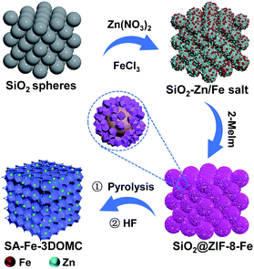
The synthetic procedure of the SA-Fe-3DOMC catalysts is illustrated in Scheme 1. Briefly, silica nanospheres with a size of 180–200 nm were first modified with Fe3+ (FeCl3·6H2O) and Zn2+ (Zn(NO3)2·6H2O) (Fig. S1a, ESI†). The subsequent in situ growth of ZIF-8 embedded the silica nanospheres into the MOF precursors (Fig. S1b, ESI†).26 After carbonization at 900 °C and HF etching, SA-Fe-3DOMC was obtained, showing a honeycomb-like structure and uniform pores with a diameter ranging from 180 to 200 nm (Fig. 1a, b, S1c and d, ESI†), matching well with the size of silica templates. Consistently, a well-defined interconnected macroporous structure with a 10 nm-thick wall was identified by transmission electron microscopy (TEM) (Fig. 1c). Moreover, Fig. 1d reveals that no nanoparticles were detected in the high-angle annular dark field-scanning transmission electron microscope (HAADF-STEM) observation. Elemental mapping images clearly demonstrated the homogeneous distribution of C, N, O and Fe in SA-Fe-3DOMC (Fig. 1e), indicating that iron atoms exist in the carbon matrix as atomically dispersed actives sites. Moreover, the HAADF-STEM image of SA-Fe-3DOMC exhibited that abundant and isolated Fe atoms with brighter spots were indeed atomically dispersed on the porous carbon matrix (Fig. 1f), which was a piece of strong evidence for the successful synthesis of single atoms.27,28
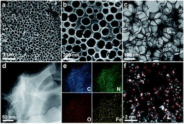 | ||
| Fig. 1 (a and b) SEM images of SA-Fe-3DOMC. (c) TEM image of SA-Fe-3DOMC. (d) HAADF-STEM image of SA-Fe-3DOMC and (e) corresponding elemental images. (f) AC-HAADF-STEM image of SA-Fe-3DOMC. | ||
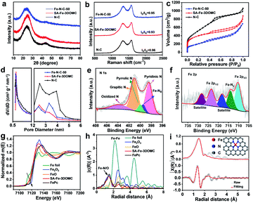
The XRD patterns of N–C, SA-Fe-3DOMC and Fe–N–C-50 showed almost the same diffraction peaks centered at around 24.7° and 43.6° (Fig. 2a), which are assigned to the (002) and (101) lattice planes of graphitic carbon, respectively.31,32 Remarkably, no peaks belonging to Fe and Zn species were observed, confirming the absence of crystalline Fe and Zn particles in SA-Fe-3DOMC. The Fe loading amount of SA-Fe-3DOMC was measured to be 0.84 wt% by inductively coupled plasma-mass spectrometry (ICP-MS). The Raman spectra of the three samples exhibited two prominent peaks at 1340 cm−1 and 1590 cm−1, which are ascribed to the D-band (sp3 disordered carbon) and G-band (sp2 graphitic carbon), respectively (Fig. 2b).33 The intensity ratio ID/IG values for N–C, SA-Fe-3DOMC and Fe–N–C-50 were calculated to be 0.96, 0.93 and 0.95, indicating that SA-Fe-3DOMC possessed a much higher graphitization degree than the other two counterparts.
The pore structures of the as-synthesized catalysts were further characterized by N2 adsorption–desorption measurements. All catalysts presented a characteristic type IV isotherm, suggesting the presence of abundant mesopores in the samples. Furthermore, a rapid adsorption of N2 at relatively low pressure (P/P0 < 0.1) was observed, indicating that micropores can be speculated in the sample (Fig. 2c).34,35 With the increased number of Fe salts, the specific surface area dramatically decreased from 1681.6 m2 g−1 for N–C to 1357.8 m2 g−1 for SA-Fe-3DOMC and to 629.7 m2 g−1 for Fe–N–C-50. Moreover, the pore distribution revealed two sharp peaks at 0.565 nm and 2 to 4 nm (Fig. 2d), implying that a large number of micropores and mesopores were formed,36 owing to the evaporation of Zn species and the catalytic effect of Fe salts, respectively.37,38 Notably, the higher specific surface area and abundant pores facilitate the exposure of more Fe–Nx active sites, resulting in better ORR catalytic performance.
The elemental chemical state of the obtained catalyst surface was analysed by X-ray photoelectron spectroscopy (XPS). The XPS survey spectrum of SA-Fe-3DOMC presented showed the presence of C (89.28 at%), N (4.63 at%), O (5.04 at%), and Fe (1.05 at%) (Fig. S2a, ESI†). The C 1s spectrum of SA-Fe-3DOMC was resolved into C–C (∼284.7 eV), C–N (∼286.2 eV) and C–O (∼289.0 eV), suggesting that heteroatom N was successfully doped into the porous carbon network (Fig. S3, ESI†).39 The high-resolution N1s spectra of N–C, SA-Fe-3DOMC and Fe–N–C-50 can be deconvoluted into pyridinic-N (∼398.5 eV), pyrrolic-N (∼400.1 eV), graphitic-N (∼401.1 eV) and oxidized-N (∼403.9 eV). In addition, a peak at 399.6 eV assigned to Fe–Nx species was observed in both SA-Fe-3DOMC and Fe–N–C-50 (Fig. 2e, S2b and c, ESI†).28 Furthermore, SA-Fe-3DOMC possessed the highest proportion of pyridinic N and graphitic N compared to the other two counterparts (Fig. S4, ESI†), which is beneficial for regulating the properties of the Fe–N–C catalyst.39 The Fe 2p high-resolution spectra of SA-Fe-3DOMC and Fe–N–C-50 can be convolved into Fe 2p3/2 (710.0 eV) and Fe 2p1/2 (723.7 eV), with peaks around 725.5 eV and 716.1 eV classified as the satellite peaks of Fe, while the peak at 713.2 eV could be assigned to Fe–Nx species (Fig. 2f and S2d, ESI†).40,41 Linear fitting curve of Fe foil, FeO, Fe2O3 and SA-Fe-3DOMC were derived from corresponding Fe K-edge X-ray absorption near edge structure (XANES) position. The iron K-edge XANES position of SA-Fe-3DOMC was located close to that of FeO (Fig. 2g and S9, ESI†), indicating that the valence state of Fe in SA-Fe-3DOMC was close to +2.42,43 The Fourier-transform (FT) of k3-weighted extended X-ray absorption fine structure (EXAFS) revealed a predominant peak at 1.50 Å in R space for SA-Fe-3DOMC (Fig. 2h), ascribed to the Fe–N(O) coordination. No Fe–Fe coordination peak (at 2.2 Å) was observed for SA-Fe-3DOMC, further demonstrating the absence of metallic Fe.44 The EXAFS fitting results were used to indicate the coordination environments of Fe in SA-Fe-3DOMC (Fig. 2i and Table S1, ESI†), which revealed that the Fe atoms in SA-Fe-3DOMC were coordinated with four N atoms, indicating a high probability that the active sites in SA-Fe-3DOMC could be Fe–N4.45
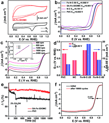
The electrocatalytic activity of NC, SA-Fe-3DOMC and Fe–N–C-50 was first evaluated by cyclic voltammetry (CV). Apparently, the CV curves of all samples showed obvious oxygen reduction peaks under O2-saturated conditions (Fig. 3a, S5a and b, ESI†), and a more positive oxygen reduction peak of SA-Fe-3DOMC was observed, indicating a superior catalytic activity. Moreover, linear sweep voltammetry (LSV) curves recorded by using a rotating disk electrode (RDE) at 1600 rpm were used to investigate the ORR activities in O2-saturated 0.1 M KOH solution. The SA-Fe-3DOMC catalyst exhibited the highest ORR catalytic activity with an onset potential (Eonset) of 0.994 V, a E1/2 of 0.901 V and a diffusion-limited current densities of 5.696 mA cm−2, which were much higher than those of commercial Pt/C (0.946 V, 0.855 V, and 5.228 mA cm−2), Fe–N–C-50 (0.955 V, 0.868 V, and 5.608 mA cm−2) and NC (0.876 V, 0.781 V, and 4.982 mA cm−2) (Fig. 3b). To further explore the ORR pathway of SA-Fe-3DOMC, LSV curves were recorded at different rotation speeds (from 400 to 2400 rpm). As depicted in Fig. 3c, the Koutecky–Levich (K–L) plots of SA-Fe-3DOMC showed good linearity and a similar slope, demonstrating that the ORR takes place on the SA-Fe-3DOMC catalyst in a similar way at different potentials. The average electron transfer number of SA-Fe-3DOMC calculated from the K–L plot at 0.4–0.6 V was about 3.7, reflecting an approximate 4e− oxygen reduction pathway (inset of Fig. 3c). RRDE measurements demonstrated very low H2O2 yields (3.4–5.1%) and electron transfer numbers in the range of 3.7–3.8 for the SA-Fe-3DOMC catalyst in the potential range from 0.2 to 0.8 V (Fig. S6a and b, ESI†). Fig. 3d further shows the kinetic current density (jk) of N–C, SA-Fe-3DOMC, Fe–N–C-50 and commercial Pt/C. Remarkably, the jk of SA-Fe-3DOMC reached as high as 18.70 mA cm−2 at 0.85 V, and it was almost 2.8-fold that of commercial Pt/C (6.63 mA cm−2).
In addition, the methanol crossover effects on SA-Fe-3DOMC and Pt/C catalysts were measured in O2-saturated 0.1 M KOH at 0.6 V. With the addition of 2% (v/v) methanol, a sharp decay in current density was immediately detected for Pt/C (Fig. 3e). In contrast, there was no noticeable variation in current density for SA-Fe-3DOMC, showing a better tolerance to methanol crossover. The ORR stability of SA-Fe-3DOMC and commercial Pt/C was further investigated by an accelerated durability test (ADT). As illustrated in Fig. 3f, the E1/2 of SA-Fe-3DOMC displayed a negligible negative shift of only 3 mV after 10![[thin space (1/6-em)]](https://www.rsc.org/images/entities/char_2009.gif) 000 potential cycles from 0.6 V to 1 V. In comparison, the commercial Pt/C showed a severe loss of 12 mV (Fig. S7, ESI†). As shown in Fig. S8,† the morphology and corresponding elemental distribution of SA-Fe-3DOMC before and after 10
000 potential cycles from 0.6 V to 1 V. In comparison, the commercial Pt/C showed a severe loss of 12 mV (Fig. S7, ESI†). As shown in Fig. S8,† the morphology and corresponding elemental distribution of SA-Fe-3DOMC before and after 10![[thin space (1/6-em)]](https://www.rsc.org/images/entities/char_2009.gif) 000 cycles remain almost unchanged, further confirming the robust properties of SA-Fe-3DOMC. These results suggested that the SA-Fe-3DOMC catalyst has superior electrocatalytic activity and durability in alkaline medium, making it very attractive as a cost-effective electrocatalyst alternative to replace Pt-based counterparts for the ORR.
000 cycles remain almost unchanged, further confirming the robust properties of SA-Fe-3DOMC. These results suggested that the SA-Fe-3DOMC catalyst has superior electrocatalytic activity and durability in alkaline medium, making it very attractive as a cost-effective electrocatalyst alternative to replace Pt-based counterparts for the ORR.
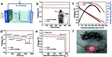
To further reveal the potential of the SA-Fe-3DOMC electrocatalyst for practical applications, a liquid ZAB was assembled, where carbon paper loaded with SA-Fe-3DOMC and a gas diffusion layer was used as the air electrode (Fig. 4a). Such a battery afforded a stable open-circuit voltage (1.48 V), which was more positive than that of the Pt/C-based battery (1.37 V) (Fig. 4b), confirming outstanding catalytic performance. As shown in Fig. 4c, the battery with SA-Fe-3DOMC exhibited a peak power density of 140 mW cm−2, which was superior to that with Pt/C (124.5 mW cm−2). A typical constant current discharge test also was performed at different current densities (Fig. 4d). Apparently, the voltage gap between SA-Fe-3DOMC and commercial Pt/C widened with the increase of current density, suggesting that the well-designed interconnected 3D nanoporous structure facilitated the mass transfer, especially at higher current densities.46 When normalized to the consumed Zn during a long-term constant current discharge process at 10 mA cm−2, the SA-Fe-3DOMC battery exhibited a much higher specific capacity with a value of 786.6 mA h g−1, which means that the utilization of catalysts is equal to 95.9% since the theoretical capacity is 820 mA h g−1 (Fig. 4e). Moreover, the SA-Fe-3DOMC-based battery can provide electrical energy for 8 light-emitting diodes (LEDs) (Fig. 4f), demonstrating great potential for practical applications.
In summary, we designed and synthesized a SA-Fe-3DOMC electrocatalyst with high ORR catalytic activity, using a SiO2-embedded Zn-MOF assisted strategy. The achieved SA-Fe-3DOMC showed an excellent E1/2 of 0.901 V and a high durability of only 3 mV decrease after 10![[thin space (1/6-em)]](https://www.rsc.org/images/entities/char_2009.gif) 000 potential cycles, surpassing the state-of-the-art Pt/C in alkaline medium. For ZAB applications, the as-prepared SA-Fe-3DOMC electrocatalyst also exhibited an outstanding peak power density of 140 mW cm2 and a superior specific capacity of 786.6 mA h g−1. Collectively, the hierarchical pores generated by SiO2 and Zn species as porogens allowed the facile access of the single-atom active sites, providing effective strategies not only for seeking alternatives to Pt/C catalysts but also to develop more catalysts for various energy conversion devices, such as CO2 reduction, water splitting, and N2 fixation.
000 potential cycles, surpassing the state-of-the-art Pt/C in alkaline medium. For ZAB applications, the as-prepared SA-Fe-3DOMC electrocatalyst also exhibited an outstanding peak power density of 140 mW cm2 and a superior specific capacity of 786.6 mA h g−1. Collectively, the hierarchical pores generated by SiO2 and Zn species as porogens allowed the facile access of the single-atom active sites, providing effective strategies not only for seeking alternatives to Pt/C catalysts but also to develop more catalysts for various energy conversion devices, such as CO2 reduction, water splitting, and N2 fixation.
Conflicts of interest
There are no conflicts to declare.Acknowledgements
This work was financially supported by the National Key Research and Development Program (2018YFB1502503), Sichuan Science and Technology Program (2020YJ0299), Projects of International Cooperation and Exchanges NSFC (21761162015) and Science and Technology Research Program of Chongqing Municipal Education Commission (KJQN201801125).References
- F. Meng, H. Zhong, D. Bao, J. Yan and X. Zhang, J. Am. Chem. Soc., 2016, 138, 10226–10231 CrossRef CAS.
- W. Wang, M. Tang, Z. Zheng and S. Chen, Adv. Energy Mater., 2019, 9, 1803628 CrossRef.
- J. Pan, Y. Y. Xu, H. Yang, Z. Dong, H. Liu and B. Y. Xia, Adv. Sci., 2018, 51700691 Search PubMed.
- D. Wang, H. Xu, P. Yang, X. Lu, J. Ma, R. Li, L. Xiao, J. Zhang and M. An, J. Mater. Chem. A, 2021, 9, 13678–13687 RSC.
- P. Wei, X. G. Li, Z. M. He, X. P. Sun, Q. R. Liang, Z. Y. Wang, C. Fang, Q. Li, H. Yang, J. T. Han and Y. H. Huang, Chem. Eng. J., 2021, 422, 130134 CrossRef CAS.
- H. Luo, W. J. Jiang, S. Niu, X. Zhang, Y. Zhang, L. P. Yuan, C. He and J. S. Hu, Small, 2020, 16, 2001171 CrossRef CAS.
- X. Li, Y. Liu, H. Chen, M. Yang, D. Yang, H. Li and Z. Lin, Nano Lett., 2021, 21, 3098–3105 CrossRef CAS PubMed.
- I. S. Amiinu, X. Liu, Z. Pu, W. Li, Q. Li, J. Zhang, H. Tang, H. Zhang and S. Mu, Adv. Funct. Mater., 2018, 28, 104670 CrossRef.
- Q. C. Xu, H. Jiang, Y. H. Li, D. Liang, Y. J. Hu and C. Z. Li, Appl. Catal., B, 2019, 256, 117893 CrossRef CAS.
- R. Wu, Y. Song, X. Huang, S. Chen, S. Ibraheem, J. Deng, J. Li, X. Qi and Z. Wei, J. Power Sources, 2018, 401, 287–295 CrossRef CAS.
- L. Zhao, R. Wu, J. Wang, Z. Li, X. Wei, J. S. Chen and Y. Chen, J. Energy Chem., 2021, 60, 61–74 CrossRef.
- Y.-N. Chen, Y. Guo, H. Cui, Z. Xie, X. Zhang, J. Wei and Z. Zhou, J. Mater. Chem. A, 2018, 6, 9716–9722 RSC.
- P. T. Liu, D. Q. Gao, W. Xiao, L. Ma, K. Sun, P. X. Xi, D. S. Xue and J. Wang, Adv. Funct. Mater., 2018, 28, 1706928 CrossRef.
- M. Zhang, Q. Dai, H. Zheng, M. Chen and L. Dai, Adv. Mater., 2018, 30, 1705431 CrossRef.
- X. Luo, X. Wei, H. Wang, W. Gu, T. Kaneko, Y. Yoshida, X. Zhao and C. Zhu, Nano-Micro Lett., 2020, 12, 163 CrossRef CAS PubMed.
- Z. Zhang, X. Gao, M. Dou, J. Ji and F. Wang, J. Mater. Chem. A, 2017, 5, 1526–1532 RSC.
- Y. Yan, H. Y. Cheng, Z. H. Qu, R. Yu, F. Liu, Q. W. Ma, S. Zhao, H. Hu, Y. Cheng, C. Y. Yang, Z. F. Li, X. Wang, S. Y. Hao, Y. Y. Chen and M. K. Liu, J. Mater. Chem. A, 2021, 9, 19489–19507 RSC.
- J. Zhang, X. Dong, W. Xing, Y. Luo, Y. Chen, Y. Xue, C. Zhang, J. Chen, G. Wang and R. Wang, Chem. Eng. J., 2021, 420, 129938 CrossRef CAS.
- D. Wang, H. Xu, P. Yang, L. Xiao, L. Du, X. Lu, R. Li, J. Zhang and M. An, J. Mater. Chem. A, 2021, 9, 9761–9770 RSC.
- Y. Qiao, P. Yuan, Y. Hu, J. Zhang, S. Mu, J. Zhou, H. Li, H. Xia, J. He and Q. Xu, Adv. Mater., 2018, 30, 1804504 CrossRef.
- Y. C. Guo, L. Feng, C. C. Wu, X. M. Wang and X. Zhang, J. Catal., 2020, 390, 213–223 CrossRef CAS.
- R. Jiang, L. Li, T. Sheng, G. Hu, Y. Chen and L. Wang, J. Am. Chem. Soc., 2018, 140, 11594–11598 CrossRef CAS PubMed.
- H. W. Liang, W. Wei, Z. S. Wu, X. Feng and K. Mullen, J. Am. Chem. Soc., 2013, 135, 16002–16005 CrossRef CAS PubMed.
- Y. Li, J. Gao, F. Zhang, Q. Qian, Y. Liu and G. Zhang, J. Mater. Chem. A, 2018, 6, 15523–15529 RSC.
- S. Lee, D. H. Kwak, S. B. Han, Y. W. Lee, J. Y. Lee, I. A. Choi, H. S. Park, J. Y. Park and K. W. Park, ACS Catal., 2016, 6, 5095–5102 CrossRef CAS.
- A. I. Douka, Y. Xu, H. Yang, S. Zaman, Y. Yan, H. Liu, M. A. Salam and B. Y. Xia, Adv. Mater., 2020, 32, 2002170 CrossRef CAS.
- Y. J. Deng, B. Chi, X. L. Tian, Z. M. Cui, E. S. Liu, Q. Y. Jia, W. J. Fan, G. H. Wang, D. Dang, M. S. Li, K. T. Zang, J. Luo, Y. F. Hu, S. J. Liao, X. L. Sun and S. Mukerjee, J. Mater. Chem. A, 2019, 7, 5020–5030 RSC.
- X. Zhang, X. Han, Z. Jiang, J. Xu, L. Chen, Y. Xue, A. Nie, Z. Xie, Q. Kuang and L. Zheng, Nano Energy, 2020, 71, 104547 CrossRef CAS.
- Y. Yan, P. Zhang, Z. Qu, M. Tong, S. Zhao, Z. Li, M. Liu and Z. Lin, Nano Lett., 2020, 20, 7662–7669 CrossRef CAS PubMed.
- M. Liu, P. Zhang, Z. Qu, Y. Yan, C. Lai, T. Liu and S. Zhang, Nat. Commun., 2019, 10, 3917 CrossRef.
- G. Gan, X. Li, L. Wang, S. Fan, J. Mu, P. Wang and G. Chen, ACS Nano, 2020, 14, 9929–9937 CrossRef CAS.
- J. Han, X. Meng, L. Lu, J. Bian, Z. Li and C. Sun, Adv. Funct. Mater., 2019, 29, 1808872 CrossRef CAS.
- Y. Wang, R. Gan, H. Liu, M. Dirican, C. Wei, C. Ma, J. Shi and X. Zhang, J. Mater. Chem. A, 2021, 9, 2764–2774 RSC.
- B. Chen, X. He, F. Yin, H. Wang, D.-J. Liu, R. Shi, J. Chen and H. Yin, Adv. Funct. Mater., 2017, 27, 1700795 CrossRef.
- B. Li, Y. Yan, C. Shen, Y. Yu, Q. Wang and M. Liu, Nanoscale, 2018, 10, 16217–16230 RSC.
- Q. Y. Zhou, Z. Zhang, J. J. Cai, B. Liu, Y. L. Zhang, X. F. Gong, X. L. Sui, A. P. Yu, L. Zhao, Z. B. Wang and Z. W. Chen, Nano Energy, 2020, 71, 104592 CrossRef CAS.
- Y. Zhou, Y. Yu, D. Ma, A. C. Foucher, L. Xiong, J. Zhang, E. A. Stach, Q. Yue and Y. Kang, ACS Catal., 2020, 11, 74–81 CrossRef.
- G. Chen, P. Liu, Z. Liao, F. Sun, Y. He, H. Zhong, T. Zhang, E. Zschech, M. Chen, G. Wu, J. Zhang and X. Feng, Adv. Mater., 2020, 32, 1907399 CrossRef CAS.
- H. Zhang, S. Hwang, M. Wang, Z. Feng, S. Karakalos, L. Luo, Z. Qiao, X. Xie, C. Wang, D. Su, Y. Shao and G. Wu, J. Am. Chem. Soc., 2017, 139, 14143–14149 CrossRef CAS PubMed.
- X. Xie, L. Peng, H. Yang, G. I. N. Waterhouse, L. Shang and T. Zhang, Adv. Mater., 2021, 33, 2101038 CrossRef CAS PubMed.
- L. Lin, Q. Zhu and A. W. Xu, J. Am. Chem. Soc., 2014, 136, 11027–11033 CrossRef CAS.
- K. Yuan, D. Lutzenkirchen-Hecht, L. Li, L. Shuai, Y. Li, R. Cao, M. Qiu, X. Zhuang, M. K. H. Leung, Y. Chen and U. Scherf, J. Am. Chem. Soc., 2020, 142, 2404–2412 CrossRef CAS.
- Y. Yan, S. Liang, X. Wang, M. Zhang, S.-M. Hao, X. Cui, Z. Li and Z. Lin, Proc. Natl. Acad. Sci. U. S. A., 2021, 40, 118 Search PubMed.
- Z. Zhang, J. Sun, F. Wang and L. Dai, Angew. Chem., Int. Ed. Engl., 2018, 57, 9038–9043 CrossRef CAS PubMed.
- J. Chen, H. Li, C. Fan, Q. Meng, Y. Tang, X. Qiu, G. Fu and T. Ma, Adv. Mater., 2020, 32, 2003134 CrossRef CAS.
- M. G. Park, D. U. Lee, M. H. Seo, Z. P. Cano and Z. Chen, Small, 2016, 12, 2707–2714 CrossRef CAS.
Footnote |
| † Electronic supplementary information (ESI) available. See DOI: 10.1039/d1ta08050d |
| This journal is © The Royal Society of Chemistry 2022 |

