Two-dimensional materials for electrocatalysis and energy storage applications
Tingting
Li
 a,
Tianyun
Jing
b,
Dewei
Rao
 *b,
Stefanos
Mourdikoudis
 c,
Yunpeng
Zuo
 *d and
Mengye
Wang
 *ef
*ef
aInstitute of Surface Micro and Nano Materials, Xuchang University, Xuchang, Henan 461002, People's Republic of China
bSchool of Materials Science and Engineering, Jiangsu University, Zhenjiang 212013, People's Republic of China. E-mail: dewei@ujs.edu.cn
cDepartment of Inorganic Chemistry, University of Chemistry and Technology Prague, Technicka 5, Prague 6, 166 28 Czech Republic
dRegional Centre of Advanced Technologies and Materials, Czech Advanced Technology and Research Institute, Palacký University, 77900 Olomouc, Czech Republic. E-mail: ypzuo01@gmail.com
eSchool of Materials, Sun Yat-Sen University, Shenzhen 518107, China
fState Key Laboratory of Optoelectronic Materials and Technologies, Sun Yat-Sen University, Guangzhou 510275, China. E-mail: wangmengye@mail.sysu.edu.cn
First published on 18th October 2022
Abstract
Since the discovery and widespread application of graphene, a plethora of various 2D materials continue to emerge and attract a lot of interest in materials science. These materials comprise a vast family with several different compositions and properties. In this review, 2D materials beyond graphene used in electrocatalysis and energy storage are discussed in detail. In particular, the range of properties related to the electronic and structural features of such materials are explored, and relevant recent results are analyzed. Synergistic phenomena and mechanisms leading to improved electrochemical performance are described. A brief overview of the unique traits of the category of materials classified as 2D materials is first given, with a focus on the recent design and application breakthroughs in the fields of energy storage and electrocatalysis. Once the current level of development on the use of such materials is understood, future challenges and prospects are separately outlined to facilitate effective material design and further promote the exploitation potential of the materials under discussion in the domains of energy conversion and storage.
1. Introduction
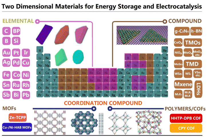
Since the discovery of graphene in 2003, a multitude of additional two-dimensional (2D) materials, ranging from insulators and semiconductors to conductors, have been intensively studied as a result of their unique properties that differ from their bulk counterparts.1–5 In general, the 2D structure with atomic-level thickness endows such materials with a large surface area, favorable charge transfer plane, and special quantum-size effect. The distinctive physicochemical, optical and electronic properties, high thermal conductivity and mechanical strength, as well as the electron confinement effect make the materials under discussion attractive for diverse applications, including photo/electrocatalysis, energy storage and transistors and sensors, among others.3–10 To date, hundreds of 2D materials besides graphene have been successfully prepared to form a gigantic 2D library, such as 2D transition metal dichalcogenides (TMDs), 2D layered double hydroxides (LDHs), 2D metal–organic frameworks (MOFs), 2D transition metal carbides/carbonitrides (MXenes), transition metal oxides (TMOs), graphitic carbon nitride, phosphorus, silicene, hexagonal boron nitride, 2D metals and 2D perovskites, as well as 2D polymers and covalent organic compounds (COFs).10–20 All the relevant 2D materials are summarized and shown in Fig. 1. Notably, the rapid development of artificial intelligence and computational simulation techniques provides strong support for novel materials’ design, fabrication, and exploitation. Many researchers use interrelated technologies to predict the features of the targeted materials, which facilitates expansion of the production of several different categories, components and structures of 2D materials.21–28 At the same time, a range of emerging technologies guides researchers to carry out the design and application of complex heterostructures with multiple layers consisting of distinct components with different combinations. More specifically, the compositional diversity and structural tunability of these 2D materials make them promising for numerous technological applications. Among all the 2D materials, the close dependence of the arising properties on their composition makes it feasible to set the most suitable targeted material priorities each time. To further meet specific requirements for electrocatalysis and energy storage applications, we correspondingly summarize herein the main characteristics of the intrinsic composition, synthetic and functional modification methods of 2D materials. These approaches include surface functionalization,11–17 mechanical or chemical exfoliation,6,18–22 forming heterostructures,23–26 heteroatoms doping,27–30 defects creation31,32 and valence engineering.4,22,23 Importantly, the rapidly rising and wide applications in the realms of electrocatalysts and energy storage have recently attracted extensive attention due to ever-increasing energy consumption issues; the involved energy storage and conversion devices include supercapacitors, batteries, fuel cells and water-splitting apparatus.33–38In this review, we focus on the recent advances in new families of 2D materials with rational design and their applications in electrocatalysis and energy storage. 2D materials are composed of elements which are mainly distributed in the different groups highlighted in the periodic table in Fig. 1. With the advancement of theoretical predictions and new technologies, 2D monoelemental materials with multi-layer stacking and different rotation angles between layers are continuously being developed, and they exhibit interesting novel properties, while unprecedented features are discovered at times. Besides the 2D monoelemental materials, most of the 2D materials are formed by transition metals from groups IVB to VIII, due to their rich valence bond coordination ability. Constructing heterojunctions based on 2D compounds can result in the formation of several different combinations with expanding applications in numerous fields. These include especially electrocatalysis, energy storage and electronic informatics (Scheme 1). Hence, we elaborate on the fundamental properties of these 2D materials and discuss the activity origin or mechanisms responsible for making these materials suitable for such applications.
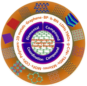 | ||
| Scheme 1 Schematic representation of the topic of this Review illustrating different types and configurations of 2D materials beside graphene destined for catalysis and energy storage applications. | ||
2 Single-element 2D materials
Monoelemental 2D materials consist of a single element and provide an ideal platform for functional modification. The fundamental properties and related applications of these new 2D materials will be divided into main group elements and 2D transition metals. The main group elemental materials related to graphene and its derivatives are mainly distributed in the III, IV, V and VI groups, including borophene, gallenene, silicene, germanene, stanene, plumbene, phosphorene, arsenene, antimonene, bismuthene, selinene and tellurene. While the transition 2D metal nanosheets commonly include Pt, Pd, Au, Ru, Rh, Co, Ni and Cu, other 2D metal structures with novel atomic arrangements are constantly being discovered, showing enormous potential in the field of energy and catalysis. In this section, we introduce the research progress of 2D elemental materials in energy storage and electrocatalysis.2.1 Main group 2D elemental materials beyond graphene
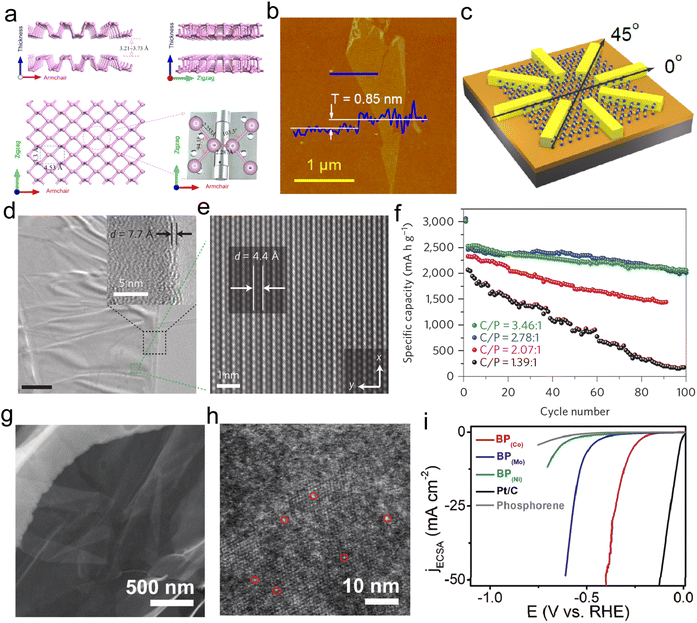 | ||
| Fig. 2 Characterization and application of BP. (a) The crystal structure of the phosphorene. Reproduced with permission from ref. 39. Copyright 2015, American Chemical Society. (b) Atomic force microscopy image of the single-layer phosphorene with the thickness of 0.85 nm. (c) The corresponding device structure of the angle-dependent transport property. Reproduced with permission from ref. 45. Copyright 2014, American Chemical Society. (d and e) TEM and AC-TEM images of the phosphorene–graphene sandwich structure. (f) Sodium ion battery performance using the phosphorene–graphene hybrid materials as the anode. Reproduced with permission from ref. 2. Copyright 2015, Springer Nature. (g and h) Enlarged HRTEM images of phosphorene-loaded Co atoms, which are highlighted by red circles. (i) The LSV curves of the Co–P, Mo–P, Ni–P, phosphorene and commercial Pt/C. Reproduced with permission from ref. 50. Copyright 2019, Wiley-VCH. | ||
To enable the application of phosphorene-based materials in the field of energy storage, phosphorene–graphene hybrid material has been fabricated with a sandwich structure in which phosphorene layers are enclosed by graphene layers. The magnified HRTEM images (Fig. 2d and e) clearly show nanobelt-like objects in this multi-level structure with a distance of 0.44 nm between the phosphorene–graphene layers.2 The sandwich structure exhibited an excellent capacity (2440 mA h g−1) under the current density of 0.05 A g−1, together with an 83% capacity retention even after 100 cycles (Fig. 2f). Yasaei et al. successfully prepared single phosphorene through the liquid-phase exfoliation method, using dimethylformamide (DMF) and dimethyl sulfoxide (DMSO) as solvents.46 They found that the aprotic and polar solvents were appropriate candidates for stable dispersion of 2D atomically layered phosphorene. With the development of advanced characterization techniques, spherical aberration-corrected TEM (AC-TEM) was successfully applied to observe the atomic layer stacking of black phosphorus.47–49 Although phosphorene has great potential for energy storage and catalysis, the chemical instability greatly limits its direct practical applications as an electrode or electrocatalyst.21 To improve the electrocatalytic performance and application of phosphorene, Danni Liu et al. synthesized 2D layer phosphorene to load single Co atoms in order to generate single-atom composite catalysts.50 TEM images (Fig. 2g and h) of the obtained single-atom Co–P catalysts show the large-scale membrane-like phosphorene support on which cobalt atoms were randomly dispersed. As expected, the Co–P single atom catalyst presented better HER activity with a potential of 0.294 V at 10 mA cm−2, as illustrated in Fig. 2i.50 Interestingly, the Co doping can enhance the electro-conductivity of the phosphorene, with an increase of Co–P active sites and suitable adsorption energy, resulting in improved electrocatalytic activity and durability.50 In fact, non-metal doping can also effectively enhance the stability of phosphorene. Yang and co-authors used a DFT calculation to study the effect of nonmetallic element dopants on the stability of phosphorene.51 They found the 2nd period and VIA group atoms (X)-doped phosphorene can provide superior internal stability through the formation of X–P bonding. The charge transfer between P and heteroatoms is mainly determined by the local charge and global Fermi level of X-doped phosphorene.51 Notably, the local charge of P sites plays a decisive role for the X species with dramatic charge transfer.
Additionally, multifunctional modification of phosphorene could effectively enhance its structural stability for application. Phosphorene nanosheets were incorporated into porous carbon nanofiber as an electrode for Li–S batteries, which showed improved cycling performance with a capacity retention rate above 660 mA h g−1 after 500 cycles, and only 0.053% capacity decay per cycle.52 The superior electrochemical stability of the phosphorene-based composite revealed an effective strategy to enhance the stability through the incorporation of carbon fiber. Moreover, phosphorene-based hybrid materials or heterostructures deserve further exploration for these applications. In fact, the superb flexibility of phosphorene makes it also viable for various types of flexible and wearable electronic devices.
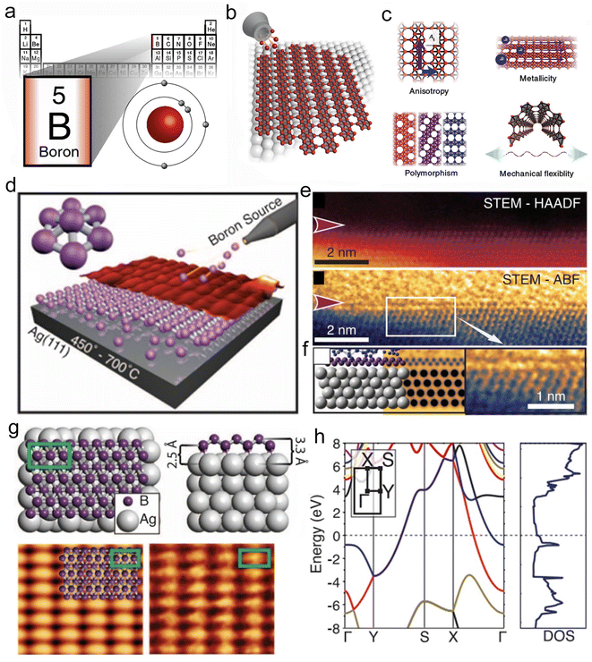 | ||
| Fig. 3 Preparation and structural characterization of borophene. (a) Location of boron element in the periodic table. (b) Generation of borophene on the metal substrate. (c) Structure and properties of the borophene. Reproduced with permission from ref. 53. Copyright 2018, Springer Nature. (d) Growth of borophene sheets on the Ag (111) substrate by distorting the B7 cluster. (e) Cross-sectional AC-STEM and ABF images of the borophene. (f) The model structure of the Si-capped borophene, the corresponding simulated ABF image, and enlarged ABF image from the (e). (g) Atomic model of the borophene structure and the simulated STM image. (h) Band structure of the borophene. Reproduced with permission from ref. 55. Copyright 2015, AAAS. | ||
The electronic band structure of 2D borophene exhibits metallic conduction as the bands cross the Fermi level along the G–X and Y–S directions (Fig. 3h).55 Moreover, the electrical conductivity of 2D borophene is confined along the chains.51 Due to its specific anisotropic metal structure, borophene has been proved to be an efficient energy storage material, such as anode material for rechargeable metal-ion batteries.56,57 The ultrahigh ions diffusion coefficient and energy storage capacity of borophene made it a promising candidate for energy storage, but its practical application was greatly limited due to its high cost. Therefore, developing a low-cost method for large-scale preparation of free-standing borophene would be significant for its future development in energy storage or catalysis.
It is worth noting that the strong reaction between the silicon and the substrate drives the hybridized metallic states of monolayer silicene; thus, it is difficult to obtain free-standing monolayer silicene.59 The phase transfer process would be helpful for the preparation of single-layer silicene. Fig. 4a displays the typical synthesis–transfer–fabrication process of a silicene device which includes four steps: (1) generation of silicene on Ag (111) thin film, (2) in situ Al2O3 capping, (3) encapsulated delamination transfer of silicene layer and (4) formation of back-gated silicene transistors.60 The Scanning Tunneling Microscope (STM) image in Fig. 4b shows the Si overlayers with the unique six-membered ring structure.60 Although the obtained silicene had high quality, its large-scale production faced great difficulties. Liu et al. prepared high-quality silicene through the liquid oxidation and exfoliation of CaSi2 as shown in Fig. 4c.61 HRTEM imaging depicted the 2D morphology of the silicene, and characterization by AFM indicated that the thickness of the obtained silicene was 0.6 nm (Fig. 4d and e).61 Compared with bulk silicon, silicene has a larger specific surface area and a thinner thickness, which is more conducive to the transport of surface charges. Few-layer silicene nanosheets were used as anodes for lithium-ion batteries, which exhibited a high capacity of 721 mA h g−1 at 0.1 A g−1 with excellent cycling stability (Fig. 4f).61 The unique 2D structure of silicene endows it with the specific property of avoiding huge volume expansion during cycling, thereby maintaining this extraordinary cycling stability. Although there has been some progress in the study of silicene since 2007, more innovative designs combining theoretical analysis and experimental verification need to be further explored.62
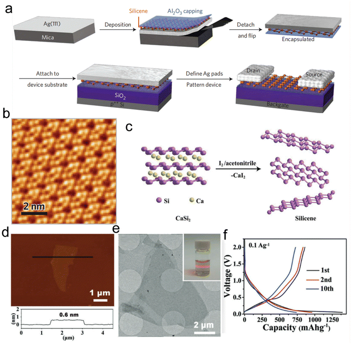 | ||
| Fig. 4 Preparation of silicene. (a) The synthesis–transfer–fabrication process of silicene. (b) STM image of the obtained silicene. Reproduced with permission from ref. 60. Copyright 2015, Springer Nature. (c) Schematic illustration of the preparation process of silicene based on the liquid oxidation and exfoliation route. (d) AFM image of silicene revealing a thickness of 0.6 nm. (e) TEM image of the silicene. (f) The 1st, 2nd, and 10th charge–discharge profiles of the silicene anode for lithium-ion battery application. Reproduced with permission from ref. 61. Copyright 2018, Wiley-VCH. | ||
2.2 2D metal nanomaterials
2D metals have received an enormous amount of research effort thanks to their special catalytic, optical, and electronic properties compared with their bulk structure.63,64 The nanostructures of 2D metals can be directly observed following the development of electron microscopy techniques. Given that the 2D structure offers a larger specific surface area than the 3D bulk structure, it can fully expose the under-coordinated atoms, resulting in excellent catalytic performance. Synthesizing ultra-thin, large-scale 2D metal materials has great significance for the widespread use of 2D metal nanosheets for energy storage and catalysis.The most common 2D metals include Au, Ag, Pt, Pd, Sb and Bi, among others. The capping agent strategy has been widely adopted to design and synthesize 2D metallic materials.63,64 Li et al. elaborated a method to synthesize large, single-crystal Au nanosheets through a polyol process (Fig. 5a and b).65 Carbon monoxide (CO) was used as a capping agent to obtain materials with unusual morphologies. The average thickness of the obtained Au nanosheets was approximately ∼9 nm and the size was in the microscale (Fig. 5c).65 Zheng and co-workers reported a facile route to prepare ultrathin hexagonal Pd nanosheets with CO.66 The as-prepared Pd nanosheets showed 2.5 times higher performance than commercial Pd black in formic acid oxidation.66 Using a similar approach, they also synthesized atomically thick Rh nanosheets (Fig. 5d and e) in a glass vessel in the presence of PVP, N,N-dimethylformamide (DMF) and CO gas.67 The prepared Rh nanosheets had a rhombus shape with a size of about 1 μm. The SAED and HRTEM images in Fig. 5f–h indicated that the Rh nanosheets had mainly exposed (422) facets with a lattice spacing of 0.233 nm.67 HRTEM images from the cross-section showed that the thickness of a single Rh nanosheet was approximately 1 nm, which corresponds to about five atomic layers. Matsumoto and co-workers obtained monolayer Pt nanosheets by electrochemical reduction and porous 2D nanosheets by chemical reduction (Fig. 5i and j).19 The monolayer Pt nanosheets exhibited a ∼1 nm thickness as characterized by AFM. Moreover, these materials demonstrated a better oxygen reduction reaction (ORR) activity than Pt/C. Extensive studies have shown that producing catalysts by alloying different metals could effectively enhance their catalytic activity. To further facilitate the generation of surface-bound OH (OHads) species, alloying Pd and Pt with other transition metals such as Ag and Ni can effectively improve the activity for the oxidation of alcohols.68,69 Han et al. synthesized Pd–Pt–Ag trimetallic nanosheets, as illustrated by TEM and the corresponding EDS images in Fig. 5k, l and m. This composite showed superior performance for ethanol oxidation reaction (EOR) than Pd/C and Pt/C (Fig. 5n).70
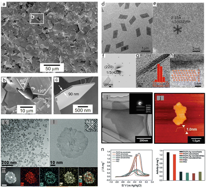 | ||
| Fig. 5 Common 2D metals. (a) Low-magnification FESEM images of Au nanosheets. (b) Locally enlarged image of the frame in (a). (c) The thickness of a single Au nanosheet. Reproduced with permission from ref. 65. Copyright 2006, Wiley-VCH. (d and e) Enlarged TEM images of Rh nanosheets with a long edge length of 880 nm. (f) SAED patterns of a single Rh nanosheet (shown in the inset). (g and h) TEM images from the cross-section. Reproduced with permission from ref. 67. Copyright 2015, Wiley-VCH. (i) TEM image of DS-nanosheets after electrochemical reduction. (j) AFM image of DS-nanosheets after electrochemical reduction. Reproduced with permission from ref. 19. Copyright 2014, The Royal Society of Chemistry. (k) Low- and (l) high-magnification TEM images of Pd–Pt–Ag nanosheets (the inset shows the visible lattice fringes). (m) HAADF-STEM image and corresponding EDS elemental maps of a Pd–Pt–Ag nanosheet. Scale bar: 20 nm. (n) Electrochemical performance of the Pd–Pt–Ag nanosheets. Reproduced with permission from ref. 70. Copyright 2016, Wiley-VCH. | ||
As another important kind of catalyst, Ru is broadly used in organic electrocatalysis and small-molecule electrooxidation, such as CO oxidation and OER.71 Peng and co-workers synthesized ultrathin Ru nanosheets with clean surfaces by a facile solvothermal approach.71 The obtained Ru nanomaterials possessed a nanoflower-like morphology that assembled from flakes with a thickness between 1.2 and 2.2 nm. The 2D Ru nanocatalysts exhibited excellent HER properties with a small overpotential of 20 mV under a current density of 10 mA mg−1, which is close to commercial Pt/C powder.71
Besides the more common metals, transition metals such as Ge, Sb and Bi have also been studied for energy storage applications. Serino et al. prepared 2D Ge nanosheets with a method based on the exfoliation of layered GeH crystal.72 The ultrasonication method was applied to exfoliate GeH so as to generate solution-stabilized 2D Ge with a pale red color. Fig. 6a shows the atomic model of the stacked GeH structure. The interlayer spacing of the layered GeH materials was approximately ∼5 nm. Generally, the exfoliated Ge nanosheets would aggregate easily due to the interlayer forces. A polydispersion approach was found to result in Ge nanosheets with good dispersion of isolated single sheets or multilayered stacks. The size of these nanosheets ranged from ∼40 to 200 nm in the lateral direction, as shown in TEM images (Fig. 6b). In addition, the obtained 2D Ge nanosheets presented a superior performance for lithium-ion batteries.72 The constant-current measurement and coulombic efficiency (Fig. 6c) revealed a maximum capacity of 1108 mA h g−1 for the 2D GeH materials. In addition, Zhou and co-workers used few-layer Bi sheets as the anode material for advanced rechargeable batteries.73 The structure and composition of the initial few-layer Bi gradually evolved to NaBi and Na3Bi, as illustrated in Fig. 6d.73 TEM imaging (Fig. 6e) revealed a flower-like morphology for the Bi-material, containing ultra-thin layers. AFM height profile results in Fig. 6f indicated that the Bi nanosheets had an average thickness of ∼4 nm.73 The peaks in the XRD pattern correspond to the (003) and (110) facets of pristine Bi which are shifted to lower angles during the sodiation process (Fig. 6g). The interlayer spacing of Bi layers gradually increases with the intercalation of Na ions. Theoretical simulations predicted that the thin-layered 2D Bi nanomaterials could be used for high-efficiency lithium-ion battery electrodes. Moreover, Sb layers also proved to be an effective candidate for the Li-ion battery application. The electron localization function (ELF) images in Fig. 6h helped in the investigation of the existing position of Li atoms and the electron distribution of the 2D Sb layer with 32 Li atoms adsorbed, illustrating an increase in electron gas distribution and capability for the battery.74
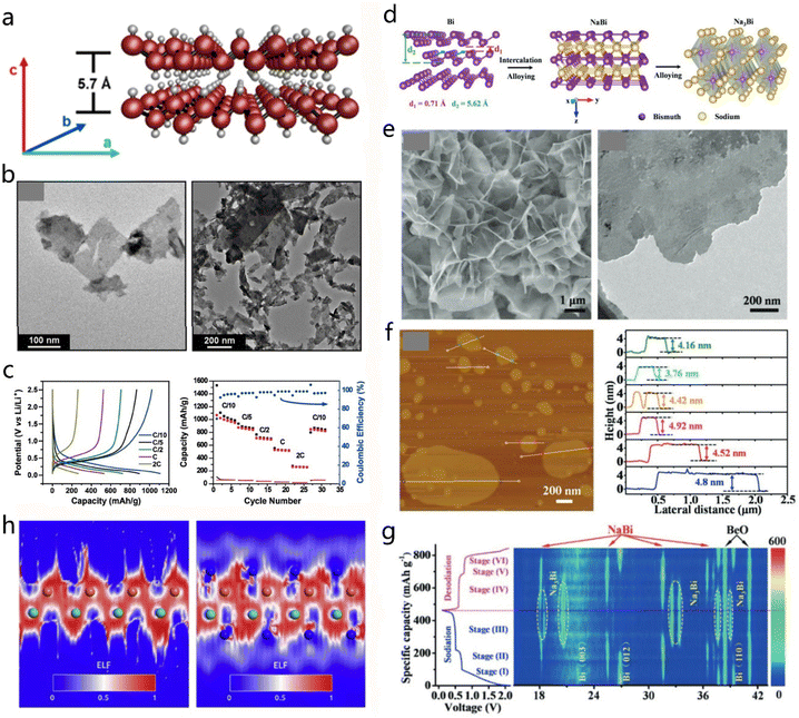 | ||
| Fig. 6 Uncommon 2D metals. (a and b) Crystal model and TEM images of 2D Ge nanosheets. (c) Lithium battery performance of the 2D Ge nanosheets. Reproduced with permission from ref. 72. Copyright 2017, American Chemical Society. (d) The preparation process of the 2D Na3Bi nanosheets evolved from Bi bulk material and NaBi during the electrochemical sodiation. (e and f) TEM and AFM images of 2D Na3Bi, together with the corresponding height profile. (g) In situ XRD results of Bi anode under different states, and the relationship between voltage and charge/discharge capacities. Reproduced with permission from ref. 73. Copyright 2019, Wiley-VCH. (h) The electron localization function (ELF) from (011) section of 2D Sb and LiSb with 32 Li atoms adsorbed. Reproduced with permission from ref. 74. Copyright 2017, Elsevier. | ||
When 2D metal materials are thin enough, the structure could appear to have a graphene-like morphology, which is called metallene. Luo and co-workers developed an efficient solution-mediated method for the synthesis of ultrathin Pd and Pd-based alloy catalysts.75 As shown in Fig. 7a and b, representative HRTEM and STEM images demonstrate the lamellar wrinkle structure of the PdMo bimetallene. It has to be highlighted that this approach successfully produced free-standing PdMo bimetallene with a thickness as small as 0.88 nm, as studied by high-resolution AFM (Fig. 7c and d). To evaluate the electrocatalytic property of the prepared metallene, the free-standing PdMo catalyst was studied in comparison with commercial Pd/C and Pt/C for the ORR process. The ORR polarization curves in Fig. 7e reflected the superior ORR activity of PdMo metallene with a half-wave potential of 0.95 V, which was better than Pt/C (0.85 V) and Pd/C (0.84 V). PdMo bimetallene had a mass activity of 16.37 A g−1Pt at 0.9 V, which was 327.4 and 77.9 times higher than that of Pd/C and Pt/C, respectively, demonstrating its bright potential for future catalytic applications.75
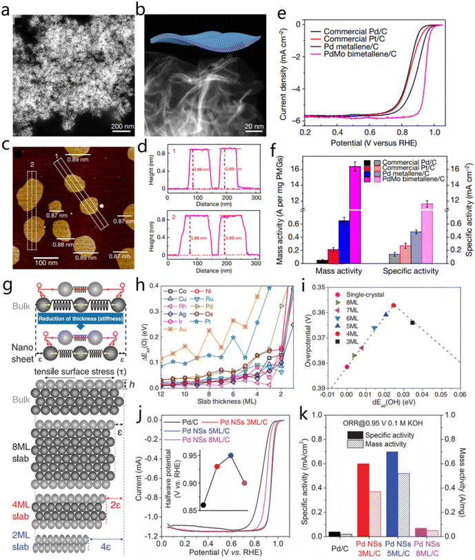 | ||
| Fig. 7 2D Pd-based nanosheets and their electrocatalytic properties. (a and b) Magnified HAADF-STEM images of PdMo bimetallene. (c and d) AFM image and the corresponding line scan curves of the PdMo bimetallene. (e and f) LSV curves of ORR and the mass and specific activities of PdMo bimetallene, Pd metallene, commercial Pt/C, and Pd/C. Reproduced with permission from ref. 75. Copyright 2019, Nature Publishing Group. (g) Schematic illustration to describe the strain of metallenes with the thinning of nanosheets. (h) Effect of metallene thickness with different elemental compositions on OH* binding energy. (i) Volcano plot of the correlation between the OH* binding energy on different thicknesses of metallene and the corresponding ORR activity. (j) The ORR polarization curves of Pd/C, Pd NSs 3ML/C, Pd NSs 5ML/C, and Pd NSs 8ML/C. (k) The mass and specific activities of the four Pd-based catalysts. Reproduced with permission from ref. 76. Copyright 2019, AAAS. | ||
Wang et al. designed a strategy to adjust the intrinsic strain in 2D Pd metallene by changing the thickness of metallene.76 Three-atom-thick metal layer (3 ML), 5 ML and 8 ML Pd nanosheets were prepared to verify the effect of strain regulation on catalytic activity. As the metal layer is gradually reduced, the surface atoms are subjected to the tensile surface stress caused by the inner atoms, as illustrated in Fig. 7g.76 The simulation results illustrated that the binding energy between the active sites and OH intermediates would gradually increase with the decrease of atomic layer, especially when there were only two atomic layers, and the binding energy would dramatically change. The theoretical prediction of O* binding on the surface of the Pd (110) plane claimed the thinner the Pd nanosheets, the larger the binding energy of O* intermediates and the better the ORR activity (Fig. 7h and i).76 The thicknesses of ∼4 ML Pd nanosheets had a direct effect on the increase of reactivity. As expected, Pd NSs (5 ML) exhibited the best ORR activity with the half-wave potential of 0.95 V, which is better than that of PdNSs-8 ML (0.9 V), PdNSs-3 ML (0.93 V), and commercial Pd/C (0.86 V). The PdNSs-5 ML achieved a specific activity of 0.70 mA cm−2 at 0.95 V, which is almost 18 times higher compared with that of Pd/C (0.04 mA cm−2 at 0.95 V) (Fig. 7j and k). Therefore, strain control will be an effective method to further enhance the catalytic activity of metallenes.76
3. 2D compound materials
3.1 Transition-metal dichalcogenides (TMDs)
As a large class of two-dimensional materials, TMDs have been attracting extensive research interest for the exploration of their diverse fascinating properties. The chemical formula of TMDs is collectively referred to as MX2, which consists of transition metals and chalcogens.77 2D TMDs materials are gaining significant attention for energy storage and electrocatalytic applications, due to their unique layered units with high surface area and favorable electronic properties.78 More importantly, 2D TMDs can be easily exfoliated into a few layers or monolayer due to the weak interlayer bonding.1 Heteroatoms and other structural species can be easily introduced into the plane and between layers of 2D TMDs to boost their electrochemical performance. The differences in chemical compositions and structural phases can create a diversity of physical and chemical properties, which results in broad applications.79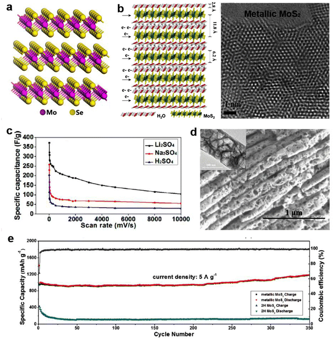 | ||
| Fig. 8 2D MoS2 and its application in energy storage. (a) Schematic of the atomic structural model of MoSe2. (b) Schematic illustration of the multilayer MoS2–H2O based symmetric supercapacitor and atomic resolution TEM image of MoS2 showing atom arrangement. (c) Galvanostatic charge/discharge performance of multilayer metallic MoS2 under different scan rates in three kinds of electrolytes. Reproduced with permission from ref. 6. Copyright 2015, Elsevier. (d) High-magnification SEM image of MoS2 with clear porous structure (inset is the HRTEM image of the as-prepared MoS2 nanotube). (e) Cycling performance of metallic MoS2 nanotube electrode and 2H MoS2 electrode at a current density of 5 A g−1. Reproduced with permission from ref. 85. Copyright 2018, Wiley-VCH. | ||
Bulk binary TMDs are catalytically inert, because the catalytically active sites are mainly concentrated on the edge instead of the basal plane.90,91 In order to promote catalytic activity and electrochemical efficiency, various methods have been employed to maximize the use of edges or to create more edge structures, for example, lithium intercalation and exfoliation.92 Chou et al. found that Li-exfoliated MoS2 preferentially forms relatively stable 1T′ with enhanced electrical conductivity, which possibly improves the catalysis performance.93 With the gradual transformation of the 2H basal plane to 1T′, the hydrogen adsorption free energy (ΔGH) continues to become negative, which is a favorable adsorption condition for HER. As a result, the diminished 1T′ fraction implemented significantly decreases H2 production (Fig. 9a).93 The relationship between ΔGH and the stability of the MoS2 structures was also investigated as a function of H coverage. As shown in Fig. 9b, the 1T′ surface of MoS2 is amenable for catalytic activity, which manifests higher H2 flux than WS2 with a similar phase transformation.93 More interestingly, H coverage is conducive to the stability of the 1T′ phase.93 The stacking arrangements of TMDs notably affect the electrocatalytic effect for HER. Similarly, 3R TaS2 displayed better electrocatalytic performance towards HER than 1T and 2H phase due to the fact that broken inversion symmetry induced greater exposure to edge sites.94 It has to be noted that another factor that affects electrocatalytic performance is cation intercalation. Luxa et al. systematically studied different alkali metals for the exfoliation of MoS2 and WS2 destined for HER.95 They found an important correlation between cation ionic radii and 1T/2H phase ratio.
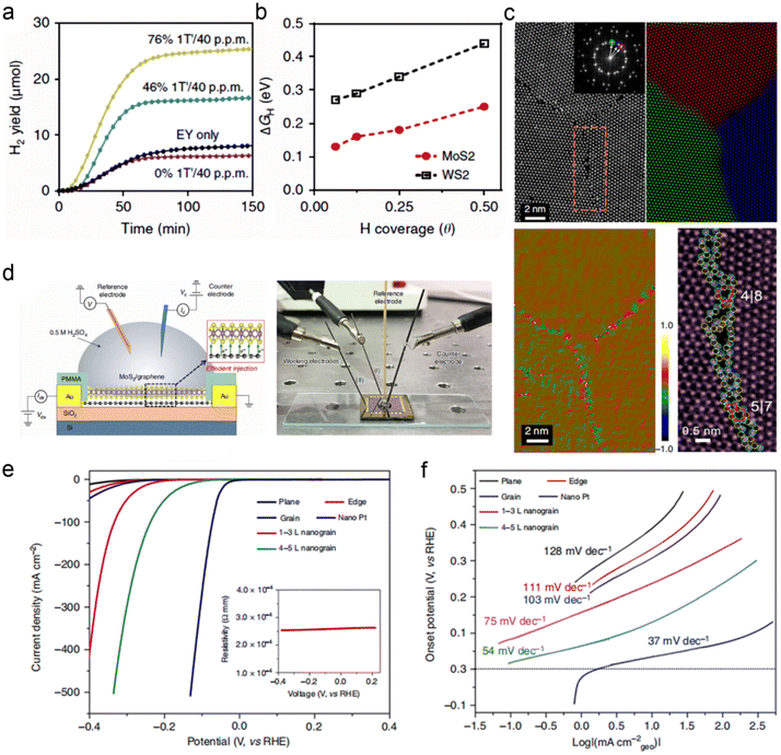 | ||
| Fig. 9 Structure–activity relationship. (a) Cumulative H2 yield with MoS2 undergoing differing degrees of 1T′ transformation. (b) DFT-calculated Gibbs free energy of hydrogen adsorption (ΔGH) as a function of H coverage. Reproduced with permission from ref. 93. Copyright 2015, Nature Publishing Group. (c) STEM image, composite color-coded IFFT, dilatation map, and enlarged STEM images of MoS2 grains. (d) Schematic diagram of the electrolytic cell on the MoS2/graphene and the real photo of the electrolytic cell. (e and f) LSV curves and the corresponding Tafel plots of the catalysts with different grain boundaries. Reproduced with permission from ref. 96. Copyright 2020, Nature Publishing Group. | ||
In addition to intercalation and exfoliation, constructing plenty of grain boundaries in a 2D plane would also boost its catalysis performance. He et al. developed an engineering approach to build grain boundaries in the 2D plane of TMDs films through a Au-quantum-dots-assisted vapor-phase growth.96 The MoS2 film with high-density grain boundaries was successfully prepared and examined by HRTEM and aberration-corrected STEM (Fig. 9c).96 The experimental and simulated results indicated the state of the grain boundaries in the MoS2. To explore the HER performance of the special MoS2, a four-electrode micro-electrochemical cell was adopted to investigate the relevant activity of the nanograin film. Such a cell was built on the surface of the SiO2 layer with Au as the conductive electrode (Fig. 9d).96 After preparing the nanograin-MoS2 film electrode, the electrolyte is directly dropped on the surface of the film electrode to form the in-situ electrolytic cell. This nanograin-MoS2 film device exhibited excellent HER performance with an overpotential of ∼100 mV under the current density of 300 mA cm−2. The results of the HER test in Fig. 9e and f showed that a higher population of grain boundaries in MoS2 was associated with a better HER performance. All these studies showed that TMDs have great potential for electrocatalysis application. However, the limited electrical conductivity, poor cycling stability, difficult monolayer production and uncontrollable exfoliation evolution are still the main drawbacks for TMDs, making their widespread application complex.97,98
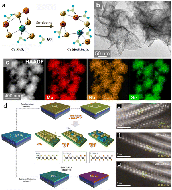 | ||
| Fig. 10 Multielemental 2D TMDs. (a) Optimized molecular structure of pristine and Se-doped Cu2MoS4 and schematic illustration of hydrogen adsorption on the molecule. Reproduced with permission from ref. 102. Copyright 2016, Elsevier. Scheme for the synthesis of the Mo1−xNbxSe2 material by one-pot approach. (b and c) TEM, STEM and the consisted EDS mapping images of Mo1−xNbxSe2. Reproduced with permission from ref. 103. Copyright 2021, American Chemical Society. (d) Preparation schematic of MoSe2 and MoS2(1−x)Se2x ternary alloy. (e–g) Atomic HAADF-STEM images of the MoS2(1−x)Se2x layers obtained under different temperatures. Reproduced with permission from ref. 105. Copyright 2019, Wiley-VCH. | ||
The multicomponent TMD alloy also has great potential for energy storage and conversion applications, as shown in previous reports. Wang et al. confirmed that monolayer SnS2(1−x)Se2x alloy could serve as a potential candidate for LIB anode material based on DFT calculation.104 The monolayer SnS2(1−x)Se2x could effectively enhance the adsorption of Li atoms, and the conductivity would be further increased after lithiation. Additionally, the Se doping could induce lattice expansion and a low diffusion energy barrier.104 Similarly, ternary MoS2(1−x)Se2x alloys were designed by changing the reaction conditions, such as selenization temperature and desulfurization conditions.105 Pure-phase MoS2, MoSe2 and MoS2(1−x)Se2x alloys were prepared through this facile synthetic strategy, as illustrated in Fig. 10d. Under a common desulfurization temperature (600 °C) condition, the MoS2 layer would be generated on the substrate by the decomposition of (NH4)2MoS4, while the MoO3 film would form directly when the desulfurization temperature increased to 800 °C (Fig. 10e). The atomic HAADF-STEM images (Fig. 10e–g) of the MoS2(1−x)Se2x layers obtained under different temperatures further verified that conclusion.105 This ternary MoS2(1−x)Se2x composite material demonstrated excellent optoelectronic properties.
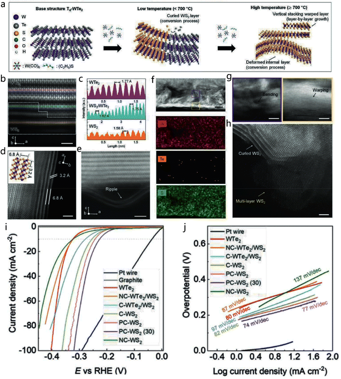 | ||
| Fig. 11 2D TMD heterojunction. (a) Preparation of the WTe2/WS2 heterostructure in the in-plane direction. (b and c) Atomic resolution (AR) STEM image and the consistent EDS line scan of the WTe2/WS2 heterostructure. (d and e) The AR-STEM images in plan-view and cross-sectional of the WTe2/WS2. (f) EDS mapping images of W, Te, and S elements in WTe2/WS2. (g and h) Enlarged AR-STEM images of the selected area in (f). (i and j) HER polarization curves and Tafel plots of the synthesized materials and Pt wire. Reproduced with permission from ref. 107. Copyright 2020, Wiley-VCH. | ||
In recent years, highly nanostructured TMDs hybrids were widely developed to maximize the synergistic coupling effects. Gao et al. reported MoS2/CoSe2 hybrid catalysts with exceptional H2-evolving efficiency, low onset potential and high catalytic current density (Fig. 12a).108 The exceptional HER kinetics of the MoS2/CoSe2 hybrid were reflected based on the low Tafel slope value (∼36 mV per decade), which is close to that of the Pt/C catalyst (30 mV per decade) (Fig. 12b).108 The interfaces between MoS2 and CoSe2 were considered as efficient active sites due to the special valence bond structure. The HER mechanism was proved by establishing an appropriate calculation model, as shown in Fig. 12c.108 The calculated H–H distance in the adsorption, activation and reaction steps, and relatively low Volmer–Tafel reaction activation energy (1.13 eV) contribute to the high catalytic performance of MoS2/CoSe2.108 Yuan et al. reported MoS2-based 2D sandwich-like hybrids, which display excellent ORR activity and supercapacitor performance.109 For these hybrids, functionalized MoS2 acted as templates to conjugate grow microporous polymers with high specific surface area and hierarchical pore distribution. The corresponding 2D porous carbon hybrids after pyrolysis can deliver high capacitance up to 344 F g−1 at 0.2 A g−1 while maintaining a more positive half-wave potential (−0.14 V) and a higher diffusion-limited current (5.4 mA cm−2) in ORR, in comparison with a single component.109 Various novel hybrids, such as MoS2/polyaniline/reduced graphene,11 Ni0.85Se@MoSe2 nanosheet,110 MoS2–Co–C sandwich structures111 and N,S-rGO/WSe2/NiFe-LDH,112 have also been explored as efficient electrode materials or electrocatalysts applied to energy storage and conversion.
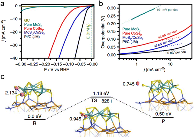 | ||
| Fig. 12 Electrocatalytic hydrogen evolution of different catalysts. (a) Polarization curves for HER on bare GC electrode and modified GC electrodes comprising MoS2/CoSe2 hybrid, pure MoS2, pure CoSe2 and a high-quality commercial Pt/C catalyst. Catalyst loading is about 0.28 mg cm−2 for all samples. Sweep rate: 2 mV s−1. (b) Tafel plot for the various catalysts. (c) HER mechanism. Reaction pathway of HER on MoS2/CoSe2 hybrid according to the Volmer–Tafel route. The calculated distance of two hydrogen atoms and energies are displayed in Å and eV. Blue, orange, azure, yellow and pink indicate Co, Se, Mo, S, and H atoms, respectively. Reproduced with permission from ref. 108. Copyright 2015, Nature Publishing Group. | ||
Many types of inorganic and organic species, for example, carbonaceous materials, metal compounds and polymers, can intercalate 2D TMDs layers to form monolayer or multilayer 2D heterostructures. Surface adsorption/desorption, catalytic reactions and electrochemical kinetics can be effectively boosted after constructing relevant interfacial microstructure.113 Liu et al. reported that a 1T-MoS2/SWNT heterostructure exhibited a low Tafel slope of 36 mV dec−1 with outstanding long-term stability in 0.5 M H2SO4 solution for HER (Fig. 13a and b).114 As shown in Fig. 13c, the improved electrocatalytic activity could be attributed to the strong chemical and electronic coupling effect at the heterogeneous interface, which was caused by electron transfer from the carbon nanotube to the upper surface of 1T-MoS2.114 Apart from effectively preventing the restacking of ultrathin nanosheets, carbonaceous materials can also provide ample interface contact for ion transport.114 It is suggested that heterostructures usually cause the variation of work function and energy band position (such as increasing density of states or reducing work function) of corresponding 2D crystals. Therefore, the heterostructured catalysts allow the easy adsorption of substrate molecules, thereby enhancing the electrocatalytic activity.23 Additionally, TMD heterostructures have also been widely used in batteries and supercapacitors. TiNb2O7@MS HRs hierarchical heterostructures have been prepared which consisted of MoS2 nanosheets as shell and TiNb2O7 nanofiber as core (Fig. 13d).25 This structure displayed high capacities and cycling stability as the anode material of LIBs by providing an entangled structure for Li+ storage and unimpeded conducting pathways for electronic access (Fig. 13e and f).25 Also, MoSe2/Bi2Se3 hexagonal nanosheets heterostructures displayed high specific capacitance (1451.8 F g−1 at 1 A g−1) and satisfactory rate capability with improved supercapacitor performance (Fig. 13g and h),115 which further verified that the heterostructure could effectively promote the electrochemical performance. Related research works on 2D TMDs are ongoing and continue to grow. So far, controllable adjustment of the finite bandgap of 2D TMDs is extremely difficult. The level of quality of 2D TMDs (which has inhomogeneous thickness and contains defects) and the low yield produced by commonly employed methods have hindered widespread applications so far. The hybrid nanostructures-based 2D TMDs are not universal due to their diverse composition, structure and properties.116 The uncontrolled interfacial integration leads to degraded application performance.
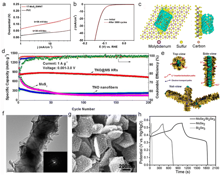 | ||
| Fig. 13 Hierarchical 2D TMDs. (a and b) Tafel plots and stability test of 1T-MoS2/SWNT hybrid and Pt catalyst. Sweep rate: 10 mV s−1 and durability test for the 1T-MoS2/SWNT electrocatalyst with 50 mV s−1 sweep rate. (c) Top (left) and side (right) views of the deformation charge density of interface between 1T-MoS2 fragment and SWNT. The yellow shape represents that the area gains electrons, while the blue shape represents that the area loses electrons, respectively. Reproduced with permission from ref. 114. Copyright 2016, Elsevier. (d) Specific capacity as a function of the cycle number of TNO nanofibers, bare bulk MoS2, and TNO@MS HRs in the voltage range of 0.001–3.0 V at a current density of 1 A g−1. Mesoscopic views of the TNO@MS HRs. The pathways of Li+ ions and electrons are displayed. (e and f) Schematic illustration and TEM image of the TNO@MS HR (the inset presents an electron diffraction pattern of the sample). Reproduced with permission from ref. 25. Copyright 2017, American Chemical Society. (g) SEM image of the MoSe2/Bi2Se3 hybrids and (h) GCD curves of the pure Bi2Se3, pure MoSe2, and MoSe2/Bi2Se3 hybrids at a constant current density of 1 A g−1. Reproduced with permission from ref. 115. Copyright 2017, American Chemical Society. | ||
3.2 Recent development of 2D MXene
As an attractive category of high-profile post-graphene 2D nanomaterials, transition metal carbides and carbonitrides (MXenes) present great application advantages and potential in numerous application fields. MXenes are mainly synthesized by etching and exfoliation from Mn+1AXn phases, where M represents an early transition metal, A is a group 13 or 14 element, X is C and/or N and n = 1, 2, or 3.117–119 There are three different MXene types displayed in Fig. 14a (M2XTx, M3X2Tx and M4X3Tx).119 The excellent properties of 2D MXenes, including adjustable element composition, exposed termination groups, unique metallic nature, and tunable bandgap as well as favorable electronic and mechanical properties, make them outstanding candidates for energy and catalysis domains.119–121 Therefore, several different designs have been developed to optimize the structures and augment the performance of MXene.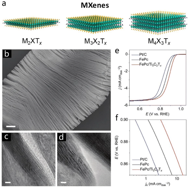 | ||
| Fig. 14 MXenes. (a) Three different MXene types (M2XTx, M3X2Tx, and M4X3Tx). Reproduced with permission from ref. 119. Copyright 2020, American Chemical Society. (b) SEM image of the Ti3C2Tx. (c and d) TEM images of the pristine Ti3C2Tx and Fe Pc/Ti3C2Tx. (e and f) LSV and Tafel plots of the FePc, Fe Pc/Ti3C2Tx, and commercial Pt/C. Reproduced with permission from ref. 123. Copyright 2018, Wiley-VCH. | ||
Insertion of ions or molecules and surface modification are usually introduced into layered MXene to induce a superior electrochemical feature.122 Li and co-workers synthesized 2D Ti3C2Tx and modified it with iron phthalocyanine (FePc) to form the Fe Pc/Ti3C2Tx hybrid.123 The pristine Ti3C2Tx displayed a multilayer stacking morphology as shown in Fig. 14b. After combination with Fe Pc molecular, the surface of Ti3C2Tx was covered by an organic molecular layer which could be effectively identified by TEM characterization (Fig. 14c and d).123 It has to be noted that the Fe Pc/Ti3C2Tx material demonstrated excellent ORR performance with a most positive half-wave potential of ∼0.866 V, which is much better than the pure FePc (0.86 V), and commercial Pt/C (0.84 V), due to the easier electron transfer from the O intermediate to Fe(II) centers (Fig. 14e and f).
Additionally, Ti-based MXenes are also promising for applications in energy storage due to the variable oxidation state of Ti elements. A pseudocapacitance-dominated charge storage mechanism has been proposed for Ti-based MXene electrodes in sulfuric acid, such as Ti3C2Tx (T![[double bond, length as m-dash]](https://www.rsc.org/images/entities/char_e001.gif) O, OH).124 Li et al. demonstrated that 2D Ti3C2Tx MXenes could be effectively applied to lithium-ion capacitors.16 Ti3C2Tx could be prepared by HF etching, K+ intercalation and subsequent removal of terminal groups (Fig. 15a).16 The interlayer spacing of the Ti3C2Tx gradually increased from 9.3 Å to 12.5 Å, as the structure evolved from bulk to layered MXene. SEM and TEM images in Fig. 15b and c show the morphology of the obtained Ti3C2Tx MXene with an expanded lattice spacing. The obtained Ti3C2Tx displayed ultra-high electrical storage activity with a high capacitance of 517 F g−1 at 1 A g−1 (Fig. 15d). The increased interlayer spacing could facilitate the accessibility of electrolyte ions, which would enhance the electrochemical performance, considering also that a large amount of participating Ti atoms was involved in the electrochemical reactions. Besides, the cationic surfactant–Sn4+ (CTAB–Sn4+) complex intercalated into Ti3C2 MXene could act as the pillaring agent, which greatly promoted the capacity and cycling stability of the MXene.36 The CTAB–Sn4+@Ti3C2 hybrid showed good stability with high-capacity retention (506 mA h g−1) after 250 cycles at 1 A g−1 (Fig. 15e). STEM and the corresponding EDS mapping images (Fig. 15f–h) of the CTAB–Sn4+@Ti3C2 hybrid after 100 cycles helped in the study of the robust surface structure, which indicated the intercalation of Sn in the CTAB–Ti3C2 matrix. The lithium-ion capacitor (anode, Ti3C2 MXene; the cathode, activated carbon) delivered a high energy density of 239.50 W h kg−1 at a relatively high power density of 10.8 kW kg−1 (Fig. 15i).36 In fact, surface functional groups and layer stack density can notably affect the volumetric and gravimetric capacitance of MXenes. Oxygen-containing groups-modified MXenes tend to higher capacitance values because these oxygen-containing groups participate in electrochemical reactions. Insertion and functional modification were also effective strategies to tune the stack density of carbide materials, thus affecting the gravimetric capacitance.125
O, OH).124 Li et al. demonstrated that 2D Ti3C2Tx MXenes could be effectively applied to lithium-ion capacitors.16 Ti3C2Tx could be prepared by HF etching, K+ intercalation and subsequent removal of terminal groups (Fig. 15a).16 The interlayer spacing of the Ti3C2Tx gradually increased from 9.3 Å to 12.5 Å, as the structure evolved from bulk to layered MXene. SEM and TEM images in Fig. 15b and c show the morphology of the obtained Ti3C2Tx MXene with an expanded lattice spacing. The obtained Ti3C2Tx displayed ultra-high electrical storage activity with a high capacitance of 517 F g−1 at 1 A g−1 (Fig. 15d). The increased interlayer spacing could facilitate the accessibility of electrolyte ions, which would enhance the electrochemical performance, considering also that a large amount of participating Ti atoms was involved in the electrochemical reactions. Besides, the cationic surfactant–Sn4+ (CTAB–Sn4+) complex intercalated into Ti3C2 MXene could act as the pillaring agent, which greatly promoted the capacity and cycling stability of the MXene.36 The CTAB–Sn4+@Ti3C2 hybrid showed good stability with high-capacity retention (506 mA h g−1) after 250 cycles at 1 A g−1 (Fig. 15e). STEM and the corresponding EDS mapping images (Fig. 15f–h) of the CTAB–Sn4+@Ti3C2 hybrid after 100 cycles helped in the study of the robust surface structure, which indicated the intercalation of Sn in the CTAB–Ti3C2 matrix. The lithium-ion capacitor (anode, Ti3C2 MXene; the cathode, activated carbon) delivered a high energy density of 239.50 W h kg−1 at a relatively high power density of 10.8 kW kg−1 (Fig. 15i).36 In fact, surface functional groups and layer stack density can notably affect the volumetric and gravimetric capacitance of MXenes. Oxygen-containing groups-modified MXenes tend to higher capacitance values because these oxygen-containing groups participate in electrochemical reactions. Insertion and functional modification were also effective strategies to tune the stack density of carbide materials, thus affecting the gravimetric capacitance.125
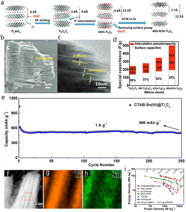 | ||
| Fig. 15 (a) Synthesis of Ti3C2Tx. (b and c) SEM and HRTEM images of Ti3C2Tx. (d) Comparison of capacitance for Ti3C2-based MXene sheets. Reproduced with permission from ref. 16. Copyright 2017, Wiley-VCH. (e) Long cycling performance of CTAB–Sn(IV)@Ti3C2 at a current density of 1 A g−1. (f–h) STEM and EDS mapping images of the CTAB–Sn(IV)@Ti3C2 after 100 cycles test. (i) Ragone plots of CTAB–Sn(IV)@Ti3C2//AC LIC compared with other MXene materials. Reproduced with permission from ref. 36. Copyright 2017, https://pubs.acs.org/doi/10.1021/acsnano.6b07668, and further permission related to the material excerpted should be directed to American Chemical Society. | ||
It was confirmed that the gravimetric capacity of 2D MXene was mainly traced to the ions penetrating between sheets instead of M–X bonds. Therefore, the surface layer plays a critical role in the high gravimetric capacity,117 as well as the surface termination groups and environment.126 Recent research found that surface termination groups can affect MXenes’ electronic conductivity by tuning the Fermi level density of states.127 Besides, the mechanical response could be well tuned to integrate different cation and polymer selections.128 PEDOT:PSS had been intercalated into Mo1.33C MXene for a flexible solid-state supercapacitor, exhibiting ultrahigh volumetric capacitance of 568 F cm−3 and energy density up to 33.2 mW h cm−3.129
The electrochemical performance of single-ingredient MXene is usually limited by the inevitable volume changes and ions’ restricted accessibility during charge and discharge stages.128,130 MXene-based hybrid structures can provide a strategy to improve the electrochemical and mechanical properties. The PPy/l-Ti3C2 freestanding film showed a volumetric capacitance of 406 F cm−3 and negligible capacitance loss after 20![[thin space (1/6-em)]](https://www.rsc.org/images/entities/char_2009.gif) 000 cycles.131 An improved capacity of 295 mA h g−1 was obtained at 2 A g−1 for Sb2O3/Ti3C2Tx hybrid electrode used in sodium-ion batteries (SIBs).131 The Sb2O3 nanoparticles and 2D Ti3C2Tx sheets could prevent serious restacking of MXene sheets, while providing sufficient interlayer spacing for the transport of electrons and Na-ions (Fig. 16a).131 Another kind of MXene-based hybrid, MoS2/Mo2TiC2Tx heterostructures, has been formed with two layers of MoS2 intimately on the surface, and this composite (Fig. 16b) showed improved capacity and cyclability as a lithium-ion battery anode.23 The enhanced performance benefited from the strong charge transfer and adsorption of Li and lithium polysulfide on MoS2/Mo2TiC2O2 heterostructures. As shown in Fig. 16c and d, theoretical calculations predicted that a higher number of electrons would be accumulated on the MoS2/Mo2TiC2O2 interface and a more obvious charge transfer would occur between Li2S and Mo2TiC2O2 than MoS2.23
000 cycles.131 An improved capacity of 295 mA h g−1 was obtained at 2 A g−1 for Sb2O3/Ti3C2Tx hybrid electrode used in sodium-ion batteries (SIBs).131 The Sb2O3 nanoparticles and 2D Ti3C2Tx sheets could prevent serious restacking of MXene sheets, while providing sufficient interlayer spacing for the transport of electrons and Na-ions (Fig. 16a).131 Another kind of MXene-based hybrid, MoS2/Mo2TiC2Tx heterostructures, has been formed with two layers of MoS2 intimately on the surface, and this composite (Fig. 16b) showed improved capacity and cyclability as a lithium-ion battery anode.23 The enhanced performance benefited from the strong charge transfer and adsorption of Li and lithium polysulfide on MoS2/Mo2TiC2O2 heterostructures. As shown in Fig. 16c and d, theoretical calculations predicted that a higher number of electrons would be accumulated on the MoS2/Mo2TiC2O2 interface and a more obvious charge transfer would occur between Li2S and Mo2TiC2O2 than MoS2.23
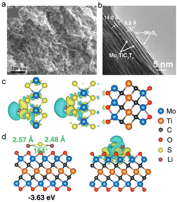 | ||
| Fig. 16 Ti3C2Tx-based MXenes. (a) SEM image of the Sb2O3/Ti3C2Tx sample. Reproduced with permission from ref. 131. Copyright 2017, Springer Nature. (b) Cross-sectional TEM images of MoS2/Mo2TiC2Tx. (c) Differences in charge density for Li on MoS2 and MoS2/Mo2TiC2O2. (d) Differences in charge density of Li2S on MoS2 and Mo2TiC2O2. Turquoise and yellow regions show the depletion and accumulation of electrons, respectively. Reproduced with permission from ref. 23. Copyright 2018, Wiley-VCH. | ||
In addition to LIBs and SIBs, 2D MXene was frequently used in potassium ion batteries (PIBs) and multivalent ion batteries, benefitting from their adjustable interlayer spacing to accommodate large ionic radii of diverse ions. The above-mentioned type of material has been reported to exhibit low diffusion impedance and improved rate capability.132 Ti3C2 MXene prepared from K2Ti4O9 through one-step oxidation and alkalization treatment provided an outstanding reversible capacity of 151 mA h g−1 (50 mA g−1) for PIBs.133 Vahid Mohammadi et al. reported delaminated 2D TBAOH-FL-V2CTx as cathode materials for Al-battery application, which delivered specific capacities of ∼392 mA h g−1 at the current density of 100 mA g−1 (Fig. 17a), and held high-rate capability with expanded interlayer spacing after the intercalation of large organic bases (Fig. 17b).134 The application of 2D MXene in Li–S batteries, such as Ti3C2Tx/RGO,135 CNT-Ti2C, CNT-Ti3C2, CNT-Ti3CN,126,136 Ti2CF2 and Ti2CO2,137 has been recently demonstrated. Dong et al. reported an all-MXene-based Ti3C2 cathode integrated with nanoribbon framework host and nanosheet interlayer structure, which displayed enhanced rate capability and cycling stability in Li–S batteries.137 Owing to the exposed interconnected macropores and degraded shuttle effect of lithium polysulfides, this all-MXene-based Ti3C2 cathode demonstrated such good performance for lithium battery.137
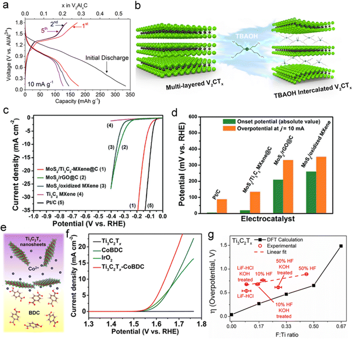 | ||
Fig. 17 Electrochemical performance of the MXene. (a) Charge–discharge curves of TBAOH-FL-V2CTx for the first 5 cycles. (b) Schematic illustration of interlayer expansion of ML-V2CTx MXene through TBAOH intercalation. Reproduced with permission from ref. 134. Copyright 2017, American Chemical Society. (c) Polarization curves of MoS2/Ti3C2-MXene@C, MoS2/oxidized MXene, MoS2/rGO@C, Ti3C2 MXene and Pt/C catalysts at a scan rate of 10 mV s−1 in 0.5 M H2SO4. (d) A comparison of these catalysts in onset potential and overpotential (η) at j = 10 mA cm−2. Reproduced with permission from ref. 10. Copyright 2017, Wiley-VCH. (e, f) Schematic illustration of the preparation of Ti3C2Tx-CoBDC hybrid for OER and OER polarization curves of various electrodes modified by Ti3C2Tx, CoBDC, IrO2, and Ti3C2Tx-CoBDC hybrid in N2-saturated 0.1 M KOH with a scan rate of 1 mV s−1. Reproduced with permission from ref. 141, Copyright 2017, American Chemical Society (g) HER overpotentials of the catalysts at 10 mA cm−2 in 0.5 M H2SO4 electrolyte and the DFT-calculated HER overpotential as a function of F coverage on the basal plane (F![[thin space (1/6-em)]](https://www.rsc.org/images/entities/char_2009.gif) : :![[thin space (1/6-em)]](https://www.rsc.org/images/entities/char_2009.gif) Ti ratio) for Ti3C2Tx. Reproduced with permission from ref. 15. Copyright 2018, American Chemical Society. Ti ratio) for Ti3C2Tx. Reproduced with permission from ref. 15. Copyright 2018, American Chemical Society. | ||
Unlike 2D TMDs (such as MoS2) with semiconducting characteristics and confined active sites at the edge sites, the electrocatalytic activity of 2D MXene was mainly attributed to the excellent charge-transfer capabilities and adequate catalytic sites.37,138–140 Wu et al. proposed a carbon nanoplating principle to assemble MoS2 nanoplates and Ti3C2 MXene, forming a highly active electrocatalyst for HER.10 The MoS2/MXene composite exhibited more positive onset potential and lower overpotential in acidic solution than other MoS2-based HER catalysts, and retained long-term stability (Fig. 17c and d). As shown in Fig. 17e, hydrophilic Ti3C2Tx was used as a conductive carrier to hybridize with highly porous 2D cobalt 1,4-benzenedicarboxylate (CoBDC).141 The obtained Ti3C2Tx-CoBDC complex displayed lower onset potential (1.51 V vs. RHE) and higher current density (1.64 V vs. RHE) for OER, compared with standard IrO2 catalyst (Fig. 17f).141 The functional groups on the surface of MXene could also offer plenty of advantages for electrocatalysis. The structure–activity relationship between HER activity and F coverage was calculated in Fig. 17g. DFT calculations indicated that the ΔGH value would gradually increase as more F atoms were dispersed onto MXene, revealing that the F atoms on the basal plane of MXene could effectively promote the HER performance.15 Functional modification and defect engineering are commonly used methods to improve the catalytic performance of materials. Defect engineering to construct vacancies in 2D MXenes showed unusual superiority in effectively regulating their electrochemical activity.142 Meshkian et al. synthesized 2D W1.33C MXenes with ordered metal divacancies by selectively etching metals in (W2/3M21/3)2AC (M = Al and Sc/Y).143 The prepared W1.33C sheets with ordered divacancies showed excellent HER activity with an overpotential of ∼320 mV at a current density of 10 mA cm−2.143 Therefore, surface oxidation and hydrogenation are critical to improve the catalytic activity of MXenes, due to the change of adsorption free energy on the surface and the surface average valence state.143
3.3 2D layered transition metal hydroxides/oxides
Transition metal oxide (TMO)/hydroxides are two representative types of 2D materials which have received increasing attention in electrocatalysis and energy storage due to their large surface areas, high mechanical stability, and intrinsic redox activity.84,98 Ultrathin or monolayer metal hydroxide nanosheets are usually produced by delamination of their bulk counterparts in suitable organic solvents.144,145 Besides, chemical transformation can also be used to produce ultrathin metal oxides. However, 2D TMO and hydroxides have some disadvantages which hinder their direct application, such as poor conductivity, scant active sites, and inevitable restacking or aggregation during manipulation.146 Therefore, various effective approaches have been reported to tackle the aforementioned limitations. 2D structures of variable-valence metal hydroxides/oxides are widely studied as a primary substrate or basic platform for functional modification to adjust the physicochemical properties for the corresponding application.Many reported 2D TMOs and hydroxide hybrids (e.g., CeO2/MnO2,147 Fe2O3/SnSSe,148 Ni(OH)2/MoO3,149 CoPt@Co(OH)2,150 V2O5@Graphene,151 Co3O4/rGO,152etc.) have displayed excellent electrochemical performance. As shown in Fig. 18a, 2D atomically layered α-Co4Fe(OH)x nanosheet has been synthesized by Jin et al., where the strong electronic interactions between Fe and Co enable improved electrocatalytic activity for OER with an onset potential of 260 mV (Fig. 18b).153 Cai et al. synthesized defect-rich Co3O4 nanosheets using mild ethylene glycol reduction. For this structure, oxygen vacancies and exposed second-layered Co active sites synergistically improved OER catalytic performance.31 Additionally, the advanced architectures could facilitate ion diffusion, while rich active sites could be maintained. 2D holey ZnMn2O4 (ZMO) nanosheets produced by using graphene oxides as a template presented a high capacity of ca.770 mA h g−1 at 200 mA g−1 with ∼56% capacity retention as current density increased to 1200 mA g−1.33 2D mesoporous NiCo2O4 nanosheets have been prepared as a supercapacitor electrode, which displayed slight cathodic peak shift with the scan rate from 5 to 100 mV s−1, indicating fast redox reactions. The good capacitance performance benefited from the constructed mesoporous structure with high surface areas.154
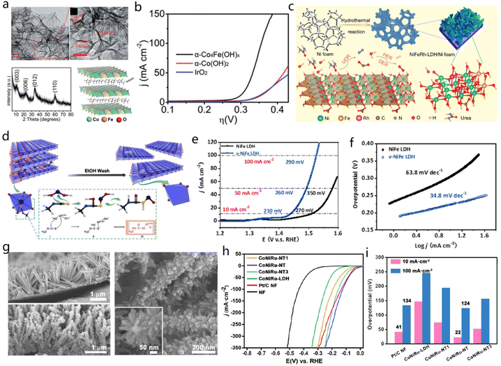 | ||
| Fig. 18 2D LDH. (a) TEM images, XRD, and structural model of α-Co4Fe(OH)x. (b) LSV curves of α-Co4Fe(OH)x, α-Co(OH)2, and IrO2 in 1 M KOH. Reproduced with permission from ref. 153. Copyright 2017, Royal Society of Chemistry. (c) Preparation process of NiFeRh-LDH nanosheets on Ni foam for HER, OER, and UOR applications. Reproduced with permission from ref. 155. Copyright 2021, Elsevier. (d) Synthesis process for targeting specific atoms to NiFe LDH to create vacancies. (e and f) LSV curves and Tafel plots of these catalysts. Reproduced with permission from ref. 156. Copyright 2021, Elsevier. (g) SEM images of the CoNiRu-LDH/NF (top) and CoNiRu-NT (bottom) and an enlarged SEM image of CoNiRu-NT. (h and i) HER performance of the CoNiRu-based catalysts. Reproduced with permission from ref. 157. Copyright 2022, Wiley-VCH. | ||
Sun et al. prepared NiFeRh-LDH on Ni foam by low-temperature hydrothermal reaction. The obtained NiFeRh-LDH contained several elements including Ni, Fe, Rh, C, N, H, and O. Self-supporting structure and polymetallic elements endow the synthesized NiFeRh-LDH with high HER, OER and urea oxidation reaction activity (Fig. 18c).155 To further improve the catalytic activity of the NiFe-LDH materials, a defect strategy was adopted to prepare the NiFe-LDH nanosheets with abundant vacancies. The LDH matrix had an octahedral unit (MO6) with four –OH in a plane and another two –OH at the vertices. Methyl isothiocyanate (CH3N–C–S) functioned as electron acceptor which would be attacked by the –OH, as illustrated in Fig. 18d.156 Meanwhile, the terminal sulfur in –N![[double bond, length as m-dash]](https://www.rsc.org/images/entities/char_e001.gif) C
C![[double bond, length as m-dash]](https://www.rsc.org/images/entities/char_e001.gif) S would bond with the MO6 to form a complex for the generation of NiFe-LDH nanosheets with numerous vacancies. With the formation of defects in NiFe-LDH, the overpotential decreased from 270 mV to 210 mV at 10 mA cm−2 for OER, and also the corresponding Tafel slopes changed from 34.8 to 63.8 mV dec−1 (Fig. 18e and f).156 Ying Wang and co-workers developed a tree-like CoNiRu-NT heterostructured material. The vertically grown CoNiRu-NT featured vertical and slender nanowires on the Ni foam with a ∼100 nm diameter (Fig. 18g).157 After modification with 2,3,6,7,10,11-hexaiminotriphenylene (HITP) molecular, there is a thin MOFs layer coated on the surface of CoNiRu-LDH with nanotrunks surface (CoNiRu-NT). The MOF trunks had a diameter of ∼70 nm. As expected, the CoNiRu-NT demonstrated excellent HER performance (22 mV at 10 mA cm−2), which is better compared with commercial Pt/C (41 mV at 10 mA cm−2), as shown in Fig. 18h and i.157
S would bond with the MO6 to form a complex for the generation of NiFe-LDH nanosheets with numerous vacancies. With the formation of defects in NiFe-LDH, the overpotential decreased from 270 mV to 210 mV at 10 mA cm−2 for OER, and also the corresponding Tafel slopes changed from 34.8 to 63.8 mV dec−1 (Fig. 18e and f).156 Ying Wang and co-workers developed a tree-like CoNiRu-NT heterostructured material. The vertically grown CoNiRu-NT featured vertical and slender nanowires on the Ni foam with a ∼100 nm diameter (Fig. 18g).157 After modification with 2,3,6,7,10,11-hexaiminotriphenylene (HITP) molecular, there is a thin MOFs layer coated on the surface of CoNiRu-LDH with nanotrunks surface (CoNiRu-NT). The MOF trunks had a diameter of ∼70 nm. As expected, the CoNiRu-NT demonstrated excellent HER performance (22 mV at 10 mA cm−2), which is better compared with commercial Pt/C (41 mV at 10 mA cm−2), as shown in Fig. 18h and i.157
3.4 Other 2D compound materials
Considering its large number of unsaturated bonds and a large surface, g-C3N4 constitutes a suitable substrate to coordinate with metal atoms. Various metal catalysts supported on g-C3N4 were fabricated for ORR, OER, HER and energy storage applications.161 In addition, doping elements in g-C3N4 can effectively modify its local electronic structure and improve the activity of the aforementioned material. As shown in Fig. 19a, doping metal atoms in different substitution sites of g-C3N4 provides different charge and spin densities on carbon atoms.162 The g-C3N4-based hybrid can exhibit significant electrochemical performance either as an electrocatalyst or as electrodes. Such hybrid materials include C3N4@MOF,163 g-C3N4 nanosheets/S composites,164 g-C3N4@graphene, Co coordinated g-C3N4/crystalline carbons heterostructure158 and C3N4/Ni2P2O7 nanoarrays.165
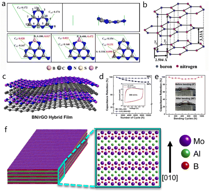 | ||
Fig. 19 2D BN derivatives. (a) Model structures of the pristine g-C3N4 with the top and side view, together with the energetically most favorable structures of B-CN, P-CN and S-CN. Reproduced with permission from ref. 162. Copyright 2017, American Chemical Society. (b) Representative structure of BN. Reproduced with permission from ref. 3. Copyright 2015, Elsevier. (c) Typical structure of BN/rGO hybrid film. Reproduced with permission from ref. 166. Copyright 2016, American Chemical Society. (d) The cyclic performances of NH2-rGO and BN/rGO films after 10![[thin space (1/6-em)]](https://www.rsc.org/images/entities/char_2009.gif) 000 cycles at 300 mV s−1. The inset is the CV curves of BN/rGO film at the first and last cycles. (e) Analysis of the mechanical performance for NH2-rGO and hybrid films. Reproduced with permission from ref. 24. Copyright 2016, American Chemical Society. (f) Crystal model of MoAlB. Reproduced with permission from ref. 167. Copyright 2017, American Chemical Society. 000 cycles at 300 mV s−1. The inset is the CV curves of BN/rGO film at the first and last cycles. (e) Analysis of the mechanical performance for NH2-rGO and hybrid films. Reproduced with permission from ref. 24. Copyright 2016, American Chemical Society. (f) Crystal model of MoAlB. Reproduced with permission from ref. 167. Copyright 2017, American Chemical Society. | ||
4. 2D coordination compounds
2D coordination compounds comprise a class of materials that are composed of organic molecules and/or metal ions, including MOF, COF and polymers. Owing to the porous frameworks/network structures, the coordination compounds showed a very wide application potential in the fields of energy storage, catalysis and electronic device applications.4.1 2D metal–organic frameworks (MOFs)
MOFs, which consist of inorganic metal ions or clusters coordinated with organic linkers, have received continuous attention in the past decades. Ultra-high porosity and tunable functionalities endow them with great advantages for energy storage and conversion.168 To date, 2D MOFs have been primarily used as templates or precursors to design functional hybrid carbon-based structures or various sophisticated nanomaterials.169–172 For example, Lou et al. designed a MOF-derived hollow heterostructure with ZnIn2S4 nanosheets (NSs) grown on the nanocages obtained by the carbonization of ZIF-8@ZIF-67 processers (Fig. 20a).172 Such a heterostructure could expose more active sites and expedite charge separation, thus resulting in enhanced photocatalytic H2 evolution activity. They also confined ultrafine carbide nanocrystals in nitrogen-doped carbon (NC) by annealing ZIF-8 with molybdate.173 Interestingly, the amount of MoO4 units plays a key role in controlling the catalyst phase. Fig. 20b and c suggest that the as-prepared catalyst shows a structure of carbide nanocrystals embedded in NC with uniform morphology and an average size of ∼390 nm. The respective HRTEM image (Fig. 20d) confirms that the two phases of MoC and Mo2C are simultaneously present in the catalyst.173 This specific structure displays superior activity to single-phase for hydrogen evolution.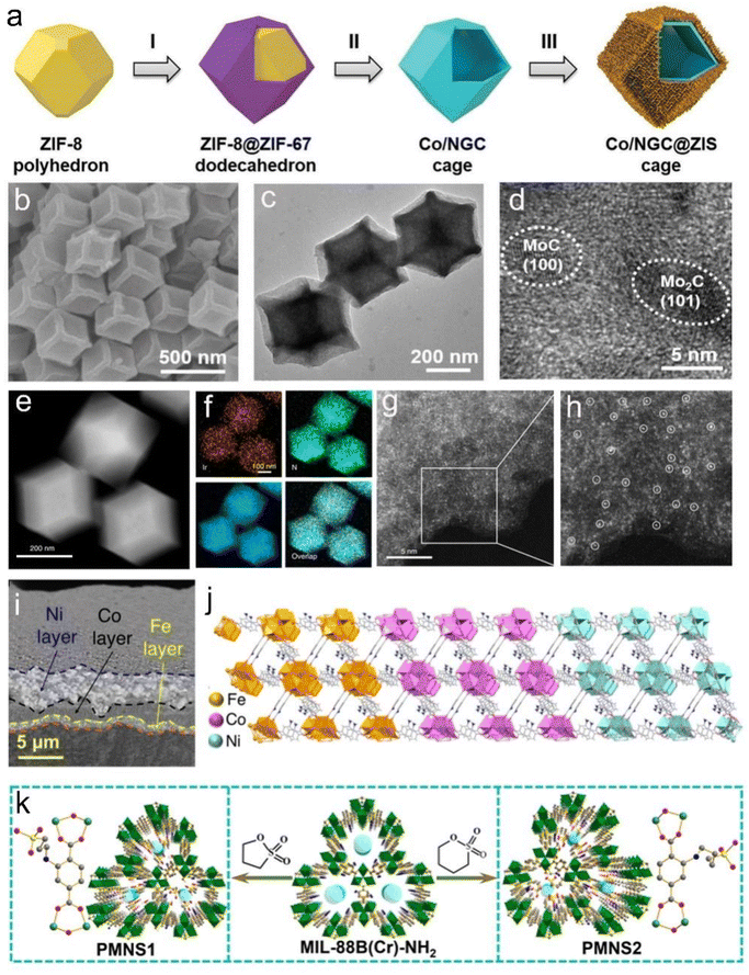 | ||
| Fig. 20 ZIF-driven 2D compounds. (a) Schematic illustration of the hierarchical Co/NGC@ZIS cages. Reproduced with permission from ref. 172. Copyright 2019, Wiley-VCH. (b) FESEM, (c) TEM, and (d) HRTEM images of MoC–Mo2C/PNCDs. Reproduced with permission from ref. 173. Copyright 2019, Wiley-VCH. (e) The HAADF-STEM image of Ir1/CN. (f) EDS elemental mapping of Ir1/CN. (g) The high-resolution HAADF-STEM image of Ir1/CN. (h) Enlarged inset of the image in (g). Reproduced with permission from ref. 174. Copyright 2020, Nature Publishing Group. (i) FE-SEM image of the trilayer Fe–Co–Ni MOF. (j) Schematic illustration of simulated crystal structure model of the trilayer Fe–Co–Ni MOF. Reproduced with permission from ref. 175. Copyright 2022, American Chemical Society. (k) Schematic illustration of the PMNS1 and PMNS2. Reproduced with permission from ref. 176. Copyright 2021, Wiley-VCH. | ||
Li et al. developed a universal host–guest approach to achieve atomic dispersion of various metal atom catalysts.174 Taking MOFs as hosts, the metal precursor guests are trapped to form precursors@MOF composites, leading to an isolated metal single-atom on NC after pyrolysis.174 The related HAADF-STEM image (Fig. 20e) and the corresponding EDS mapping (Fig. 20f) reveal that Ir, C, and N are uniformly distributed throughout the whole Ir1/CN volume. MOF-derived porous Ir1/CN hybrid material can provide a 3D accessible structure for the metal active sites for the catalysis. As expected, the Ir1/CN exhibits excellent electrocatalytic activity toward formic acid oxidation, which is 16 and 19 times higher than the benchmark Pd/C and Pt/C, respectively, while it is much better than Ir/C.174 Mousavi et al. reported trimetallic Fe–Co–Ni MOFs produced by a reductive electrosynthesis strategy; the ligand server served as a bridge to link adjacent metal cations.175 As shown in Fig. 20i, the FE-SEM image indicates that Fe, Co and Ni are present in a layer-by-layer assembled structure, and this distinct crystalline structure is associated with the simulated CPO-10 structure (Fig. 20j).175 The resulting Fe–Co–Ni MOFs show outstanding electrocatalytic activities in promoting water splitting and oxygen reduction. Feng et al. constructed flexible MOFs (FMOFs) aiming to improve proton conductivity via a multivariate synergistic approach for direct methanol fuel cells (DMFCs); Fig. 20k depicts the corresponding synthesis procedure of multivariate FMOFs (labeled PMNS1/2).176 The PMNS1–40 achieved outstanding performance in DMFCs, achieving a superior power density of 34.8 mW cm−2 and long-term stability.176
Simple control of the temperature treatment conditions can lead to a range of porous carbon-based materials. As one of the most commonly used MOF templates, 2D Cu(HBTC)-1 can be simply synthesized through the CuO template and linkers.177,178 Similarly, hollow NiCo2O4 nanowall arrays were achieved using 2D cobalt-based MOFs as a precursor by ion-exchange and annealing treatment (Fig. 21a); the resulting material demonstrated excellent capacitive performance as a supercapacitor.179 Guan et al. assembled a flexible supercapacitor based on Co3O4 cathode and N-doped carbon anode transformed from 2D MOFs, and this material exhibited high specific energy densities (Fig. 21b).180 The porous structure of nanosheets provides efficient contact and diffusion between electrode–electrolyte (Fig. 21c and d). As a template framework, 2D MOFs can be loaded or functionalized with active species and various nanostructures to afford controllable configurations and appealing properties. For example, active molecular catalysts (MS2N2, M = Co and Ni) could be immobilized into 2D MOFs-based carbon electrocatalysts to improve electrical conductivity, catalytic activity and stability for HER. Active centers (MSxNy) shown in Fig. 21e were preferentially protonated, and timely elimination of H2 on the M–N units was ensured.11 Fe-MOF nanoparticles were decorated onto 2D Ni-MOF nanosheet hybrids and the resulting composite demonstrated enhanced catalytic activity toward OER. The restacking of Ni-MOF nanosheets was effectively inhibited after introducing Fe-MOF nanoparticles. Besides, the formed Ni–Fe oxides during OER functioned as real active centers and thus they contributed to high catalytic activity.181 Xu and co-workers used carbonized 2D MOFs as the reactive template to uniformly encapsulate VO2 and Na3V2(PO4)3 (NVP) nanoparticles as Na-ion battery anode and cathodes (Fig. 21f and g); their concept was to manage to deliver high power densities benefiting from high surface areas and conductivity.34 2D MOFs could also operate as versatile supports, which can anchor various precious metal nanoparticles to be potential heterogeneous catalysts (Fig. 21h).178
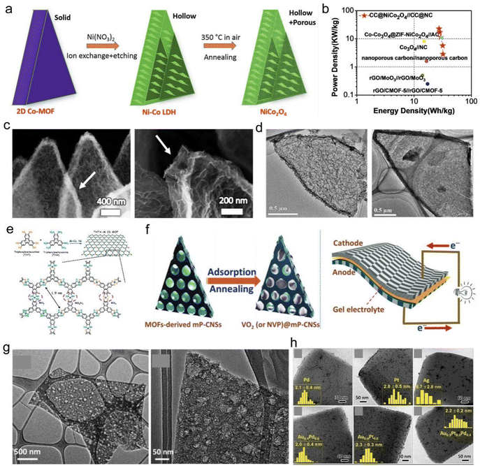 | ||
| Fig. 21 MOF-driven 2D compounds. (a) Preparation of hollow NiCo2O4 nanosheets from 2D Co-MOF. Reproduced with permission from ref. 179. Copyright 2017, Wiley-VCH. (b) Ragone plots of the asymmetric supercapacitor with PVA-KOH gel electrolyte. (c) SEM images of porous Co3O4 nanosheets. (d) TEM images of porous N-doped carbon nanosheets. Reproduced with permission from ref. 180. Copyright 2017, The Royal Society of Chemistry. (e) Structure model of 2D MOF for HER. Reproduced with permission from ref. 11. Copyright 2018, American Chemical Society. (f) Synthesis of VO2@mp-CNSs used as flexible quasi-solid-state sodium-ion capacitor. (g) TEM images of the flexible quasi-solid-state NIC. Reproduced with permission from ref. 34. Copyright 2018, Wiley-VCH. (h) TEM images of Pd/MOFs, Pt/MOFs, Ag/MOFs, Au0.4P 0.6/MOFs, Au0.4Pt0.6/MOFs and Au0.3Pt0.3Pd0.4/MOFs. Reproduced with permission from ref. 178. Copyright 2016, Wiley-VCH. | ||
Another outstanding feature of 2D MOFs is the adjustability of composition and structure according to the requirements of specific applications. Naturally, the microstructures and properties can be effectively modulated by selecting suitable metal ions/clusters coordinated with different organic ligands.182 Small organic coordination ligands can form a high density of frameworks and redox-active sites, which achieve high volumetric and areal capacitance suitable for miniaturized capacitive energy storage.183 Additionally, doping is also a common strategy for 2D MOFs-based nanomaterials, taking into account that it can provide extra active sites and improve electrical conductivity.169
2D MOFs possess a flexible shape and smooth surface which can promote their application in many fields. Meng et al. synthesized single-metal and bimetal MOFs based on Ni and Co ions by controlling the ratios between BDC ligands and Ni or Co ions.184 The obtained CoNi-MOF displays a flexible morphology of 2D nanosheets, as depicted in the SEM images (Fig. 22a).184 AFM imaging of the CoNi-MOF indicated that the nanosheets had a mean thickness of 4.6 nm (Fig. 22b).184 The structural model of the CoNi-MOF in Fig. 22c shows the connection between Ni/Co ions and BDC linkers. To further strengthen the application of MOF in batteries, three different composites, namely S@Ni-MOF, S@Co-MOF and S@CoNi-MOF, were fabricated. S@CoNi-MOF exhibited the best specific capacity among the three materials (Fig. 22e and f).184 To take advantage of the remarkable characteristics of the MOFs, a two-step strategy was developed by Zheng et al. to prepare 2D/1D FeNi LDH/MOF arrays grown on carbon cloth (CC), and the detailed process is shown in Fig. 22g.185 FeNi-LDH nanosheets were synthesized on the CC through a hydrothermal process. SEM and TEM images (Fig. 22h and i) indicated the regular 2D morphology of the FeNi-LDH nanosheets with a smooth surface.185 Although MOFs have wide application, developing new approaches to produce more MOFs also constitutes a challenging goal. Majidi et al. discovered a facile method to synthesize 2D Cu-THQ MOF which could be stably dispersed in (IPA) solution.186 The 2D Cu-THQ MOF showed an average thickness of 10.1 ± 6.7 nm, together with a size of 140 ± 52 nm, based on AFM and dynamic light scattering (DLS) characterizations (Fig. 22k and l). Representative HRTEM images (Fig. 22m and n) showed clearly the elliptical pores in the 2D Cu-THQ MOF, which are smaller than 1 nm with a honeycomb arrangement, corresponding with the AB stacking model (Fig. 22o).186
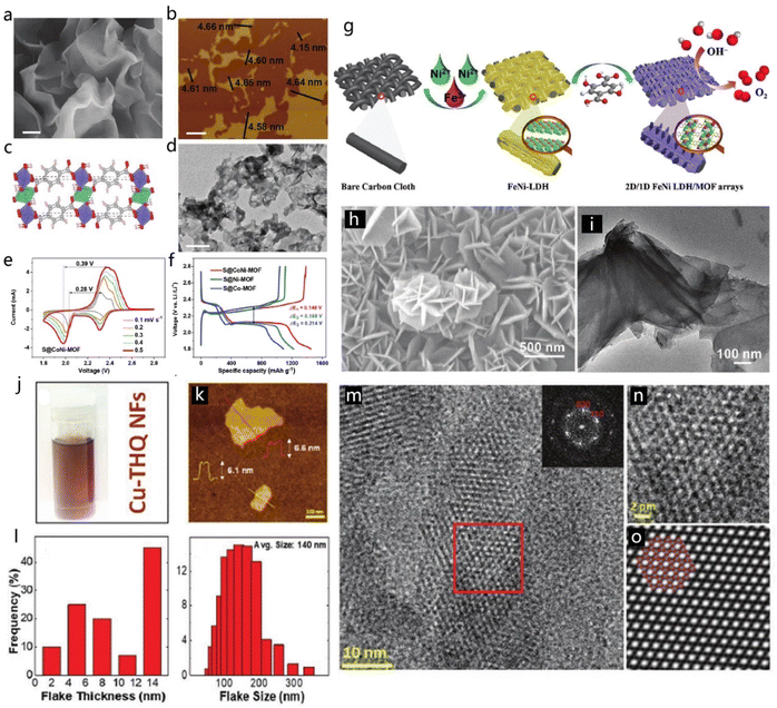 | ||
| Fig. 22 2D MOFs. (a) SEM and (b) AFM images of CoNi-MOF nanosheets. (c) Structural model of the CoNi-MOF. (d) TEM image of the S@CoNi-MOF. (e and f) The electrochemical performance of the S@Ni-MOF, S@Co-MOF and S@CoNi-MOF composites. Reproduced with permission from ref. 184. Copyright 2021, Wiley-VCH. (g) Preparation of 2D/1D FeNi LDH/MOF arrays. (h and i) SEM and TEM images of the FeNi LDH/MOF hybrid. Reproduced with permission from ref. 185. Copyright 2021, Wiley-VCH. (j) Cu-THQ nanosheets dispersed in IPA. (k) AFM image of 2D Cu-THQ. (l) The thickness and size distribution of the 2D Cu-THQ. (m and n) Enlarged HRTEM images of the Cu-THQ and (o) the corresponding AB stacking model. Reproduced with permission from ref. 186. Copyright 2021, Wiley-VCH. | ||
Beside the above-mentioned self-templating strategy, the external-templating approach is also considered as efficacious to prepare multi-morphological nanostructures with optimized performance.175,187 It is well known that good electrical conductivity and high porosity are vital for energy and electrocatalytic applications. However, powder-formed 2D MOFs usually cannot maintain all of their fascinating intrinsic properties at the same time.188,189 Therefore, recent research works have attempted to grow 2D MOF nanostructure arrays on various conductive supports. Such porous 2D structures are very beneficial for energy storage applications. This external-templating strategy can guarantee excellent electrical conductivity and highly porous features with fully exposed active sites without any conductive additives or binders used at the electrodes.
4.2 Covalent organic frameworks (COFs)
Covalent organic frameworks (COFs) are a special type of crystalline polymer with defined organic units connected into periodic skeletons and regular pore structures. The earliest report about COFs can be traced back to 2005, when Côté et al. synthesized highly crystalline and porous COFs by condensation reactions.190 The prominent feature of COFs is that their skeletons and pores can be precisely modulated as a result of the diversity of building blocks and knots. These fascinating features of 2D COFs, such as adjustable redox-active building units, accessible ordered pores and high specific surface area, make them promising materials for energy storage and electrocatalysis-related applications. However, an alarming drawback for 2D COFs has to do with the stacking of the planar sheets due to π–π interactions.21,191 Surface modifications and incorporating additional matrix were widely adopted methods to optimize active sites, and enhance electrical conductivity and structural stability. For example, Yang et al. designed an organic–inorganic heterostructure via the growth of layered COF on Ti3C2 MXene nanosheets (TNS) (Fig. 23a).192 The covalent triazine framework (CTF) has an ordered pore structure while TNS possesses excellent conductivity; therefore, the CTF/TNS specific structure is conducive to ameliorating the performance of lithium–sulfur batteries. Strasser et al. developed a Ni–N–C catalyst derived from the COF (Fig. 23b) for electrochemical CO2 reduction. Interestingly, the Ni–Nx content was affected by the pyrolysis temperature.193 The HAADF-STEM image (Fig. 23c) provides evidence of the presence of isolated Ni single atoms, and the active site density is identified as a critical parameter to describe the catalytic activity. Similarly, Ni-modified 2D COF single-layer sheet displayed highly efficient electrocatalytic performance for HER with Tafel slope of 80.5 mV dec−1 and overpotential of 333 mV at 10 mA cm−2.194 Heteroatom doping, as an effective modification method, could create numerous active sites for electrochemical reaction. Moreover, the synergistic interaction between doped species and COF skeleton could also boost electron transfer.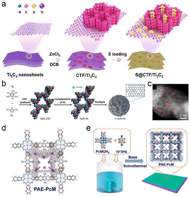 | ||
| Fig. 23 2D COFs. Schematic illustration of the (a) 2D CTF/TNS heterostructures and the S@CTF/TNS composites. Reproduced with permission from ref. 192. Copyright 2020, Elsevier. (b) C-TpDt-Ni MTV-Ti-MOFs/COFs. (c) The high-resolution HAADF-STEM image of C-TpDt-Ni-900. Reproduced with permission from ref. 193. Copyright 2022, Wiley-VCH. Schematic illustration of (d) PAE-PcM (M = Cu, Ni and Co) with weakened in-plane conjugation and ordered out-of-plane stacking, and (e) in situ growth of PAE-PcM films on different substrates by solvothermal reactions. Reproduced with permission from ref. 195. Copyright 2021, American Chemical Society. | ||
Functionalization of organic chains and construction of special structures are versatile measures to optimize electrochemical properties based on 2D COFs. Notably, a well-oriented thin films structure could reduce the adverse effects from grain boundary resistance, thereby facilitating carrier mobilities. Yang et al. reported the preparation of polyarylether-based metallophthalocyanine COFs, which could in situ grow their thin films on diverse substrates (Fig. 23d and e).195 As a proof-of-concept application for all-solid-state supercapacitors, a remarkable capacitance of ∼19 μF cm−2 normalized by surface area and excellent stability of capacitance retention after 1500 cycles were achieved upon using the PAE-PcCo COF electrode material.
The other developed strategies aim to increase active sites and facilitate reactive activity, as shown in Fig. 24.196–201 Mulzer and co-workers incorporated 3,4-ethylenedioxythiophene (EDOT) into the pores of redox-active 2D COF film. The resulting composite films exhibited excellent rate performance (10–1600 C) and stable capacitances continuing for 10![[thin space (1/6-em)]](https://www.rsc.org/images/entities/char_2009.gif) 000 cycles.202 Sulfur was embedded in 2D porphyrin-based COF (Por-COF) as the cathode of Li–S battery, which helped to deliver a stable capacity of 870 mA h g−1 at the current rate of 0.5 C and remaining capacity of 633 mA h g−1 after 200 cycles.203 Metal-free ORR catalyst driving from 2D COF-coated CNT was prepared through thermal polymerization. This novel nanocomposite exhibited high activity toward ORR with 83% initial current density after 36
000 cycles.202 Sulfur was embedded in 2D porphyrin-based COF (Por-COF) as the cathode of Li–S battery, which helped to deliver a stable capacity of 870 mA h g−1 at the current rate of 0.5 C and remaining capacity of 633 mA h g−1 after 200 cycles.203 Metal-free ORR catalyst driving from 2D COF-coated CNT was prepared through thermal polymerization. This novel nanocomposite exhibited high activity toward ORR with 83% initial current density after 36![[thin space (1/6-em)]](https://www.rsc.org/images/entities/char_2009.gif) 000 s test and excellent methanol tolerance.28 Theoretical calculations and experimental results together attributed the enhanced ORR performance to the synergistic effect between heteroatoms.
000 s test and excellent methanol tolerance.28 Theoretical calculations and experimental results together attributed the enhanced ORR performance to the synergistic effect between heteroatoms.
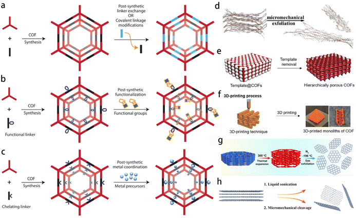 | ||
| Fig. 24 Development strategies to prepare 2D COFs for energy storage and conversion. (a–c) Preparation of functional COFs. Reproduced with permission from ref. 196. Copyright 2021, The Royal Society of Chemistry. (d) Micromechanical exfoliation to obtain few-layered COFs. Reproduced with permission from ref. 197. Copyright 2019, American Chemical Society. (e) Template removal strategy for COFs. Reproduced with permission from ref. 198. Copyright 2019, American Chemical Society. (f) 3D printing process for COFs. Reproduced with permission from ref. 199. Copyright 2019, American Chemical Society. (g) Temperature-swing gas exfoliation of COFs. Reproduced with permission from ref. 200. Copyright 2019, American Chemical Society. (h) Modified 2D COFs. Reproduced with permission from ref. 201. Copyright 2018, Wiley-VCH. | ||
5. Conclusion and outlook
We have attempted to review both preparation process and application of the typical 2D materials for each of the categories. Table 1 briefly summarizes the synthetic approaches of the most representative 2D-based materials and their electrochemical applications.| 2D material | Sample | Synthetic method | Application | Ref. |
|---|---|---|---|---|
| Phosphorene | Phosphorene–graphene hybrid material | Liquid exfoliation | Sodium-ion batteries | 2 |
| Single-atom Co&P | Electrochemical method | Hydrogen evolution reaction | 50 | |
| Borophene | B sheets | Exfoliation | Supercapacitors | 57 |
| Silicene | Few-layer silicene | Liquid oxidation and exfoliation | Lithium-ion batteries | 61 |
| Metal nanomaterials | Pd–Pt–Ag nanosheets | Co-reduction | Ethanol electrooxidation | 70 |
| Ru nanosheets | Solvothermal approach | Hydrogen evolution reaction | 71 | |
| Ge nanosheets | Exfoliation | Lithium-ion batteries | 72 | |
| PdMo bimetallene | Wet-chemical approach | Oxygen reduction reaction | 75 | |
| Pd nanosheets | CO reduction | Oxygen reduction reaction | 76 | |
| Transition-metal dichalcogenides | Metallic MoS2 | Solvothermal method | Lithium-ion batteries | 85 |
| MoS2 | Exfoliation | Hydrogen evolution reaction | 93 | |
| MoS2 nanograin film | Wafer-scale growth | Hydrogen evolution reaction | 96 | |
| MoS2/CoSe2 hybrid | Solvothermal method | Hydrogen evolution reaction | 108 | |
| M-CMP2–800 | Exfoliation and functionalization | Oxygen reduction reaction | 109 | |
| 1T-MoS2/SWNT | Solvothermal method | Hydrogen evolution reaction | 114 | |
| MoS2–MoSe2 | hydrothermal reaction | Li–O2 batteries | 115 | |
| Mo1−xNbxSe2 nanosheets | solvothermal reaction | Hydrogen evolution reaction | 103 | |
| MXene | CTAB–Sn(IV)@Ti3C2 | Liquid-phase prepillaring and pillaring | Lithium-ion capacitors | 36 |
| 400-KOH-Ti3C2 | Cation intercalation and surface modification | Supercapacitors | 16 | |
| Sb2O3/Ti3C2Tx | Etching and hydrolysis | Sodium-ion batteries | 131 | |
| Mo1.33C/PEDOT:PSS | Vacuum filtration and drying | Supercapacitors | 129 | |
| Ti3C2Tx–CoBDC | Etching and exfoliation | Oxygen evolution reaction | 141 | |
| Transition metal oxide (TMO)/hydroxides | α-Co4Fe(OH)x | Coprecipitation method | Oxygen evolution reaction | 153 |
| O-Co3O4 nanosheets | Hydrothermal and annealing | Oxygen evolution reaction | 31 | |
| ZMO nanosheets | Post-thermal treatment | Lithium-ion batteries | 33 | |
| NiCo2O4 nanosheets | Solvothermal reaction | Supercapacitors | 154 | |
| NiFe-LDH/NiFeRh-LDH | Hydrothermal method | Water splitting and urea electrolysis | 155 | |
| v-NiFe LDH | Theoretical calculation | Oxygen evolution reaction | 156 | |
| CoNiRu-NT | Controllable grafted-growth | Water splitting | 157 | |
| Metal–organic frameworks | Co/NGC@ZIS cages | Thermal treatment | Hydrogen evolution reaction | 172 |
| Fe–Co–Ni MOF | Reductive electrosynthesis approach | Oxygen/hydrogen evolution reaction and oxygen evolution reaction | 175 | |
| PMNS1-40 | Chemical grafting | Direct methanol fuel cells | 176 | |
| Hollow NiCo2O4 nanowall | Solution method | Supercapacitor and electrocatalysis | 179 | |
| Covalent organic frameworks | S@CTF/TNS composites | Polymerization and sulfur impregnation | Lithium–sulfur batteries | 192 |
| C-TpDt-Ni | Solvothermal and pyrolysis | Electrochemical CO2 reduction | 193 | |
| PEDOT-modified DAAQ–TFP film | Electropolymerization | Electrical energy storage | 202 | |
| THTNi 2DSP sheets | LB method | Hydrogen evolution reaction | 194 | |
In this review, we have summarized recent developments in various kinds of 2D materials and their derived hybrids. It has focused especially on the relevant properties and applications in electrocatalysis and energy storage of 2D atomic-thin materials, which are emerging alternatives to alleviate the energy and environmental crisis faced by current society. However, it is difficult to effectively screen and prepare the target 2D material with the best performance as there is an extremely large database of 2D material combinations. Fortunately, the rapid development of advanced computational technologies, such as artificial intelligence and cloud/supercomputing, makes it possible to effectively and rapidly screen probable 2D materials for catalysis and energy storage. Specifically, current machine learning (ML) studies have been applied to assist the preparation, structural analysis and property predictions of 2D materials. It is a typical feature to screen 2D materials in large quantities in ML. However, the challenges for ML are still present. The difficulty and high cost of generating data are the biggest challenges for ML, which may cause low fidelity or incomplete predictions. One of the strategies in facilitating ML in the 2D materials field is developing a 2D materials database, including parameters tightly coupled with experimental synthesis. Thus, ML models can be built quickly and efficiently for accurate simulation. Therefore, combining these advanced technologies to design and predict 2D materials in the future will greatly improve efficiency and reduce the cost for functional materials preparation.
Although atomic-level thickness has always been a typical feature of 2D materials, the big challenge is how to maintain this characteristic during the application process, as they stack extremely easily due to the huge specific surface area and abundant dangling bonds at the interface. Stacking and aggregation of 2D materials will quickly reduce the active surface area of 2D materials, thus decreasing the activity. Improving the utilization efficiency of 2D materials by in situ construction of electrodes with vertical growth of nanoarrays on the surface will effectively promote their industrial applications. For 2D TMDs, future efforts should be devoted to developing practical methods for precise control of material properties. There should be better understanding of the performance–property relationships and regular patterns associated with performance to meet practical-level needs. A higher number of new precursors and preparation techniques for MXene should be developed and verified as soon as possible to further explore promising properties and extend the application perspectives. Moreover, the influence of factors associated with energy storage capacities, such as multivalent ions insertion, active terminating group, and hybrids with varied organic or inorganic species, still lack comprehensive experimental research and theoretical calculation. Besides, the degree of understanding of the electrocatalytic properties of MXene is still at a preliminary level. Further research on the identification of the underlying mechanisms which define the performance of highly active MXene catalysts is timely and worthy for the further development of such materials.
There is still great difficulty in the controllable preparation of particular morphologies of MOFs through simple technologies. Adjusting different crystal faces, generating low-dimensional geometric shapes, and maintaining the original advantageous structure are often challenging objectives. More versatile and simple preparation methods with morphology controllability and tunability of properties are desired. Additionally, due to the wide range of metal ions and organic ligands available, new combinations, compositions and topological structures of 2D MOFs are constantly appearing. Accordingly, more sophisticated testing techniques are also needed to better understand the relationship between material structure and properties. Finally, the mechanisms responsible for the improved properties of composite 2D materials need to be unraveled in order to make those materials more applicable for a variety of different fields. Although significant progress has been achieved, the related conclusions, mechanisms, and effects are elusive to date. Fundamental research on certain materials is still in its early stage. It is imperative to synthesize novel materials and further study their structural features and their competitive electrocatalytic properties for more meaningful exploitation at a larger scale.
Conflicts of interest
There are no conflicts to declare.Acknowledgements
This work was supported by the National Natural Science Foundation of China (No. 51902281), Excellent Young Backbone Teacher Project in Xuchang University, the Scientific and Technological Projects of Henan Province (212102210293), and the Young Elite Scientists Sponsorship Program by CAST (2019QNRC001).References
- F. Yi, H. Ren, J. Shan, X. Sun, D. Wei and Z. Liu, Wearable energy sources based on 2D materials, Chem. Soc. Rev., 2018, 47, 3152–3188 RSC.
- J. Sun, H. W. Lee, M. Pasta, H. Yuan, G. Zheng, Y. Sun, Y. Li and Y. Cui, A phosphorene-graphene hybrid material as a high-capacity anode for sodium-ion batteries, Nat. Nanotechnol., 2015, 10, 980–985 CrossRef CAS PubMed.
- A. Gupta, T. Sakthivel and S. Seal, Recent development in 2D materials beyond graphene, Prog. Mater. Sci., 2015, 73, 44–126 CrossRef CAS.
- Y. Zhu, L. Peng, Z. Fang, C. Yan, X. Zhang and G. Yu, Structural engineering of 2D nanomaterials for energy storage and catalysis, Adv. Mater., 2018, 30, 1706347 CrossRef PubMed.
- D. Voiry, H. S. Shin, K. P. Loh and M. Chhowalla, Low-dimensional catalysts for hydrogen evolution and CO2 reduction, Nat. Rev. Chem., 2018, 2, 0105 CrossRef CAS.
- C. Huo, Z. Yan, X. Song and H. Zeng, 2D materials via liquid exfoliation: a review on fabrication and applications, Sci. Bull., 2015, 60, 1994–2008 CrossRef CAS.
- X. Geng, Y. Zhang, Y. Han, J. Li, L. Yang, M. Benamara, L. Chen and H. Zhu, Two-dimensional water-coupled metallic MoS2 with nanochannels for ultrafast supercapacitors, Nano Lett., 2017, 17, 1825–1832 CrossRef CAS PubMed.
- Q. Yun, Q. Lu, X. Zhang, C. Tan and H. Zhang, Three-dimensional architectures constructed from transition-metal dichalcogenide nanomaterials for electrochemical energy storage and conversion, Angew. Chem., Int. Ed., 2018, 57, 626–646 CrossRef CAS PubMed.
- S. S. Chou, N. Sai, P. Lu, E. N. Coker, S. Liu, K. Artyushkova, T. S. Luk, B. Kaehr and C. J. Brinker, Understanding catalysis in a multiphasic two-dimensional transition metal dichalcogenide, Nat. Commun., 2015, 6, 8311 CrossRef CAS PubMed.
- X. Wu, Z. Wang, M. Yu, L. Xiu and J. Qiu, Stabilizing the MXenes by carbon nanoplating for developing hierarchical nanohybrids with efficient lithium storage and hydrogen evolution capability, Adv. Mater., 2017, 29, 1607017 CrossRef PubMed.
- J. Chao, L. Yang, J. Liu, R. Hu and M. Zhu, Oxygen-incorporated and polyaniline-intercalated 1T/2H hybrid MoS2 nanosheets arrayed on reduced graphene oxide for high-performance supercapacitors, J. Phys. Chem. C, 2018, 122, 8128–8136 CrossRef CAS.
- R. Dong, Z. Zheng, D. C. Tranca, J. Zhang, N. Chandrasekhar, S. Liu, X. Zhuang, G. Seifert and X. Feng, Immobilizing molecular metal dithiolene–diamine complexes on 2D metal–organic frameworks for electrocatalytic H2 production, Chem. – Eur. J., 2017, 23, 2255–2260 CrossRef CAS PubMed.
- Q. Fu and X. Bao, Surface chemistry and catalysis confined under two-dimensional materials, Chem. Soc. Rev., 2017, 46, 1842–1874 RSC.
- M. Ghidiu, S. Kota, J. Halim, A. W. Sherwood, N. Nedfors, J. Rosen, V. N. Mochalin and M. W. Barsoum, Alkylammonium cation intercalation into Ti3C2 (MXene): Effects on properties and ion-exchange capacity estimation, Chem. Mater., 2017, 29, 1099–1106 CrossRef CAS.
- A. D. Handoko, K. D. Fredrickson, B. Anasori, K. W. Convey, L. R. Johnson, Y. Gogotsi, A. Vojvodic and Z. W. Seh, Tuning the basal plane functionalization of two-dimensional metal carbides (MXenes) to control hydrogen evolution activity, ACS Appl. Energy Mater., 2018, 1, 173–180 CrossRef CAS.
- J. Li, X. Yuan, C. Lin, Y. Yang, L. Xu, X. Du, J. Xie, J. Lin and J. Sun, Achieving high pseudocapacitance of 2D titanium carbide (MXene) by cation intercalation and surface modification, Adv. Energy Mater., 2017, 7, 1602725 CrossRef.
- C. Feng, Z.-P. Wu, K.-W. Huang, J. Ye and H. Zhang, Surface modification of 2D photocatalysts for solar energy conversion, Adv. Mater., 2022, 2200180 CrossRef CAS PubMed.
- Y. Chen, Z. Fan, Z. Zhang, W. Niu, C. Li, N. Yang, B. Chen and H. Zhang, Two-dimensional metal nanomaterials: Synthesis, properties, and applications, Chem. Rev., 2018, 118, 6409–6455 CrossRef CAS PubMed.
- A. Funatsu, H. Tateishi, K. Hatakeyama, Y. Fukunaga, T. Taniguchi, M. Koinuma, H. Matsuura and Y. Matsumoto, Synthesis of monolayer platinum nanosheets, Chem. Commun., 2014, 50, 8503–8506 RSC.
- J. Liu, Y. Yang, P. Lyu, P. Nachtigall and Y. Xu, Few-jayer silicene nanosheets with superior lithium-storage properties, Adv. Mater., 2018, 30, 1800838 CrossRef PubMed.
- S. Wang, Q. Wang, P. Shao, Y. Han, X. Gao, L. Ma, S. Yuan, X. Ma, J. Zhou, X. Feng and B. Wang, Exfoliation of covalent organic frameworks into few-layer redox-active nanosheets as cathode materials for lithium-ion batteries, J. Am. Chem. Soc., 2017, 139, 4258–4261 CrossRef CAS PubMed.
- J. Zhou, J. Palisaitis, J. Halim, M. Dahlqvist, Q. Tao, I. Persson, L. Hultman, P. O. Å. Persson and J. Rosen, Boridene: Two-dimensional Mo4/3B2-x with ordered metal vacancies obtained by chemical exfoliation, Science, 2021, 373, 801–805 CrossRef CAS PubMed.
- C. Chen, X. Xie, B. Anasori, A. Sarycheva, T. Makaryan, M. Zhao, P. Urbankowski, L. Miao, J. Jiang and Y. Gogotsi, MoS2-on-MXene heterostructures as highly reversible anode materials for lithium-ion batteries, Angew. Chem., Int. Ed., 2018, 57, 1846–1850 CrossRef CAS PubMed.
- C. Chowdhury, S. Karmakar and A. Datta, Capping black phosphorene by h-BN enhances performances in anodes for Li and Na ion batteries, ACS Energy Lett., 2016, 1, 253–259 CrossRef CAS.
- D. Pham-Cong, J. H. Choi, J. Yun, A. S. Bandarenka, J. Kim, P. V. Braun, S. Y. Jeong and C. R. Cho, Synergistically enhanced electrochemical performance of hierarchical MoS2/TiNb2O7 hetero-nanostructures as anode materials for Li-ion batteries, ACS Nano, 2017, 11, 1026–1033 CrossRef CAS PubMed.
- M. Lee, Y. Hwang, K.-H. Yun and Y.-C. Chung, Cathode reaction mechanism on the h-BN/Ni (111) heterostructure for the lithium-oxygen battery, J. Power Sources, 2016, 307, 379–384 CrossRef CAS.
- L. Feng, Y. Liu and J. Zhao, Iron-embedded boron nitride nanosheet as a promising electrocatalyst for the oxygen reduction reaction (ORR): A density functional theory (DFT) study, J. Power Sources, 2015, 287, 431–438 CrossRef CAS.
- Z. Li, W. Zhao, C. Yin, L. Wei, W. Wu, Z. Hu and M. Wu, Synergistic effects between doped nitrogen and phosphorus in metal-free cathode for zinc-air battery from covalent organic frameworks coated CNT, ACS Appl. Mater. Interfaces, 2017, 9, 44519–44528 CrossRef CAS PubMed.
- H. Zhu, X. Gan, A. McCreary, R. Lv, Z. Lin and M. Terrones, Heteroatom doping of two-dimensional materials: From graphene to chalcogenides, Nano Today, 2020, 30, 100829 CrossRef.
- X. Wang, L. Meng, B. Li and Y. Gong, Heteroatoms/molecules to tune the properties of 2D materials, Mater. Today, 2021, 47, 108–130 CrossRef CAS.
- Z. Cai, Y. Bi, E. Hu, W. Liu, N. Dwarica, Y. Tian, X. Li, Y. Kuang, Y. Li, X.-Q. Yang, H. Wang and X. Sun, Single-crystalline ultrathin Co3O4 nanosheets with massive vacancy defects for enhanced electrocatalysis, Adv. Energy Mater., 2018, 8, 1701694 CrossRef.
- T.-X. Huang, B. Dong, S. L. Filbrun, A. A. Okmi, X. Cheng, M. Yang, N. Mansour, S. Lei and N. Fang, Single-molecule photocatalytic dynamics at individual defects in two-dimensional layered materials, Sci. Adv., 2021, 7, eabj4452 CrossRef CAS PubMed.
- L. Peng, P. Xiong, L. Ma, Y. Yuan, Y. Zhu, D. Chen, X. Luo, J. Lu, K. Amine and G. Yu, Holey two-dimensional transition metal oxide nanosheets for efficient energy storage, Nat. Commun., 2017, 8, 15139 CrossRef PubMed.
- D. Xu, D. Chao, H. Wang, Y. Gong, R. Wang, B. He, X. Hu and H. J. Fan, Flexible quasi-solid-state sodium-ion capacitors developed using 2D metal–organic-framework array as reactor, Adv. Energy Mater., 2018, 8, 1702769 CrossRef.
- S. Zhang, Q. Yang, X. Liu, X. Qu, Q. Wei, G. Xie, S. Chen and S. Gao, High-energy metal–organic frameworks (HE-MOFs): Synthesis, structure and energetic performance, Coord. Chem. Rev., 2016, 307, 292–312 CrossRef CAS.
- J. Luo, W. Zhang, H. Yuan, C. Jin, L. Zhang, H. Huang, C. Liang, Y. Xia, J. Zhang, Y. Gan and X. Tao, Pillared structure design of MXene with ultralarge interlayer spacing for high-performance lithium-ion capacitors, ACS Nano, 2017, 11, 2459–2469 CrossRef CAS PubMed.
- N. K. Chaudhari, H. Jin, B. Kim, D. S. Baek, S. H. Joo and K. Lee, MXene: an emerging two-dimensional material for future energy conversion and storage applications, J. Mater. Chem. A, 2017, 5, 24564–24579 RSC.
- Q. Liu, Q. Fang, W. Chu, Y. Wan, X. Li, W. Xu, M. Habib, S. Tao, Y. Zhou, D. Liu, T. Xiang, A. Khalil, X. Wu, M. Chhowalla, P. M. Ajayan and L. Song, Electron-doped 1T-MoS2 via interface engineering for enhanced electrocatalytic hydrogen evolution, Chem. Mater., 2017, 29, 4738–4744 CrossRef CAS.
- L. Kou, C. Chen and S. Smith, Phosphorene: Fabrication, properties, and applications, J. Phys. Chem. Lett., 2015, 6, 2794–2805 CrossRef CAS PubMed.
- A. Carvalho, M. Wang, X. Zhu, A. S. Rodin, H. Su and A. H. C. Neto, Phosphorene: from theory to applications, Nat. Rev. Mater., 2016, 1, 16061 CrossRef CAS.
- X. Guo, W. Zhang, J. Zhang, D. Zhou, X. Tang, X. Xu, B. Li, H. Liu and G. Wang, Boosting sodium storage in two-dimensional phosphorene/Ti3C2Tx MXene nanoarchitectures with stable fluorinated interphase, ACS Nano, 2020, 14, 3651–3659 CrossRef CAS PubMed.
- W. Gao, Y. Zhou, X. Wu, Q. Shen, J. Ye and Z. Zou, State-of-the-art progress in diverse black phosphorus-based structures: basic Properties, synthesis, stability, photo- and electrocatalysis-driven energy conversion, Adv. Funct. Mater., 2021, 31, 2005197 CrossRef CAS.
- M. Zahed, S. Barman, M. Sharifuzzaman, S. Zhang, H. Yoon, C. Park, S. Yoon and J. Park, Polyaziridine-encapsulated phosphorene-incorporated flexible 3D porous graphene for multimodal sensing and energy storage applications, Adv. Funct. Mater., 2021, 31, 2009018 CrossRef CAS.
- H. Huang, Y. Yang, J. Zhu, H.-H. Wu and B. Huang, Rational design of black phosphorene/g-C3B heterostructures as high-performance electrodes for Li and Na-ion batteries, Appl. Surf. Sci., 2021, 561, 150093 CrossRef CAS.
- H. Liu, A. T. Neal, Z. Zhu, Z. Luo, X. Xu, D. D. Tománek and P. D. Ye, Phosphorene: An unexplored 2D semiconductor with a high hole mobility, ACS Nano, 2014, 8, 4033–4041 CrossRef CAS PubMed.
- P. Yasaei, B. Kumar, T. Foroozan, C. Wang, M. Asadi, D. Tuschel, J. E. Indacochea, R. F. Klie and A. Salehi-Khojin, High-quality black phosphorus atomic layers by liquid-phase exfoliation, Adv. Mater., 2015, 27, 1887–1892 CrossRef CAS PubMed.
- A. Nie, Y. Cheng, S. Ning, T. Foroozan, P. Yasaei, W. Li, B. Song, Y. Yuan, L. Chen, A. Salehi-Khojin, F. Mashayek and R. Shahbazian-Yassar, Selective ionic transport pathways in phosphorene, Nano Lett., 2016, 16, 2240–2247 CrossRef CAS PubMed.
- Y. Lee, S. Lee, J. Yoon, J. Cheon, H. Jeong and K. Kim, TEM imaging of edges and point defects in monolayer phosphorene, Microsc. Microanal., 2020, 26, 2348 CrossRef.
- M. Watts, L. Picco, F. Rrussell-Pavier, P. Cullen, T. Miller, S. Bartuś, O. Payton, N. Skipper, V. Tileli and C. Howard, Production of phosphorene nanoribbons, Nature, 2019, 568, 216–220 CrossRef CAS PubMed.
- D. Liu, J. Wang, J. Lu, C. Ma, H. Huang, Z. Wang, L. Wu, Q. Liu, S. Jin, P. K. Chu and X. F. Yu, Direct synthesis of metal-doped phosphorene with enhanced electrocatalytic hydrogen evolution, Small Methods, 2019, 3, 1900083 CrossRef.
- N. Yang, L. Li, J. Li and Z. Wei, Modifying the sensibility of nonmetallic-doped phosphorene by local or global properties, Phys. Chem. Chem. Phys., 2019, 21, 4899–4906 RSC.
- L. Li, L. Chen, S. Mukherjee, J. Gao, H. Sun, Z. Liu, X. Ma, T. Gupta, C. V. Singh, W. Ren, H. M. Cheng and N. Koratkar, Phosphorene as a polysulfide immobilizer and catalyst in high-performance lithium-sulfur batteries, Adv. Mater., 2017, 29, 1602734 CrossRef PubMed.
- A. J. Mannix, Z. Zhang, N. P. Guisinger, B. I. Yakobson and M. C. Hersam, Borophene as a prototype for synthetic 2D materials development, Nat. Nanotechnol., 2018, 13, 444–450 CrossRef CAS PubMed.
- X. Liu, Q. Li, Q. Ruan, M. S. Rahn, B. I. Yakobson and M. C. Hersam, Borophene synthesis beyond the single-atomic-layer limit, Nat. Mater., 2022, 21, 35–40 CrossRef CAS PubMed.
- A. J. Mannix, X.-F. Zhou, B. Kiraly, J. D. Wood, D. Alducin, B. D. Myers, X. Liu, B. L. Fisher, U. Santiago, J. R. Guest, M. J. Yacaman, A. Ponce, A. R. Oganov, M. C. Hersam and N. P. Guisinger, Synthesis of borophenes: Anisotropic, two-dimensional boron polymorphs, Science, 2015, 350, 1513–1516 CrossRef CAS PubMed.
- D. Rao, L. Zhang, Z. Meng, X. Zhang, Y. Wang, G. Qiao, X. Shen, H. Xia, J. Liu and R. Lu, Ultrahigh energy storage and ultrafast ion diffusion in borophene-based anodes for rechargeable metal ion batteries, J. Mater. Chem. A, 2017, 5, 2328–2338 RSC.
- M. Ou, X. Wang, L. Yu, C. Liu, W. Tao, X. Ji and L. Mei, The Emergence and Evolution of Borophene, Adv. Sci., 2021, 8, 2001801 CrossRef CAS PubMed.
- C. J. Rupp, S. Chakraborty, J. Anversa, R. J. Baierle and R. Ahuja, Rationalizing the hydrogen and oxygen evolution reaction activity of two-dimensional hydrogenated silicene and germanene, ACS Appl. Mater. Interfaces, 2016, 8, 1536–1544 CrossRef CAS PubMed.
- J. Zhuang, X. Xu, G. Peleckis, W. Hao, S. X. Dou and Y. Du, A Promising Anode for Lithium-Ion Batteries, Adv. Mater., 2017, 29, 1606716 CrossRef PubMed.
- L. Tao, E. Cinquanta, D. Chiappe, C. Grazianetti, M. Fanciulli, M. Dubey, A. Molle and D. Akinwande, Silicene field-effect transistors operating at room temperature, Nat. Nanotechnol., 2015, 10, 227–231 CrossRef CAS PubMed.
- J. Liu, Y. Yang, P. Lyu, P. Nachtigall and Y. Xu, Few-layer silicene nanosheets with superior lithium-storage properties, Adv. Mater., 2018, 30, 1800838 CrossRef PubMed.
- J. Zhao, H. Liu, Z. Yu, R. Quhe, S. Zhou, Y. Wang, C. C. Liu, H. Zhong, N. Han, J. Lu, Y. Yao and K. Wu, Rise of silicene: A competitive 2D material, Prog. Mater. Sci., 2016, 83, 24–151 CrossRef CAS.
- Y. Song, Y. Yang, C. J. Medforth, E. Pereira, A. K. Singh, H. Xu, Y. Jiang, C. J. Brinker, F. van Swol and J. A. Shelnutt, Controlled synthesis of 2-D and 3-D dendritic platinum nanostructures, J. Am. Chem. Soc., 2004, 126, 635–645 CrossRef CAS PubMed.
- Y. Zuo, L. Wu, K. Cai, T. Li, W. Yin, D. Li, N. Li, J. Liu and H. Han, Platinum dendritic-flowers prepared by tellurium nanowires exhibit high electrocatalytic activity for glycerol oxidation, ACS Appl. Mater. Interfaces, 2015, 7, 17725–17730 CrossRef CAS PubMed.
- C. Li, W. P. Cai, B. Q. Cao, F. Q. Sun, Y. Li, C. X. Kan and L. D. Zhang, Mass synthesis of large, single-crystal Au nanosheets based on a polyol process, Adv. Funct. Mater., 2006, 16, 83–90 CrossRef CAS.
- X. Huang, S. Tang, X. Mu, Y. Dai, G. Chen, Z. Zhou, F. Ruan, Z. Yang and N. Zheng, Freestanding palladium nanosheets with plasmonic and catalytic properties, Nat. Nanotechnol., 2011, 6, 28–32 CrossRef CAS PubMed.
- L. Zhao, C. Xu, H. Su, J. Liang, S. Lin, L. Gu, X. Wang, M. Chen and N. Zheng, Single-crystalline rhodium nanosheets with atomic thickness, Adv. Sci., 2015, 2, 1500100 CrossRef PubMed.
- Y. Zuo, D. Rao, S. Li, T. Li, G. Zhu, S. Chen, L. Song, Y. Chai and H. Han, Atomic vacancies control of Pd-based catalysts for enhanced electrochemical performance, Adv. Mater., 2018, 30, 1704171 CrossRef PubMed.
- Y. Zuo, D. Rao, N. Zhang, T. Li, T. Jing, Š. Kment, Z. Sofer and Y. Chai, Self-reconstruction mediates isolated Pt tailored nanoframes for highly efficient catalysis, J. Mater. Chem. A, 2021, 9, 22501–22508 RSC.
- J. W. Hong, Y. Kim, D. H. Wi, S. Lee, S.-U. Lee, Y. W. Lee, S.-I. Choi and S. W. Han, Ultrathin free-standing ternary-alloy nanosheets, Angew. Chem., Int. Ed., 2016, 55, 2753–2758 CrossRef CAS PubMed.
- X. Kong, K. Xu, C. Zhang, J. Dai, S. N. Oliaee, L. Li, X. Zeng, C. Wu and Z. Peng, Free-standing two-dimensional Ru nanosheets with high activity toward water splitting, ACS Catal., 2016, 6, 1487–1492 CrossRef CAS.
- A. C. Serino, J. S. Ko, M. T. Yeung, J. J. Schwartz, C. B. Kang, S. H. Tolbert, R. B. Kaner, B. S. Dunn and P. S. Weiss, Lithium-ion insertion properties of solution-exfoliated germanane, ACS Nano, 2017, 11, 7995–8001 CrossRef CAS PubMed.
- J. Zhou, J. Chen, M. Chen, J. Wang, X. Liu, B. Wei, Z. Wang, J. Li, L. Gu, Q. Zhang, H. Wang and L. Guo, Few-layer bismuthene with anisotropic expansion for high-areal-capacity sodium-ion batteries, Adv. Mater., 2019, 31, e1807874 CrossRef PubMed.
- A. Sengupta and T. Frauenheim, Lithium and sodium adsorption properties of monolayer antimonene, Mater. Today Energy, 2017, 5, 347–354 CrossRef.
- M. Luo, Z. Zhao, Y. Zhang, Y. Sun, Y. Xing, F. Lv, Y. Yang, X. Zhang, S. Hwang, Y. Qin, J. Ma, F. Lin, D. Su, G. Lu and S. Guo, PdMo bimetallene for oxygen reduction catalysis, Nature, 2019, 574, 81–85 CrossRef CAS PubMed.
- L. Wang, Z. Zeng, W. Gao, T. Maxson, D. Raciti, M. Giroux, X. Pan, C. Wang and J. Greeley, Tunable intrinsic strain in two-dimensional transition metal electrocatalysts, Science, 2019, 363, 870–874 CrossRef CAS PubMed.
- J. Pang, B. Chang, H. Liu and W. Zhou, Potential of MXene-based heterostructures for energy conversion and storage, ACS Energy Lett., 2022, 7, 78–96 CrossRef CAS.
- M. Chhowalla, Z. Liu and H. Zhang, Two-dimensional transition metal dichalcogenide (TMD) nanosheets, Chem. Soc. Rev., 2015, 44, 2584–2586 RSC.
- C. Tan, Z. Lai and Z. J. A. Hua, Ultrathin two-dimensional multinary layered metal chalcogenide nanomaterials, Adv. Mater., 2017, 29, 1701392 CrossRef PubMed.
- B. Zhao, D. Shen, Z. Zhang, P. Lu, M. Hossain, J. Li, B. Li and X. Duan, 2D metallic transition-metal dichalcogenides: Structures, synthesis, properties, and applications, Adv. Funct. Mater., 2021, 31, 2105132 CrossRef CAS.
- W. Choi, N. Choudhary, G. H. Han, J. Park, D. Akinwande and Y. H. Lee, Recent development of two-dimensional transition metal dichalcogenides and their applications, Mater. Today, 2017, 20, 116–130 CrossRef CAS.
- H. Zhang, M. Chhowalla and Z. Liu, 2D nanomaterials: graphene and transition metal dichalcogenides, Chem. Soc. Rev., 2018, 47, 3015–3017 RSC.
- S. Manzeli, D. Ovchinnikov, D. Pasquier, O. V. Yazyev and A. Kis, Nat. Rev. Mater., 2017, 2, 17033 CrossRef CAS.
- B. Mendoza-Sánchez and Y. Gogotsi, 2D transition metal dichalcogenides, Adv. Mater., 2016, 28, 6104–6135 CrossRef PubMed.
- Y. Jiao, A. Mukhopadhyay, Y. Ma, L. Yang, A. M. Hafez and H. Zhu, Ion transport nanotube assembled with vertically aligned metallic MoS2 for high rate lithium-ion batteries, Adv. Energy Mater., 2018, 8, 1702779 CrossRef.
- Y. V. Lim, Y. Wang, D. Kong, L. Guo, J. I. Wong, L. K. Ang and H. Y. Yang, Cubic-shaped WS2 nanopetals on a Prussian blue derived nitrogen-doped carbon nanoporous framework for high performance sodium-ion batteries, J. Mater. Chem. A, 2017, 5, 10406–10415 RSC.
- Z. Li, B. Niu, J. Liu, J. Li and F. Kang, Rechargeable aluminum-ion battery based on MoS2 microsphere cathode, ACS Appl. Mater. Interfaces, 2018, 10, 9451–9459 CrossRef CAS PubMed.
- F. Gao, J. He, H. Wang, J. Lin, R. Chen, K. Yi, F. Huang, Z. Lin and M. Wang, Te-mediated electro-driven oxygen evolution reaction, Nano Res. Energy, 2022, 1 DOI:10.26599/NRE.2022.9120029.
- D. Zhang, G. Zhao, P. Li, Y. Zhang, W. Qiu, J. Shu, Y. Jiang, S. X. Dou and W. Sun, Readily exfoliated TiSe2 nanosheets for high-performance sodium storage, Chem. – Eur. J., 2018, 24, 1193–1197 CrossRef CAS PubMed.
- Q. Liang, Q. Zhang, X. Zhao, M. Liu and A. T. S. Wee, Defect engineering of two-dimensional transition-metal dichalcogenides: Applications, challenges, and opportunities, ACS Nano, 2021, 15, 2165–2181 CrossRef CAS PubMed.
- B. Ni and X. Wang, Face the edges: Catalytic active dites of nanomaterials, Adv. Sci., 2015, 2, 1500085 CrossRef PubMed.
- F. Studt, Catalysis by unusual vacancies, Nat. Catal., 2021, 4, 184–185 CrossRef CAS.
- S. Chou, N. Sai, P. Lu, E. Coker, S. Liu, K. Artyushkova, T. Luk, B. Kaehr and C. Brinker, Understanding catalysis in a multiphasic two-dimensional transition metal dichalcogenide, Nat. Commun., 2015, 6, 8311 CrossRef CAS PubMed.
- Y. Feng, S. Gong, E. Du, X. Chen, R. Qi, K. Yu and Z. Zhu, 3R TaS2 surpasses the corresponding 1T and 2H phases for the hydrogen evolution reaction, J. Phys. Chem. C, 2018, 122, 2382–2390 CrossRef CAS.
- J. Luxa, P. Vosecký, V. Mazánek, D. Sedmidubský, M. Pumera and Z. Sofer, Cation-controlled electrocatalytical activity of Transition-Metal Disulfides, ACS Catal., 2018, 8, 2774–2781 CrossRef CAS.
- Y. He, P. Tang, Z. Hu, Q. He, C. Zhu, L. Wang, Q. Zeng, P. Golani, G. Gao, W. Fu, Z. Huang, C. Gao, J. Xia, X. Wang, X. Wang, C. Zhu, Q. M. Ramasse, A. Zhang, B. An, Y. Zhang, S. Marti-Sanchez, J. R. Morante, L. Wang, B. K. Tay, B. I. Yakobson, A. Trampert, H. Zhang, M. Wu, Q. J. Wang, J. Arbiol and Z. Liu, Engineering grain boundaries at the 2D limit for the hydrogen evolution reaction, Nat. Commun., 2020, 11, 57 CrossRef CAS PubMed.
- N. Choudhary, M. A. Islam, J. H. Kim, T.-J. Ko, A. Schropp, L. Hurtado, D. Weitzman, L. Zhai and Y. Jung, Two-dimensional transition metal dichalcogenide hybrid materials for energy applications, Nano Today, 2018, 19, 16–40 CrossRef CAS.
- K. S. Kumar, N. Choudhary, Y. Jung and J. Thomas, Recent advances in two-dimensional nanomaterials for supercapacitor electrode applications, ACS Energy Lett., 2018, 3, 482–495 CrossRef CAS.
- C. Tan, Z. Lai and H. Zhang, Ultrathin two-dimensional multinary layered metal chalcogenide nanomaterials, Adv. Mater., 2017, 29, 1701392 CrossRef PubMed.
- S. Zhang, Z. Huang, Z. Wen, L. Zhang, J. Jin, R. Shahbazian-Yassar and J. Yang, Local lattice distortion activate metastable metal sulfide as catalyst with stable full discharge–charge capability for Li–O2 batteries, Nano Lett., 2017, 17, 3518–3526 CrossRef CAS PubMed.
- C. Hu, L. Zhang, Z.-J. Zhao, A. Li, X. Chang and J. Gong, Synergism of geometric construction and electronic regulation: 3D Se-(NiCo)Sx/(OH)x nanosheets for highly efficient overall water splitting, Adv. Mater., 2018, 30, 1705538 CrossRef PubMed.
- A. Tiwari, D. Kim, Y. Kim, O. Prakash and H. Lee, Highly active and stable layered ternary transition metal chalcogenide for hydrogen evolution reaction, Nano Energy, 2016, 28, 366–372 CrossRef CAS.
- I. S. Kwon, I. H. Kwak, J. Y. Kim, T. T. Debela, Y. C. Park, J. Park and H. S. Kang, Concurrent vacancy and adatom defects of Mo1−xNbxSe2 alloy nanosheets enhance electrochemical performance of hydrogen evolution reaction, ACS Nano, 2021, 15, 5467–5477 CrossRef CAS PubMed.
- T. Wang, L. Yin, R. Zhao, C. Xia, X. Zhao, Y. An, S. Wei and X. Dai, First-principles study of monolayer SnS2(1−x)Se2x alloys as anode materials for lithium ion batteries, Appl. Surf. Sci., 2018, 457, 256–263 CrossRef CAS.
- Y. R. Lim, J. K. Han, Y. Yoon, J.-B. Lee, C. Jeon, M. Choi, H. Chang, N. Park, J. H. Kim, Z. Lee, W. Song, S. Myung, S. S. Lee, K.-S. An, J.-H. Ahn and J. Lim, Atomic-level customization of 4 in. transition metal dichalcogenide multilayer alloys for industrial applications, Adv. Mater., 2019, 31, 1901405 CrossRef PubMed.
- D. Wang, Z. Zhang, B. Huang, H. Zhang, Z. Huang, M. Liu and X. Duan, Few-layer WS2−WSe2 lateral heterostructures: Influence of the gas precursor selenium/tungsten ratio on the number of layers, ACS Nano, 2022, 16, 1198–1207 CrossRef CAS PubMed.
- Y. Sim, A. Yoon, H. S. Kang, J. Kwak, S. Y. Kim, Y. Jo, D. Choe, W. Na, M. H. Lee, S. D. Park, S. Song, D. Kim, J. W. Yoo, S. Y. Kim, H. Cheong, J. S. Lee, C. H. Lee, Z. Lee and S. Y. Kwon, Design of 2D layered catalyst by coherent heteroepitaxial conversion for robust hydrogen generation, Adv. Funct. Mater., 2020, 31, 2005449 CrossRef.
- M.-R. Gao, J.-X. Liang, Y.-R. Zheng, Y.-F. Xu, J. Jiang, Q. Gao, J. Li and S.-H. Yu, An efficient molybdenum disulfide/cobalt diselenide hybrid catalyst for electrochemical hydrogen generation, Nat. Commun., 2015, 6, 5982 CrossRef CAS PubMed.
- K. Yuan, X. Zhuang, H. Fu, G. Brunklaus, M. Forster, Y. Chen, X. Feng and U. Scherf, Two-dimensional core-shelled porous hybrids as highly efficient catalysts for the oxygen reduction reaction, Angew. Chem., Int. Ed., 2016, 55, 6858–6863 CrossRef CAS PubMed.
- H. Peng, C. Wei, K. Wang, T. Meng, G. Ma, Z. Lei and X. Gong, Ni0.85Se@MoSe2 nanosheet arrays as the electrode for high-performance supercapacitors, ACS Appl. Mater. Interfaces, 2017, 9, 17067–17075 CrossRef CAS PubMed.
- K. Yuan, X. Zhuang, T. Hu, L. Shi, S. Sfaelou, U. Polnick, M. Forster, T. Pichler, T. Riedl, X. Feng, Y. Chen and U. Scherf, 2D heterostructures derived from MoS2-templated, cobalt-containing conjugated microporous polymer sandwiches for the oxygen reduction reaction and electrochemical energy storage, ChemElectroChem, 2017, 4, 709–715 CrossRef CAS.
- X. Xu, H. Chu, Z. Zhang, P. Dong, R. Baines, P. M. Ajayan, J. Shen and M. Ye, Integrated energy aerogel of N,S-rGO/WSe2/NiFe-LDH for both energy conversion and storage, ACS Appl. Mater. Interfaces, 2017, 9, 32756–32766 CrossRef CAS PubMed.
- N. Choudhary, M. AshrafulIslam, J. Kim, T. Ko, A. Schropp, L. Hurtado, D. Weitzman, L. Zhai and Y. Jung, Two-dimensional transition metal dichalcogenide hybrid materials for energy applications, Nano Today, 2018, 19, 16–40 CrossRef CAS.
- Q. Liu, Q. Fang, W. Chu, Y. Wan, X. Li, W. Xu, M. Habib, S. Tao, Y. Zhou, D. Liu, T. Xiang, A. Khalil, X. Wu, M. Chhowalla, P. Ajayan and L. Song, Electron-doped 1T-MoS2 via interface engineering for enhanced electrocatalytic hydrogen evolution, Chem. Mater., 2017, 29, 4738–4744 CrossRef CAS.
- S. Zhang, Z. Huang, Z. Wen, L. Zhang, J. Jin, R. Shahbazian-Yassar and J. Yang, Local lattice distortion activate metastable metal sulfide as catalyst with stable full discharge–charge capability for Li–O2 Batteries, Nano Lett., 2017, 17, 3518–3526 CrossRef CAS PubMed.
- X. C. Lu, Y. Z. Lu, C. Wang and Y. Cao, Efficient photoelectrodes based on two-dimensional transition metal dichalcogenides heterostructures: from design to construction, Rare Mater., 2022, 41, 1142–1159 CrossRef CAS.
- B. Anasori, M. R. Lukatskaya and Y. Gogotsi, 2D metal carbides and nitrides (MXenes) for energy storage, Nat. Rev. Mater., 2017, 2, 16098 CrossRef CAS.
- G. Liang, X. Li, Y. Wang, S. Yang, Z. Huang, Q. Yang, D. Wang, B. Dong, M. Zhu and C. Zhi, Building durable aqueous K-ion capacitors based on MXene family, Nano Res. Energy, 2022, 1 DOI:10.26599/NRE.2022.9120002.
- K. R. G. Lim, A. D. Handoko, S. K. Nemani, B. Wyatt, H.-Y. Jiang, J. Tang, B. Anasori and Z. W. Seh, Rational design of two-dimensional transition metal carbide/nitride (MXene) hybrids and nanocomposites for catalytic energy storage and conversion, ACS Nano, 2020, 14, 10834–10864 CrossRef CAS PubMed.
- H. Wang, Y. Wu, X. Yuan, G. Zeng, J. Zhou, X. Wang and J. W. Chew, Clay-inspired MXene-based electrochemical devices and photo-electrocatalyst: State-of-the-art progresses and challenges, Adv. Mater., 2018, 30, 1704561 CrossRef PubMed.
- J. Zhu, E. Ha, G. Zhao, Y. Zhou, D. Huang, G. Yue, L. Hu, N. Sun, Y. Wang, L. Y. S. Lee, C. Xu, K. Y. Wong, D. Astruc and P. Zhao, Recent advance in MXenes: A promising 2D material for catalysis, sensor and chemical adsorption, Coord. Chem. Rev., 2017, 352, 306–327 CrossRef CAS.
- M. Zhu, Y. Huang, Q. Deng, J. Zhou, Z. Pei, Q. Xue, Y. Huang, Z. Wang, H. Li, Q. Huang and C. Zhi, Highly flexible, freestanding supercapacitor electrode with enhanced performance obtained by hybridizing polypyrrole chains with MXene, Adv. Energy Mater., 2016, 6, 1600969 CrossRef.
- Z. Li, Z. Zhuang, F. Lv, H. Zhu, L. Zhou, M. Luo, J. Zhu, Z. Lang, S. Feng, W. Chen, L. Mai and S. Guo, The marriage of the FeN4 moiety and MXene boosts oxygen reduction catalysis: Fe 3d electron delocalization matters, Adv. Mater., 2018, 30, 1803220 CrossRef PubMed.
- C. Zhan, M. Naguib, M. Lukatskaya, P. R. C. Kent, Y. Gogotsi and D.-e. Jiang, Understanding the MXene pseudocapacitance, J. Phys. Chem. Lett., 2018, 9, 1223–1228 CrossRef CAS PubMed.
- M. Hu, T. Hu, Z. Li, Y. Yang, R. Cheng, J. Yang, C. Cui and X. Wang, Surface functional groups and interlayer water determine the electrochemical capacitance of Ti3C2Tx MXene, ACS Nano, 2018, 12, 3578–3586 CrossRef CAS PubMed.
- X. Liang, Y. Rangom, C. Y. Kwok, Q. Pang and L. F. Nazar, Interwoven MXene nanosheet/carbon-nanotube composites as Li–S cathode hosts, Adv. Mater., 2017, 29, 1603040 CrossRef PubMed.
- J. L. Hart, K. Hantanasirisakul, A. C. Lang, B. Anasori, D. Pinto, Y. Pivak, J. T. Omme, S. J. May, Y. Gogotsi and M. L. Taheri, Control of MXenes’ electronic properties through termination and intercalation, Nat. Commun., 2019, 10, 1–10 CrossRef CAS PubMed.
- Y. Sun, D. Chen and Z. Liang, Two-dimensional MXenes for energy storage and conversion applications, Mater. Today Energy, 2017, 5, 22–36 CrossRef.
- L. Qin, Q. Tao, A. El Ghazaly, J. Fernandez-Rodriguez, P. O. Å. Persson, J. Rosen and F. Zhang, High-performance ultrathin flexible solid-state supercapacitors based on solution processable Mo1.33C MXene and PEDOT:PSS, Adv. Funct. Mater., 2018, 28, 1703808 CrossRef.
- Q. Yang, Z. Xu, B. Fang, T. Huang, S. Cai, H. Chen, Y. Liu, K. Gopalsamy, W. Gao and C. Gao, MXene/graphene hybrid fibers for high performance flexible supercapacitors, J. Mater. Chem. A, 2017, 5, 22113–22119 RSC.
- X. Guo, X. Xie, S. Choi, Y. Zhao, H. Liu, C. Wang, S. Chang and G. Wang, Sb2O3/MXene (Ti3C2Tx) hybrid anode materials with enhanced performance for sodium-ion batteries, J. Mater. Chem. A, 2017, 5, 12445–12452 RSC.
- M. Naguib, R. A. Adams, Y. Zhao, D. Zemlyanov, A. Varma, J. Nanda and V. G. Pol, Electrochemical performance of MXenes as K-ion battery anodes, Chem. Commun., 2017, 53, 6883–6886 RSC.
- Y. Dong, Z.-S. Wu, S. Zheng, X. Wang, J. Qin, S. Wang, X. Shi and X. Bao, Ti3C2 MXene-derived sodium/potassium titanate nanoribbons for high-performance sodium/potassium ion batteries with enhanced capacities, ACS Nano, 2017, 11, 4792–4800 CrossRef CAS PubMed.
- A. VahidMohammadi, A. Hadjikhani, S. Shahbazmohamadi and M. Beidaghi, Two-dimensional vanadium carbide (MXene) as a high-capacity cathode material for rechargeable aluminum batteries, ACS Nano, 2017, 11, 11135–11144 CrossRef CAS PubMed.
- W. Bao, X. Xie, J. Xu, X. Guo, J. Song, W. Wu, D. Su and G. Wang, Confined sulfur in 3D MXene/reduced graphene oxide hybrid nanosheets for lithium–sulfur battery, Chem. – Eur. J., 2017, 23, 12613–12619 CrossRef CAS PubMed.
- E. S. Sim, G. S. Yi, M. Je, Y. Lee and Y.-C. Chung, Understanding the anchoring behavior of titanium carbide-based MXenes depending on the functional group in LiS batteries: A density functional theory study, J. Power Sources, 2017, 342, 64–69 CrossRef CAS.
- Y. Dong, S. Zheng, J. Qin, X. Zhao, H. Shi, X. Wang, J. Chen and Z.-S. Wu, All-MXene-based integrated electrode constructed by Ti3C2 nanoribbon framework host and nanosheet interlayer for high-energy-density Li–S batteries, ACS Nano, 2018, 12, 2381–2388 CrossRef CAS PubMed.
- B. Wang, M. Wang, F. Liu, Q. Zhang, S. Yao, X. Liu and F. Huang, Ti3C2: An Ideal Co-catalyst?, Angew. Chem., Int. Ed., 2020, 59, 1914–1918 CrossRef CAS PubMed.
- Z. L. Tan, J. X. Wei, Y. Liu, F. Zaman, W. Rehman, L. R. Hou and C. Z. Y, V2CTx MXene and its derivatives: synthesis and recent progress in electrochemical energy storage applications, Rare Mater., 2022, 41, 775–797 CrossRef CAS.
- P. Tao, S. Yao, F. Liu, B. Wang, F. Huang and M. Wang, Recent advances in exfoliation techniques of layered and non-layered materials for energy conversion and storage, J. Mater. Chem. A, 2019, 7, 23512–23536 RSC.
- L. Zhao, B. Dong, S. Li, L. Zhou, L. Lai, Z. Wang, S. Zhao, M. Han, K. Gao, M. Lu, X. Xie, B. Chen, Z. Liu, X. Wang, H. Zhang, H. Li, J. Liu, H. Zhang, X. Huang and W. Huang, Interdiffusion reaction-assisted hybridization of two-dimensional metal–organic frameworks and Ti3C2Tx nanosheets for electrocatalytic oxygen evolution, ACS Nano, 2017, 11, 5800–5807 CrossRef CAS PubMed.
- Q. Tao, M. Dahlqvist, J. Lu, S. Kota, R. Meshkian, J. Halim, J. Palisaitis, L. Hultman, M. W. Barsoum, P. O. Å. Persson and J. Rosen, Two-dimensional Mo1.33C MXene with divacancy ordering prepared from parent 3D laminate with in-plane chemical ordering, Nat. Commun., 2017, 8, 14949 CrossRef PubMed.
- R. Meshkian, M. Dahlqvist, J. Lu, B. Wickman, J. Halim, J. Thörnberg, Q. Tao, S. Li, S. Intikhab, J. Snyder, M. W. Barsoum, M. Yildizhan, J. Palisaitis, L. Hultman, P. O. Å. Persson and J. Rosen, W-based atomic laminates and their 2D derivative W1.33C MXene with vacancy ordering, Adv. Mater., 2018, 30, 1706409 CrossRef PubMed.
- M. Adachi-Pagano, C. Forano and J. P. Besse, Delamination of layered double hydroxides by use of surfactants, Chem. Commun., 2000, 1, 91–92 RSC.
- T. J. C. o. M. Hibino, Delamination of layered double hydroxides containing amino acids, J. Mater. Chem., 2004, 16, 5482–5488 CrossRef CAS.
- J. Mei, Y. Zhang, T. Liao, Z. Sun and S. X. Dou, Strategies for improving the lithium-storage performance of 2D nanomaterials, Natl. Sci. Rev., 2018, 5, 389–416 CrossRef CAS.
- C. Cao, J. Xie, S. Zhang, B. Pan, G. Cao and X. Zhao, Graphene-like δ-MnO2 decorated with ultrafine CeO2 as a highly efficient catalyst for long-life lithium–oxygen batteries, J. Mater. Chem. A, 2017, 5, 6747–6755 RSC.
- Y. Zhang, J. Yang, Y. Zhang, C. Li, W. Huang, Q. Yan and X. Dong, Fe2O3/SnSSe hexagonal nanoplates as lithium-ion batteries anode, ACS Appl. Mater. Interfaces, 2018, 10, 12722–12730 CrossRef CAS PubMed.
- L. Zhu, C. K. N. Peh, T. Zhu, Y.-F. Lim and G. W. Ho, Bifunctional 2D-on-2D MoO3 nanobelt/Ni(OH)2 nanosheets for supercapacitor-driven electrochromic energy storage, J. Mater. Chem. A, 2017, 5, 8343–8351 RSC.
- B. Malik, S. Anantharaj, K. Karthick, D. K. Pattanayak and S. Kundu, Magnetic CoPt nanoparticle-decorated ultrathin Co(OH)2 nanosheets: an efficient bi-functional water splitting catalyst, Catal. Sci. Technol., 2017, 7, 2486–2497 RSC.
- L. Wu, Y. Zhang, L. Fan, Q. Zhang, P. Wang, D. Tian, N. Zhang and K. Sun, Fabrication sandwich-like V2O5 nanosheets anchor in graphene towards high energy lithium cathode materials, Energy Technol., 2018, 6, 2115–2119 CrossRef CAS.
- Y. Chen, J. Hu, H. Diao, W. Luo and Y.-F. Song, Facile Preparation of ultrathin Co3O4/nanocarbon composites with greatly improved surface activity as a highly efficient oxygen evolution reaction catalyst, Chem. – Eur. J., 2017, 23, 4010–4016 CrossRef CAS PubMed.
- H. Jin, S. Mao, G. Zhan, F. Xu, X. Bao and Y. Wang, Fe incorporated α-Co(OH)2 nanosheets with remarkably improved activity towards the oxygen evolution reaction, J. Mater. Chem. A, 2017, 5, 1078–1084 RSC.
- Y. V. Kaneti, R. R. Salunkhe, N. L. W. Septiani, C. Young, X. Jiang, Y.-B. He, Y.-M. Kang, Y. Sugahara and Y. Yamauchi, General template-free strategy for fabricating mesoporous two-dimensional mixed oxide nanosheets via self-deconstruction/reconstruction of monodispersed metal glycerate nanospheres, J. Mater. Chem. A, 2018, 6, 5971–5983 RSC.
- H. Sun, W. Zhang, J.-G. Li, Z. Li, X. Ao, K.-H. Xue, K. K. Ostrikov, J. Tang and C. Wang, Rh-engineered ultrathin NiFe-LDH nanosheets enable highly-efficient overall water splitting and urea electrolysis, Appl. Catal., B, 2021, 284, 119740 CrossRef CAS.
- Y. Wang, S. Tao, H. Lin, G. Wang, K. Zhao, R. Cai, K. Tao, C. Zhang, M. Sun, J. Hu, B. Huang and S. Yang, Atomically targeting NiFe LDH to create multivacancies for OER catalysis with a small organic anchor, Nano Energy, 2021, 81, 105606 CrossRef CAS.
- Y. Wang, S. Wang, Z.-L. Ma, L.-T. Yan, X.-B. Zhao, Y.-Y. Xue, J.-M. Huo, X. Yuan, S.-N. Li and Q.-G. Zhai, Competitive coordination-oriented monodispersed ruthenium sites in conductive MOF/LDH hetero-nanotree catalysts for efficient overall water splitting in alkaline media, Adv. Mater., 2022, 34, 2107488 CrossRef CAS PubMed.
- Y. Zheng, Y. Jiao, Y. Zhu, Q. Cai, A. Vasileff, L. H. Li, Y. Han, Y. Chen and S.-Z. Qiao, Molecule-level g-C3N4 coordinated transition metals as a new class of electrocatalysts for oxygen electrode reactions, J. Am. Chem. Soc., 2017, 139, 3336–3339 CrossRef CAS PubMed.
- M. Y. Wang, L. J. Cai, Y. Wang, F. C. Zhou, K. Xu, X. M. Tao and Y. Chai, Graphene-draped semiconductors for enhanced photocorrosion resistance and photocatalytic properties, J. Am. Chem. Soc., 2017, 139, 4144–4151 CrossRef CAS PubMed.
- D. Deng, K. S. Novoselov, Q. Fu, N. Zheng, Z. Tian and X. Bao, Catalysis with two-dimensional materials and their heterostructures, Nat. Nanotechnol., 2016, 11, 218–230 CrossRef CAS PubMed.
- H. Yu, L. Shang, T. Bian, R. Shi, G. I. N. Waterhouse, Y. Zhao, C. Zhou, L.-Z. Wu, C.-H. Tung and T. Zhang, Nitrogen-doped porous carbon nanosheets templated from g-C3N4 as metal-free electrocatalysts for efficient oxygen reduction reaction, Adv. Mater., 2016, 28, 5080–5086 CrossRef CAS PubMed.
- Z. Pei, J. Gu, Y. Wang, Z. Tang, Z. Liu, Y. Huang, Y. Huang, J. Zhao, Z. Chen and C. Zhi, Component matters: Paving the roadmap toward enhanced electrocatalytic performance of graphitic C3N4-based catalysts via atomic tuning, ACS Nano, 2017, 11, 6004–6014 CrossRef CAS PubMed.
- W. Gu, L. Hu, J. Li and E. Wang, Hybrid of g-C3N4 assisted metal–organic frameworks and their derived high-efficiency oxygen reduction electrocatalyst in the whole pH range, ACS Appl. Mater. Interfaces, 2016, 8, 35281–35288 CrossRef CAS PubMed.
- W. Niu, K. Marcus, L. Zhou, Z. Li, L. Shi, K. Liang and Y. Yang, Enhancing electron transfer and electrocatalytic activity on crystalline carbon-conjugated g-C3N4, ACS Catal., 2018, 8, 1926–1931 CrossRef CAS.
- N. Zhang, C. Chen, Y. Chen, G. Chen, C. Liao, B. Liang, J. Zhang, A. Li, B. Yang, Z. Zheng, X. Liu, A. Pan, S. Liang and R. Ma, Ni2P2O7 nanoarrays with decorated C3N4 nanosheets as efficient electrode for supercapacitors, ACS Appl. Energy Mater., 2018, 1, 2016–2023 CrossRef CAS.
- S. Byun, J. H. Kim, S. H. Song, M. Lee, J.-J. Park, G. Lee, S. H. Hong and D. Lee, Scalable heterostructure comprising boron nitride and graphene for high-performance flexible supercapacitors, Chem. Mater., 2016, 28, 7750–7756 CrossRef CAS.
- L. T. Alameda, C. F. Holder, J. L. Fenton and R. E. Schaak, Partial etching of Al from MoAlB single crystals to expose catalytically active basal planes for the hydrogen evolution reaction, Chem. Mater., 2017, 29, 8953–8957 CrossRef CAS.
- H. Zhang, X. Liu, Y. Wu, C. Guan, A. K. Cheetham and J. Wang, MOF-derived nanohybrids for electrocatalysis and energy storage: current status and perspectives, Chem. Commun., 2018, 54, 5268–5288 RSC.
- X. Cao, C. Tan, M. Sindoro and H. Zhang, Hybrid micro-/nano-structures derived from metal–organic frameworks: preparation and applications in energy storage and conversion, Chem. Soc. Rev., 2017, 46, 2660–2677 RSC.
- S. Dang, Q.-L. Zhu and Q. Xu, Nanomaterials derived from metal–organic frameworks, Nat. Rev. Mater., 2017, 3, 17075 CrossRef.
- J. Gu, Y. Peng, T. Zhou, J. Ma, H. Pang and Y. Yamauchi, Porphyrin-based framework materials for energy conversion, Nano Res. Energy, 2022, 1 DOI:10.26599/NRE.2022.9120009.
- S. Wang, Y. Wang, S. L. Zhang, S.-Q. Zang and X. W. Lou, Supporting ultrathin ZnIn2S4 nanosheets on Co/N-Doped graphitic carbon nanocages for efficient photocatalytic H2 generation, Adv. Mater., 2019, 31, 1903404 CrossRef CAS PubMed.
- X. F. Lu, L. Yu, J. Zhang and X. W. Lou, Ultrafine dual-phased carbide nanocrystals confined in porous nitrogen-doped carbon dodecahedrons for efficient hydrogen evolution reaction, Adv. Mater., 2019, 31, 1900699 CrossRef PubMed.
- Z. Li, Y. Chen, S. Ji, Y. Tang, W. Chen, A. Li, J. Zhao, Y. Xiong, Y. Wu, Y. Gong, T. Yao, W. Liu, L. Zheng, J. Dong, Y. Wang, Z. Zhuang, W. Xing, C.-T. He, C. Peng, W.-C. Cheong, Q. Li, M. Zhang, Z. Chen, N. Fu, X. Gao, W. Zhu, J. Wan, J. Zhang, L. Gu, S. Wei, P. Hu, J. Luo, J. Li, C. Chen, Q. Peng, X. Duan, Y. Huang, X.-M. Chen, D. Wang and Y. Li, Iridium single-atom catalyst on nitrogen-doped carbon for formic acid oxidation synthesized using a general host–guest strategy, Nat. Chem., 2020, 12, 764–772 CrossRef CAS PubMed.
- F. Shahbazi Farahani, M. S. Rahmanifar, A. Noori, M. F. El-Kady, N. Hassani, M. Neek-Amal, R. B. Kaner and M. F. Mousavi, Trilayer metal–organic frameworks as multifunctional electrocatalysts for energy conversion and storage applications, J. Am. Chem. Soc., 2022, 144, 3411–3428 CrossRef CAS PubMed.
- Z.-H. Li, H. Zeng, G. Zeng, C. Ru, G. Li, W. Yan, Z. Shi and S. Feng, Multivariate synergistic flexible metal-organic frameworks with superproton conductivity for direct methanol fuel cells, Angew. Chem., Int. Ed., 2021, 60, 26577–26581 CrossRef CAS PubMed.
- F. Cao, M. Zhao, Y. Yu, B. Chen, Y. Huang, J. Yang, X. Cao, Q. Lu, X. Zhang, Z. Zhang, C. Tan and H. Zhang, Synthesis of two-dimensional CoS1.097/nitrogen-doped carbon nanocomposites using metal–organic framework nanosheets as precursors for supercapacitor application, J. Am. Chem. Soc., 2016, 138, 6924–6927 CrossRef CAS PubMed.
- G. Zhan and H. C. Zeng, Synthesis and functionalization of oriented metal–organic-framework nanosheets: Toward a series of 2D catalysts, Adv. Funct. Mater., 2016, 26, 3268–3281 CrossRef CAS.
- C. Guan, X. Liu, W. Ren, X. Li, C. Cheng and J. Wang, Rational design of metal-organic framework derived hollow NiCo2O4 arrays for flexible supercapacitor and electrocatalysis, Adv. Energy Mater., 2017, 7, 1602391 CrossRef.
- C. Guan, W. Zhao, Y. Hu, Z. Lai, X. Li, S. Sun, H. Zhang, A. K. Cheetham and J. Wang, Cobalt oxide and N-doped carbon nanosheets derived from a single two-dimensional metal–organic framework precursor and their application in flexible asymmetric supercapacitors, Nanoscale Horiz., 2017, 2, 99–105 RSC.
- K. Rui, G. Zhao, Y. Chen, Y. Lin, Q. Zhou, J. Chen, J. Zhu, W. Sun, W. Huang and S. X. Dou, Hybrid 2D dual-metal–organic frameworks for enhanced water oxidation catalysis, Adv. Funct. Mater., 2018, 28, 1801554 CrossRef.
- S. Zhang, Q. Yang, X. Liu, X. Qu, Q. Wei, G. Xie, S. Chen and S. Gao, High-energy metal–organic frameworks (HE-MOFs): Synthesis, structure and energetic performance, Coord. Chem. Rev., 2016, 307, 292–312 CrossRef CAS.
- D. Feng, T. Lei, M. R. Lukatskaya, J. Park, Z. Huang, M. Lee, L. Shaw, S. Chen, A. A. Yakovenko, A. Kulkarni, J. Xiao, K. Fredrickson, J. B. Tok, X. Zou, Y. Cui and Z. Bao, Robust and conductive two-dimensional metal−organic frameworks with exceptionally high volumetric and areal capacitance, Nat. Energy, 2018, 3, 30–36 CrossRef CAS.
- R. Meng, Q. Du, N. Zhong, X. Zhou, S. Liu, S. Yin and X. Liang, A tandem electrocatalysis of sulfur reduction by bimetal 2D MOFs, Adv. Energy Mater., 2021, 11, 2102819 CrossRef CAS.
- F. Zheng, W. Zhang, X. Zhang, Y. Zhang and W. Chen, Sub-2 nm ultrathin and robust 2D FeNi layered double hydroxide nanosheets packed with 1D FeNi-MOFs for enhanced oxygen evolution electrocatalysis, Adv. Funct. Mater., 2021, 31, 2103318 CrossRef CAS.
- L. Majidi, A. Ahmadiparidari, N. Shan, S. N. Misal, K. Kumar, Z. Huang, S. Rastegar, Z. Hemmat, X. Zou, P. Zapol, J. Cabana, L. A. Curtiss and A. Salehi-Khojin, 2D copper tetrahydroxyquinone conductive metal–organic framework for selective CO2 electrocatalysis at low overpotentials, Adv. Mater., 2021, 33, 2004393 CrossRef CAS PubMed.
- J. Zhou, Y. Dou, A. Zhou, L. Shu, Y. Chen and J.-R. Li, Layered metal–organic framework-derived metal oxide/carbon nanosheet arrays for catalyzing the oxygen evolution reaction, ACS Energy Lett., 2018, 3, 1655–1661 CrossRef CAS.
- J. Duan, S. Chen and C. Zhao, Ultrathin metal-organic framework array for efficient electrocatalytic water splitting, Nat. Commun., 2017, 8, 15341 CrossRef CAS PubMed.
- J. Liu and C. Wöll, Surface-supported metal–organic framework thin films: fabrication methods, applications, and challenges, Chem. Soc. Rev., 2017, 46, 5730–5770 RSC.
- A. P. Côté, A. I. Benin, N. W. Ockwig, M. O'Keeffe, A. J. Matzger and O. M. Yaghi, Porous, crystalline, covalent organic frameworks, Science, 2005, 310, 1166–1170 CrossRef PubMed.
- X. Zhan, Z. Chen and Q. Zhang, Recent progress in two-dimensional COFs for energy-related applications, J. Mater. Chem. A, 2017, 5, 14463–14479 RSC.
- R. Meng, Q. Deng, C. Peng, B. Chen, K. Liao, L. Li, Z. Yang, D. Yang, L. Zheng, C. Zhang and J. Yang, Two-dimensional organic-inorganic heterostructures of in situ-grown layered COF on Ti3C2 MXene nanosheets for lithium-sulfur batteries, Nano Today, 2020, 35, 100991 CrossRef CAS.
- C. Li, W. Ju, S. Vijay, J. Timoshenko, K. Mou, D. A. Cullen, J. Yang, X. Wang, P. Pachfule, S. Brückner, H. S. Jeon, F. T. Haase, S.-C. Tsang, C. Rettenmaier, K. Chan, B. R. Cuenya, A. Thomas and P. Strasser, Covalent organic framework (COF) derived Ni-N-C catalysts for electrochemical CO2 reduction: Unraveling fundamental kinetic and structural parameters of the active sites, Angew. Chem., Int. Ed., 2022, 61, e202114707 CAS.
- R. Dong, M. Pfeffermann, H. Liang, Z. Zheng, X. Zhu, J. Zhang and X. Fen, Large-area, free-standing, two-dimensional supramolecular polymer single-layer sheets for highly efficient electrocatalytic hydrogen evolutiong, Angew. Chem., Int. Ed., 2015, 54, 12058–12063 CrossRef CAS PubMed.
- C. Yang, K. Jiang, Q. Zheng, X. Li, H. Mao, W. Zhong, C. Chen, B. Sun, H. Zheng, X. Zhuang, J. A. Reimer, Y. Liu and J. Zhang, Chemically stable polyarylether-based metallophthalocyanine frameworks with high carrier mobilities for capacitive energy storage, J. Am. Chem. Soc., 2021, 143, 17701–17707 CrossRef CAS PubMed.
- X. Zhao, P. Pachfule and A. Thomas, Covalent organic frameworks (COFs) for electrochemical applications, Chem. Soc. Rev., 2021, 50, 6871 RSC.
- H. Zhang, W. Sun, X. Chen and Y. Wang, Few-layered fluorinated triazine-based covalent organic nanosheets for high-performance alkali organic batteries, ACS Nano, 2019, 13, 14252–14261 CrossRef CAS PubMed.
- X. Zhao, P. Pachfule, S. Li, T. Langenhahn, M. Ye, C. Schlesiger, S. Praetz, J. Schmidt and A. Thomas, Macro/microporous covalent organic frameworks for efficient electrocatalysis, J. Am. Chem. Soc., 2019, 141, 6623–6630 CrossRef CAS PubMed.
- M. Zhang, L. Li, Q. Lin, M. Tang, Y. Wu and C. Ke, Hierarchical-coassembly-enabled 3D-printing of homogeneous and heterogeneous covalent organic frameworks, J. Am. Chem. Soc., 2019, 141, 5154–5158 CrossRef CAS PubMed.
- J. Dong, X. Li, S. Peh, Y. Yuan, Y. Wang, D. Ji, S. Peng, G. Liu, S. Ying, D. Yuan, J. Jiang, S. Ramakrishna and D. Zhao, Restriction of molecular rotors in ultrathin two-dimensional covalent organic framework nanosheets for sensing signal amplification, Chem. Mater., 2019, 31, 146–160 CrossRef CAS.
- J. Liu, P. Lyu, Y. Zhang, P. Nachtigall and Y. Xu, New layered triazine framework/exfoliated 2D polymer with superior sodium-storage properties, Adv. Mater., 2018, 30, 1705401 CrossRef PubMed.
- C. R. Mulzer, L. Shen, R. P. Bisbey, J. R. McKone, N. Zhang, H. D. Abruña and W. R. Dichtel, Superior charge storage and power density of a conducting polymer-modified covalent organic framework, ACS Cent. Sci., 2016, 2, 667–673 CrossRef CAS PubMed.
- R. Liao, H. Wang, H. Ding, X. Meng, H. Xu, B. Wang, X. Ai and C. Wang, A 2D porous porphyrin-based covalent organic framework for sulfur storage in lithium–sulfur batteries, J. Mater. Chem. A, 2016, 4, 7416–7421 RSC.
| This journal is © the Partner Organisations 2022 |

