Supramolecular organic–inorganic domains integrating fullerene-based acceptors with polyoxometalate-bis-pyrene tweezers for organic photovoltaic applications†
Gabriele
Giancane
 ab,
Simona
Bettini
 bc,
Ludovico
Valli
 *bc,
Victoria
Bracamonte
de,
Mauro
Carraro
 f,
Marcella
Bonchio
 *f and
Maurizio
Prato
 *ghi
*ghi
aDepartment of Cultural Heritage, University of Salento, Via D. Birago, 73100, Lecce, Italy
bConsorzio Interuniversitario Nazionale per la Scienza e Tecnologia dei Materiali, INSTM, Via G. Giusti, 9, I-50121 Firenze, Italy. E-mail: ludovico.valli@unisalento.it
cDepartment of Biological and Environmental Sciences and Technologies, DISTEBA, University of Salento, Via per Arnesano, 73100 Lecce, Italy
dUniversidad Nacional de Córdoba. Facultad de Matemática, Astronomía, Física y Computación, Córdoba, Argentina
eCONICET, Instituto de Física Enrique Gaviola (IFEG), Córdoba, Argentina
fCNR-ITM and Dipartimento di Scienze Chimiche, University of Padova, Padova, Italy. E-mail: marcella.bonchio@unipd.it
gDepartment of Chemical and Pharmaceutical Sciences, CENMAT, Center of Excellence for Nanostructured Materials, INSTM UdR Trieste, Trieste, University of Trieste, via Licio Giorgieri 1, 34127 Trieste, Italy. E-mail: prato@units.it
hCenter for Cooperative Research in Biomaterials (CIC biomaGUNE) Basque Research and Technology Alliance (BRTA), Paseo de Miramón 194, Donostia San Sebastián E-20014, Spain
iBasque Foundation for Science, Ikerbasque, Bilbao E-48013, Spain
First published on 10th August 2021
Abstract
A strategy to improve organic photovoltaics, and to enhance the device efficiency, builds on the design of interfacial layered (IFL) materials implementing the performance of the photoactive acceptor/donor system. A novel IFL blend has been engineered by a supramolecular organic–inorganic heterojunction integrating polyoxometalate-bis-pyrene (pyrPOM) receptors that can selectively bind fullerene-based acceptors through π–π interactions and in particular the most used phenyl-C61-butyric acid methyl ester (PCBM) PCBM. The resulting pyrPOM@PCBM IFL, assembled by means of the Langmuir–Blodgett approach, has been fully characterized both in solution and on solid supports by means of the Langmuir–Schaefer method, featuring a high dielectric function, good polarizability and piezo-responsive behavior, which suggest ferroelectric properties. An organic solar cell is realized interposing the IFL between poly(3-hexylthiophene) (P3HT) as polymer donor and the PCBM acceptor layers, thus enhancing the open circuit voltage of the solar device by about 34% under an applied bias of ±5 V.
Introduction
The pioneering work of Hummelen and Wudl in the field of fullerene materials has produced the first, most used, and still unmatched molecular acceptor for applications in organic photovoltaics (OPV), a key technology for the next generation transition toward renewable solar energy conversion.1Indeed, the fullerene derivative phenyl-C61-butyric acid methyl ester (PCBM) has been extensively used in combination with poly(3-hexylthiophene) (P3HT) as polymer donor for the fabrication of P3HT:PCBM photoactive blends or thin layers with nanostructured and interpenetrating morphologies. Molecular control on the acceptor–donor (A:D) components and their processing play a fundamental role for the OPV performance, having a direct impact on light absorption, exciton dissociation, charge transport, and charge recombination events.2
While highly attractive for the low cost-fabrication, scalability, light weight and flexibility, OPV suffers one major intrinsic limitation with respect to inorganic solar cells. This is due to the low dielectric constant (εr) of organic semiconductor and photoactive blends, with values (εr ≈ 3) remarkably lower than inorganic materials (εr > 10). This feature prevents an efficient separation of photogenerated excitons, strongly bound by their mutual coulombic attraction.3–8
To improve the OPV performance, and mitigate the organic materials downsides, a viable strategy is offered by the engineering of interfacial layer (IFL) materials. IFL can open new routes for shaping both the morphology and contacts of the photoactive A:D systems. At the same time it tunes the band alignment, enhances the built-in electric field in order to counteract charge recombination, minimizes interfacial losses and improves stability.9,10
IFL based on inorganic polyoxometalates (POMs) have been successfully applied as electron injection/extraction interlayers in photo-electro devices including organic photovoltaic cells. POMs are highly charged, polyanionic, molecular metal oxides characterized by nano-sized dimensions and a rich supramolecular and covalent surface chemistry.11,12 Their tunable structural properties, unique multi-electron acceptor properties, charge mobility, processability and robustness offer a valuable opportunity for the fabrication of IFLs wherein POMs are sandwiched between the electrodic semiconductor surface and the photoactive organic layers, leading to enhanced performances.13–19
In particular, electron-rich lacunary POMs (mono-vacant α-PM11O397− with M = W or Mo and tri-vacant α-PW9O349− structures) have been used to grow multifunctional IFLs (10 nm thickness) between the electron acceptor layers (cathode, TiO2) and the organic photoactive film containing poly(3-hexylthiophene donors (P3HT or PTB7) and fullerene-based acceptors (PC70BM or an indene-C60 bis-adduct, IC60BA), resulting in the performance enhancement of a polymer solar cell. A remarkable power conversion efficiency (PCE) increase, up to 33%, was obtained with respect to the POM-free set-up. In this asset, the POM-based IFL provides a multi-functional leverage for (i) reducing the TiO2 work function (WF), (ii) inducing electron mobility, (iii) improving morphology and physical contact, (iv) reducing interfacial recombination losses and (v) favoring an effective exciton dissociation at the photoactive blend interfaces.20
As far as the direct modification of the A:D heterojunction components is concerned, recent studies have explored the evolution to multi-phase domains. This has allowed researchers to go beyond the classical two-phase mixture in order to improve charge separation and transport, generally requiring a cascade order and connectivity of donor–acceptor sites. With this aim, the blend morphology has been tuned to include pure donor and acceptor domains bridged by mixed regions.21–26 Moreover, multi-acceptor/donor heterojunctions have offered a way to overcome binary A:D components thus improving the OPV performance.27
Building on these concepts, we propose herein a novel approach for OPV enhancement, based on the supramolecular engineering of an organic–inorganic IFL integrating POM installed bis-pyrene tweezer receptors that can selectively bind the PCBM core.28
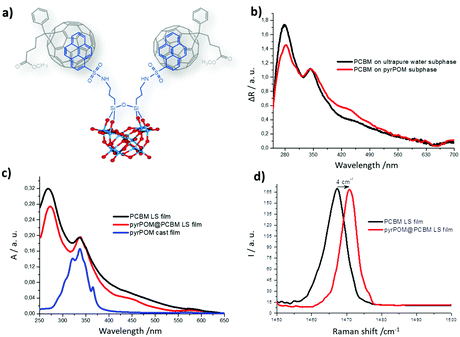
Our results address the host–guest interactions between the bis-pyrene-tagged decatungstosilicate n(Bu4N)4[{(C16H9)SO2NH(CH2)3Si}2O(γ-SiW10O36)] (hereafter named pyrPOM) and PCBM (Fig. 1 and Fig. S1, ESI†), their binding stoichiometry and the multi-redox behavior of the molecular assembly. The resulting supramolecular film behaves as a tunable dipole layer, exhibiting ferroelectric polarization properties to induce a strong electric field into the A:D photoactive layers and tune their energy levels for increasing the OPV efficiency.29
The co-localization of the inorganic POM scaffold with the fullerene cores, regulated by the bis-pyrene tweezer receptor is expected to direct the IFL molecular architecture and morphology, while imparting a favorable polarization of the charge density between the organic–inorganic domains. The ordering of pyrPOM:PCBM architecture lies at the origin of the ferroelectric behavior, as it turns out that the polarization direction can be switched between two opposite states upon application of a voltage pulse.28
Moreover, the pyrene-tagged building blocks can enable efficient energy transfer to the fullerene cores and shape nano-domains fostering charge transport with enhanced current density and charge collection by the cell electrodes.30
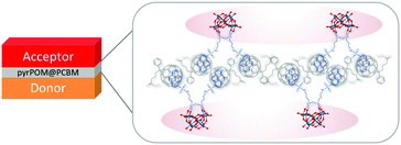
The resulting pyrPOM@PCBM films show an interesting piezoresponse, typical of ferroelectric materials. Such a behavior was reflected also into a change of pyrPOM@PCBM films’ optical absorbance of a polarized light and, when incorporated in a bilayer donor/acceptor thin film photovoltaic device (Fig. 1), promotes a significant enhancement of both open circuit voltage and fill factor. Such improvements are further increased when the interlayer is polarized by means of an external bias, recording an increasing of Voc up to 34% in comparison with the classic donor/acceptor configuration.
Results and discussion
Supramolecular adduct characterization
The supramolecular assembly between POM and PCBM, (Fig. 1) has been investigated and their mixtures have been characterized.1,31 The π electrons of the pyrene units are expected to interact with the dense π-electron cloud of the fullerene moiety of PCBM.32A solution of PCBM in ortho-dichlorobenzene (o-DCB, 5 × 10⁻³ M) was added stepwise (4 μL at each step), to a pyrPOM dimethylformamide (DMF, 10 μM) solution. The fluorescence spectrum of pyrPOM, (350 nm excitation wavelength), shows three bands centered at 379, 397, 405 nm and a shoulder at about 416 nm (Fig. S2b, ESI†).33 The excimer emission, observed at 450–500 nm, indicates a pyrene-driven aggregation in DMF environment.34
Changes in the UV-Vis spectrum are observed in the presence of PCBM (Fig. S2a, ESI†) and, simultaneously, a fluorescence quenching of pyrPOM (λex = 350 nm) is recorded (Fig. S2b, ESI†) as a consequence of the host–guest π–π interaction between the two species.
A stoichiometric ratio between pyrPOM and PCBM of 1![[thin space (1/6-em)]](https://www.rsc.org/images/entities/char_2009.gif) :
:![[thin space (1/6-em)]](https://www.rsc.org/images/entities/char_2009.gif) 2 was calculated by means of the Job's plot (Fig. S2c, ESI†), suggesting the supramolecular arrangement reported in Fig. 2a. A linear Stern–Volmer plot was also obtained monitoring the fluorescence intensity ratio at 397 nm as a function of PCBM concentration (Fig. S2d, ESI†), where a binding constant of about 4.38 × 10⁴ M−1 was obtained, which is consistent with the expected pyrene-driven host–guest interaction.28
2 was calculated by means of the Job's plot (Fig. S2c, ESI†), suggesting the supramolecular arrangement reported in Fig. 2a. A linear Stern–Volmer plot was also obtained monitoring the fluorescence intensity ratio at 397 nm as a function of PCBM concentration (Fig. S2d, ESI†), where a binding constant of about 4.38 × 10⁴ M−1 was obtained, which is consistent with the expected pyrene-driven host–guest interaction.28
The pyrPOM@PCBM system and the isolated components were analyzed by cyclic voltammetry (CV) in DMF solution between 1.5 V and −1.7 V (vs. Ag/Ag+, Fig. S3, ESI†). The CV of PCBM (1 mM) displays three well defined and reversible mono-electronic reduction waves, showing the typical electron accepting features of the fullerene core, with half-wave potentials, E1/2 = −0.246; −0.709; −1.330 V vs. Ag/Ag+.35 For pyrPOM (0.5 mM), the main reduction wave of the hybrid POM scaffold (E1/2 = −0.747 V vs. Ag+/Ag+), is ascribed to the W6+/W5+ couple36 while the irreversible anodic peak with potential, Epa = +1.27 V (vs. Ag+/Ag+) is due to the oxidation of the pyrene tweezer. The electrochemical behavior of the pyrPOM@PCBM is the result of a strong interplay of the two redox active building blocks. As a matter of fact, the characteristic pattern given by the three reversible reduction bands of PCBM becomes much less defined, being the first reduction band of PCMB shifted, by the presence of pyrPOM donor, towards more negative potentials (−90 mV, see Fig. S3, ESI†).
The formation of a pyrPOM@PCBM supramolecular adduct has been promoted directly at the air/water interface of a Langmuir Trough. PCBM was dissolved in a chloroform solution with a concentration of 10−4 M; a solution of pyrPOM (10−6 M) in ultrapure water was used as subphase in the Langmuir experiments. The Langmuir–Blodgett (LB) technique and its horizontal variation, the Langmuir–Schaefer (LS) method, were used. These two methods ensure a high control of the deposition parameters, which can be a fundamental aspect for the performance of electronic devices.37
The PCBM chloroform solution was spread by means of a gas-tight syringe on the surface of the aqueous subphase containing pyrPOM. The π–π interaction between the two species is evident by the isotherm curves of the PCBM floating film (Fig. S4, ESI†). Furthermore, a comparison between the absorption spectra of the PCBM Langmuir film evidences a variation of the ratio between the absorption bands at 344 nm and 277 nm (Fig. 2b). The highlighted band ratio variation confirms the formation of the supramolecular adduct pyrPOM@PCBM in the Langmuir film, since only the chromophores migrated at the interface can be detected by the spectrophotometer. The floating film has been transferred by means of the Langmuir–Schaefer method on a quartz substrate. The comparison of UV-Vis spectra registered for PCBM deposited from ultrapure water and from the pyrPOM containing subphase shows a variation of the band ratio observed for the floating films. This confirms the transfer of the pyrPOM@PCBM adduct (Fig. 2c). As a further proof of the supramolecular interaction, the Raman spectra of the LS films of PCBM and of the pyrPOM@PCBM adduct are compared in Fig. 2d. A 4 cm−1 shift towards higher frequencies is observed when the supramolecular adduct is formed. According to the literature, this shift suggests the formation of a supramolecular complex that does not impact on the nature of the fullerene derivatives.38
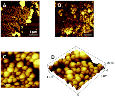
Large areas of the sample surface were scanned by AFM and the morphologies of 1 run LS films of PCBM and pyrPOM@PCBM appear very different (Fig. 3). PCBM thin films partially cover the substrate surface and appear to be formed by small aggregates (Fig. 3A). pyrPOM@PCBM film is formed by globular structures arranged in domains of approximately 200 nm (Fig. 3B and C). Furthermore, as reported in Fig. 3D, the aggregates are approximately 20 nm high.
A drastic change of optical parameters of the pyrPOM@PCBM film LS film has been recorded by ellipsometry measurements: the optical parameters of the PCBM LS film can be fit using two Lorentz oscillators. Instead, the pyrPOM@PCBM LS film was studied by two Lorentz oscillators and a Drude model in order to obtain a better data fit (Fig. S5 and S6, ESI†). Furthermore, the Maxwell–Garnett model39 has been used to evaluate the ratio between pyrPOM and PCBM within the LS film, where a 1![[thin space (1/6-em)]](https://www.rsc.org/images/entities/char_2009.gif) :
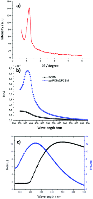
:![[thin space (1/6-em)]](https://www.rsc.org/images/entities/char_2009.gif) 2 ratio was calculated, in agreement with the value obtained in solution (see ESI†). Again, ellipsometry data have been used to estimate the thickness of each transferred LS layer, and a 8.0 ± 0.6 nm thickness was calculated for the LS pyrPOM@PCBM film. Such a result has been confirmed by means of X-ray diffraction, carried out in grazing angle configuration (see Fig. 4a). A well-defined peak at 1.2 ± 0.1 degrees indicates a periodicity of 7.6 ± 0.2 nm. On the contrary, the PCBM LS film does not show any ordered structure.
2 ratio was calculated, in agreement with the value obtained in solution (see ESI†). Again, ellipsometry data have been used to estimate the thickness of each transferred LS layer, and a 8.0 ± 0.6 nm thickness was calculated for the LS pyrPOM@PCBM film. Such a result has been confirmed by means of X-ray diffraction, carried out in grazing angle configuration (see Fig. 4a). A well-defined peak at 1.2 ± 0.1 degrees indicates a periodicity of 7.6 ± 0.2 nm. On the contrary, the PCBM LS film does not show any ordered structure.
Polarizability modulation and opto-electronics behavior
It is particularly interesting to compare the dielectric loss (tan![[thin space (1/6-em)]](https://www.rsc.org/images/entities/char_2009.gif) δ), defined as the ratio between the imaginary and real part of the dielectric function, of the LS films of pyrPOM@PCBM and of PCBM as a function of the incident electric field (Fig. 4b). The dielectric loss of PCBM LS film is very low and monotonically increasing in the range of energy investigated. On the contrary, the dielectric loss of pyrPOM@PCBM LS film reaches a maximum value at 375 nm. It may be supposed that, even though the absorption bands of pyrPOM and PCBM overlap at 375 nm, mainly pyrPOM electron clouds are influenced in the charge displacement when the electromagnetic wave is incident on the sample. A possible rationale of such a phenomenon is given considering pyrPOM@PCBM as a heterogeneous molecular domain with a semiconducting behavior. An oscillating electric field induces an accumulation of polaron species of opposite charges at the opposite edges of the nanodomain, thus creating an electric dipole. At higher frequencies, polarons cannot follow the electrical field, and the dielectric permittivity becomes negligible (Fig. 4c).40,41
δ), defined as the ratio between the imaginary and real part of the dielectric function, of the LS films of pyrPOM@PCBM and of PCBM as a function of the incident electric field (Fig. 4b). The dielectric loss of PCBM LS film is very low and monotonically increasing in the range of energy investigated. On the contrary, the dielectric loss of pyrPOM@PCBM LS film reaches a maximum value at 375 nm. It may be supposed that, even though the absorption bands of pyrPOM and PCBM overlap at 375 nm, mainly pyrPOM electron clouds are influenced in the charge displacement when the electromagnetic wave is incident on the sample. A possible rationale of such a phenomenon is given considering pyrPOM@PCBM as a heterogeneous molecular domain with a semiconducting behavior. An oscillating electric field induces an accumulation of polaron species of opposite charges at the opposite edges of the nanodomain, thus creating an electric dipole. At higher frequencies, polarons cannot follow the electrical field, and the dielectric permittivity becomes negligible (Fig. 4c).40,41
As a further characterization, piezoelectric properties of the pyrPOM@PCBM LS film have been studied by means of piezoelectric force microscopy (PFM, Fig. S7, ESI†). Two LS runs of pyrPOM@PCBM scanned by PFM clearly highlighted the presence of nanograins within the thin film (Fig. S7a, ESI†). Further, the phase difference induced by the piezopotential is very close to 180° (Fig. S7b, ESI†).42 Such a feature, already observed in LB and LS film of the known ferroelectric polymer P(VDF-TrFE)43,44 suggests the ferroic nature of the film. Besides, piezoelectric feature proposes such a material as an interesting IFL in organic photovoltaic devices.29,45,46
The possibility to modulate the dielectric function and the polarization domain of the pyrPOM@PCBM layers, according to the PFM and ellipsometric measurements, was investigated. Absorbance spectra of LS pyrPOM@PCBM film, using a p-polarized light as incident light (see Fig. 5), were acquired upon alternate application of −10 V and +10 V external bias. The absorbance of the thin film appears directly connected to the applied voltage and the response was reproducible in a series of repeated experiments.
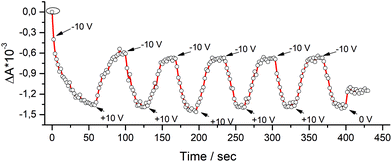 | ||
| Fig. 5 The absorbance value of pyrPOM@PCBM LS film of a p-polarized light is dependent on the applied voltage and the optical response is repeatable. | ||
In Fig. 5 the ΔOD of the pyrPOM@PCBM LS film under a vertically polarized light at 280 nm has been acquired each 2 seconds, under the application of a voltage, as external trigger. A polarization is induced in the presence of a negative potential (−10 V) that reduces the absorption of the incident polarized light; when the applied voltage is changed in sign (+10 V) the thin film absorbance at 280 nm increases, suggesting that the polarization of the formed dyad is influenced by the external bias, behavior typical of ferroelectric materials.
Donor/acceptor and donor/pyrPOM@PCBM/acceptor photovoltaic devices
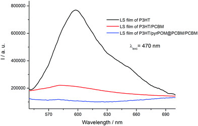
Ferroelectric organic and hybrid materials have been largely used for improving the performance of solar devices both as interface layer transferred on the cell electrodes and as interlayer between the donor and the acceptor films. The presence of a ferroelectric interlayer promotes an output photovoltage proportional to the magnitude of the electric polarization.47–50 It is reported that a direct consequence of the polarized ferroelectric interlayer can significantly enhance the open circuit voltage (Voc) of the solar device.51,52 A P3HT Langmuir film was formed by spreading 150 μL (10−4 M, deposition surface pressure: 14 mN m−1) on ultrapure water subphase and transferred by 15 runs on an ITO substrate by means of the Langmuir–Schaefer method. Then, a PCBM Langmuir–Schaefer film (15 runs, spreading volume: 130 μL, deposition surface pressure: 16 mN m−1) was deposited directly onto the ITO/P3HT structure and the electron charge transfer from the donor layer (P3HT) to the acceptor one (PCBM) was monitored by means of fluorescence spectroscopy using an excitation wavelength of 470 nm, corresponding to the maximum absorption of P3HT. The electron transfer from the electron donor to the electron acceptor induces the quenching of the polythiophene derivative fluorescence (Fig. 6).53 Two LS runs of pyrPOM@PCBM were transferred between the P3HT and PCBM LS films and the effect of the interlayer on the electronic communication among the donor and acceptor layer was monitored. As reported in Fig. 6, the fluorescence quenching is preserved in the presence of the pyrPOM@PCBM interlayer confirming the charge transfer from the polythiophene derivative towards PCBM LS layer.A platinum electrode was evaporated onto the top of the ITO/P3HT/pyrPOM@PCBM/PCBM structure and an external bias was applied.
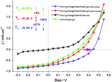
The performances of the photovoltaic devices with and without the pyrPOM@PCBM interlayer were evaluated (Fig. 7). In agreement with the spectroscopic results, the interlayer does not affect the photocurrent generation improving the open circuit voltage of about 9% if compared with Voc of ITO/P3HT/PCBM/Pt device. In a piezoelectric material the Weiss domains can be aligned using the process of poling, that is the application of an external bias across the material.54 An external bias of ±5 V was applied across the solar device both in forward (negative pole on Pt electrode) and in reverse (positive pole on Pt electrode) mode.
Poling the ITO/P3HT/pyrPOM@PCBM/PCBM/Pt device unequivocally improves the efficiency of the solar cell. At the same time the Voc increases from 0.32 V of the ITO/P3HT/pyrPOM@PCBM/PCBM/Pt without poling up to 0.44 V after poling, increasing the open circuit voltage of about 27%.
Experimental
The pyrPOM (nBu4N)4[{(C16H9)SO2NH(CH2)3Si}2O(γ-SiW10O36)] was prepared as previously described.28Cyclic voltammetry experiments were performed by using an Autolab potentiostat/galvanostat (Model 302N) equipped with a three-electrode cell (working electrode: glassy carbon, reference electrode: Ag/AgCl (NaCl 3 M); counter electrode: platinum wire. In all cases, the samples were dissolved in anhydrous DMF, TBAP (tetrabutylammonium perchlorate) was added as supporting electrolyte (0.10 M), and the solutions were degassed for 15 min under N2 flow before the measurements. Potentials are expressed with reference to Ag/Ag+ electrode.
Langmuir experiments and reflection spectra have been carried out by a NIMA500 trough. Barriers’ speed was fixed at 5 mm min−1 in all the air/subphase interface experiments. All the substrates were cleaned with chloroform/acetone/ethanol/ultrapure water (three times) before use for transferring the Langmuir–Schaefer films.
Ellipsometric measurements have been performed at multiple wavelengths at 55° angle of incidence by means of an EP4 Accurion Instrument. Models used to simulate the optical data are two Lorentz oscillators in the case of PCBM film and two Lorentz oscillators and a Drude model for pyrPOM@PCBM LS film.
Finally, XRD measurements have been realized by a Rigaku Ultima+ diffractometer in the grazing angle geometry.
Lapped Si/SiO2 substrate was used to deposit the LS films for the morphological analysis by means of an Atomic and Piezoelectric Force Microscopy (AFM/PFM) instrument (SmartSPM 1000 AIST-NT HORIBA).
UV-Visible spectra on LS films have been recorded by a Cary 5000 equipped with a linear polarizer. Infrared measurements have been carried out by a PerkinElmer Spectrum One with a multireflection tool. Each spectrum was averaged on 64 scans. Fluorescence spectra were recorded using Horiba Fluorolog spectrofluorometer. For IV characterization a Keithley 200 has been used. Raman spectra were recorded by a Horiba Explora microRaman, with an excitation laser of 785 nm.
By means of a Keithley 6517A electrometer the acquisition of the signals output voltage, that derives from the mechanical deformation induced by the movement down-up of an electromagnet driven by a function generator in the 0.01–100 Hz frequency range, has been obtained. To quantitatively evaluate the sensitivity, a microbalance KERN well-defined levels of pressure to the samples has been employed.
For photoelectrical characterization, ITO/(active layer)/I−, I3−/Pt–ITO photoelectrochemical cells were constructed, modifying a previously reported procedure.55 To prepare the counter electrode, a platinum catalyst was deposited on the ITO glass by coating with 1 drop of a 0.35 mM H2PtCl6 solution (2 mg of platinum in 1 mL of ethanol) and heating at 400 °C for 15 min. The electrolyte employed was a solution of 0.5 M LiI and 0.01 M I2 in acetonitrile. A Keithley 2400 multimeter was used for recording the IV curve and AM 1.5 solar simulator (Quantum Design) was used.
Conclusions
A supramolecular dyad formed by a di-vacant Keggin-type decatungstosilicate bisfunctionalized with pyrene and PCBM was assembled by means of π–π interactions between the the fullerene derivative and the pyrene POM and transferred on solid substrates by means of the Langmuir–Schaefer approach. The supramolecular dyad formation was confirmed by means of reflection spectroscopy (at the air/subphase interface), UV-Visible, XRD, fluorescence, ellipsometry and Raman spectroscopy. Furthermore, AFM investigations showed an evident change in the morphology when the LS film of PCBM was transferred from the water subphase containing pyrPOM. The supramolecular dyad immobilized on solid substrates showed polarization-dependent features that suggest its use for applications in photovoltaic devices. PFM analysis suggests the presence of piezo-responsive nanograins typical of ferroelectric materials. In fact, the dyad film showed absorbance features upon p-polarized light excitation sensitive to the application of an external bias. In particular, it was demonstrated that the presence of the pyrPOM@PCBM interlayer deposited between a P3HT donor LS film and PCBM (as acceptor layer) enhances the Voc of the solar device by about 34% if suitably polarized.Author contributions
The manuscript was written through contributions of all authors. Gabriele Giancane: data analysis, writing – review and editing. Simona Bettini: data measurement and analysis, writing – original draft; Ludovico Valli: analysis and discussion of experimental results, supervision, writing – review and editing. Victoria Bracamonte: electrochemical experiments. Mauro Carraro: synthesis, writing – review and editing. Marcella Bonchio: analysis and discussion of experimental results, supervision, writing – review and editing. Maurizio Prato: analysis and discussion of experimental results, supervision, writing – review and editing.Conflicts of interest
There are no conflicts to declare.Acknowledgements
This research was supported by the PRIN 2017 (protocol number 2017PBXPN4), by the European Innovation Council through the INITIO-FET Project INITIO (Grant Agreement: 828779) and by “Research for Innovation” POR PUGLIA FESR-FSE 2014/2020 Ricerca Regione Puglia. Part of this work was performed under the Maria de Maeztu Units of Excellence Program from the Spanish State Research Agency Grant No. MDM-2017-0720.References
- J. C. Hummelen, B. W. Knight, F. Lepeq, F. Wudl, J. Yao and C. L. Wilkins, J. Org. Chem., 1995, 60, 532–538 CrossRef CAS.
- H. Lee, C. Park, D. H. Sin, J. H. Park and K. Cho, Adv. Mater., 2018, 30, 1800453 CrossRef PubMed.
- L. Dou, J. You, Z. Hong, Z. Xu, G. Li, R. A. Street and Y. Yang, Adv. Mater., 2013, 25, 6642–6671 CrossRef CAS.
- D. H. Wang, A. K. K. Kyaw, J. R. Pouliot, M. Leclerc and A. J. Heeger, Adv. Energy Mater., 2014, 4, 1300835 CrossRef.
- K. M. Pelzer and S. B. Darling, Mol. Syst. Des. Eng., 2016, 1, 10–24 RSC.
- S. Few, J. M. Frost and J. Nelson, Phys. Chem. Chem. Phys., 2015, 17, 2311–2325 RSC.
- T. M. Clarke and J. R. Durrant, Chem. Rev., 2010, 110, 6736–6767 CrossRef CAS.
- J. Yu, Y. Zheng and J. Huang, Polymers, 2014, 6, 2473–2509 CrossRef.
- S. H. Liao, Y. L. Li, T. H. Jen, Y. S. Cheng and S. A. Chen, J. Am. Chem. Soc., 2012, 134, 14271–14274 CrossRef CAS PubMed.
- J. H. Seo, A. Gutacker, Y. Sun, H. Wu, F. Huang, Y. Cao, U. Scherf, A. J. Heeger and G. C. Bazan, J. Am. Chem. Soc., 2011, 133, 8416–8419 CrossRef CAS PubMed.
- M. Carraro, G. Bergamini, M. Di Lauro, G. Modugno, M. Baroncini, P. Ceroni and M. Bonchio, Eur. J. Inorg. Chem., 2016, 3405–3410 CrossRef CAS.
- Z. Syrgiannis, G. Trautwein, M. Calvaresi, G. Modugno, F. Zerbetto, M. Carraro, M. Prato and M. Bonchio, Eur. J. Inorg. Chem., 2019, 374–379 CrossRef CAS.
- L. C. Palilis, M. Vasilopoulou, D. G. Georgiadou and P. Argitis, Org. Electron., 2010, 11, 887–894 CrossRef CAS.
- M. Vasilopoulou, A. M. Douvas, L. C. Palilis, S. Kennou and P. Argitis, J. Am. Chem. Soc., 2015, 137, 6844–6856 CrossRef CAS PubMed.
- L. C. Palilis, M. Vasilopoulou, A. M. Douvas, D. G. Georgiadou, S. Kennou, N. A. Stathopoulos, V. Constantoudis and P. Argitis, Sol. Energy Mater. Sol. Cells, 2013, 114, 205–213 CrossRef CAS.
- M. Vasilopoulou, E. Polydorou, A. M. Douvas, L. C. Palilis, S. Kennou and P. Argitis, Energy Environ. Sci., 2015, 8, 2448–2463 RSC.
- X. Jia, L. Shen, M. Yao, Y. Liu, W. Yu, W. Guo and S. Ruan, ACS Appl. Mater. Interfaces, 2015, 7, 5367–5372 CrossRef CAS.
- Y. Zhu, Z. Yuan, W. Cui, Z. Wu, Q. Sun, S. Wang, Z. Kang and B. Sun, J. Mater. Chem. A, 2014, 2, 1436–1442 RSC.
- M. Alaaeddine, Q. Zhu, D. Fichou, G. Izzet, J. E. Rault, N. Barrett, A. Proust and L. Tortech, Inorg. Chem. Front., 2014, 1, 682–688 RSC.
- M. Tountas, Y. Topal, E. Polydorou, A. Soultati, A. Verykios, A. Kaltzoglou, T. A. Papadopoulos, F. Auras, K. Seintis, M. Fakis, L. C. Palilis, D. Tsikritzis, S. Kennou, M. Koutsoureli, G. Papaioannou, M. Ersöz, M. Kus, P. Falaras, D. Davazoglou, P. Argitis and M. Vasilopoulou, ACS Appl. Mater. Interfaces, 2017, 9, 22773–22787 CrossRef CAS PubMed.
- B. A. Collins, Z. Li, J. R. Tumbleston, E. Gann, C. R. Mcneill and H. Ade, Adv. Energy Mater., 2013, 3, 65–74 CrossRef CAS.
- J. Guo, H. Ohkita, H. Benten and S. Ito, J. Am. Chem. Soc., 2010, 132, 6154–6164 CrossRef CAS PubMed.
- P. Westacott, J. R. Tumbleston, S. Shoaee, S. Fearn, J. H. Bannock, J. B. Gilchrist, S. Heutz, J. Demello, M. Heeney, H. Ade, J. Durrant, D. S. McPhail and N. Stingelin, Energy Environ. Sci., 2013, 6, 2756–2764 RSC.
- S. Sweetnam, K. R. Graham, G. O. Ngongang Ndjawa, T. Heumüller, J. A. Bartelt, T. M. Burke, W. Li, W. You, A. Amassian and M. D. McGehee, J. Am. Chem. Soc., 2014, 136, 14078–14088 CrossRef CAS.
- S. Mukherjee, X. Jiao and H. Ade, Adv. Energy Mater., 2016, 6, 1600699 CrossRef.
- W. Chen, T. Xu, F. He, W. Wang, C. Wang, J. Strzalka, Y. Liu, J. Wen, D. J. Miller, J. Chen, K. Hong, L. Yu and S. B. Darling, Nano Lett., 2011, 11, 3707–3713 CrossRef CAS PubMed.
- D. Baran, R. S. Ashraf, D. A. Hanifi, M. Abdelsamie, N. Gasparini, J. A. Röhr, S. Holliday, A. Wadsworth, S. Lockett, M. Neophytou, C. J. M. Emmott, J. Nelson, C. J. Brabec, A. Amassian, A. Salleo, T. Kirchartz, J. R. Durrant and I. McCulloch, Nat. Mater., 2017, 16, 363–369 CrossRef CAS PubMed.
- G. Modugno, Z. Syrgiannis, A. Bonasera, M. Carraro, G. Giancane, L. Valli, M. Bonchio and M. Prato, Chem. Commun., 2014, 50, 4881–4883 RSC.
- B. Yang, Y. Yuan, P. Sharma, S. Poddar, R. Korlacki, S. Ducharme, A. Gruverman, R. Saraf and J. Huang, Adv. Mater., 2012, 24, 1455–1460 CrossRef CAS.
- B. Kadem, E. N. Kaya, A. Hassan, M. Durmuş and T. Basova, Sol. Energy, 2019, 189, 1–7 CrossRef CAS.
- M. C. Scharber, D. Mühlbacher, M. Koppe, P. Denk, C. Waldauf, A. J. Heeger and C. J. Brabec, Adv. Mater., 2006, 18, 789–794 CrossRef CAS.
- F. M. Toma, A. Sartorel, M. Iurlo, M. Carraro, S. Rapino, L. Hoober-Burkhardt, T. Da Ros, M. Marcaccio, G. Scorrano, F. Paolucci, M. Bonchio and M. Prato, ChemSusChem, 2011, 4, 1447–1451 CrossRef CAS PubMed.
- J. González-Benito, J. C. Cabanelas, A. Aznar, M. R. Vigil, J. Bravo, B. Serrano and J. Baselga, J. Lumin., 1997, 72–74, 451–453 CrossRef.
- F. Winnik, Chem. Rev., 1993, 93, 587–614 CrossRef CAS.
- G. D. Han, W. R. Collins, T. L. Andrew, V. Bulovi
![[c with combining umlaut]](https://www.rsc.org/images/entities/char_0063_0308.gif) and T. M. Swager, Adv. Funct. Mater., 2013, 23, 3061–3069 CrossRef CAS.
and T. M. Swager, Adv. Funct. Mater., 2013, 23, 3061–3069 CrossRef CAS. - G. Modugno, A. Monney, M. Bonchio, M. Albrecht and M. Carraro, Eur. J. Inorg. Chem., 2014, 2356–2360 CrossRef CAS.
- T. L. Penner, H. R. Motschmann, N. J. Armstrong, M. C. Ezenyilimba and D. J. Williams, Nature, 1994, 367, 49–51 CrossRef CAS.
- M. Behera and S. Ram, J. Inclusion Phenom. Macrocyclic Chem., 2012, 72, 233–239 CrossRef CAS.
- M. Y. Koledintseva, S. K. R. Chandra, R. E. DuBroff and R. W. Schwartz, Prog. Electromagn. Res., 2006, 66, 213–228 CrossRef.
- S. Dang, J. Phys. D: Appl. Phys., 2008, 41, 125101 CrossRef.
- W. Hu, L. Li, W. Tong, G. Li and T. Yan, J. Mater. Chem., 2010, 20, 8659–8667 RSC.
- C. Liu, J. Ma, J. Ma, Y. Zhang, J. Chen and C. W. Nan, AIP Adv., 2017, 7, 055003 CrossRef.
- P. Sharma, T. Reece, D. Wu, V. M. Fridkin, S. Ducharme and A. Gruverman, J. Phys.: Condens. Matter, 2009, 21, 485902 CrossRef CAS.
- P. Sharma, A. Fursina, S. Poddar, S. Ducharme and A. Gruverman, Appl. Phys. Lett., 2014, 105, 182903 CrossRef.
- C. R. Bowen, H. A. Kim, P. M. Weaver and S. Dunn, Energy Environ. Sci., 2014, 7, 25–44 RSC.
- M. Zheng, Q. Xu, R. Tian and C. Lu, J. Colloid Interface Sci., 2021, 600, 473–479 CrossRef CAS PubMed.
- Y. Yuan, Z. Xiao, B. Yang and J. Huang, J. Mater. Chem. A, 2014, 2, 6027–6041 RSC.
- Y. Hu, F. Florio, Z. Chen, W. Adam Phelan, M. A. Siegler, Z. Zhou, Y. Guo, R. Hawks, J. Jiang, J. Feng, L. Zhang, B. Wang, Y. Wang, D. Gall, E. F. Palermo, Z. Lu, X. Sun, T. M. Lu, H. Zhou, Y. Ren, E. Wertz, R. Sundararaman and J. Shi, Sci. Adv., 2020, 6, eaay4213 CrossRef CAS PubMed.
- R. R. Bai, C. R. Zhang, Z. J. Liu, X. K. Chen, Y. Z. Wu, W. Wang and H. S. Chen, Comput. Theor. Chem., 2020, 1186, 112914 CrossRef CAS.
- L. Hu, S. Dalgleish, M. M. Matsushita, H. Yoshikawa and K. Awaga, Nat. Commun., 2014, 5, 3279 CrossRef PubMed.
- S. Y. Yang, J. Seidel, S. J. Byrnes, P. Shafer, C. H. Yang, M. D. Rossell, P. Yu, Y. H. Chu, J. F. Scott, J. W. Ager, L. W. Martin and R. Ramesh, Nat. Nanotechnol., 2010, 5, 143–147 CrossRef CAS.
- T. Ahamad, A. Aldalbahi, S. M. Alshehri, S. Alotaibi, S. Alzahly, Z. B. Wang and P. X. Feng, Sol. Energy, 2021, 220, 758–765 CrossRef CAS.
- S. Bettini, S. Sawalha, L. Carbone, G. Giancane, M. Prato and L. Valli, Nanoscale, 2019, 11, 7414–7423 RSC.
- A. Roberts and R. Romanofsky, Integrated Ferroelectrics, Taylor & Francis Group, 2012, vol. 134, pp. 102–110 Search PubMed.
- S. Ito, T. N. Murakami, P. Comte, P. Liska, C. Grätzel, M. K. Nazeeruddin and M. Grätzel, Thin Solid Films, 2008, 516, 4613–4619 CrossRef CAS.
Footnote |
| † Electronic supplementary information (ESI) available. See DOI: 10.1039/d1tc03148a |
| This journal is © The Royal Society of Chemistry 2021 |

