In situ coupling of TiO2(B) and ZIF-8 with enhanced photocatalytic activity via effective defect†
Xiaoxue
Qi
a,
Feng
Shang
b,
Tao
Wang
c,
Yuqin
Ma
 *a and
Yongsheng
Yan
 *cd
*cd
aSchool of Chemistry and Environmental Engineering, Changchun University of Science and Technology, 86-130022 Changchun, Jilin Province, P. R. China. E-mail: myq3939@163.com; Tel: +15044087078
bBureau of Ecology and Environment of Changchun Jiutai Branch Office, 130022 Changchun, P. R. China
cSchool of Chemistry and Chemical Engineering, Jiangsu University, 212013 Zhenjiang, P. R. China
dInstitute of Green Chemistry and Chemical Technology, Jiangsu University, 212013 Zhenjiang, P. R. China
First published on 26th May 2020
Abstract
In recent years, photocatalytic degradation on inorganic semiconductors has been attracting widespread attention. However, for a single semiconductor, the speed of the recombination of electrons and holes is fast, which leads to a decrease in the absorption of sunlight, thereby affecting its photocatalytic efficiency. Therefore, the coupling of semiconductor and metal–organic framework is of great significance due to its porosity and large specific surface area. Herein, a composite photocatalyst was obtained by coupling ZIF-8 and TiO2(B) via a simple method. XRD, FT-IR spectroscopy, SEM, TEM, UV-visible diffuse reflectance spectroscopy, XPS, EPR and EDS were used to study the as-prepared samples. Photocatalytic degradation experiments confirmed that the composites have significantly improved photodegradation performance due to the increased light utilization and fast charge carrier transfer. Moreover, the possible mechanism of photodegradation was also proposed. This study provides an initial view on the coupling of semiconductor and metal–organic framework to enhance the photocatalytic performance.
1. Introduction
Environmental hazards and energy problems are the two major issues that have arisen along with the rapid development of industries, and have become the key challenges that mankind urgently needs to solve.1,2 Photocatalysis, a new and effective green process, converts light energy into chemical energy to provide the energy needed for reactions and oxidizes nearby water molecules and oxygen into free anions during the catalysis. Therefore, it has immeasurable application prospects in the field of environmental protection and energy utilization. Unfortunately, the development of photocatalysts limits the development of the photocatalytic technology.Semiconductor materials are currently the most widely used photocatalysts, including oxides (TiO2,3 ZnO,4 Fe2O3,5etc.), sulfides (ZnS,6 CdS,7 CuS,8etc.), and novel photocatalysts (g-C3N4,9,10 ATiO3,11 molecular sieve,12etc.).13 With the growth of research on photocatalysts, the application range of the photocatalytic technology has broadened, which can not only be used to degrade organic pollutants in wastewater into water and CO2 but also further transform water into clean H2 energy. Therefore, research on semiconductor photocatalysts is of great significance.14
TiO2 has been the most important photocatalyst in the past few decades due to its excellent chemical stability, thermal stability, good dispersibility, non-toxicity and low cost.15 However, due to its slight wide band gap and the fast recombination of electrons and holes, its practical applications are limited.16–19 In order to broaden the application of TiO2, numerous methods, including metal and non-metal doping, band gap engineering, semiconductor coupling, morphology tuning and heterojunction fabrication, have been studied to improve the shortcomings of TiO2.1,20 Among them, semiconductor coupling is the common and efficient way to make the effective use of sunlight and improve the light stability of TiO2.
Metal–organic frameworks (MOFs) are a class of multifunctional materials with repeated network structure formed via the self-assembly of organic ligands and metal ions. Because of their porosity, large specific surface area, and unsaturated metal site, MOFs and composite MOF materials have/application prospects in the catalytic applications.21–24 Therefore, continuing research and development on the multi-functional MOFs and composite MOF materials and application in different fields will greatly promote the mutual development of the disciplines.25–28 Among them, ZIF-8 is a simple and easy-to-synthesize porous material that combines the high stability of inorganic zeolites with the high porosity and organic function of MOFs, making it one of the most popular metal–organic frameworks.29,30
To date, numerous studies have been conducted to combine ZIF-8 and semiconductor to prepare a composite catalyst with higher catalytic efficiency. Li et al. reported the successful loading of CoB onto ZIF-8 via a one-step reduction method and examined its activity in the hydrogen production.31 Zhang et al. successfully synthesized TiO2@ZIF-8 hollow nanospheres with a double-shell structure by ultrasonic crystallization for photocatalytic hydrogen evolution.14 Pipelzadeh et al. prepared a new ZIF-8/TiO2 nanocomposite for the photocatalytic reduction of CO2 to CH4 and CO.32 As expected, by combining ZIF-8 and TiO2, the photocatalytic activity was greatly improved. Recently, a black TiO2 (TiO2(B)) has been reported and attracted considerable attention. Mao et al. proposed black TiO2 and found that black TiO2 has stronger absorption of sunlight than white TiO2.33 Ye et al. reported nickel-loaded black TiO2 with an inverse opal structure and used for the stable and efficient reduction of CO2.20 Therefore, it was meaningful to explore the photocatalytic activity of the TiO2(B)/ZIF-8 composite.
Unlike Zhang and Li who used pure TiO2 and ZIF-8 for coupling, in this study, we prepared a composite catalyst with high catalytic efficiency by coupling black TiO2 and ZIF-8. XRD, EDS, SEM and TEM analyses confirmed the successful combination of TiO2(B) and ZIF-8. Based on the results of Raman, UV-vis diffuse reflectance, EPR and XPS, it is proposed that the improvement of the photocatalytic activity was due to the generation of oxygen vacancies and Ti3+. Furthermore, the photocatalytic degradation mechanism of TC is also discussed. This study provides important roadmap for the continuous exploration of the application of MOF-based semiconductor composites in photocatalysis and environmental protection.
2. Experimental
2.1. Materials
All the chemicals used during the experiment did not require further purification, and deionized water was used throughout the experiment. Tetrabutyltitanate (C16H36O4Ti), sodium borohydride (NaBH4, ≥98%), zinc nitrate hexahydrate (Zn(NO3)2·6H2O, ≥99.0%), absolute ethanol (CH3CH2OH, ≥99.7%), methanol (CH4O, ≥99.5%), citric acid (C6H8O7, ≥99.7%), ascorbic acid (C6H8O6, ≥99.7%), and iso-propyl alcohol (C3H8O, ≥99.7%) were purchased from Sinopharm Chemical Reagent Co. 2-Methylimidazole (C4H6N2, ≥98%) was purchased from Aladdin Industrial Corporation.2.2. Preparation of black TiO2
Black TiO2 was prepared according to the previously reported procedure.3 3.0 mL of tetrabutyltitanate was added to a beaker containing 50 mL of deionized water. After stirring for 30 min, the mixture was poured into the reaction vessel and reacted at 180 °C for 6 h. Then, the obtained sample was centrifuged, washed 4 to 5 times with deionized water and ethanol, and dried in an oven at 60 °C to obtain white TiO2. Furthermore, 1.0 g of white TiO2 and 2.0 g of sodium borohydride were mixed and ground evenly. Then, the mixture was put into a tube furnace and calcined at 350 °C for 1 h at a heating rate of 5 °C min−1. After the temperature was naturally cooled, the calcined powder was washed for at least 5 to 6 times with deionized water until the final washing liquid became neutral, followed by drying in an oven at 60 °C to obtain black TiO2.2.3. Synthesis of the TiO2(B)/ZIF-8 composite
TiO2(B)/ZIF-8 composite was prepared via a simple method. 0.7437 g of zinc nitrate hexahydrate and 0.4105 g of 2-methylimidazole were dissolved in 50 mL of methanol, and labeled as solution A and solution B, respectively. Then, 0.03 g of black TiO2 was dissolved in solution A and ultrasonically dispersed. Thereafter, the solutions A and B were mixed with mechanical stirring at 50 °C for 1 h. The mixture was then centrifuged and washed 4 times with methanol and dried in a vacuum oven at 80 °C. Moreover, different addition amounts of TiO2(B) in the composite (0 g, 0.01 g, 0.03 g, 0.07 g, and 0.1 g) were obtained under identical conditions. Pure ZIF-8 was obtained in the absence of TiO2(B) (0 g), and the obtained composites were labeled as TiO2(B)/ZIF-8-x (x is the amount of TiO2(B)).2.4. Photocatalytic experiments
10 mg of the catalyst was dispersed in 100 mL solution containing 10 mg L−1 tetracycline, and stirred under dark conditions for 30 min to achieve an adsorption–desorption balance. Then, the visible light source was turned on to start the degradation experiment, and cold water was circulated to keep the reaction at normal temperature. The samples were taken every 15 min and centrifuged for the removal of the solid catalyst. The filtrate was measured by the UV-vis absorption spectroscopy and analyzed based on the change of the concentration of tetracycline recorded by its absorbance.3,14,342.5. Free radical scavenging test
To determine the role of the reactive substances in the photodegradation of tetracycline, the free radical scavenging experiments were carried out. The effects of holes, hydroxyl radicals and superoxide radicals on the photodegradation were studied using citric acid, ascorbic acid and iso-propyl alcohol, respectively. A certain amount of the scavenger was added in each experiment, keeping the experimental conditions the same as the previous photocatalytic experiments.353. Results and discussion
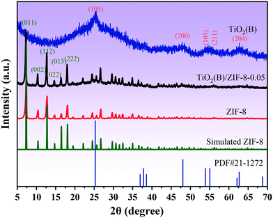
XRD was used to analyze the crystal structure of the as-prepared sample. Fig. 1 shows the XRD patterns of the TiO2(B), ZIF-8, and TiO2(B)/ZIF-8 composites. The characteristic peaks of TiO2(B) were observed at 25.36°, 47.86°, 53.96°, 55.86°, and 62.74°, which were attributed to the (101), (200), (105), (211), and (204) crystal planes of TiO2 (PDF# 71-1167), respectively.3 According to the ZIF-8 simulated card, it can be seen that the as-prepared sample exhibited the characteristic peaks at 7.26°, 10.3°, 12.6°, 14.68°, 16.4°, 18.0° which were attributed to the (011), (002), (112), (022), (013) and (222) crystal planes of ZIF-8, and were consistent with the previous reports.14,30 For the composite TiO2(B)/ZIF-8, the XRD pattern shows all the characteristic diffraction peaks of ZIF-8, without any clear characteristic peak of TiO2(B) due to the weak peak intensity of the nanosized TiO2(B). SEM and TEM were further used to prove the XRD results.The morphology and size of the samples were analyzed via SEM and TEM. The SEM image of ZIF-8 is shown in Fig. 2a; its shape was a regular dodecahedron with uniform size and distribution. Fig. 2b shows the TEM image of TiO2(B), which can be found to be about 10 nm in size, conforming to the conjecture proposed via XRD. Fig. 2c displays the SEM image of the TiO2(B)/ZIF-8 composite, which indicates that the crystal structure of ZIF-8 was not destroyed after combination with TiO2(B), and the dodecahedral structure was maintained. No significant TiO2(B) was observed in the SEM image due to the nanometer size of TiO2(B), but it can be clearly seen in the TEM image (Fig. 2d) of the composite that TiO2(B) was attached to the surface of ZIF-8. In addition, the elemental composition of the TiO2(B)/ZIF-8 composite was determined via EDS. As shown in Fig. S1,† five elements (C, N, Ti, O and Zn) were detected in the composite, further indicating that the composite was successfully synthesized.30
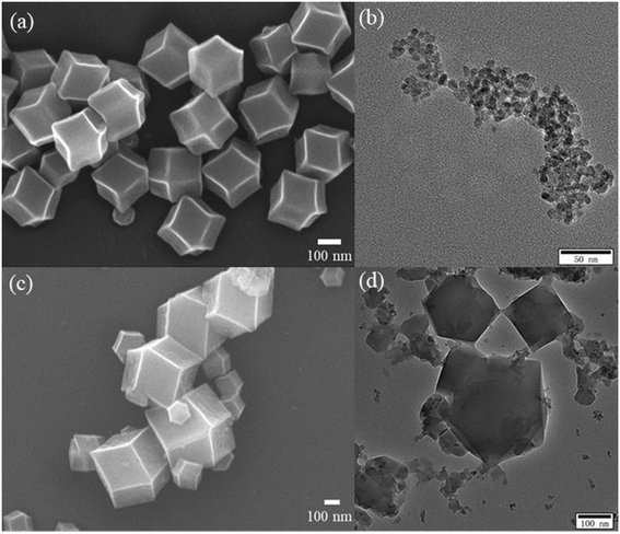 | ||
| Fig. 2 SEM image of ZIF-8 (a) and TEM image of TiO2(B) (b), SEM and TEM images of TiO2(B)/ZIF-8 (c and d). | ||
FTIR spectroscopy was performed to analyze the chemical bonds present on the samples. Fig. 3a shows the FT-IR spectra of TiO2(B), ZIF-8 and TiO2(B)/ZIF-8. The vibrational bands of the as-prepared ZIF-8 at 422 cm−1 and 1584 cm−1 were assigned to the Zn–N and C![[double bond, length as m-dash]](https://www.rsc.org/images/entities/char_e001.gif) N stretching vibrations, respectively. The peaks appearing at 1423 cm−1 and 995 cm−1 are due to the stretching vibrations of C–N, and the vibration bands at 1147 cm−1 and 1310 cm−1 were due to the bending vibration of imidazole.14,29 These are the typical characteristics of ZIF-8. For pure TiO2(B), the vibrational zone between 400–700 cm−1 is attributed to the typical Ti–O–Ti bond vibration and Ti–O stretching vibration mode. The hydroxyl group resulted in a peak at 1632 cm−1, and the peak between 3400 and 3500 cm−1 was due to the physical absorption of water on the surface of TiO2(B).3 All the characteristic peaks of TiO2(B) and ZIF-8 are present in the composite, indicating that the composite was successfully synthesized.3,14,30,34Fig. 3b shows the characteristic Raman spectra of TiO2(B), ZIF-8 and TiO2(B)/ZIF-8. The peaks at 685.46 cm−1 and 1000–1600 cm−1 in ZIF-8 are caused by the imidazole ring vibration, C–H sway, C5–N stretching vibration and C4–C5 stretching mode.29 As shown by the Raman spectrum of TiO2(B), the peaks at 161 cm−1 and 632 cm−1 belong to the Eg mode, and the peaks at 398 cm−1 and 516 cm−1 belong to the B1g and A1g modes, respectively. This was consistent with the crystal structure of TiO2(B).36 Compared to TiO2(B), the TiO2(B)/ZIF-8 composite has a slight redshift, which was caused by the decrease in the grain size and oxygen vacancies during the reaction.14,34
N stretching vibrations, respectively. The peaks appearing at 1423 cm−1 and 995 cm−1 are due to the stretching vibrations of C–N, and the vibration bands at 1147 cm−1 and 1310 cm−1 were due to the bending vibration of imidazole.14,29 These are the typical characteristics of ZIF-8. For pure TiO2(B), the vibrational zone between 400–700 cm−1 is attributed to the typical Ti–O–Ti bond vibration and Ti–O stretching vibration mode. The hydroxyl group resulted in a peak at 1632 cm−1, and the peak between 3400 and 3500 cm−1 was due to the physical absorption of water on the surface of TiO2(B).3 All the characteristic peaks of TiO2(B) and ZIF-8 are present in the composite, indicating that the composite was successfully synthesized.3,14,30,34Fig. 3b shows the characteristic Raman spectra of TiO2(B), ZIF-8 and TiO2(B)/ZIF-8. The peaks at 685.46 cm−1 and 1000–1600 cm−1 in ZIF-8 are caused by the imidazole ring vibration, C–H sway, C5–N stretching vibration and C4–C5 stretching mode.29 As shown by the Raman spectrum of TiO2(B), the peaks at 161 cm−1 and 632 cm−1 belong to the Eg mode, and the peaks at 398 cm−1 and 516 cm−1 belong to the B1g and A1g modes, respectively. This was consistent with the crystal structure of TiO2(B).36 Compared to TiO2(B), the TiO2(B)/ZIF-8 composite has a slight redshift, which was caused by the decrease in the grain size and oxygen vacancies during the reaction.14,34
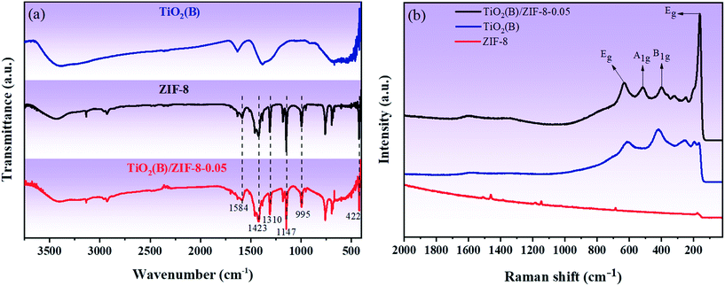 | ||
| Fig. 3 (a) FT-IR spectra of TiO2(B), TiO2(B)/ZIF-8 and ZIF-8; (b) characteristic Raman spectra of TiO2(B), ZIF-8 and TiO2(B)/ZIF-8. | ||
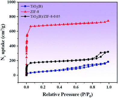
In order to characterize the porous structure and specific surface area of the as-prepared TiO2(B), ZIF-8 and composite material TiO2(B)/ZIF-8, nitrogen adsorption–desorption studies were performed. Fig. 4 shows the adsorption–desorption isotherm of the as-prepared sample. As shown in Fig. 4, the curve corresponding to ZIF-8 shows type I isotherm, indicating that it is microporous. The curve of TiO2(B) is a type IV isotherm because TiO2(B) generates voids during assembly, so it shows single-layer adsorption at a low pressure and multilayer adsorption at a high pressure.29 The composite shows a type IV isotherm, indicating a mesoporous structure. The specific surface area, pore width and pore volume of all the samples are summarized in Table 1. Compared to that of TiO2(B), the specific surface area of the composite material increases. This is because ZIF-8, as a metal–organic framework, can well-disperse TiO2(B), allowing it to be evenly distributed around its framework. A large specific surface area means that more active sites will participate in the reaction, thereby improving the efficiency and speed of the photocatalytic degradation of the pollutants.
| Samples | BET (m2 g−1) | Pore volume (cm3 g−1) | Pore width (nm) |
|---|---|---|---|
| TiO2(B) | 179.3 | 0.25 | 7.8 |
| ZIF-8 | 2831.8 | 1.05 | 1.7 |
| TiO2(B)/ZIF-8 | 710.5 | 0.46 | 5.0 |
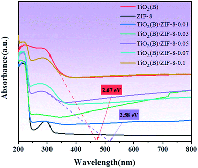
The light absorption ability of the samples was analyzed via UV-vis diffuse reflectance spectroscopy. In Fig. 5, it is observed that the absorption wavelength of ZIF-8 is at around 230 nm, which means that ZIF-8 can only respond to UV light. For TiO2(B), its absorption in the visible region significantly enhanced compared to the white TiO2 reported in the literature, which was due to the introduction of Ti3+ and oxygen vacancies.15 When ZIF-8 and TiO2(B) were combined, the TiO2(B)/ZIF-8 composite exhibits a wider absorption edge that extends into the visible region. This was due to the close contact between ZIF-8 and TiO2(B), which alters the light absorption capacity of the composite.3,14 The band gap energies of TiO2(B) and the TiO2(B)/ZIF-8 composite are also displayed in Fig. 5. Compared to ZIF-8, the band gap of TiO2(B) and all the composites were smaller. The broadened visible-light absorption would enhance the photodegradation properties of the TiO2(B)/ZIF-8 composite.
To analyze the chemical bonds and elemental composition present on the surface of the samples, XPS study was carried out. Fig. 6a shows the XPS survey spectrum of the TiO2(B)/ZIF-8 composite, confirming the presence of five elements, i.e., N, Ti, C, O, and Zn, in the composite. In the spectrum of C 1s (Fig. 6b), the peaks at 284.6 eV and 285.1 eV are due to the C–C and C–N bonds, respectively.14 As shown in Fig. 6c (N 1s), the peaks at 398.95 eV and 399.45 eV are attributed to the C–N bond and the N–Ti–O bond of the imidazole ring in ZIF-8. The N–Ti–O bond indicated that the N atoms in the imidazole ring replaced some O atoms on the TiO2(B) producing oxygen vacancies, which was consistent with the Raman results.14 It can be seen in Fig. 6d that the XPS spectrum of O 1s produces bumps at 531.3 eV and 532.3 eV due to the Ti–O bond and organic impurities, respectively.37,38Fig. 6e shows the XPS spectrum of Zn 2p, and the peaks at 1021.9 eV and 1045 eV are caused by Zn 2p3/2 and Zn 2p1/2, respectively.31,39 From Fig. 6f (Ti 2p), it can be seen that the binding energies at 458.4 eV and 464.1 eV is ascribed to Ti4+ in TiO2(B).3,40 The peak at 459.5 eV was due to the low oxidation state (Ti3+) in TiO2(B).41 Therefore, the above XPS measurement results further proved that the composite was successfully prepared and the presence of oxygen vacancies in the composite.
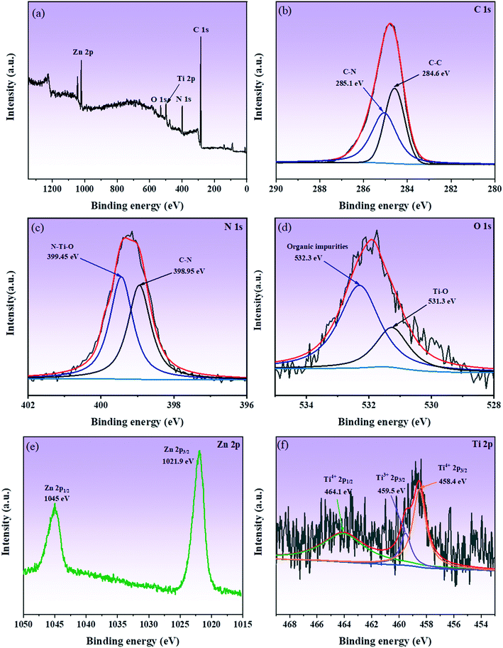 | ||
| Fig. 6 XPS survey spectrum of TiO2(B)/ZIF-8 (a); high-resolution XPS spectrum of C 1s, Zn 2p, N 1s, Ti 2p, and O 1s (b–f). | ||
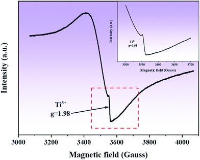
In order to detect Ti3+ and oxygen vacancies in the composite, EPR studies were conducted. Fig. 7 shows the EPR spectrum of the composite. It can be seen that in the EPR spectrum of the composite, a clear symmetric signal is detected at g = 1.98, which can be attributed to the formation of defects in the sample, such as oxygen vacancies.
Fig. 8a shows the results of electrochemical impedance spectroscopy (EIS) measurements of the three samples. Compared to ZIF-8, the TiO2(B) and TiO2(B)/ZIF-8 composites have smaller impedance arc radii, with TiO2(B) being the smallest. The small arc radius can increase the electron transfer speed and further improve the photocatalytic activity of the TiO2(B)/ZIF-8 composites. Fig. 8b displayed the photocurrent intensity of all the samples. Although TiO2(B) has the smallest impedance arc radius and the strongest photocurrent, as shown in Fig. 8b, its photocurrent intensity will gradually decrease with time. The photocurrent intensity of the TiO2(B)/ZIF-8 composite was almost constant, demonstrating that the composite has better stability than TiO2(B).
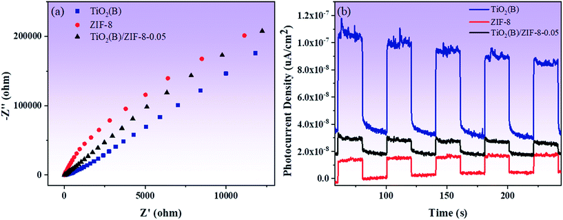 | ||
| Fig. 8 Electrochemical impedance spectra (a) and photocurrent intensity (b) of TiO2(B), ZIF-8 and TiO2(B)/ZIF-8, respectively. | ||
Fig. 9a shows the photocatalytic degradation of TC in presence of different photocatalysts. For ZIF-8 and TiO2(B), the concentration of TC decreased by only 10% and 22% after 90 min under visible light irradiation. Compared with ZIF-8 and TiO2(B), all the composites have good degradation effects. Also, with the increase in the amount of TiO2(B), the photodegradation effects of the composite material gets better and better. In particular, the degradation effect of the TiO2(B)/ZIF-8-0.05 composite was found to be optimum, which was 8 times and 3.6 times higher than that of ZIF-8 and TiO2(B), respectively. This is because ZIF-8 can disperse TiO2(B) more uniformly, thereby allowing more active sites to participate in the photodegradation reaction. The deterioration of the photodegradation effect of the TiO2(B)/ZIF-8-0.07 and TiO2(B)/ZIF-8-0.1 composites is due to the excessive aggregation of TiO2(B), which reduces the absorption of sunlight. As shown in Fig. 9b, the TiO2(B)/ZIF-8-0.05 composite also has the highest apparent rate constant, indicating that the oxygen vacancies can promote electron transfer and further increase the speed of the photodegradation of the composite.
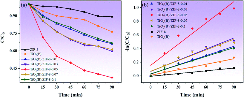 | ||
| Fig. 9 Photocatalytic degradation of TC under visible light (a), plot of −ln(C/C0) versus irradiation time for the degradation of TC (b). | ||
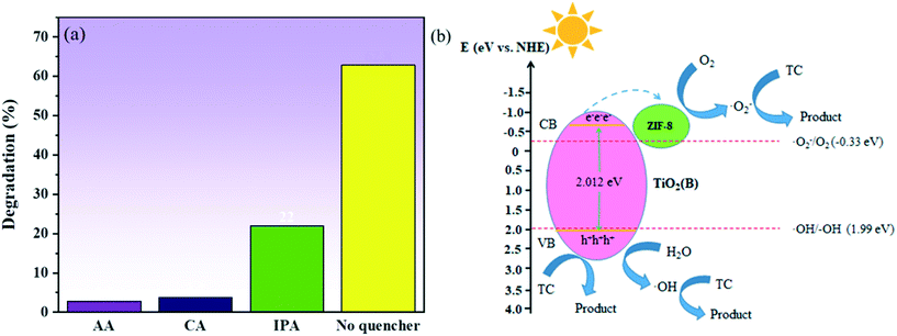
In order to study the role of holes (h+), hydroxyl radical (˙OH) and superoxide radicals (O2˙−) in the degradation of the pollutants, a series of free radical scavenging experiments were performed, and the results are shown in Fig. 10a. The degradation of TC was observed to be significantly inhibited in the presence of AA and CA, and the degradation of TC was also found to be affected in the presence of IPA. These results indicated that the role of holes (h+) and superoxide radical (O2˙−) was critical in the degradation of TC, with the hydroxyl group (˙OH) playing a supporting role. In order to determine the energy band structure of TiO2(B)/ZIF-8 in a better way, the flat band potential of TiO2(B) was measured using a Mott–Schottky plot. As can be seen from Fig. S2,† TiO2(B) is a typical n-type semiconductor, and the flat band potential of TiO2(B) is −0.8 V (vs. SCE), thus the standard hydrogen electrode is −0.558 V (vs. NHE) via calculate.42 According to previous studies, it can be concluded that the conduction band (CB) of the n-type semiconductor is 0.1–0.3 eV lower than of the flat band potential.43,44 Therefore, the conduction band position of TiO2(B) was −0.658 eV, and the valence band position was calculated to be 2.012 eV according to the band gap diagram of Fig. 5. According to the conduction band and valence band positions of TiO2(B), the band structure of TiO2(B) was obtained and a possible photocatalytic route was proposed. As can be seen from Fig. 10b, the electrons and holes are generated on TiO2(B) under excitation by light. In addition, the electrons are transferred from the conduction band of TiO2(B) to ZIF-8, and then O2 was electronically oxidized to superoxide radicals (O2˙−) to decompose TC. Simultaneously, the holes (h+) not only decompose TC but also oxidize water to hydroxyl groups (˙OH) to decompose TC, which was consistent with the results of the capture experiments.
4. Conclusions
In summary, the TiO2(B)/ZIF-8 composite was synthesized via a simple method. Through various characterization techniques, it was concluded that the narrow band gap of the composite was due to the increased oxygen vacancies and the introduction of Ti3+ species. Compared to that of bare TiO2(B) and ZIF-8, the degradation effect of the TiO2(B)/ZIF-8-0.05 composite increased by 8 and 3.6 times, respectively. These results provide important clues for the semiconductor modification and coupling with metal–organic frameworks, which need to be continuously developed and applied in practice.Conflicts of interest
There are no conflicts to declare.Acknowledgements
The authors thank the financial support from Program for the Development of Science and Technology of Jilin Province (No. 20170204038GX).References
- B. Bajorowicz, M. P. Kobylanski, A. Golabiewska, J. Nadolna, A. Zaleska-Medynska and A. Malankowska, Quantum dot-decorated semiconductor micro- and nanoparticles: A review of their synthesis, characterization and application in photocatalysis, Adv. Colloid Interface Sci., 2018, 256, 352–372 CrossRef CAS PubMed
.
- Y. Xu, C. Zhang, P. Lu, X. Zhang, L. Zhang and J. Shi, Overcoming poisoning effects of heavy metal ions against photocatalysis for synergetic photo-hydrogen generation from wastewater, Nano Energy, 2017, 38, 494–503 CrossRef CAS
.
- L. Shen, Z. Xing, J. Zou, Z. Li, X. Wu, Y. Zhang, Q. Zhu, S. Yang and W. Zhou, Black TiO2 nanobelts/g-C3N4 nanosheets Laminated Heterojunctions with Efficient Visible-Light-Driven Photocatalytic Performance, Sci. Rep., 2017, 7, 41978 CrossRef CAS PubMed
.
- J. Becker, K. R. Raghupathi, J. St. Pierre, D. Zhao and R. T. Koodali, Tuning of the Crystallite and Particle Sizes of ZnO Nanocrystalline Materials in Solvothermal Synthesis and Their Photocatalytic Activity for Dye Degradation, J. Phys. Chem. C, 2011, 115(28), 13844–13850 CrossRef CAS
.
- R. Zhang, B. Du, Q. Li, Z. Cao, G. Feng and X. Wang, α-Fe2O3 nanoclusters confined into UiO-66 for efficient visible-light photodegradation performance, Appl. Surf. Sci., 2019, 466, 956–963 CrossRef CAS
.
- O. Sacco, V. Vaiano, D. Sannino, R. A. Picca and N. Cioffi, Ag modified ZnS for photocatalytic water pollutants degradation: Influence of metal loading and preparation method, J. Colloid Interface Sci., 2019, 537, 671–681 CrossRef CAS PubMed
.
- R. Bera, S. Kundu and A. Patra, 2D Hybrid Nanostructure of Reduced Graphene Oxide–CdS Nanosheet for Enhanced Photocatalysis, ACS Appl. Mater. Interfaces, 2015, 7(24), 13251–13259 CrossRef CAS PubMed
.
- Q. Li, F. Wang, L. Sun, Z. Jiang, T. Ye, M. Chen, Q. Bai, C. Wang and X. Han, Design and Synthesis of Cu@CuS Yolk–Shell Structures with Enhanced Photocatalytic Activity, Nano-Micro Lett., 2017, 9(3), 35 CrossRef PubMed
.
- J. Fu, J. Yu, C. Jiang and B. Cheng, g-C3N4-Based Heterostructured Photocatalysts, Adv. Energy Mater., 2018, 8(3), 1701503 CrossRef
.
- N. F. F. Moreira, M. J. Sampaio, A. R. Ribeiro, C. G. Silva, J. L. Faria and A. M. T. Silva, Metal-free g-C3N4 photocatalysis of organic micropollutants in urban wastewater under visible light, Appl. Catal., B, 2019, 248, 184–192 CrossRef CAS
.
- B. Paik, M. Tsubota, T. Ichikawa and Y. Kojima, Catalytic effect of ATiO3 (A = Sr, Ba) on ammonia decomposition during mechanical milling, Chem. Commun., 2010, 46(22), 3982–3984 RSC
.
- M. Wu, K. Fu, H. Deng and J. Shi, Cobalt tetracarboxyl phthalocyanine-manganese octahedral molecular sieve (OMS-2) as a heterogeneous catalyst of peroxymonosulfate for degradation of diclofenac, Chemosphere, 2019, 219, 756–765 CrossRef CAS PubMed
.
- S. Sharma, V. Dutta, P. Singh, P. Raizada, A. Rahmani-Sani, A. Hosseini-Bandegharaei and V. K. Thakur, Carbon quantum dot supported semiconductor photocatalysts for efficient degradation of organic pollutants in water: A review, J. Cleaner Prod., 2019, 228, 755–769 CrossRef CAS
.
- M. Zhang, Q. Shang, Y. Wan, Q. Cheng, G. Liao and Z. Pan, Self-template synthesis of double-shell TiO2@ZIF-8 hollow nanospheres via sonocrystallization with enhanced photocatalytic activities in hydrogen generation, Appl. Catal., B, 2019, 241, 149–158 CrossRef CAS
.
- X. Wang, R. Xia, E. Muhire, S. Jiang, X. Huo and M. Gao, Highly enhanced photocatalytic performance of TiO2 nanosheets through constructing TiO2/TiO2 quantum dots
homojunction, Appl. Surf. Sci., 2018, 459, 9–15 CrossRef CAS
.
- A. S. Weber, A. M. Grady and R. T. Koodali, Lanthanide modified semiconductor photocatalysts, Catal. Sci. Technol., 2012, 2(4), 683–693 RSC
.
- X. Sun, J. Lin, H. Guan, L. Li, L. Sun, Y. Wang, S. Miao, Y. Su and X. Wang, Complete oxidation of formaldehyde over TiO2 supported subnanometer Rh catalyst at ambient temperature, Appl. Catal., B, 2018, 226, 575–584 CrossRef CAS
.
- H. H. Mohamed and A. A. Alsanea, TiO2/carbon dots decorated reduced graphene oxide composites from waste car bumper and TiO2 nanoparticles for photocatalytic applications, Arabian J. Chem., 2020, 13, 3082–3091 CrossRef CAS
.
- A. Giampiccolo, D. M. Tobaldi, S. G. Leonardi, B. J. Murdoch, M. P. Seabra, M. P. Ansell, G. Neri and R. J. Ball, Sol gel graphene/TiO2 nanoparticles for the photocatalytic-assisted sensing and abatement of NO2, Appl. Catal., B, 2019, 243, 183–194 CrossRef CAS
.
- J. Ye, J. He, S. Wang, X. Zhou, Y. Zhang, G. Liu and Y. Yang, Nickel-loaded black TiO2 with inverse opal structure for photocatalytic reduction of CO2 under visible light, Sep. Purif. Technol., 2019, 220, 8–15 CrossRef CAS
.
- Y. Pi, X. Li, Q. Xia, J. Wu, Y. Li, J. Xiao and Z. Li, Adsorptive and photocatalytic removal of Persistent Organic Pollutants (POPs) in water by metal-organic frameworks (MOFs), Chem. Eng. J., 2018, 337, 351–371 CrossRef CAS
.
- X. Gong, R. Zhao, J. Qin, H. Wang and D. Wang, Ultra-efficient removal of NO in a MOFs-NTP synergistic process at ambient temperature, Chem. Eng. J., 2019, 358, 291–298 CrossRef CAS
.
- Y. Gao, J. Xia, D. Liu, R. Kang, G. Yu and S. Deng, Synthesis of mixed-linker Zr-MOFs for emerging contaminant adsorption and photodegradation under visible light, Chem. Eng. J., 2019, 378, 122118 CrossRef CAS
.
- S. Li, P. Luo, H. Wu, C. Wei, Y. Hu and G. Qiu, Strategies for Improving the Performance and Application of MOFs Photocatalysts, ChemCatChem, 2019, 11(13), 2978–2993 CrossRef CAS
.
- D. Sun, P. R. Adiyala, S. J. Yim and D. P. Kim, Pore-Surface Engineering by Decorating Metal-Oxo Nodes with Phenylsilane to Give Versatile Super-Hydrophobic Metal-Organic Frameworks (MOFs), Angew. Chem., Int. Ed., 2019, 58(22), 7405–7409 CrossRef CAS PubMed
.
- C. V. Reddy, K. R. Reddy, V. V. N. Harish, J. Shim, M. V. Shankar, N. P. Shetti and T. M. Aminabhavi, Metal-organic frameworks (MOFs)-based efficient heterogeneous photocatalysts: Synthesis, properties and its applications in photocatalytic hydrogen generation, CO2 reduction and photodegradation of organic dyes, Int. J. Hydrogen Energy, 2020, 45, 7656–7679 CrossRef CAS
.
- X. Deng, Z. Li and H. Garcia, Visible Light Induced Organic Transformations Using Metal-Organic-Frameworks (MOFs), Chemistry, 2017, 23(47), 11189–11209 CrossRef CAS PubMed
.
- Z. Lei, Y. Xue, W. Chen, W. Qiu, Y. Zhang, S. Horike and L. Tang, MOFs-Based Heterogeneous Catalysts: New Opportunities for Energy-Related CO2 Conversion, Adv. Energy Mater., 2018, 8(32), 1801587 CrossRef
.
- Y. Tang, D. Dubbeldam, X. Guo, G. Rothenberg and S. Tanase, Efficient Separation of Ethanol-Methanol and Ethanol-Water Mixtures Using ZIF-8 Supported on a Hierarchical Porous Mixed-Oxide Substrate, ACS Appl. Mater. Interfaces, 2019, 11(23), 21126–21136 CrossRef CAS PubMed
.
- L. Zhou, N. Li, G. Owens and Z. Chen, Simultaneous removal of mixed contaminants, copper and norfloxacin, from aqueous solution by ZIF-8, Chem. Eng. J., 2019, 362, 628–637 CrossRef CAS
.
- Q. Li, W. Yang, F. Li, A. Cui and J. Hong, Preparation of CoB/ZIF-8 supported catalyst by single step reduction and its activity in hydrogen production, Int. J. Hydrogen Energy, 2018, 43(1), 271–282 CrossRef CAS
.
- E. Pipelzadeh, V. Rudolph, G. Hanson, C. Noble and L. Wang, Photoreduction of CO2 on ZIF-8/TiO2 nanocomposites in a gaseous photoreactor under pressure swing, Appl. Catal., B, 2017, 218, 672–678 CrossRef CAS
.
- X. Chen, L. Liu, P. Y. Yu and S. S. Mao, Increasing Solar Absorption for Photocatalysis with Black Hydrogenated Titanium Dioxide Nanocrystals, Science, 2011, 331, 746–750 CrossRef CAS PubMed
.
- G. Rajender, J. Kumar and P. K. Giri, Interfacial charge transfer in oxygen deficient TiO2-graphene quantum dot hybrid and its influence on the enhanced visible light photocatalysis, Appl. Catal., B, 2018, 224, 960–972 CrossRef CAS
.
- A. Balati, S. Tek, K. Nash and H. Shipley, Nanoarchitecture of TiO2 microspheres with expanded lattice interlayers and its heterojunction to the laser modified black TiO2 using pulsed laser ablation in liquid with improved photocatalytic performance under visible light irradiation, J. Colloid Interface Sci., 2019, 541, 234–248 CrossRef CAS PubMed
.
- W. F. Zhang, Y. L. He, M. S. Zhang, Z. Yin and Q. Chen, Raman scattering study on anatase TiO2nanocrystals, J. Phys. D: Appl. Phys., 2000, 33(8), 912–916 CrossRef CAS
.
- B. Santara, P. K. Giri, K. Imakita and M. Fujii, Evidence of oxygen vacancy induced room temperature ferromagnetism in solvothermally synthesized undoped TiO2 nanoribbons, Nanoscale, 2013, 5(12), 5476–5488 RSC
.
- S. Umrao, S. Abraham, F. Theil, S. Pandey, V. Ciobota, P. K. Shukla, C. J. Rupp, S. Chakraborty, R. Ahuja, J. Popp, B. Dietzek and A. Srivastava, A possible mechanism for the emergence of an additional band gap due to a Ti–O–C bond in the TiO2–graphene hybrid system for enhanced photodegradation of methylene blue under visible light, RSC Adv., 2014, 4(104), 59890–59901 RSC
.
- Z.-W. Wu, S.-L. Tyan, H.-H. Chen, J.-C.-A. Huang, Y.-C. Huang, C.-R. Lee and T.-S. Mo, Temperature-dependent photoluminescence and XPS study of ZnO nanowires grown on flexible Zn foil via thermal oxidation, Superlattices Microstruct., 2017, 107, 38–43 CrossRef CAS
.
- W. Fang, M. Xing and J. Zhang, A new approach to prepare Ti3+ self-doped TiO2 via NaBH4 reduction and hydrochloric acid treatment, Appl. Catal., B, 2014, 160–161, 240–246 CrossRef CAS
.
- C. Li, Q. Han, Y. Pan, J. Zhao, Y. Luo and P. Na, Insights into the photosensitization activity of zirconium-titanium pyrophosphate under visible light irradiation, Mater. Lett., 2020, 268, 127399 CrossRef CAS
.
- W. Shi, F. Guo, H. Wang, M. Han, H. Li, S. Yuan, H. Huang, Y. Liu and Z. Kang, Carbon dots decorated the exposing high-reactive (111) facets CoO octahedrons with enhanced photocatalytic activity and stability for tetracycline degradation under visible light irradiation, Appl. Catal., B, 2017, 219, 36–44 CrossRef CAS
.
- J. Zheng and L. Zhang, Designing 3D magnetic peony flower-like cobalt oxides/g-C3N4 dual Z-scheme photocatalyst for remarkably enhanced sunlight driven photocatalytic redox activity, Chem. Eng. J., 2019, 369, 947–956 CrossRef CAS
.
- Y. Matsumoto, Energy Positions of Oxide Semiconductors and Photocatalysis with Iron Complex Oxides, J. Solid State Chem., 1996, 126(2), 227–234 CrossRef CAS
.
Footnote |
| † Electronic supplementary information (ESI) available. See DOI: 10.1039/d0ce00595a |
| This journal is © The Royal Society of Chemistry 2020 |

