 Open Access Article
Construction of in situ self-assembled FeWO4/g-C3N4 nanosheet heterostructured Z-scheme photocatalysts for enhanced photocatalytic degradation of rhodamine B and tetracycline†
Ramakrishna
Dadigala
 a,
RajKumar
Bandi
 a,
Bhagavanth Reddy
Gangapuram
ab and
Veerabhadram
Guttena
 *a
*a
aDepartment of Chemistry, Osmania University, Hyderabad, Telangana State 500007, India
bDepartment of Chemistry, PG Center Wanaparthy, Palamuru University, Mahabub Nagar, Telangana State 509001, India. E-mail: gvbhadram@gmail.com
First published on 4th September 2018
Abstract
Although photocatalytic degradation is an ideal strategy for cleaning environmental pollution, it remains challenging to construct a highly efficient photocatalytic system by steering the charge flow in a precise manner. In this work, a novel, highly efficient, stable, and visible light active hybrid photocatalytic system consisting of FeWO4 and g-C3N4 nanosheets (CNNs) has been successfully prepared by an in situ self-assembly solvothermal approach. Several characterization techniques were employed to study the phase structures, morphologies, optical properties, surface composition and chemical state of the as-prepared samples. SEM and TEM results demonstrated that the FeWO4 nanoparticles are uniformly dispersed on the surface of CNNs with a diameter of about 10–20 nm, which could provide maximum interfacial contact and a synergistic coupling effect between FeWO4 and CNNs. XPS and FTIR results confirmed that there was strong electrostatic interaction between FeWO4 and CNNs, suggesting the formation of heterojunctions between them. In addition, UV-DRS and PL spectroscopy revealed that the FeWO4/CNN composites exhibited increased visible light absorption and improved charge generation/separation efficiency. As a result, the photocatalytic activity of the FeWO4/CNNs was enhanced in comparison with pure FeWO4 and CNNs for rhodamine B (RhB) and tetracycline (TC) degradation under natural sunlight irradiation. The photocatalytic efficiency of the optimal FeWO4/CNN composite (10 wt% FeWO4/CNNs) for the degradation of RhB (TC) was about 13.26 (4.95) and 86.2 (31.1) times higher than that of pure FeWO4 and CNNs, respectively. Meanwhile, the 10 wt% FeWO4/CNN sample exhibits good photocatalytic stability in recycling experiments. The enhanced photocatalytic activity may be attributed to the formation of the Z-scheme system between FeWO4 and CNNs, effectively prolonging the lifetime of the photoexcited electrons generated by CNNs and the photoexcited holes generated by FeWO4, which was subsequently confirmed by the active species trapping experiments and the calculation of relative band alignments. This work opens up a new feasible avenue to synthesize visible light active Z-scheme photocatalysts for application in energy production and environmental remediation.
1. Introduction
Over the past few decades, environmental pollution has become one of the greatest problems to society. The effluents produced by many industries, such as textile, pharmaceutical, cosmetic, leather, and food industries, are identified as the primary source of water contamination, which is harmful to the environment, and hazardous to human health as well as ecosystems.1–3 Due to their stable chemical structures and recalcitrance to biological degradation, conventional wastewater treatment processes are not always efficient in the removal of these pollutants.4–6 As a result, they have been frequently detected in a variety of environmental matrices, including surface, ground and potable water, soils and even the food on our table. There is therefore a need for the development of efficient treatment technologies for the removal of these compounds from wastewater. A “green” photocatalytic strategy that utilizes solar energy has been considered as a sustainable solution to solve the above-mentioned problems.7–12 Nevertheless, the photocatalytic performance of most semiconductor photocatalysts available is located at a low level, and their practical application is hampered by some internal effects, such as poor visible light utilization, lower photogenerated electron–hole pair separation, and the lack of active species generation.13–15 Thus, to maximize the utilization of solar light, the development of visible light active photocatalysts with sufficient charge separation ability and high photocatalytic stability is still an arduous task in photocatalysis research. Hence, the fabrication of heterojunctions is an effective and attractive strategy to restrain the recombination rate of photogenerated charge carriers.16–18 Nevertheless, it is difficult to simultaneously achieve high charge separation efficiency and strong redox ability. Recently, the construction of artificial Z-scheme photocatalytic systems has emerged as an alternative method, because it can not only separate the photogenerated electron–hole pairs but also maintain the excellent redox capacity of the constituent semiconductors.19–21 However, the majority of the synthesized artificial Z-scheme photocatalytic systems usually had mediators (e.g. redox pairs (Fe3+/Fe2+ and IO3−/I−))22,23 and noble metals (Ag and Au),24,25 which will bring about great difficulties in their practical application.19 Thus, developing a mediator-free direct Z-scheme photocatalytic system as an ideal and effective method has become a hotspot for application in environmental purification and hydrogen generation from water.26–31Recently, two-dimensional (2D) materials have been widely studied in photocatalysis due to their unique structural and optical properties, of which the g-C3N4 material gained special attention because it is abundant, sustainable, environmentally friendly and has a suitable band gap and high chemical stability, making it potentially suitable for solar energy conversion and environmental purification.32–36 Unfortunately, pure g-C3N4 seriously suffers from poor photocatalytic efficiency because of a high recombination rate of photogenerated charge carriers.37–40 Besides, it is reported that g-C3N4 nanosheets show considerably superior photocatalytic activity compared to the bulk g-C3N4 resulting from the reduction of internal defects and improvement of the specific surface area.41,42 It can be predicted that the photocatalytic activity of g-C3N4-based photocatalysts may be further enhanced by increasing the specific surface area of bulk g-C3N4. Thus, it is accepted that the construction of g-C3N4-based Z-scheme photocatalysts with a narrow band gap semiconductor may provide bright prospects for dealing with the increasingly serious environmental pollution.
Recent studies have investigated some metal tungstates as potential co-catalyst candidates for photocatalytic applications, which could effectively reduce the recombination of charge carriers for improving the degradation of pollutants.43–45 Among these tungstates, the investigation of iron tungstate (FeWO4) has been widely reported in the literature due to its narrow band gap, and good magnetic and photocatalytic properties.46,47 Recently, FeWO4 has been explored for photocatalytic reactions with no co-catalysts.48,49 Furthermore, suitable matching of the band levels of FeWO4 with g-C3N4 nanosheets to form a direct Z-scheme photocatalytic system offers appropriate driving forces to separate and transfer photogenerated electron–hole pairs. As FeWO4 and g-C3N4 are both visible light driven photocatalysts, after combining the FeWO4 photocatalyst with g-C3N4 nanosheets, the obtained FeWO4/g-C3N4 nanosheet composite may be a promising candidate for efficient photocatalytic activity under visible light irradiation. However, to the best of our knowledge, no group has reported in situ growth of FeWO4 nanoparticles on the surface of g-C3N4 nanosheets by a facile solvothermal method for the degradation of RhB and TC under sunlight irradiation.
Based on the above considerations, herein we grew FeWO4 nanoparticles on the surface of g-C3N4 nanosheets by a facile solvothermal method to form composite catalysts for efficient degradation of organic pollutants and these composites were found to exhibit superior photocatalytic activity compared with the pure FeWO4, g-C3N4 nanosheets and mechanically mixed catalyst. It was found that the composite photocatalysts exhibited not only an improved photocatalytic activity but also excellent stability and reusability during the photocatalytic process, which can be mainly attributed to the synergistic effect between FeWO4 and g-C3N4 nanosheets. Furthermore, a possible direct Z-scheme mechanism for the enhanced photocatalytic activity of the FeWO4/g-C3N4 nanosheet composite was also discussed based on the relative band gap positions of these two semiconductors and the free radical trapping experimental results. Detailed characterization of the structure, composition, and optical properties of the as-prepared photocatalysts was also carried out.
2. Experimental section
2.1. Preparation of bulk g-C3N4 and g-C3N4 nanosheets
Bulk g-C3N4 (CN) was prepared by thermal polymerization of melamine at high temperature in a muffle furnace.50 In detail, 5 g of melamine was placed in a crucible with a cover, and then, it was heated at 600 °C for 2 h with a ramp rate of about 3 °C min−1. After cooling to room temperature, the obtained yellow agglomerates were collected and ground into fine powder. After that, g-C3N4 nanosheets (CNNs) were prepared by using the liquid exfoliation method.50 In detail, 100 mg of the as-prepared CN was dispersed in 100 mL of double distilled water, then the mixture was sonicated for 16 h and then the resulting suspension was centrifuged at 5000 rpm to remove the residual un-exfoliated g-C3N4. Then, the final suspension was dried at 80 °C overnight.2.2. Preparation of FeWO4/g-C3N4 nanosheet composites
FeWO4/CNN composites were synthesized through a solvothermal method.47,51 First, an appropriate amount of the as-prepared CNNs was dispersed in 36 mL of ethylene glycol by sonication for 30 min, to facilitate the uniform growth of FeWO4 nanoparticles on their surface. Then, 5 mmol of FeCl3·6H2O dissolved in 2 mL double distilled water was added to the CNN suspension and stirred magnetically for 30 min. Subsequently, 5 mmol of Na2WO4·2H2O dissolved in 2 mL of double distilled water was added dropwise to the above mixture. 10 mmol of sodium acetate was then added to the above mixture with continuous stirring. After 30 min of stirring, the above suspension was transferred into a Teflon-lined stainless steel autoclave (50 mL) and reacted at 200 °C for 12 h. After cooling down to room temperature naturally, the products obtained were collected by centrifugation, washed several times with double distilled water and ethanol, and dried in an oven at 80 °C for 12 h. The as-prepared FeWO4/CNN composites with various FeWO4 amounts of 5, 10, 15 and 20 wt% were denoted as 5-FWO/CNNs, 10-FWO/CNNs, 15-FWO/CNNs and 20-FWO/CNNs, respectively. Pure FeWO4 nanoparticles were also synthesized under the same conditions without adding any CNN powder.In addition, a control sample was also prepared by mechanical grinding of CNNs and FeWO4. A mixture of FeWO4 and CNNs was finely ground and then calcined at 200 °C for 12 h. After cooling to room temperature, the resultant product was collected and crushed to powder for further use. The mass ratio of FeWO4 and CNNs in the sample was the same as that in the optimal composite catalyst of FeWO4/CNNs [10-FWO/CNNs]. The control sample was denoted as FeWO4 + CNNs. More details about the materials and characterization methods are provided in the ESI.†
2.3. Measurement of photocatalytic activity
The photocatalytic activities of the as-prepared photocatalysts were evaluated by the degradation of rhodamine B (RhB) and tetracycline (TC) under natural sunlight irradiation. All of the photocatalytic experiments were carried out during the same time on sunny days and the sunlight intensity was found to be around 100![[thin space (1/6-em)]](https://www.rsc.org/images/entities/char_2009.gif) 000 lx to 110
000 lx to 110![[thin space (1/6-em)]](https://www.rsc.org/images/entities/char_2009.gif) 000 lx. In a typical experiment, 50 mg of photocatalyst was suspended in an aqueous solution of RhB (50 mL, 10 mg L−1) and TC (50 mL, 20 mg L−1), and then the suspensions were stirred in the dark for 1 h to reach the adsorption–desorption equilibrium between the photocatalyst and model pollutants, after which the reaction suspension was irradiated for 90 min. At certain time intervals, 4 mL aliquots were sampled and centrifuged to remove the photocatalyst, and the concentrations of the remnant RhB and TC were analyzed by recording the absorbance using an UV-Vis spectrophotometer (UV-2600, Shimadzu). A blank test was also carried out without any photocatalyst under sunlight irradiation to evaluate the efficiency of the photocatalyst. Furthermore, the reusability of 10-FWO/CNNs was tested by four consecutive cycles for the degradation of RhB. After each cycle, the catalyst was separated from the reaction mixture by centrifugation and washed with double distilled water and dried overnight in an oven at 80 °C for use in the next cycle.
000 lx. In a typical experiment, 50 mg of photocatalyst was suspended in an aqueous solution of RhB (50 mL, 10 mg L−1) and TC (50 mL, 20 mg L−1), and then the suspensions were stirred in the dark for 1 h to reach the adsorption–desorption equilibrium between the photocatalyst and model pollutants, after which the reaction suspension was irradiated for 90 min. At certain time intervals, 4 mL aliquots were sampled and centrifuged to remove the photocatalyst, and the concentrations of the remnant RhB and TC were analyzed by recording the absorbance using an UV-Vis spectrophotometer (UV-2600, Shimadzu). A blank test was also carried out without any photocatalyst under sunlight irradiation to evaluate the efficiency of the photocatalyst. Furthermore, the reusability of 10-FWO/CNNs was tested by four consecutive cycles for the degradation of RhB. After each cycle, the catalyst was separated from the reaction mixture by centrifugation and washed with double distilled water and dried overnight in an oven at 80 °C for use in the next cycle.
2.4. Analysis of reactive species
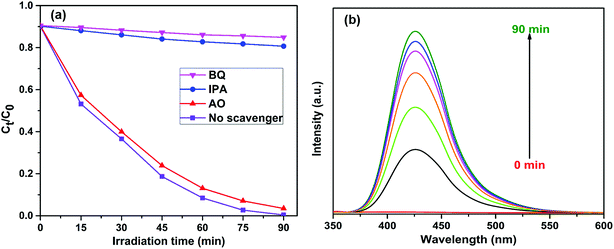
To investigate the active species generated during the photodegradation process, ammonium oxalate (AO, 1 mM), iso-propanol (IPA, 1 mM), and 1,4-benzoquinone (BQ, 1 mM) were used as the hole (h+), hydroxyl radical (˙OH), and superoxide radical (˙O2−) scavengers,50 respectively. The method was similar to the above photocatalytic activity test. The ˙OH content was also measured by the PL technique, using terephthalic acid (TA) as a probe molecule.523. Results and discussion
A facile in situ solvothermal method was designed for the preparation of FeWO4/g-C3N4 nanosheet photocatalysts, and the preparation process is illustrated in Scheme 1. Firstly, the g-C3N4 nanosheets obtained from the bulk g-C3N4 through a liquid exfoliation method were dispersed in ethylene glycol by sonication. Then, upon addition of FeCl3 solution to the above reaction mixture, the Fe3+ ions were reduced to Fe2+ ions because of the reducing ability of ethylene glycol. Then, with the addition of NaWO4 solution and sodium acetate (here sodium acetate provided an alkaline environment), the Fe2+ ions reacted with WO42− ions to generate FeWO4 nuclei on the g-C3N4 nanosheet surface under constant stirring. As the solvothermal treatment time increased, the FeWO4 nuclei grew into nanoparticles through a self-assembly growth mechanism.47 In this case, g-C3N4 nanosheets not only act as the support to form heterostructures but are also employed as dispersants to hinder the aggregation of FeWO4 nanoparticles. Finally, FeWO4/CNN heterostructured photocatalysts were obtained.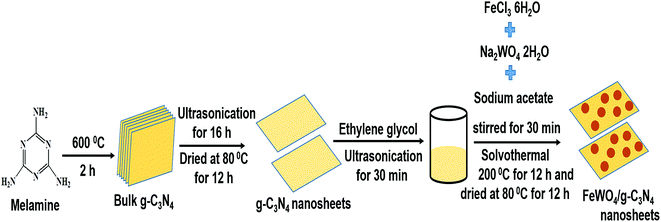 | ||
| Scheme 1 Schematic representation of the preparation of bulk g-C3N4, g-C3N4 nanosheets and FeWO4/g-C3N4 nanosheet composites. | ||
3.1. Characterization of photocatalysts
The crystalline phases of the as-prepared samples were examined by XRD analysis. Fig. 1a shows the XRD patterns of the CN, CNNs, FeWO4 and FeWO4/CNN composites. The pure CN has two significant peaks at 27.4° and 13.1°, indexed to the (002) and (100) diffraction planes of g-C3N4, corresponding to the characteristic inter-layer stacking of aromatic systems and the in-plane structural packing motif of tri-s-triazine units,53–55 respectively. Interestingly, in the case of CNNs, the intensity of diffraction peaks significantly decreased, indicating that the CNN structure has been successfully obtained after exfoliation.56 Besides, the dominant (002) peak in CNNs shifted slightly to a higher angle (Fig. 1b), which may be due to the decreased distance between the layers and which is in good agreement with previous reports.57 For pure FeWO4, the positions of all peaks can be well indexed to the monoclinic phase of FeWO4 (JCPDS card no. 46-1446).51 It can also be found that the diffraction peaks of FeWO4/CNN composites consisted of the characteristic peaks of FeWO4 and CNNs, which implied the coexistence of FeWO4 and CNN phases in the as-prepared FeWO4/CNN composites. As the FeWO4 concentration increases from 5 to 20 wt%, the diffraction peaks of FeWO4 gradually intensify, whereas the peaks of CNNs are weakened and no phase structural changes have been detected, suggesting that the introduction of FeWO4 did not change the phase structure of g-C3N4 during the in situ growth process. The above results confirm that the FeWO4/CNN composites are successfully constructed.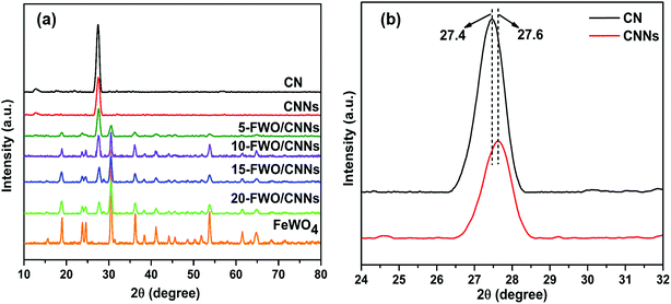 | ||
| Fig. 1 (a) XRD patterns of CN, CNNs, FeWO4 and the FeWO4/CNNs composites and (b) magnified curves of CN and CNNs. | ||
The morphology and microstructure of the as-prepared samples were investigated by SEM and TEM. Fig. 2a–d show the SEM images of CN, CNNs, FeWO4 and the 10-FWO/CNNs composite, respectively. As shown in Fig. 2a, the pure CN has a layered structure composed of tightly stacked g-C3N4 nanosheets several micrometers in size. And as expected, after exfoliation, the CNNs (Fig. 2b) exhibited a clear two-dimensional sheet-like structure with wrinkled edges, which further confirmed the successful exfoliation of CN.50 Furthermore, the thickness of CNNs decreases dramatically, which may result in an increase in the specific surface area and reactive species.57 From Fig. 2c, it can be seen that pure FeWO4 exhibited spherical shapes with a diameter of 10–20 nm. In the case of the 10-FWO/CNN composite (Fig. 2d), we can clearly see that numerous FeWO4 nanoparticles are well dispersed on the surface of CNNs. The EDS spectrum analysis of the 10-FWO/CNN composite (Fig. 2e) reveals that it contains of C, N, Fe, W, and O elements, which further confirmed the coexistence of CNN and FeWO4 phases in the FeWO4/CNN composites.
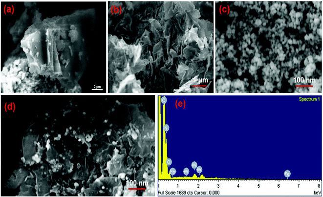 | ||
| Fig. 2 SEM images of (a) CN, (b) CNNs, (c) FeWO4 and (d) the 10-FWO/CNNs composite; and (e) the corresponding EDS image of the 10-FWO/CNN composite. | ||
TEM was also performed to further confirm the morphology of CNNs and the FeWO4/CNN composite formed. The TEM image shown in Fig. 3a further proved that the CNNs have a lamellar structure, with several stacking layers. The TEM image of 10-FWO/CNNs in Fig. 3b demonstrates that the FeWO4 nanoparticles are uniformly dispersed on the surface of CNNs with a diameter of about 10–20 nm, which is in good agreement with the SEM results. Given the different morphologies of FeWO4 and CNNs, the dark parts in the TEM image should be FeWO4, while the light parts correspond to CNNs. These highly dispersed FeWO4 nanoparticles could provide maximum interfacial contact with the CNN surface, which could further strengthen the synergistic coupling effect between FeWO4 and CNNs. Moreover, the intimate contact between FeWO4 and CNNs would further strengthen the photogenerated charge separation and transfer.58 To observe in detail the interface between FeWO4 and CNNs, HRTEM analysis was also performed. As shown in Fig. 3a and c, a lattice spacing of 0.326 nm that corresponds to the (002) crystallographic plane of g-C3N4 (ref. 38 and 59) and a clear lattice fringe of 0.37 nm ascribed to the (002) planes of FeWO4 (ref. 51) were observed, which confirms the formation of heterojunctions via the in situ growth of FeWO4 on the CNN surface. The formed interface is favorable for the transport of photogenerated charge carriers, and thereby promotes the separation of electron–hole pairs.
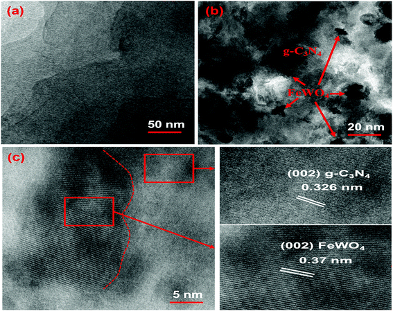 | ||
| Fig. 3 TEM images of the (a) CNNs and (b) 10-FWO/CNN composite; and (c) HRTEM image of the 10-FWO/CNN composite. | ||
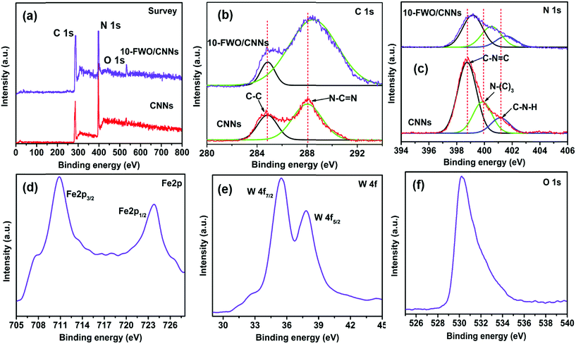
XPS analysis was performed to investigate the surface chemical states and bonding configuration of the pure CNNs and 10-FWO/CNN composite and the results (survey and high resolution spectra) are shown in Fig. 4. The survey XPS spectrum (Fig. 4a) of the 10-FWO/CNN composite exhibited strong C 1s and N 1s peaks related to the g-C3N4 phase, together with Fe 2p, W 4f and O 1s peaks related to the FeWO4 phase without any contamination, and the survey XPS spectrum of CNNs contains C 1s, N 1s and O 1s peaks. In addition, the small peak of O 1s in CNNs is assigned to adsorbed oxygen species. Fig. 4b shows the high-resolution spectra of C 1s. Pure CNNs show two peaks at 284.6 eV and 288.1 eV, which can be assigned to the sp2 C–C bond and sp2 bonded carbon of N–C![[double bond, length as m-dash]](https://www.rsc.org/images/entities/char_e001.gif) N coordination present in the triazine rings of g-C3N4, respectively.43 The 10-FWO/CNN composite also displayed the two C 1s peaks. However, compared with pure CNNs, the binding energy of 10-FWO/CNNs at 288.1 eV was shifted to 288.4 eV, while the position of the peak at 284.6 remained unchanged. The N 1s spectrum of CNNs (Fig. 4c) was deconvoluted into three peaks at 398.8, 399.8 and 401.1 eV, which could be assigned to sp2 hybridized aromatic nitrogen atoms bonded to carbon atoms (C–N
N coordination present in the triazine rings of g-C3N4, respectively.43 The 10-FWO/CNN composite also displayed the two C 1s peaks. However, compared with pure CNNs, the binding energy of 10-FWO/CNNs at 288.1 eV was shifted to 288.4 eV, while the position of the peak at 284.6 remained unchanged. The N 1s spectrum of CNNs (Fig. 4c) was deconvoluted into three peaks at 398.8, 399.8 and 401.1 eV, which could be assigned to sp2 hybridized aromatic nitrogen atoms bonded to carbon atoms (C–N![[double bond, length as m-dash]](https://www.rsc.org/images/entities/char_e001.gif) C), tertiary nitrogen groups (N–(C)3), and uncondensed amino groups (C–N–H), respectively.43 The N 1s binding energies of CNNs shifted to 339.1, 400.4 and 401.5 eV for 10-FWO/CNNs, respectively. These results indicate that the carbon and nitrogen atoms present in CNNs formed the binding interaction with metal species of FeWO4. In Fig. 4d, the peaks at 710.4 and 723.9 eV are assigned to the binding energies of Fe 2p3/2 and 2p1/2 respectively, and are characteristic of Fe2+ in the FeWO4 material.51 The W 4f peaks at 35.5 and 37.8 eV in Fig. 4e correspond to the W 4f7/2 and W 4f5/2 binding energies of W6+ in FeWO4,60 respectively. The O 1s peak at 530.1 eV (Fig. 4f) corresponds to the FeWO4 oxygen atom.60 The shifting of C 1s and N 1s peaks and presence of Fe 2p, W 4f and O 1s peaks in the 10-FWO/CNN composite can be ascribed to the fact that FeWO4 hybridized with CNNs during the in situ growth process, also indicating that certain chemical interactions are possibly formed between them, as observed in TEM images.
C), tertiary nitrogen groups (N–(C)3), and uncondensed amino groups (C–N–H), respectively.43 The N 1s binding energies of CNNs shifted to 339.1, 400.4 and 401.5 eV for 10-FWO/CNNs, respectively. These results indicate that the carbon and nitrogen atoms present in CNNs formed the binding interaction with metal species of FeWO4. In Fig. 4d, the peaks at 710.4 and 723.9 eV are assigned to the binding energies of Fe 2p3/2 and 2p1/2 respectively, and are characteristic of Fe2+ in the FeWO4 material.51 The W 4f peaks at 35.5 and 37.8 eV in Fig. 4e correspond to the W 4f7/2 and W 4f5/2 binding energies of W6+ in FeWO4,60 respectively. The O 1s peak at 530.1 eV (Fig. 4f) corresponds to the FeWO4 oxygen atom.60 The shifting of C 1s and N 1s peaks and presence of Fe 2p, W 4f and O 1s peaks in the 10-FWO/CNN composite can be ascribed to the fact that FeWO4 hybridized with CNNs during the in situ growth process, also indicating that certain chemical interactions are possibly formed between them, as observed in TEM images.
The chemical structure and functional groups of the as-prepared samples were studied using FTIR spectra and the results are shown in Fig. 5a. For the FTIR spectrum of pure FeWO4, the absorption bands appearing at 834 and 877 cm−1 were due to the symmetrical vibrations of bridging oxygen atoms of Fe–O–W. The absorption band at 650–680 cm−1 can be due to the stretching mode of W–O in WO6 octahedra and the absorption band at 556 cm−1 is the characteristic stretching vibration of the Fe–O bond in hematite particles.43 In the FTIR spectrum of CN, the series of bands observed in the region of 1200–1650 cm−1 are ascribed to the stretching vibration of C–N heterocycles, while the broad band at 3000–3500 cm−1 is ascribed to the stretching vibration of N–H groups and surface adsorbed hydroxyl groups. In addition, the band at 810 cm−1 originates from a breathing mode of s-triazine units.28,54,61 It can be seen that the characteristic FTIR spectrum of CNNs is similar to that of CN, indicating that the g-C3N4 chemical structure has not been destroyed after the exfoliation process. Moreover, the FTIR spectra of the FeWO4/CNNs composites are similar to that of pure CNNs, and all the characteristic absorption bands of CNNs appear in the composites, suggesting that no structural change of CNNs occurs during the composite formation. After introducing FeWO4 into CNNs, the characteristic bands from the C–N heterocycles of CNNs appear as blue shifts (Fig. 5b), indicating that there might be some interactions between the C–N heterocycles of g-C3N4 and FeWO4. From the TEM, XPS and FTIR results, we concluded that there was strong electrostatic interaction between FeWO4 and CNNs, which could promote photogenerated electron–hole pair separation and transfer, and further enhance the photocatalytic performance of the FeWO4/CNN composites.
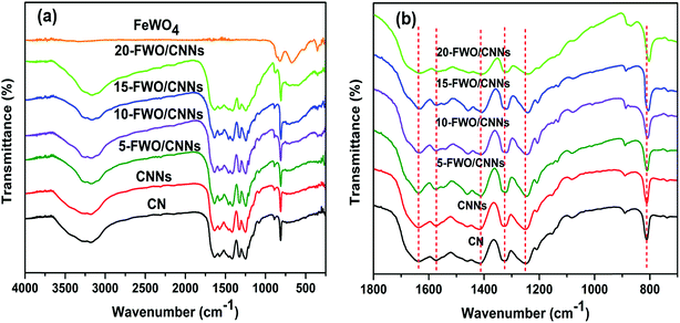 | ||
| Fig. 5 (a) FTIR spectra of CN, CNNs, FeWO4 and the FeWO4/CNN composites; and (b) magnified curves in the range of 700 to 1800 cm−1. | ||
The light absorption properties of the as-prepared samples were examined by UV-vis DRS analysis (Fig. 6). As shown in Fig. 6a, CNNs show a slight blue shift of the absorption edge with respect to that of CN, which is ascribed to the quantum confinement effect of g-C3N4 nanosheets and is consistent with previous reports.62 The pure FeWO4 exhibited profound absorption over a wide spectral region from UV to visible light. After the introduction of FeWO4 into CNNs, the composite samples exhibited stronger optical absorption in the visible region compared with CNNs, and the absorption intensities of these composites are strengthened with an increase in the FeWO4 content. This demonstrates well that the in situ grown FeWO4 nanoparticles can act as a sensitizer for enhancing the visible light absorption of CNNs, suggesting that the FeWO4/CNN composites can harvest more light energy and produce more photogenerated charge carriers.
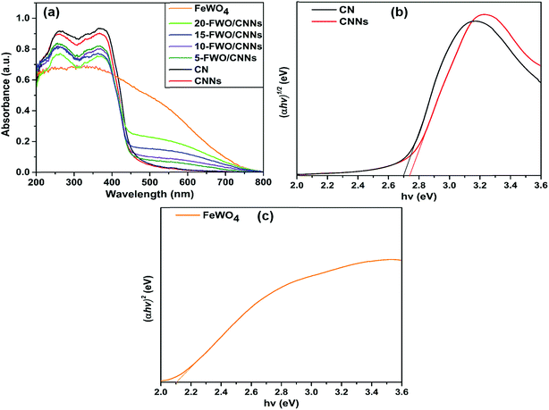 | ||
| Fig. 6 (a) UV-vis diffuse reflectance spectra of CN, CNNs, FeWO4 and the FeWO4/CNN composites; (b) (αhν)1/2versus hν plot of CNNs and CN; and (c) (αhν)2versus hν plot of FeWO4. | ||
The energy level and band gap of the semiconductors play a crucial role in determining their physical properties. The band gap energies of the as-prepared photocatalysts can be calculated using the following formula45
| αhν = A(hν − Eg)n/2 |
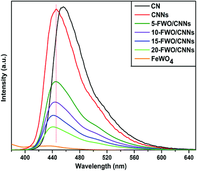
Generally, the PL spectra of photocatalysts can be used to illustrate the recombination rate of the photogenerated electron–hole pairs; it is known that higher PL intensity usually means more recombination of electron–hole pairs and lower photocatalytic activity. Fig. 7 shows the PL spectra of the as-prepared samples. It can be observed that both the CN and CNNs have a strong PL peak at an excitation wavelength of 360 nm, which could be related to the recombination of the photogenerated electron–hole pairs in g-C3N4. A blue shifted peak for CNNs compared with that for CN is mainly due to shifted conduction band and valence band edges, which is caused by the well-known quantum confinement effect.62 After coupling CNNs with FeWO4, the emission peak intensities decreased significantly, indicating that the recombination of electron–hole pairs is greatly suppressed by the introduction of FeWO4. One reason might be that coupling with FeWO4 may change the transition path of photogenerated electrons to the ground state for CNNs, which may result from interactions between CNNs and FeWO4. As a result, the charge separation could be promoted on the FeWO4/CNN composites, leading to the higher photocatalytic activity of the composite photocatalysts. From Fig. 7, it can also be seen that the PL peak positions shifted to lower wavelengths with the increase in the amount of FeWO4. This may be caused by the strong interaction between the FeWO4 and CNNs in the composite samples, which also occurred in the g-C3N4–WO3 system.59
3.2. Photocatalytic performance
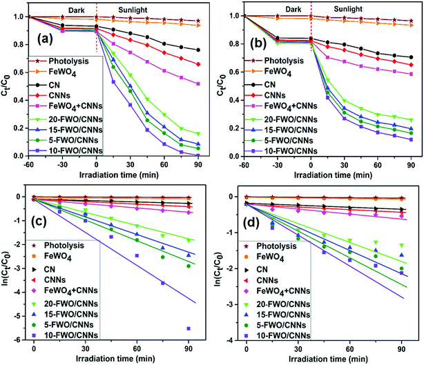
In order to investigate the photocatalytic activities of the as-prepared samples, RhB and TC were chosen as model pollutants for photocatalytic degradation (Fig. 8). Negligible self-degradation was observed for RhB and TC under sunlight irradiation for ∼90 min (Fig. 8a and b). As expected, all FeWO4/CNN composites exhibited higher photocatalytic activities than pure FeWO4, CN and CNNs with a hierarchical order of 10-FWO/CNNs > 5-FWO/CNNs > 15-FWO/CNNs > 20-FWO/CNNs, indicating that the FeWO4 content influenced the photocatalytic activity of the as-prepared composites notably. This could be explained by the effective separation of photogenerated electron–hole pairs due to the formation of heterojunctions between FeWO4 and CNNs in the composites. Moreover, the activities of the composite samples were found to increase with the increase in the FeWO4 content from 5 wt% (94.5% for RhB, 83.4% for TC) to 10 wt% (99.6% for RhB, 88% for TC), and then decrease with further increase in the FeWO4 content from 10 wt% to 20 wt% (83.9% for RhB, 73.9% for TC), suggesting that the FeWO4/CNN composites had the highest photocatalytic activity with the optimum FeWO4 content of 10 wt%. The reason for this may be that when the amount of FeWO4 is lower than its optimum amount, the trapping sites of carriers increase with the increase of the FeWO4 amount, which prolongs the lifetime of carriers, thus improving the photocatalytic activity. However, when the amount of FeWO4 is higher than its optimum amount, excessive FeWO4 (15 wt% and 20 wt%) may be clustered and effective heterojunction photocatalysts are not formed. Furthermore, the excessive deposition of FeWO4 may increase the light opacity, preventing CNNs from absorbing light effectively, which leads to a decrease in the photocatalytic activity. Therefore, CNNs coated with an appropriate amount of FeWO4 form an effective heterojunction photocatalyst, so that the photocatalytic performance will be maximum.A physical mixture of FeWO4 and CNNs (defined as FeWO4 + CNNs) was also tested for RhB and TC degradation, and it exhibited much weaker photocatalytic activity as compared to the in situ synthesized FeWO4/CNN composites. This fact indicates that intimate contact between FeWO4 and CNNs is crucial for the interfacial charge transfer between the two semiconductors, which improves the separation efficiency of photogenerated electron–hole pairs and ultimately enhances the photocatalytic activity.
To quantitatively study the reaction kinetics of RhB and TC degradation, the experimental data were analyzed using the pseudo-first-order kinetic model, ln(Ct/C0) = −kt,52 where k is the rate constant, C0 is the initial concentration of RhB or TC, and Ct is the concentration of RhB or TC at time t. This equation is well built for photocatalytic experiments when the pollutant is in the millimolar concentration range. The k value can be determined by a linear fit of the plot of ln(Ct/C0) versus reaction time, as shown in Fig. 8c and d. The calculated k values for RhB and TC degradation over all the photocatalysts are listed in Table 1; it can be seen that the k values of 10-FWO/CNNs for RhB and TC photodegradation were 86.2 times and 31.1 times higher than that of pure FeWO4, and 13.26 and 4.95 times as high as that of individual CNNs, respectively, revealing that the introduction of FeWO4 greatly influences the performance of the composite photocatalysts. As a result, the 10-FWO/CNNs were the optimal performing sample among all composites.
| Photocatalyst | Rate constant (min−1) | |
|---|---|---|
| Rhodamine B | Tetracycline | |
| FeWO4 | 0.000711 | 0.000757 |
| CN | 0.00302 | 0.00368 |
| CNNs | 0.00463 | 0.00476 |
| FeWO4 + CNNs | 0.00728 | 0.00593 |
| 5-FWO/CNNs | 0.0322 | 0.0222 |
| 10-FWO/CNNs | 0.0614 | 0.0236 |
| 15-FWO/CNNs | 0.0272 | 0.0181 |
| 20-FWO/CNNs | 0.0203 | 0.0150 |
The time-dependent UV-vis absorption spectral changes of the RhB and TC under sunlight irradiation in the presence of 10-FWO/CNNs are shown in Fig. S1a and b.† The characteristic peak intensities of RhB and TC gradually decreased by prolonging the irradiation time, revealing the degradation of the pollutants. The shifts of the characteristic peaks indicate the presence of decomposition products of the pollutants.
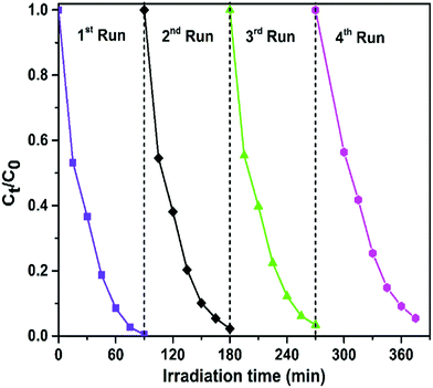
In addition to the photocatalytic activity, the stability of photocatalysts is another important parameter for practical application. To evaluate the stability and reusability of the FeWO4/CNN composites, recycling reactions were performed for the photodegradation of RhB over the optimized catalyst (10-FWO/CNNs) under sunlight irradiation (Fig. 9). As shown in Fig. 9, very interestingly, no significant reduction of photocatalytic efficiency was observed up to the fourth cycle (there was a slight decrease derived from the loss of the photocatalyst during the cycling process), which implies the high stability of the photocatalyst during photodegradation. The XRD and FTIR patterns of the 10-FWO/CNN composite were also investigated after four recycling runs. As shown in Fig. S2a and b,† the XRD and FTIR patterns of the 10-FWO/CNN composite before and after reaction reveal that the phase and structure remained unchanged. Therefore, it is evident that the FeWO4/CNN composite does not undergo any photocorrosion or photobleaching during the degradation experiments.
3.3. Photocatalytic mechanism
To investigate the photocatalytic degradation mechanism of the FeWO4/CNN composites, a series of sacrificial agents were used to quench the relevant active species during the photocatalytic process, and the results are shown in Fig. 10a. As shown in Fig. 10a, when AO was added to the reaction system, the photocatalytic efficiency was not obviously changed. Therefore, it seems that holes are not the reactive species. However, when BQ and IPA were added to the reaction system, the photocatalytic efficiencies were reduced from 99.6% to 14.1 and 19.3% for RhB, respectively. Based on the results, it is suggested that ˙O2− and ˙OH are the major reactive species in the photocatalytic reaction system. To further confirm the presence of ˙OH in the FeWO4/CNN system during sunlight irradiation, ˙OH trapping PL experiments using terephthalic acid (TA) as a probe molecule were also carried out (Fig. 10b). As shown in Fig. 10b, after 30 min of irradiation, a strong PL signal is observed at 425 nm and the intensity significantly increased with the irradiation time as compared to dark treatment, which indeed indicates the generation of ˙OH radicals.For the sake of theoretical investigation of the mechanism of photodegradation, the valence band (VB) and conduction band (CB) edge potentials of the FeWO4 and g-C3N4 were determined using the following empirical equations:45
| EVB = χ − Ee + 0.5Eg |
| ECB = EVB − Eg |
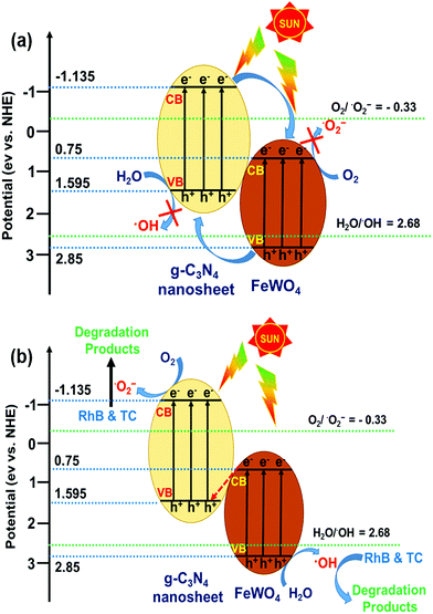
In theory, the photogenerated electrons in the CB of FeWO4 cannot reduce O2 to give ˙O2−, because the CB edge potential of FeWO4 (0.75 eV vs. NHE) is more positive than the standard redox potentials of O2/˙O2− (−0.33 eV vs. NHE).27,45 However, the photogenerated holes in the VB of FeWO4 can oxidize H2O to give ˙OH, because the VB potential of FeWO4 is more positive than the standard redox potentials of H2O/˙OH (2.68 eV vs. NHE).26,58 For the CNNs, because the CB edge potential of CNNs (−1.135 eV vs. NHE) is more negative than the standard redox potentials of O2/˙O2−, the photogenerated electrons can reduce O2 to give ˙O2−. Meanwhile, since the VB potential of CNNs is lower than the standard redox potentials of H2O/˙OH, the photogenerated holes in the VB of CNNs cannot oxidize H2O to give ˙OH.
If the charge carrier transfer in the FeWO4/CNN composites occurs through a type-II heterojunction mechanism (Fig. 11a), the electrons in the CB of CNNs will migrate to the CB of FeWO4, and the holes in the VB of FeWO4 will migrate to the VB of CNNs. As a result, the electrons get accumulated in the CB of FeWO4 and cannot reduce O2 to ˙O2−, and the holes get accumulated in the VB of CNNs and cannot oxidize H2O to ˙OH. Hence, this kind of electron–hole transfer process is not favorable for the formation of active species, and leads to lower photocatalytic activity of the reaction system. Nevertheless, the radical trapping experiment and TAPL analysis implied that ˙O2− and ˙OH are the major reactive species in the FeWO4/CNN photocatalytic system, and the photocatalyst exhibited higher photocatalytic activity. Therefore the separation process of the photogenerated electron–hole pairs in this system did not follow the type-II heterojunction mechanism, but might have occurred through the Z-scheme mechanism.
On the basis of the above experimental results and band structure analysis of FeWO4 and CNNs, a Z-scheme mechanism was proposed to explain the enhanced photocatalytic performance of the FeWO4/CNN composites and is schematically illustrated in Fig. 11b. Under illumination of sunlight, both FeWO4 and CNNs can be excited to generate electron–hole pairs. The photogenerated electrons in the CB of FeWO4 tend to transfer and recombine with the photogenerated holes in the VB of CNNs. In this way, the larger number of photogenerated electrons accumulated in the CB of CNNs can reduce the adsorbed O2 to form more ˙O2−. Meanwhile, the photogenerated holes left behind in the VB of FeWO4 can oxidize the adsorbed H2O to give ˙OH. Therefore, the photocatalytic activity of the FeWO4/CNN system is significantly increased, and RhB or TC is decomposed by ˙O2− and ˙OH reactive species. Therefore, a conclusion can be drawn that the photocatalytic reaction of the as-prepared FeWO4/CNN composites followed a direct Z-scheme mechanism, which could improve the photogenerated electron–hole pair separation and transfer and show a strong oxidation and reduction ability for the effective degradation of organic pollutants.
4. Conclusions
In summary, a series of FeWO4/CNN composites with various contents of FeWO4 have been successfully synthesized through in situ growth of self-assembled FeWO4 nanoparticles on the surface of CNNs via a facile solvothermal method. The as-prepared FeWO4/CNN composites exhibited excellent photocatalytic activity compared to the pure FeWO4, CN, CNNs and mechanically mixed catalyst in the degradation of RhB and TC under sunlight irradiation. This enhancement could be attributed to the high separation and easy transfer of photogenerated electron–hole pairs in the hybrid system, which can be reasonably attributed to the suitable matching of conduction and valence band levels between FeWO4 and CNNs. Besides, a novel Z-scheme photocatalytic mechanism in the FeWO4/CNN system was confirmed by active species trapping experiments and band energy potentials. Moreover, the FeWO4/CNN composites are very stable and reusable during the photocatalytic reactions. Therefore, the novel FeWO4/CNN photocatalysts may have potential for application in pollutant removal as well as water splitting in the future. This work opens up a new feasible avenue to synthesize visible light active Z-scheme photocatalysts for application in energy production and environmental remediation.Conflicts of interest
There are no conflicts of interest to declare.Acknowledgements
One of the authors (Ramakrishna Dadigala) gratefully acknowledges UGC-INDIA for a Senior Research Fellowship. The authors would like to thank the Materials Research Centre, MNIT, Jaipur, India for providing analytical facilities. The authors are also thankful to DST-FIST, New Delhi, India and the Department of Chemistry, Osmania University (OU) and CFRD-OU for providing infrastructure and other necessary facilities.References
- L. Yosefi and M. Haghighi, Appl. Catal., B, 2018, 220, 367–378 CrossRef CAS
.
- S. Bagheri, A. TermehYousefi and T.-O. Do, Catal. Sci. Technol., 2017, 7, 4548–4569 RSC
.
- A. Helal, F. A. Harraz, A. A. Ismail, T. M. Sami and I. A. Ibrahim, Appl. Catal., B, 2017, 213, 18–27 CrossRef CAS
.
- Q. Zheng, D. P. Durkin, J. E. Elenewski, Y. Sun, N. A. Banek, L. Hua, H. Chen, M. J. Wagner, W. Zhang and D. Shuai, Environ. Sci. Technol., 2016, 50, 12938–12948 CrossRef CAS PubMed
.
- X. Qu, P. J. J. Alvarez and Q. Li, Water Res., 2013, 47, 3931–3946 CrossRef CAS PubMed
.
- M. Yan, Y. Wu, Y. Yan, X. Yan, F. Zhu, Y. Hua and W. Shi, ACS Sustainable Chem. Eng., 2016, 4, 757–766 CrossRef CAS
.
- M. N. Chong, B. Jin, C. W. K. Chow and C. Saint, Water Res., 2010, 44, 2997–3027 CrossRef CAS PubMed
.
- F. Opoku, K. K. Govender, C. G. C. E. van Sittert and P. P. Govender, Adv. Sustainable Syst., 2017, 1, 1700006 CrossRef
.
- A. Kubacka, M. Fernández-García and G. Colón, Chem. Rev., 2012, 112, 1555–1614 CrossRef CAS PubMed
.
- H. Kisch, Angew. Chem., Int. Ed., 2012, 51, 2–38 CrossRef
.
- N. Serpone and A. V. Emeline, J. Phys. Chem. Lett., 2012, 3, 673–677 CrossRef CAS PubMed
.
- C. Chen, W. Ma and J. Zhao, Chem. Soc. Rev., 2010, 39, 4206–4219 RSC
.
- F. Le Formal, S. R. Pendlebury, M. Cornuz, S. D. Tilley, M. Grätzel and J. R. Durrant, J. Am. Chem. Soc., 2014, 136, 2564–2574 CrossRef CAS PubMed
.
- R. Li, F. Zhang, D. Wang, J. Yang, M. Li, J. Zhu, X. Zhou, H. Han and C. Li, Nat. Commun., 2013, 4, 1432 CrossRef PubMed
.
- F. Huang, D. Chen, X. L. Zhang, R. A. Caruso and Y. Cheng, Adv. Funct. Mater., 2010, 20, 1301–1305 CrossRef CAS
.
- J. Low, J. Yu, M. Jaroniec, S. Wageh and A. A. Al-Ghamdi, Adv. Mater., 2017, 29, 1601694 CrossRef PubMed
.
- H. Wang, L. Zhang, Z. Chen, J. Hu, S. Li, Z. Wang, J. Liu and X. Wang, Chem. Soc. Rev., 2014, 43, 5234–5244 RSC
.
- Y. Wang, Q. Wang, X. Zhan, F. Wang, M. Safdar and J. He, Nanoscale, 2013, 5, 8326–8339 RSC
.
- P. Zhou, J. Yu and M. Jaroniec, Adv. Mater., 2014, 26, 4920–4935 CrossRef CAS PubMed
.
- K. Maeda, ACS Catal., 2013, 3, 1486–1503 CrossRef CAS
.
- L. Jiang, X. Yuan, G. Zeng, J. Liang, Z. Wu and H. Wang, Environ. Sci.: Nano, 2018, 5, 599–615 RSC
.
- K. Maeda, D. Lu and K. Domen, ACS Catal., 2013, 3, 1026–1033 CrossRef CAS
.
- Y. Sasaki, A. Iwase, H. Kato and A. Kudo, J. Catal., 2008, 259, 133–137 CrossRef CAS
.
- J. Li, H. Yuan and Z. Zhu, RSC Adv., 2016, 6, 70563–70572 RSC
.
- J.-M. Li, H.-Y. Cheng, Y.-H. Chiu and Y.-J. Hsu, Nanoscale, 2016, 8, 15720–15729 RSC
.
- L. Zou, H. Wang and X. Wang, ACS Sustainable Chem. Eng., 2017, 5, 303–309 CrossRef CAS
.
- H. Xu, L. Liu, X. She, Z. Mo, Y. Xu, L. Huang, Y. Song and H. Li, RSC Adv., 2016, 6, 80193–80200 RSC
.
- P. Xia, B. Zhu, B. Cheng, J. Yu and J. Xu, ACS Sustainable Chem. Eng., 2018, 6, 965–973 CrossRef CAS
.
- R. He, J. Zhou, H. Fu, S. Zhang and C. Jiang, Appl. Surf. Sci., 2018, 430, 273–282 CrossRef CAS
.
- J. Li, M. Zhang, Q. Li and J. Yang, Appl. Surf. Sci., 2017, 391, 184–193 CrossRef CAS
.
- D. Xu, B. Cheng, W. Wang, C. Jiang and J. Yu, Appl. Catal., B, 2018, 231, 368–380 CrossRef CAS
.
- W. J. Ong, L. L. Tan, Y. H. Ng, S. T. Yong and S. P. Chai, Chem. Rev., 2016, 116, 7159–7329 CrossRef CAS PubMed
.
- Y. Zheng, L. Lin, B. Wang and X. Wang, Angew. Chem., Int. Ed., 2015, 54, 12868–12884 CrossRef CAS PubMed
.
- X. Wang, S. Blechert and M. Antonietti, ACS Catal., 2012, 2, 1596–1606 CrossRef CAS
.
- Y. Cui, Z. Ding, X. Fu and X. Wang, Angew. Chem., Int. Ed., 2012, 51, 11814–11818 CrossRef CAS PubMed
.
- J. Zhang, G. Zhang, X. Chen, S. Lin, L. Möhlmann, G. Dołęga, G. Lipner, M. Antonietti, S. Blechert and X. Wang, Angew. Chem., Int. Ed., 2012, 51, 3183–3187 CrossRef CAS PubMed
.
- D. A. Giannakoudakis, Y. Hu, M. Florent and T. J. Bandosz, Nanoscale Horiz., 2017, 2, 356–364 RSC
.
- X. Zhou, C. Shao, S. Yang, X. Li, X. Guo, X. Wang, X. Li and Y. Liu, ACS Sustainable Chem. Eng., 2018, 6, 2316–2323 CrossRef CAS
.
- J. Zhang, M. Zhang, R. Q. Sun and X. Wang, Angew. Chem., Int. Ed., 2012, 51, 10145–10149 CrossRef CAS PubMed
.
- G. Zhang, M. Zhang, X. Ye, X. Qiu, S. Lin and X. Wang, Adv. Mater., 2014, 26, 805–809 CrossRef CAS PubMed
.
- X. Dong and F. Cheng, J. Mater. Chem. A, 2015, 3, 23642–23652 RSC
.
- Y. Li, L. Fang, R. Jin, Y. Yang, X. Fang, Y. Xing and S. Song, Nanoscale, 2015, 7, 758–764 RSC
.
- K. Buvaneswari, R. Karthiga, B. Kavitha, M. Rajarajan and A. Suganthi, Appl. Surf. Sci., 2015, 356, 333–340 CrossRef CAS
.
- L. Sun, X. Zhao, C. Jia, Y. Zhou, X. Cheng, P. Li, L. Liu and W. Fan, J. Mater. Chem., 2012, 22, 23428–23438 RSC
.
- K. Huang, Y. Hong, X. Yan, C. Huang, J. Chen, M. Chen, W. Shi and C. Liu, CrystEngComm, 2016, 18, 6453–6463 RSC
.
- X. Cao, Y. Chen, S. Jiao, Z. Fang, M. Xu, X. Liu, L. Li, G. Pang and S. Feng, Nanoscale, 2014, 6, 12366–12370 RSC
.
- Y. Zhou, H. Yao, Q. Zhang, J. Gong, S. Liu and S. Yu, Inorg. Chem., 2009, 48, 1082–1090 CrossRef CAS PubMed
.
- J. Guo, X. Zhou, Y. Lu, X. Zhang, S. Kuang and W. Hou, J. Solid State Chem., 2012, 196, 550–556 CrossRef CAS
.
- Z. Chen, H. Ma, J. Xia, J. Zeng, J. Di, S. Yin, L. Xu and H. Li, Ceram. Interfaces, 2016, 42, 8997–9003 CrossRef CAS
.
- R. Dadigala, R. Bandi, B. R. Gangapuram and V. Guttena, J. Photochem. Photobiol., A, 2017, 342, 42–52 CrossRef CAS
.
- Y. Ma, Y. Guo, H. Jiang, D. Qu, J. Liu, W. Kang, Y. Yi, W. Zhang, J. Shi and Z. Han, New J. Chem., 2015, 39, 5612–5620 RSC
.
- R. Dadigala, B. R. Gangapuram, R. Bandi, A. Dasari and V. Guttena, Acta Metall. Sin., 2016, 29, 17–27 CrossRef CAS
.
- S. Patnaik, G. Swain and K. M. Parida, Nanoscale, 2018, 10, 5950–5964 RSC
.
- Z. Mao, J. Chen, Y. Yang, D. Wang, L. Bie and B. D. Fahlman, ACS Appl. Mater. Interfaces, 2017, 9, 12427–12435 CrossRef CAS PubMed
.
- Z. Lin and X. Wang, Angew. Chem., Int. Ed., 2013, 52, 1735–1738 CrossRef CAS PubMed
.
- N. Cheng, J. Tian, Q. Liu, C. Ge, A. H. Qusti, A. M. Asiri, A. O. Al-Youbi and X. Sun, ACS Appl. Mater. Interfaces, 2013, 5, 6815–6819 CrossRef CAS PubMed
.
- Y. Li, K. Li, Y. Yang, L. Li, Y. Xing, S. Song, R. Jin and M. Li, Chem.–Eur. J., 2015, 21, 17739–17747 CrossRef CAS PubMed
.
- S. Zhang, H. Gao, X. Liu, Y. Huang, X. Xu, N. S. Alharbi, T. Hayat and J. Li, ACS Appl. Mater. Interfaces, 2016, 8, 35138–35149 CrossRef CAS PubMed
.
- S. Chen, Y. Hu, X. Jiang, S. Meng and X. Fu, Mater. Chem. Phys., 2015, 150, 512–521 CrossRef
.
- F. Wang, W. Li, S. Gu, H. Li, X. Liu and M. Wang, ACS Sustainable Chem. Eng., 2016, 4, 6288–6298 CrossRef CAS
.
- J. Sun, J. Zhang, M. Zhang, M. Antonietti, X. Fu and X. Wang, Nat. Commun., 2012, 3, 1137–1139 CrossRef PubMed
.
- X. Zhang, X. Xie, H. Wang, J. Zhang, B. Pan and Y. Xie, J. Am. Chem. Soc., 2013, 135, 18–21 CrossRef CAS PubMed
.
- J. Zhang, Y. Wang, S. Li, X. Wang, F. Huang, A. Xie and Y. Shen, CrystEngComm, 2011, 13, 5744–5750 RSC
.
- S. Chen, Y. Hu, S. Meng and X. Fu, Appl. Catal., B, 2014, 150–151, 564–573 CrossRef CAS
.
Footnote |
| † Electronic supplementary information (ESI) available: A part of the Experimental section, time-dependent UV-vis absorption spectra of rhodamine B and tetracycline solution, and XRD patterns and FTIR spectra of the 10-FWO/CNN composite before and after photocatalytic reaction. See DOI: 10.1039/c8na00041g |
| This journal is © The Royal Society of Chemistry 2019 |

