 Open Access Article
Creative Commons Attribution 3.0 Unported Licence
Modular bioink for 3D printing of biocompatible hydrogels: sol–gel polymerization of hybrid peptides and polymers†
C. Echalierab,
R. Levatod,
M. A. Mateos-Timonedacd,
O. Castañod,
S. Déjeana,
X. Garrica,
C. Pinesea,
D. Noële,
E. Engeld,
J. Martineza,
A. Mehdi*b and
G. Subra *a
*a
aInstitut des Biomolécules Max Mousseron (IBMM), UMR5247 Université de Montpellier, CNRS, ENSCM, Faculté de Pharmacie, 15 Avenue Charles Flahault, 34093 Montpellier, France. E-mail: gilles.subra@umontpellier.fr; Tel: +33 4 11 75 96 06
bInstitut Charles Gerhardt (ICGM), UMR5253 Université de Montpellier, CNRS, ENSCM, Place Eugène Bataillon, 34095 Montpellier, France. E-mail: Ahmad.mehdi@umontpellier.fr; Tel: +33 4 67 14 38 32
cInstitute for Bioengineering of Catalonia (IBEC), Barcelona, Spain
dCIBER en Bioingeniería, Biomateriales y Nanomedicina (CIBER-BBN), Barcelona, Spain
eInstitute for Regenerative Medicine and Biotherapy (IRMB), Inserm U1183, Montpellier, France
First published on 21st February 2017
Abstract
An unprecedented generic system allowing the 3D printing of peptide-functionalized hydrogels by soft sol–gel inorganic polymerization is presented. Hybrid silylated inorganic/bioorganic blocks are mixed in biological buffer in an appropriate ratio, to yield a multicomponent bioink that can be printed as a hydrogel without using any photochemical or organic reagent. Hydrolysis and condensation of the silylated precursors occur during the printing process and result in a covalent network in which molecules are linked through siloxane bonds. The viscosity of the colloidal solution used as bioink was monitored in order to set up the optimal conditions for extrusion printing. Grid-patterned hydrogel scaffolds containing a hybrid integrin ligand were printed using a pressure-driven rapid prototyping machine. Finally, they were seeded with mesenchymal stem cells, demonstrating their suitability for cell culture. The versatility of the sol–gel process and its biocompatibility makes this approach highly promising for the preparation of tailor-made cell-laden scaffolds.
Introduction
3D printing has raised high hopes in regenerative medicine, enabling the on-demand design of structurally complex scaffolds for tissue regeneration. Due to their high content in water, hydrogels are highly attractive biomaterials for 3D printing as efficient extracellular matrix surrogates.1–3 Extrusion, due to the affordability of commercially available 3D printers, and the compatibility with a large number of polymers, has emerged as a method of choice for rapid fabrication of hydrogel constructs.4 It is one of the most straightforward methods for biofabrication: a continuous filament of hydrogel is extruded while the x/y/z movement of the printhead enables it to craft the desired shape. Blueprints from a CAD file are constructed into 3D architectures in a layer-by-layer fashion. The bioink contains the hydrogel precursors and has to be carefully chosen to avoid premature collapse of the printed structure.Various types of physical and chemical hydrogels have been tailored to address this challenge.3 Among physical hydrogels, self-assembling peptide hydrogels are very promising for in vivo applications.5,6 They can be injected thanks to their shear-thinning behavior and are degraded by proteolytic enzymes, yielding non-toxic amino acids and short peptides as metabolites. However, although widely used as drug delivery systems,7 such hydrogels are less favoured for biofabrication as their network only relies on weak non-covalent interactions which impacts their stability and structural integrity when placed in contact with biological fluids and extracellular matrices. The main class of materials used for biofabrication remains chemical hydrogels based on natural or synthetic polymers.3 The control of gelation is of high importance and constitutes the main limitation in the panel of polymers that are used. To prevent the spreading of hydrogel after printing, the viscosity has to be precisely controlled. This entails the careful handling of a pre-polymer solution, which has to gelate quickly enough upon deposition on the printing platform. Biopolymers have their own gelation methods such as complexation of calcium ions for alginate,8 pH adjustment of an acidic solution for collagen,9 and cooling a hot viscous solution for agarose,10 to name a few. One of the concerns about biopolymer is the batch-to-batch reproducibility impacting the gelation kinetics. Cross-linking of soluble polymer was generally employed to increase the stability of the hydrogel. For example, methacrylate groups introduced on biopolymers are commonly used for that purpose, reacting with sulfhydryl containing cross-linkers11 through a Michael-type addition. They may also be used for photo cross-linking.12 Diels–Alders reaction between furan-modified gelatin and maleimide cross-linkers,13 hydrazone formation between aldehyde-modified alginate and hydrazide cross-linkers14 as well as copper-free azide–alkyne cycloaddition15,16 were also investigated. The range of cross-linking strategies is even wider for hydrogels prepared from synthetic polymers. Photo cross-linking remains the most commonly used method,17–19 the transparency of the material enabling an efficient curing process. The bioink, which contains soluble functionalized polymers or monomers and photoinitiators, is UV-irradiated. This can be done while the bioink is flowing out of the nozzle or after printing. Polyhydroxyethylmethacrylate (PHEMA)20 and polyacrylamide (PA)21 scaffolds have been printed by this way.
Materials and methods
Hybrid PEG and hybrid peptide synthesis
The synthesis of hybrid blocks was achieved using 3-isocyanatopropyltriethoxysilane following a previously described procedure.22Preparation of the bioink
Hybrid PEG 1 (10 wt%, 300 mg) and hybrid GRGDSP peptide 2 (1 wt%, 30 mg) were dissolved in DPBS (3 mL) containing sodium fluoride (0.3 wt%, 9 mg).Viscometry
Viscosity measurements were performed using a SV-10 sine-wave vibro viscometer (A&D). The sample cup was filled with 10 mL of the bioink and the viscosity was recorded as a function of time at 37 °C.3D printing
3D printing was performed on an nScript rapid prototyping machine (3Dn-300-TE) at RT using a 3 mL syringe filled with the bioink and fitted with a 200 μm tip. The hydrogel was dispensed on a glass slide at a constant speed of 3 mm s−1 under a pressure ranging from 0.15 to 0.28 MPa.Biological samples
MSCs were isolated from the bone marrow (BM) of C57BL/6 mice. In brief, BM was flushed out from long bones and the cell suspension was plated in minimum essential medium (MEM)-a supplemented with 10% fetal bovine serum (FBS) (Hyclone, Thermo Fisher Scientific, Brebieres, France), 2 mM glutamine, 100 U mL−1 penicillin, 100 mg mL−1 streptomycin (Lonza, Levallois-Perret, France) and 2 ng mL−1 human basic fibroblast growth factor (bFGF) (R&D Systems, Lille, France). MSCs were characterized by immunophenotyping and differentiation capacity towards 3 lineages (chondrocytes, osteoblasts and adipocytes). They were then cultured till sub-confluence, and used between passages 6 and 10.Results and discussion
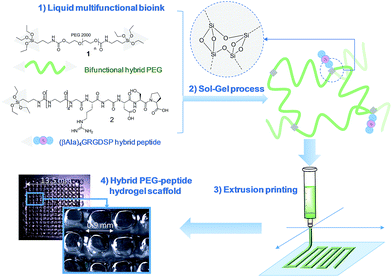
In this study, we propose a novel methodology to 3D print chemically cross-linked hydrogels by using the sol–gel process. To the best of our knowledge, sol–gel was never exploited for biofabrication with hydrogel inks. All examples combining sol–gel and 3D printing deal either with inorganic pattern direct writing23 or with ink-jet printing or extrusion under non-biocompatible conditions.24,25 In Orsi et al.'s work, silane-modified polymers were pre-hydrolysed and used as printable inks. Gel formation was promoted by Si–O–Si formation upon solvent evaporation.23 Chiappone et al. printed 3D structured hybrid materials using both photopolymerization and sol–gel process. The photopolymerization led to the formation of an organic network during the printing step while the inorganic network resulted from the sol–gel process performed after printing, under conditions non-compatible with live cells.24 In contrast, the bioink we have developed enables printing at room temperature, in physiological buffer (pH 7.2), without photoactivation or additional chemical reagents. An alkoxysilane-derivatized synthetic polymer (Fig. 1, bi-functional hybrid PEG 1) solubilized in DPBS undergoes hydrolysis and condensation in the course of the printing process, yielding a covalent hydrogel (Fig. 1).To succeed in an efficient cell colonization of artificial materials and its progressive replacement with natural matrices, cells seeded in the artificial substrate have to differentiate, to migrate and to behave like in their natural environment. This can be induced by diverse biochemical (e.g. growth factors, cell-adhesion peptide ligands) and physical (e.g. pore size, stiffness, rigidity) stimuli distributed within the tissues.26 The sol–gel approach presented in this study is highly attractive since its modularity simplifies the covalent modification of the hydrogel with peptide ligands exhibiting biological activities (i.e. enhancing cell adhesion, stimulating proliferation; etc.). This is a significant breakthrough in this technology, since available 3D printable synthetic polymers such as PEG, PHEMA or PA are not ideal supports as such for cell attachment and have to be further functionalized to improve their cell compatibility.20,27,28 Interestingly, sol–gel could simplify the biofabrication of hydrogel scaffolds of heterogenous composition. Indeed, as a single chemistry system is involved, different bioinks can be prepared to sequentially print layers with different compositions in bioactive components, eliciting specific cell responses in a spatially controlled environment.
We recently demonstrated the feasibility of the sol–gel approach to obtain functional PEG-based hydrogels with either antibacterial or cell-adhesive properties, depending on the hybrid peptide that was used.22 We thus determined a hydrogel composition suitable for cell adhesion which included hybrid RGDSP ligand 2 which displays a trialkoxysilane function at its N-terminus. Once homogeneously mixed in the bioink at the chosen concentration, hybrid blocks (1 and 2) reacted together chemoselectively to form Si–O–Si bonds, guaranteeing both the desired orientation and the correct density of bioactive ligand within the hydrogel matrix.
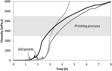
After solubilization of the hybrid silylated precursors 1 and 2 in DPBS, the sol–gel process started with a constant increase of the bioink viscosity. First of all, the progress of sol–gel reaction (i.e. hydrolysis and condensation) was monitored by viscometry. The bioink viscosity was measured as a function of time in order to precisely determine when the bioink could be printed. To do so, a 10 wt% hybrid PEG 1 solution in DPBS containing 0.3 wt% of NaF was prepared and poured into the sample cup of sine-wave vibro viscometer SV-10 (A&D). This apparatus measures the viscosity by detecting the driving electric current necessary to resonate two sensor plates at a constant frequency. Its wide measurement range was well suited to follow the gelation process without damaging the hydrogel. The viscosity of the solution was recorded at 37 °C (Fig. 2) until it reached 10![[thin space (1/6-em)]](https://www.rsc.org/images/entities/char_2009.gif) 000 mPa s, which was the highest value measurable with the apparatus. At the beginning of the experiment, the viscosity of the solution was quite low, around 1.5 mPa s. It increased negligibly for the first two hours when hydrolysis occurred and condensation started. The gel point was observed at 120 min. Afterwards the viscosity increased sharply. We found that printing should be performed when hydrogel viscosity was comprised between 2000 and 5000 mPa s: below 2000 mPa s, the hydrogel tended to spread, whereas above 5000 mPa s, a continuous filament could not be extruded. More precisely, a viscosity between 2500 and 4500 mPa s was ideal for a neat deposition of the hydrogel and was consequently selected for further studies. In order to maintain the hydrogel in the appropriate viscosity range for a prolonged period, we investigated printing at room temperature. After gelation occurred at 37 °C, the temperature was lowered to 25 °C to slow down the sol–gel process. The viscosity was recorded in these conditions (Fig. 2). This change in temperature allowed widening the printing time window from 1 to 2 hours. As already pointed out, one objective of this work was to print RGD-functionalized scaffolds. So the hybrid GRGDSP ligand 2 (20 mol% in regards to 1, 1 wt% in regards to the solvent) was added to the hybrid PEG 1 solution, and the influence on viscosity evolution was studied (Fig. 2). One can notice that gelation was faster with the hybrid GRGDSP 2, gel point was observed at 84 min that is to say 36 min earlier. This phenomenon is due to an overall increase in the concentration of silylated species in the gel precursor solution. Indeed, each monofunctional hybrid peptide may form three siloxane bonds with other silylated building blocks (e.g. bisilylated PEG or silylated peptide). Nonetheless, the presence of the hybrid RGD 2 did not seem to induce any change in the final viscosity and still allowed printing in the same range of viscosity (2500–4500 mPa s) within a 2 hour time frame. This viscosity study has to be conducted for every composition of the bioink as the time window for printing may vary depending on the nature and the concentration of the silylated precursors.
000 mPa s, which was the highest value measurable with the apparatus. At the beginning of the experiment, the viscosity of the solution was quite low, around 1.5 mPa s. It increased negligibly for the first two hours when hydrolysis occurred and condensation started. The gel point was observed at 120 min. Afterwards the viscosity increased sharply. We found that printing should be performed when hydrogel viscosity was comprised between 2000 and 5000 mPa s: below 2000 mPa s, the hydrogel tended to spread, whereas above 5000 mPa s, a continuous filament could not be extruded. More precisely, a viscosity between 2500 and 4500 mPa s was ideal for a neat deposition of the hydrogel and was consequently selected for further studies. In order to maintain the hydrogel in the appropriate viscosity range for a prolonged period, we investigated printing at room temperature. After gelation occurred at 37 °C, the temperature was lowered to 25 °C to slow down the sol–gel process. The viscosity was recorded in these conditions (Fig. 2). This change in temperature allowed widening the printing time window from 1 to 2 hours. As already pointed out, one objective of this work was to print RGD-functionalized scaffolds. So the hybrid GRGDSP ligand 2 (20 mol% in regards to 1, 1 wt% in regards to the solvent) was added to the hybrid PEG 1 solution, and the influence on viscosity evolution was studied (Fig. 2). One can notice that gelation was faster with the hybrid GRGDSP 2, gel point was observed at 84 min that is to say 36 min earlier. This phenomenon is due to an overall increase in the concentration of silylated species in the gel precursor solution. Indeed, each monofunctional hybrid peptide may form three siloxane bonds with other silylated building blocks (e.g. bisilylated PEG or silylated peptide). Nonetheless, the presence of the hybrid RGD 2 did not seem to induce any change in the final viscosity and still allowed printing in the same range of viscosity (2500–4500 mPa s) within a 2 hour time frame. This viscosity study has to be conducted for every composition of the bioink as the time window for printing may vary depending on the nature and the concentration of the silylated precursors.
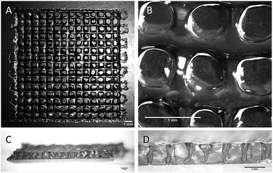
All the printing assays were performed on an nScrypt 3Dn-300-TE rapid prototyping machine (nScrypt, Orlando, FL). This 3D dispensing machine pneumatically deposits a bioink to build up scaffolds layer by layer on a stationary platform. The bioink was prepared by solubilization of the hybrid PEG 1 (10 wt%) and the hybrid GRGDSP peptide 2 (1 wt%) in DPBS containing NaF (0.3 wt%). It was loaded in a 3 mL syringe (fluid dispensing system Nordson EFD) equipped with an air pressure-driven piston. The syringe was incubated at 37 °C until gelation occurred (84 min). Then, it was kept at room temperature (25 °C) for 76 min. The bioink reached the appropriate viscosity for printing (2500 mPa s) 160 min after the beginning of the sol–gel process. At this point, the syringe was fitted with a 27 G conical nozzle (Nordson EFD). A pressure comprised between 0.15 and 0.28 MPa was applied over the piston to dispense the hydrogel. It was tuned to be consistent with the increasing viscosity. A grid pattern was chosen. The scaffold design was a 5 layer stack of porous 13.5 mm squares with 0.9 mm strand spacing (Fig. 3). The deposition of the first layer was crucial for the scaffolding. In order to make the first strands stick and stay in place, glass slides were coated with a thin layer of bioink before printing. Porous 3D scaffolds were successfully printed as the printhead moved at a constant speed of 3 mm s−1 in the xy plane.
 | ||
| Fig. 3 Stereomicroscopy images of the 3D-printed scaffolds. (A and B) Top views; (C and D) side views. All the scale bars represent 1 mm. | ||
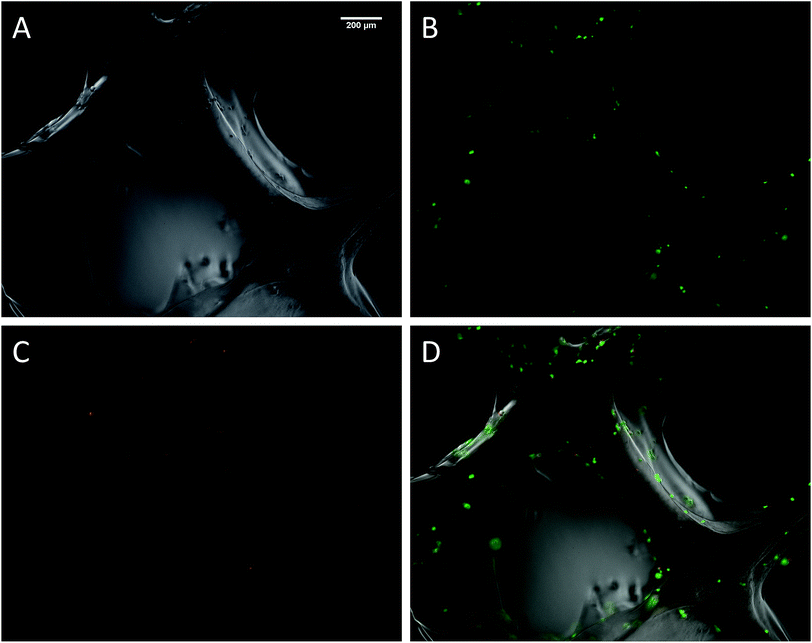
The biocompatibility of the 3D printed scaffolds was assessed on mouse mesenchymal stem cells (mMSC).29 This cell line was chosen in the perspective of tissue engineering applications. As a first step, cells were not added during the printing process but seeded onto the printed scaffolds. Right after printing, the scaffolds were stored in their wet state (in a humidified environment). Since the printing environment was not sterile, the scaffolds were sterilized in an autoclave. The autoclaving step is not compulsory to get stable scaffolds but it is worth noting that this type of treatment has already been used on hybrid materials to drive sol–gel reactions to completeness.30 After this treatment, the scaffolds proved to be stable for at least two weeks in DPBS buffer. Autoclaved scaffolds were allowed to swell in cell culture medium before being cut into discs of 7 mm in diameter. The printed hydrogels were immersed in a cell suspension to undergo a dynamic cell seeding procedure at 37 °C, in a rotating device. Then, the cell-laden constructs were washed with cell culture media and placed in polypropylene tubes filled with media. After 4 days of proliferation, a Live/Dead assay was performed on the scaffolds. Upon observation with a fluorescent microscope, live cells appeared in green whereas dead cells were marked in red (Fig. 4). These results were compared to cells cultured on a PLA scaffold under the same conditions (ESI Fig. S6†). Excellent cell viability was observed in both cases, indicating that the hybrid PEG–peptide 3D scaffolds were suitable for cell culture.
Conclusions
Beyond the printing of hydrogel scaffolds made out of hybrid PEG and hybrid integrin ligand, the combination of sol–gel chemistry and 3D extrusion printing paves the way to unlimited customization of biomimetic matrices. The functionalization of (bio)polymers and small molecules, in particular bioactive peptides, with silyl groups enables formation of the desired network in water, using a single soft chemoselective chemistry. Proceeding at room temperature in biological buffer with mild pressure constraint, this process could be a promising way to prepare cell-laden scaffolds. Encapsulation of cells within the hybrid printable ink is currently under study.Moreover, the combination of several syringes filled with different hybrid bioinks is envisioned to open the way to the biofabrication of multilayer and non-homogeneous biomaterials, mimicking even more closely the complexity of natural tissues in terms of shape and biochemical composition.
Acknowledgements
C. Echalier's PhD was partly founded by the “Région Languedoc Roussillon” through the program “Chercheur d'Avenir”, grant attributed to G. Subra. Peptide synthesis and purification were performed using SynBio3 platform facilities supported by GIS IBISA and ITMO Cancer. The 3D scaffold fabrication was performed using the facilities of the platform of Production of Biomaterials and Biomolecules of the ICTS “NANBIOSIS”, more specifically by the U5 Unit of the CIBER in Bioengineering, Biomaterials & Nanomedicine (CIBER-BBN) at the Institute for Bioenginering of Catalonia (IBEC).Notes and references
- M. Guvendiren, J. Molde, R. M. D. Soares and J. Kohn, ACS Biomater. Sci. Eng., 2016, 2, 1679–1693 CrossRef CAS PubMed.
- P. Bajaj, R. M. Schweller, A. Khademhosseini, J. L. West and R. Bashir, Annu. Rev. Biomed. Eng., 2014, 16, 247–276 CrossRef CAS PubMed.
- J. Malda, J. Visser, F. P. Melchels, T. Jüngst, W. E. Hennink, W. J. A. Dhert, J. Groll and D. W. Hutmacher, Adv. Mater., 2013, 25, 5011–5028 CrossRef CAS PubMed.
- M. E. Hoque, Y. L. Chuan and I. Pashby, Biopolymers, 2012, 97, 83–93 CrossRef CAS PubMed.
- A. Dasgupta, J. H. Mondal and D. Das, RSC Adv., 2013, 3, 9117–9149 RSC.
- A. Altunbas and D. J. Pochan, Top. Curr. Chem., 2012, 310, 135–167 CrossRef CAS PubMed.
- A. Altunbas, S. J. Lee, S. A. Rajasekaran, J. P. Schneider and D. J. Pochan, Biomaterials, 2011, 32, 5906–5914 CrossRef CAS PubMed.
- F. You, X. Wu, N. Zhu, M. Lei, B. F. Eames and X. Chen, ACS Biomater. Sci. Eng., 2016, 2, 1200–1210 CrossRef CAS.
- N. Rajan, J. Habermehl, M.-F. Coté, C. J. Doillon and D. Mantovani, Nat. Protoc., 2006, 1, 2753–2758 CrossRef CAS PubMed.
- M. S. Shoichet, R. H. Li, M. L. White and S. R. Winn, Biotechnol. Bioeng., 1996, 50, 374–381 CrossRef CAS PubMed.
- S. Khetan and J. A. Burdick, Biomaterials, 2010, 31, 8228–8234 CrossRef CAS PubMed.
- H. Aubin, J. W. Nichol, C. B. Hutson, H. Bae, A. L. Sieminski, D. M. Cropek, P. Akhyari and A. Khademhosseini, Biomaterials, 2010, 31, 6941–6951 CrossRef CAS PubMed.
- C. García-Astrain, A. Gandini, C. Peña, I. Algar, A. Eceiza, M. Corcuera and N. Gabilondo, RSC Adv., 2014, 4, 35578 RSC.
- N. Huebsch, P. R. Arany, A. S. Mao, D. Shvartsman, O. A. Ali, S. A. Bencherif, J. Rivera-Feliciano and D. J. Mooney, Nat. Mater., 2010, 9, 518–526 CrossRef CAS PubMed.
- C. A. DeForest and K. S. Anseth, Nat. Chem., 2011, 3, 925–931 CrossRef CAS PubMed.
- H. Jiang, S. Qin, H. Dong, Q. Lei, X. Su, R. Zhuo and Z. Zhong, Soft Matter, 2015, 11, 6029–6036 RSC.
- H. Shih and C.-C. Lin, Biomacromolecules, 2012, 13, 2003–2012 CrossRef CAS PubMed.
- E. A. Phelps, N. O. Enemchukwu, V. F. Fiore, J. C. Sy, N. Murthy, T. A. Sulchek, T. H. Barker and A. J. García, Adv. Mater., 2012, 24, 64–70 CrossRef CAS PubMed.
- J. J. Moon, S.-H. Lee and J. L. West, Biomacromolecules, 2007, 8, 42–49 CrossRef CAS PubMed.
- J. N. Hanson Shepherd, S. T. Parker, R. F. Shepherd, M. U. Gillette, J. A. Lewis and R. G. Nuzzo, Adv. Funct. Mater., 2011, 21, 47–54 CrossRef CAS PubMed.
- R. A. Barry, R. F. Shepherd, J. N. Hanson, R. G. Nuzzo, P. Wiltzius and J. A. Lewis, Adv. Mater., 2009, 21, 2407–2410 CrossRef CAS.
- C. Echalier, C. Pinese, X. Garric, H. Van Den Berghe, E. Jumas Bilak, J. Martinez, A. Mehdi and G. Subra, Chem. Mater., 2016, 28, 1261–1265 CrossRef CAS.
- E. B. Duoss, M. Twardowski and J. A. Lewis, Adv. Mater., 2007, 19, 3485–3489 CrossRef CAS.
- G. Orsi, C. De Maria, F. Montemurro, V. M. Chauhan, J. W. Aylott and G. Vozzi, Curr. Top. Med. Chem., 2015, 15, 271–278 CrossRef CAS PubMed.
- A. Chiappone, E. Fantino, I. Roppolo, M. Lorusso, D. Manfredi, P. Fino, C. F. Pirri and F. Calignano, ACS Appl. Mater. Interfaces, 2016, 8, 5627–5633 CAS.
- B.-S. Kim, I.-K. Park, T. Hoshiba, H.-L. Jiang, Y.-J. Choi, T. Akaike and C.-S. Cho, Prog. Polym. Sci., 2011, 36, 238–268 CrossRef CAS.
- F. Yang, C. G. Williams, D. Wang, H. Lee, P. N. Manson and J. Elisseeff, Biomaterials, 2005, 26, 5991–5998 CrossRef CAS PubMed.
- U. Hersel, C. Dahmen and H. Kessler, Biomaterials, 2003, 24, 4385–4415 CrossRef CAS PubMed.
- C. Bouffi, C. Bony, G. Courties, C. Jorgensen and D. Noël, PLoS One, 2010, 5(12), e14247 Search PubMed.
- M. Fujiwara, K. Kojima, Y. Tanaka and R. Nomura, J. Mater. Chem., 2004, 14, 1195 RSC.
Footnote |
| † Electronic supplementary information (ESI) available: Viscometry data, hydrogel and PLA scaffold printing, cell culture assays, microscopy. See DOI: 10.1039/c6ra28540f |
| This journal is © The Royal Society of Chemistry 2017 |


