 Open Access Article
A novel polymeric precursor for micro/mesoporous nitrogen-doped carbons†
Qiang
Zhao
,
Tim-Patrick
Fellinger
,
Markus
Antonietti
and
Jiayin
Yuan
*
Max-Planck-Institute of Colloids and Interfaces, Department of Colloid Chemistry, Research Campus Golm, Am Muehlenberg 1, D-14476 Golm, Germany. E-mail: jiayin.yuan@mpikg.mpg.de; Fax: +49-(0)331-567-9502; Tel: +49-(0)331-567-9552
First published on 19th February 2013
Abstract
A unique type of homopolymer is introduced in this report as a versatile carbon precursor for the template-free synthesis of porous nitrogen-doped carbons. A poly(ionic liquid) polymer, poly[3-cyanomethyl-1-vinylimidazolium bis(trifluoro methanesulfonyl)imide], when carbonized under nitrogen at intermediate temperatures (500–800 °C) produced readily micro/mesoporous nitrogen-doped carbons without a template or activation agent. Here, the polymer backbone acts as the carbon precursor as well as the nitrogen source, while the bulky counterion plays a role as a molecular template. The carbonization temperature and the heating program were found to play central roles in determining the specific surface area and the nitrogen content in the final materials. Combining this phenomenon with the superior processability of polymers, porous nitrogen-doped carbon nanotubes loaded with Fe2O3 nanoparticles and porous carbon films with tunable thickness were made. The application of Fe2O3 loaded carbon nanotubes in oxygen reduction reaction and the porous carbon film in aqueous dye absorption was demonstrated.
Introduction
Carbon is a fascinating element due to its variety of structural forms with rather different yet unique and tunable physical and chemical properties.1 The application spectrum of carbon and its composites is very broad and covers many aspects of materials science.2–10 Porous carbons are of special interest, because the large surface area facilitates the interfacial mass/energy transport and are thus very important for applications such as adsorbents, catalyst supports, sensors, lithium battery cathodes, supercapacitors, to name just a few.11–25 For a long time polymers have been used as precursors to produce high-value and high-performance carbon materials. The demand for polymeric carbon precursors stems from the convenient preshaping possibility of the carbon precursor. For example, industries have made use of cellulose and polyacrylonitrile fibers for the production of carbon fibers with high flexibility and tensile strength yet low weight and thermal expansion. These polymer processing techniques allow for the shaping of carbon precursors into desirable morphologies and architectures that are kept in the final carbon products.26–28 Other common polymers used as carbon precursors include polyaniline, polyimide, polystyrene, polydivinylbenzene, polyvinylpyridine, polypyrrole, polythiophene, and some more.29Ionic liquids (ILs) are substances consisting of organic cation(s) and anions(s) and melt below 100 °C. They have been studied for nearly one century due to their unique physicochemical properties. Poly(ionic liquid)s, also termed polymerized ionic liquids (PILs), usually synthesized via straightforward chain polymerization of monomeric ILs,30–34 are a subclass of polyelectrolytes bearing a repeating unit being an IL in its nature. Recent interest in PILs expands rapidly in the fields of polymer and materials science.35–42 The incorporation of IL moieties into the polymer chain is motivated to transport some of the unique characters of ILs to the polymeric state, creating new functions and applications.41,43–47 Very recently, PILs have been proven to be capable of acting as a unique class of carbon source.44,45,48–50 Under the same carbonization conditions PIL-based carbons are superior to that from other polymers because of their relatively high structural nitrogen content which can improve the electric and catalytic performance of carbon.51–54
In this contribution, we report on the template-free synthesis of micro/mesoporous nitrogen-doped carbons from a PIL polymer, poly[3-cyanomethyl-1-vinylimidazolium bis(trifluoro methanesulfonyl)imide] (PCMVImTf2N), under nitrogen between 500 and 1000 °C. This was in turn applied to make Fe2O3 loaded porous carbon nanotubes and porous carbon films. Their applications in oxygen reduction reaction and dye sorption were demonstrated. It should be noted that such a self-templating character of homopolymers for porous carbon production has not been reported so far. From a structural point of view, nanostructured bulk block copolymers, one component of which serves as the porogen and the other as a carbon source, might form porous carbon but under very strict conditions. The PIL polymer used here is a structurally simple homopolymer. It was easily prepared via conventional free radical polymerization of an IL monomer 3-cyanomethyl-1-vinylimidazolium bromide (CMVImBr) in DMSO at 90 °C using AIBN as the thermal initiator, followed by an anion exchange step. The synthetic route and the chemical structures of the IL monomer and the PIL polymer are illustrated in Scheme 1.
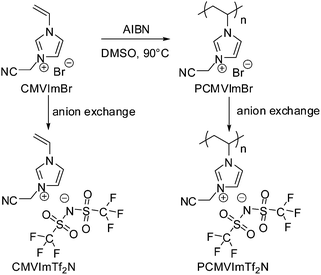 | ||
| Scheme 1 Synthetic route and the chemical structure of ionic liquid monomer CMVImTf2N and PIL polymer PCMVImTf2N studied in this work. | ||
Experimental section and characterization
Materials
1-Vinylimidazole (99%), bromoacetonitrile (97%), potassium bromide (99.0%), lithium bis(trifluoro methanesulfonyl)imide (99.95%), and iron(III) nitrate (99%) were obtained from Sigma-Aldrich and used without further purification. 2,2′-Azobis(2-methylpropionitrile) (98%, Aldrich) was recrystallized from methanol. The ionic liquid monomer, 3-cyanomethyl-1-vinylimidazolium bromide (CMVImBr), was prepared according to our previous paper.45 The solvents and other materials were used as received.Polymerization of CMVImBr monomer
8.4 g of CMVImBr monomer and 160 mg of AIBN were dissolved in 100 ml of DMSO in a 250 ml Schlenk flask. The solution was degassed by high vacuum and backfilled with argon. The polymerization was conducted at 90 °C overnight. After cooling down, the reaction mixture was purified by precipitating twice in acetone. A light yellow solid was obtained and dried at 60 °C under vacuum to a constant weight. Yield: 85%. 1H-NMR (DMSO-d6, δ, ppm): 8.9–9.6 (1H), 7.0–8.4 (2H), 5.2–5.7 (2H), 3.5–4.6 (1H), 1.9–2.7 (2H).Anion exchange of the monomer and PCMVImTf2N polymer
20 g of CMVImBr monomer was dissolved in 200 ml of water. 200 ml of an aqueous solution of 1.05 equivalents of lithium bis(trifluoro methanesulfonyl)imide was added under vigorous stirring. An oil phase formed immediately and the stirring was continued for 1 h. The bottom oil phase was separated from the upper aqueous solution, washed with pure water several times and dried at 40 °C under high vacuum (1 × 10⁻³ mbar) to a constant weight. Yield: 76%. 1H-NMR (DMSO-d6, δ, ppm): 9.5 (1H), 7.9 (1H), 7.5 (1H), 7.2 (1H), 5.9 (1H), 5.6 (2H), 5.5 (1H).20 g of poly(3-cyanomethyl-1-vinyl imidazolium bromide) (PCMVImBr) was dissolved in 800 ml of water under gentle heating. After cooling down, 400 ml of an aqueous solution of 1.05 equivalents of lithium bis(trifluoro methanesulfonyl)imide was added under vigorous stirring. The precipitate was separated by filtration, washed with pure water several times and dried at 60 °C to a constant weight under high vacuum (1 × 10⁻³ mbar). Yield: 92%.
Carbonization process
In a typical experiment, 500 mg of IL monomer or PIL polymer was loaded into an alumina crucible. The sample was heated under nitrogen to a desired temperature (10 °C min−1) and maintained at the final temperature for 1 h. Afterward, the oven was slowly cooled down to room temperature.Preparation of micro/mesoporous nitrogen doped carbon nanotubes
PCMVImTf2N solution in DMF (10 wt%) was dropped on AAO template membranes (Anodic 25, Whatman) for 15 min to infiltrate the PCMVImTf2N solution onto the wall of AAO channels, and the superfluous PIL solution on the AAO surface was gently wiped out by tissue paper. Subsequently, the PIL infiltrated AAO was heated under nitrogen to 800 °C (10 °C min−1) and kept at 800 °C for 1 h. After cooling down, carbonized PIL/AAO membranes were soaked in 1 M HCl to remove the templates, and thoroughly washed by water to obtain carbon nanotubes.Preparation of Fe2O3 loaded nitrogen doped carbon nanotubes
The carbonized PIL/AAO membranes were soaked in an aqueous solution of iron(III) nitrate (15 wt%) for 3 h, during which degassing was applied to facilitate the infiltration of iron salts into carbon nanotubes inside the AAO membrane. Afterwards, PIL/AAO membranes were washed and dried at 80 °C for 30 min. The sample was then heated from 20 °C to 400 °C at 2 °C min−1 under nitrogen, during which the sample was maintained at 140 °C for 6 h and 400 °C for 3 h. The final products were soaked in NaOH (1 M) to remove the AAO templates, and washed with water several times to obtain Fe2O3 loaded carbon nanotubes.Preparation of a micro/mesoporous nitrogen doped carbon film
PCMVImTf2N solution in acetonitrile (0.5–2 wt%) was spin coated onto potassium bromide (KBr) disks. After drying, the disks were heated under nitrogen to 600 °C (10 °C min−1) and carbonized therein for 1 h. After cooling down, the carbonized KBr disks were placed in a clean Petri dish, into which water was added gently. KBr was dissolved soon after the addition of water, leaving a round shaped carbon film.Characterization methods
1H nuclear magnetic resonance (1H-NMR) measurements were carried out at room temperature using a Bruker DPX-400 spectrometer operating at 400.1 MHz. DMSO-d6 and D2O were used as solvents. Elemental analysis was performed for carbon, hydrogen, sulfur and nitrogen using a Vario EL Elemental analyzer. X-ray diffraction experiments were done with a Bruker D8 diffractometer using Cu Kα radiation (λ = 0.154 nm) and a scintillation counter. Nitrogen sorption measurements were performed with a Quantachrome Autosorb-1 at liquid nitrogen temperature. The specific surface area and pore size distribution were calculated using the Brunauer–Emmett–Teller (BET) equation, and the density functional theory (DFT) method, respectively. Samples were degassed at 120 °C for 20 h prior to BET measurements.Transmission electron microscopy (TEM) was performed on a Zeiss EM 912 Omega microscope operating at 120 kV. Scanning electron microscopy (SEM) was performed on a GEMINI LEO 1550 microscope at 3 kV. Field emission scanning electron microscopy (FESEM) was performed on a LEO 1550-Gemini instrument. The samples were loaded on carbon coated stubs and coated by sputtering a Au–Pd alloy prior to imaging.
The electrocatalytic activity towards the oxygen reduction reaction (ORR) was investigated using a Gamry rotating disk electrode setup conducted with a Gamry reference 3000 potentiostat. Cyclic voltammetry (CV) and linear sweep voltammetry (LSV) were carried out in 0.1 M KOH. Prior to measurement the electrolyte was purged for 20 min with inert gas (N2) and reactive gas (O2), respectively. Electrocatalytic reduction kinetics was evaluated applying the Koutecky–Levich equation on the rotational speed dependent currents at a potential of −0.35 V vs. Ag/AgCl.
Results and discussion
In an initial attempt, the carbonization of the ionic liquid monomer CMVImTf2N and the PIL polymer PCMVImTf2N were conducted parallelly under the same conditions to ensure direct comparability. The heating rate was fixed at 10 °C min−1 to approach a desired final temperature (350–1000 °C), and then kept at this temperature for 1 h. The obtained products were characterized by nitrogen sorption and elemental analysis measurements (Table 1 and Fig. 1). As expected, the carbonization yield (weight ratio of the residue to the starting material) drops with increasing temperatures (Fig. 1A). The biggest weight loss step, 22–23 wt%, occurred between 350 and 500 °C, beyond which the mass loss is relatively slow and smooth. At 1000 °C, the highest temperature tested in our experiments, still 20 wt% of the residue was obtained. Such a high yield can be explained by the superior thermal stability of the ionic liquid moieties in PCMVImTf2N.| T/°C | 350 | 500 | 600 | 700 | 800 | 1000 | |
|---|---|---|---|---|---|---|---|
| Carbonization yield (%) | M | 55 | 33 | 31 | 27 | 24 | 20 |
| P | 55 | 32 | 29 | 26 | 24 | 21 | |
| Specific surface area (m2 g−1) | M | <10 | 593 | 752 | 738 | 599 | 219 |
| P | <10 | 593 | 754 | 623 | 561 | 35 | |
| Nitrogen content (%) | M | 12.0 | 24.2 | 24.9 | 23.5 | 21.1 | 10.2 |
| P | 11.6 | 22.5 | 23.9 | 19.7 | 18.4 | 7.4 | |
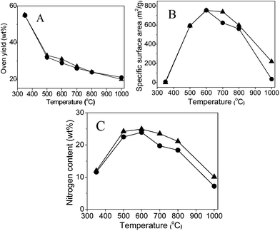 | ||
| Fig. 1 Plots of carbonization yield (A), specific surface area (B) and nitrogen content (C) vs. carbonization temperature of the carbonized products from the IL monomer CMVImTf2N (solid triangles) and the PIL polymer PCMVImTf2N (solid circles). | ||
The specific surface area (SBET) of the carbon products derived at 350 °C from both the IL monomer and PIL polymer is rather low (<10 m2 g−1) (Fig. 1B), i.e. a non-porous material. A larger SBET value close to 600 m2 g−1 was obtained via carbonization of both CMVImTf2N monomer and PCMVImTf2N PIL at 500 °C. An even higher SBET value of 750 m2 g−1 was obtained for both samples at 600 °C, beyond which it decreases again. This indicates that the pores developed at 600 °C collapse partially at higher temperatures. In general, the carbon samples from the IL monomer and the corresponding PIL polymer show very similar nitrogen sorption isotherms between 350° and 800 °C, which indicates that the pore formation feature of PIL at these temperatures essentially stems from its constructing unit, the IL monomer. At 1000 °C, the SBET value of the PIL sample drops to only 35 m2 g−1, while that of the CMVImTf2N monomer is still reasonably as high as 219 m2 g−1. Following the SBET value, the highest nitrogen content (24.9% for the monomer sample and 23.9% for the PIL sample) was found at 600 °C and a decrease of that at other carbonization temperatures. In the nitrogen content vs. carbonization temperature curve (Fig. 1C), the PIL samples show temperature dependence very close to the monomer samples. From this point of view, it is proven again that the carbon forming process of the PIL polymer is determined by its IL monomer.
The origin of the unusual high SBET values of the carbon materials from the IL monomer and the PIL polymer at intermediate temperatures is believed to stem from the generation of certain porous network structures. The nitrogen sorption isotherms of the PIL-based carbon products prepared at temperatures from 350 to 1000 °C are shown in Fig. 2. It is clearly seen that at 350 °C and 1000 °C the materials are nonporous or poorly porous. Between both, microporous carbons with a slight fraction of mesopores were observed. These isotherms are similar to those obtained from the monomer (ESI, Fig. S1†), supporting that the pore formation mechanism is very much the same. The pore size distribution curves of the carbon products prepared from the monomer CMVImTf2N and PIL PCMVImTf2N at 600 °C with the highest SBET values are shown in Fig. 3. Indeed micropores below 2 nm are the dominant pore species and very small mesopores in the range of 2–5 nm coexist. Mesopores larger than 5 nm and macropores are essentially absent. We suppose that the formation mechanism of the micro/mesopores is similar to that reported by Dai et al.55 It was suggested that the cyano group in the chemical structure of the monomer and polymer underwent trimerization reaction at medium temperatures (>350 °C), first producing a solid triazine-based polymeric network. The large-sized [Tf2N]− anions are trapped in the matrix, and leave the pore structures in the subsequent volatilization of this entity. Products after this point are poor in CF3 and sulfur, thus proving the role of the counterion as a molecular template. In addition, the carbonization of PIL with Br− anion (PCMVImBr) failed to produce any porous structure in this approach, providing an indirect proof that the [Tf2N]− anion indeed acts as the template. The small fraction of mesopores, the size of which is beyond the [Tf2N]− template, is believed to come from the distorted carbonaceous framework. This is caused by the geometric restriction exerted by the polymer backbone, i.e. not all cyano groups can freely adopt the necessary spatial arrangement for the trimerization reaction.
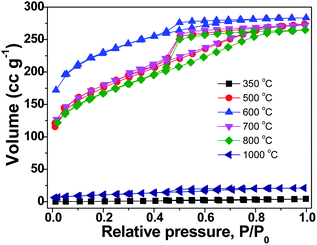 | ||
| Fig. 2 Nitrogen sorption isotherms of the carbon products prepared from PIL PCMVImTf2N at temperatures of 350 to 1000 °C (heating rate: 10 °C min−1, kept for 1 h at the final temperature). | ||
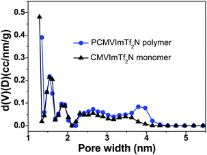 | ||
| Fig. 3 Pore size distribution curves of nitrogen-doped micro/mesoporous carbons prepared from the IL monomer CMVImTf2N and the PIL polymer PCMVImTf2N at 600 °C under nitrogen (heating rate: 10 °C min−1, kept at 600 °C for 1 h). | ||
In the next step, we focused on the improvement of the porous structure of the nitrogen doped carbons prepared from PCMVImTf2N at elevated temperatures, such as 1000 °C. At this temperature, the carbon structure rearrangement is promoted and the graphitic phase is much better developed, which might improve their physical properties (conductivity, chemical stability, etc.) accordingly. For example, the electric conductivity of carbon products from an IL compound 3-ethyl-1-methylimidazolium dicyanamide at 1000 °C was nearly two orders of magnitude higher than that at 800 °C.56 In our system, we monitored the evolution of the crystalline carbon structure via X-ray diffraction (XRD) measurements. As shown in Fig. 4A, the diffraction peaks at 25, 44, and 80° corresponding to the (002), (100) and (110) reflection planes are clearly visible in the carbon sample prepared at 1000 °C. The appearance of the (110) band is usually considered as a proof of triperiodic order and consequently of a real graphitic phase. At low temperatures of 800 °C or 500 °C, the diffraction peaks are unfavorably broader and the (110) reflection plane eventually vanished, indicating poor crystallinity and the absence of a long range structural order. A drawback in synthesizing porous carbons at 1000 °C via this template-free PIL route is the rather low SBET value, only 35 m2 g−1.
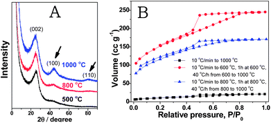 | ||
| Fig. 4 (A) XRD patterns of the carbon products prepared from the PIL polymer PCMVImTf2N at temperatures of 500, 800 and 1000 °C. The curves stack over each other to show the clear evolution of the (100) and (110) bands. The intensity is thus not the absolute intensity. (B) Nitrogen sorption isotherms of carbon products prepared from PCMVImTf2N at 1000 °C with different heating programs. | ||
To overcome this problem, optimization of the carbonization conditions was conducted. We found that by enabling the triazine network fully developed first at intermediate temperatures before the graphitizing temperature can effectively increase the overall specific surface area. For example, when PCMVImTf2N was first heated to 600 °C (10 °C min−1), kept for 1 h at 600 °C and then heated further to 1000 °C (40 °C h−1), the SBET value significantly increased to 520 m2 g−1. In another run, when PCMVImTf2N was dwelled for 1 h at 800 °C before further heating to 1000 °C, a SBET value of 403 m2 g−1 was obtained. In both cases, the SBET increased by more than one order of magnitude without affecting the nitrogen content. From the nitrogen sorption isotherms (Fig. 4B), both micropores and mesopores are present in these two examples. Compared to the nitrogen sorption isotherms in Fig. 2, the mesopores in Fig. 4B are more pronounced. Indeed, by a short dwelling time at intermediate temperatures, this method can deliver micro/mesoporous nitrogen-doped carbons with a large SBET value in a broad temperature range, even at 1000 °C.
Being a polymer in nature, PILs are mechanically more stable than the ILs and can be easily processed into designable shapes and forms.48 Combining this character with the pore forming property of PCMVImTf2N, one can generate shaped micro/mesoporous nitrogen-doped carbon materials in one step. Here we demonstrate this potential with two examples, carbon tubes and films. The preparation of porous carbon nanotubes was conducted using AAO membranes (200 nm in channel size) as templates. The inner channel of AAO was filled with a PCMVImTf2N solution in DMF. As PILs are surface active materials, as demonstrated recently by Texter et al.,36,57 they formed a thin coating on the inner wall surface. The thickness is in fact tunable via the polymer concentration. The PIL film was then converted to carbons in situ during the carbonization, and the carbon product after AAO removal was characterized by TEM and SEM. As shown in Fig. 5, micron meter long carbon nanotubes with a diameter of 200 nm and a wall thickness of 5 nm were obtained from a 10 wt% PCMVImTf2N solution. The tubular shape and their sizes therefore indicate a good replication of the AAO template. Interestingly, the tubes self-stabilize themselves by the formation of periodic cross-layers, which of course is not part of the original template. The specific surface area of these tubes was measured to be 400 m2 g−1. The pore size distribution curve derived from the isotherms proves the existence of micropores coexisting with small mesopores, similar to that of the bulk PIL sample in Fig. 3. It should be mentioned that the IL monomer CMVImTf2N when processed in the same manner also gave a tubular structure, but with a rather lower yield and more irregular structures compared to the PIL approach. These tubes can be used as carrier systems for metal oxide nanoparticles, here exemplified with Fe2O3 nanoparticles. Firstly, the composite of carbon nanotube/AAO membrane was immersed in an aqueous solution of Fe(NO3)3 to allow for the infiltration of iron(III) nitrate into the carbon nanotube interiors under vacuum. After removal of the remainder solution on the outer surface, Fe2O3 nanoparticles were synthesized in situ by thermal decomposition at 400 °C under nitrogen. The AAO template membrane was removed via chemical etching, producing a carbon composite material (CNT@Fe2O3). As shown in the TEM micrographs in Fig. 5E and F, particles with diameters of ca. 5 nm were indeed formed and distributed densely inside the porous carbon nanotubes only (ESI, Fig. S2†). These nanoparticles, which account for a weight content of ca. 70 wt% in the composites, are composed of both maghemite and hematite (ESI, Fig. S3†). The SBET of the CNT@Fe2O3 composites is ca. 250 m2 g−1, which is consistently lower due to the incorporation of nonporous Fe2O3 nanoparticles.
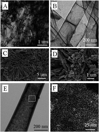 | ||
| Fig. 5 TEM (A and B) and SEM (C and D) images of micro/mesoporous nitrogen doped carbon nanotubes prepared by carbonization of PCMVImTf2N at 800 °C by using AAO as a template. (E and F) TEM images of micro/mesoporous nitrogen doped carbon nanotubes loaded with Fe2O3 nanoparticles. | ||
The morphological structure of micropore containing tubes brings advantageous properties for application in fields such as separation and catalysis, where mass transport plays a crucial role. Interdigitation of the tubes creates macroporous transport “highways” whereas the micropores enhance the active surface area. Carbon nanotubes are commonly used as support materials in electrocatalysis, where they profit also on their high electronic conductivity and thermal stability. In fact nitrogen doped carbons and also Fe2O3 nanostructures were successfully applied as catalysts for the oxygen reduction reaction (ORR), which takes place in the cathode reaction of polymer–electrolyte membrane fuel cells (PEMFCs) and Li–air batteries. For the sake of demonstration, we conducted electrocatalytic ORR tests using a standard rotating disk electrode setup. Herein a thin film of CNT@Fe2O3 composites was prepared on a glassy carbon rotating disk electrode and subjected to electrochemical investigation. Cyclic voltammograms recorded with a scan speed of 100 mV s−1 were measured with and without the presence of oxygen. In the first case the characteristic redox currents of Fe2O3 can be observed, whereas in the presence of oxygen an additional cathodic peak at ∼−0.4 V vs. Ag/AgCl can be observed. The peak can be assigned to the reduction of oxygen clearly demonstrating the electrocatalytic activity of CNT@Fe2O3 composites towards the ORR (Fig. 6A). The result demonstrates the straightforward synthesis of electrocatalytically active materials in an application adapted design. It has to be underlined that the synthetic route allows for gradual variation of parameters such as conductivity, nitrogen content and nature of the deposited catalyst, retaining the overall morphology. Therefore we created a tool to allow the study of single parameters in a complex material system.
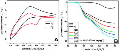 | ||
| Fig. 6 (A) Comparison of cyclic voltammograms of CNT@Fe2O3 composites at 100 mV s−1 after 20 min purge with N2 (black) and O2 (red) in 0.1 M KOH. (B) Linear sweep voltammograms at different rotational speeds recorded at 10 mV s−1 in oxygen saturated 0.1 M KOH. | ||
To further investigate the nature of the reaction, which likewise can be the formation of water in a four electron reaction or the formation of hydrogen peroxide in a two electron reaction, linear sweep voltammograms were recorded in an oxygen-saturated electrolyte at different rotational speeds (Fig. 6B). A characteristic feature of the polarization curves is a missing plateau region at high overpotentials, which we regard as an indication of the good transport of reactants enabled by the materials morphology. Employing the Koutecky–Levich equation for the rotational speed dependent currents at a potential of −0.35 V vs. Ag/AgCl with the result of n = 3.9 reveals a high selectivity towards the here preferred four electron reaction pathway using CNT@Fe2O3 composites as catalysts.
In the case of porous carbon films of various thicknesses, spin-coating of a PCMVImTf2N solution in acetonitrile (0.5–2 wt%) was conducted. KBr disks instead of silicon wafers were utilized, because KBr is insoluble in acetonitrile (≤0.02 wt%), thermally stable in a solid form up to 734 °C and easily removable by washing with water. The spin-coated KBr disks were carbonized at 600 °C, similar to the bulk PIL samples. The film thickness can be effectively controlled by the spin-coating process, e.g. by the polymer concentration and the spin rate. In our experiment, the thinnest carbon film achieved via this method is ca. 50 nm. Fig. 7A shows the carbonized PIL thin film prepared on the KBr substrate prepared from a PIL solution at a low concentration. A freestanding film (Fig. 7B) was obtained when the KBr disk was dissolved in water. SEM characterization in Fig. 7C and D shows that the film is largely homogeneous and planar. Pleats are also observed, which is typical for very thin, flexible films (ESI, Fig. S4†). It must be emphasized that these are special carbon films, where the doping of nitrogen and the micro/mesopore structure introduce extra value. An exemplary application of such films in dye sorption was conducted by using a thicker carbon film (100 μm in thickness) prepared from a concentrated PIL solution. Fig. 7E shows that methyl orange dye molecules were removed effectively by the carbon film, confirming not only the existence of the highly porous structure but also its accessibility to small molecules.
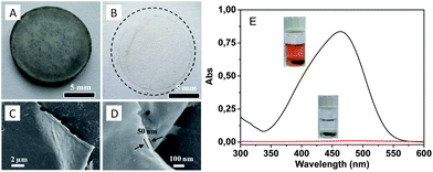 | ||
| Fig. 7 (A and B) Photographs of a carbonized thin film (ca. 50 nm thick) on a KBr disk and floating on water. (C and D) SEM images of the as-synthesized carbon thin films. (E) UV-Vis absorption and optical photographs of methyl orange aqueous solution (0.01 mg ml−1) before (black) and after (red) being treated with a micro/mesoporous nitrogen doped carbon film (100 μm thick). | ||
Conclusions
In conclusion, we demonstrated that a homopolymer PIL, poly[3-cyanomethyl-1-vinylimidazolium bis(trifluoro methanesulfonyl)imide], could be applied as a precursor for micro/mesoporous nitrogen doped carbons. The polymer backbone acted as the material source, while the bulky counter-anion played a role as a molecular template. The effect of the carbonization temperature and the heating program on the formed porous carbon was studied in detail. Under optimized conditions, porous graphitic nitrogen doped carbons were accessible at 1000 °C. Carbons of tubular shape and film morphologies with micro/mesopores were readily obtained via different polymer processing techniques, essentially all in a one-step procedure. The porous carbon nanotubes loaded with Fe2O3 nanoparticles and the porous carbon film were applied as catalysts for oxygen reduction reactions and as sorbents for organic dyes in aqueous solution, respectively. Taking into account the versatility of polymer chemistry, the present data can be extended to a variety of carbon nanomaterials with hierarchical pore structures and expanded functions.Acknowledgements
The authors would like to thank Mr Michael Koebe for the synthesis of the IL monomer and the PIL polymers and the Max Planck Society for financial support. Dr Qiang Zhao acknowledges a Lindau Fellowship (GZ 725) provided by the Sino-German center.Notes and references
- M. Antonietti and K. Müllen, Adv. Mater., 2010, 22, 787 Search PubMed.
- H. Li, S. Pang, S. Wu, X. Feng, K. Mullen and C. Bubeck, J. Am. Chem. Soc., 2011, 133, 9423–9429 CrossRef CAS.
- S. Pang, Y. Hernandez, X. Feng and K. Müllen, Adv. Mater., 2011, 23, 2779–2795 CrossRef CAS.
- S. Yang, X. Feng and K. Müllen, Adv. Mater., 2010, 23, 3575–3579 Search PubMed.
- K. Ariga, A. Vinu, Q. Ji, O. Ohmori, J. P. Hill, S. Acharya, J. Koike and S. Shiratori, Angew. Chem., Int. Ed., 2008, 47, 7254–7257 CrossRef CAS.
- Q. Ji, I. Honma, S.-M. Paek, M. Akada, J. P. Hill, A. Vinu and K. Ariga, Angew. Chem., Int. Ed., 2009, 49, 9737–9739 Search PubMed.
- Q. Ji, S. B. Yoon, J. P. Hill, A. Vinu, J.-S. Yu and K. Ariga, J. Am. Chem. Soc., 2009, 131, 4220–4221 CrossRef CAS.
- P.-X. Hou, W.-J. Yu, C. Shi, L.-L. Zhang, C. Liu, X.-J. Tian, Z.-L. Dong and H.-M. Cheng, J. Mater. Chem., 2012, 22, 15221–15226 RSC.
- L.-F. Chen, X.-D. Zhang, H.-W. Liang, M. Kong, Q.-F. Guan, P. Chen, Z.-Y. Wu and S.-H. Yu, ACS Nano, 2012, 6, 7092–7102 Search PubMed.
- B. Hu, K. Wang, L. Wu, S.-H. Yu, M. Antonietti and M.-M. Titirici, Adv. Mater., 2010, 22, 813–828 CrossRef CAS.
- D. Feng, Y. Lv, Z. Wu, Y. Dou, L. Han, Z. Sun, Y. Xia, G. Zheng and D. Zhao, J. Am. Chem. Soc., 2011, 133, 15148–15156 CAS.
- M. A. Fierke, C.-Z. Lai, P. Bühlmann and A. Stein, Anal. Chem., 2009, 82, 680–688 Search PubMed.
- Z. Wang, F. Li, N. S. Ergang and A. Stein, Chem. Mater., 2006, 18, 5543–5553 CrossRef CAS.
- Z. Wu, Y. Lv, Y. Xia, P. A. Webley and D. Zhao, J. Am. Chem. Soc., 2012, 134, 2236–2245 CrossRef CAS.
- Y. Lv, F. Zhang, Y. Dou, Y. Zhai, J. Wang, H. Liu, Y. Xia, B. Tu and D. Zhao, J. Mater. Chem., 2012, 22, 93–99 RSC.
- J. S. Lee, H. M. Luo, G. A. Baker and S. Dai, Chem. Mater., 2009, 21, 4756–4758 CrossRef CAS.
- X. Wang and S. Dai, Angew. Chem., Int. Ed., 2010, 122, 6814–6818 Search PubMed.
- J. S. Lee, X. Wang, H. Luo and S. Dai, Adv. Mater., 2010, 22, 1004–1007 CAS.
- P. Branton, A.-H. Lu and F. Schüth, Carbon, 2009, 47, 1005–1011 CrossRef CAS.
- A.-H. Lu, W.-C. Li, G.-P. Hao, B. Spliethoff, H.-J. Bongard, B. B. Schaack and F. Schüth, Angew. Chem., Int. Ed., 2010, 49, 1615–1618 CAS.
- A.-H. Lu, W.-C. Li, E.-L. Salabas, B. Spliethoff and F. Schüth, Chem. Mater., 2006, 18, 2086–2094 CrossRef CAS.
- A.-H. Lu, B. Spliethoff and F. Schüth, Chem. Mater., 2008, 20, 5314–5319 CrossRef CAS.
- W.-J. Yu, P.-X. Hou, L.-L. Zhang, F. Li, C. Liu and H.-M. Cheng, Chem. Commun., 2010, 46, 8576–8578 RSC.
- L. Chuenchom, R. Kraehnert and B. M. Smarsly, Soft Matter, 2012, 8, 10801–10812 RSC.
- B. Jache, C. Neumann, J. Becker, B. M. Smarsly and P. Adelhelm, J. Mater. Chem., 2012, 22, 10787–10794 RSC.
- T. Kowalewski, N. V. Tsarevsky and K. Matyjaszewski, J. Am. Chem. Soc., 2002, 124, 10632–10633 CrossRef CAS.
- C. Tang, A. Tracz, M. Kruk, R. Zhang, D.-M. Smilgies, K. Matyjaszewski and T. Kowalewski, J. Am. Chem. Soc., 2005, 127, 6918–6919 CrossRef CAS.
- C. Tang, B. Dufour, T. Kowalewski and K. Matyjaszewski, Macromolecules, 2007, 40, 6199–6205 CrossRef CAS.
- D. Wu, C. M. Hui, H. Dong, J. Pietrasik, H. J. Ryu, Z. Li, M. Zhong, H. He, E. K. Kim, M. Jaroniec, T. Kowalewski and K. Matyjaszewski, Macromolecules, 2011, 44, 5846–5849 Search PubMed.
- K. Vijayakrishna, S. K. Jewrajka, A. Ruiz, R. Marcilla, J. A. Pomposo, D. Mecerreyes, D. Taton and Y. Gnanou, Macromolecules, 2008, 41, 6299–6308 CrossRef CAS.
- S. Amajjahe and H. Ritter, Macromolecules, 2008, 41, 716–718 CrossRef CAS.
- S. Amajjahe and H. Ritter, Macromolecules, 2008, 41, 3250–3253 CrossRef CAS.
- S. Pang, Y. Hernandez, X. Feng and K. Müllen, Adv. Mater., 2011, 23, 2779–2795 CrossRef CAS.
- K. Vijayakrishna, D. Mecerreyes, Y. Gnanou and D. Taton, Macromolecules, 2009, 42, 5167–5174 CrossRef.
- E. B. Anderson and T. E. Long, Polymer, 2010, 51, 2447–2454 CrossRef CAS.
- J. Yuan and M. Antonietti, Polymer, 2011, 52, 1469–1482 CrossRef CAS.
- J. Lu, F. Yan and J. Texter, Prog. Polym. Sci., 2009, 34, 431–448 CrossRef CAS.
- O. Green, S. Grubjesic, S. Lee and M. A. Firestone, Polym. Rev., 2009, 49, 339–360 Search PubMed.
- M. D. Green and T. E. Long, Polym. Rev., 2009, 49, 291–314 Search PubMed.
- M. David, Prog. Polym. Sci., 2012, 36, 1629–1648 Search PubMed.
- Q. Zhao, P. Zhang, M. Antonietti and J. Yuan, J. Am. Chem. Soc., 2012, 134, 11852–11855 Search PubMed.
- Y. Ye, J.-H. Choi, K. I. Winey and Y. A. Elabd, Macromolecules, 2012, 45, 7027–7035 Search PubMed.
- J. Yuan, S. Soll, M. Drechsler, A. H. E. Müller and M. Antonietti, J. Am. Chem. Soc., 2011, 133, 17556–17559 CrossRef CAS.
- J. Yuan, A. G. Marquez, J. Reinacher, C. Giordano, J. Janek and M. Antonietti, Polym. Chem., 2011, 2, 1654–1657 RSC.
- J. Yuan, C. Giordano and M. Antonietti, Chem. Mater., 2010, 22, 5003–5012 CrossRef CAS.
- R. Marcilla, M. Curri, P. Cozzoli, M. Martínez, I. Loinaz, H. Grande, J. Pomposo and D. Mecerreyes, Small, 2006, 2, 507–512 CrossRef CAS.
- J. Pinaud, J. Vignolle, Y. Gnanou and D. Taton, Macromolecules, 2011, 44, 1900–1908 Search PubMed.
- Q. Zhao, T.-P. Fellinger, M. Antonietti and J. Yuan, Macromol. Rapid Commun., 2012, 33, 1149–1153 Search PubMed.
- C. Pan, L. Qiu, Y. Peng and F. Yan, J. Mater. Chem., 2012, 22, 13578–13584 RSC.
- J. Yuan, H. Schlaad, C. Giordano and M. Antonietti, Eur. Polym. J., 2011, 47, 772–781 CrossRef CAS.
- J. P. Paraknowitsch, Y. Zhang and A. Thomas, J. Mater. Chem., 2011, 21, 15537–15543 RSC.
- G.-P. Hao, W.-C. Li, D. Qian and A.-H. Lu, Adv. Mater., 2011, 22, 853–857 Search PubMed.
- X. Jin, V. V. Balasubramanian, S. T. Selvan, D. P. Sawant, M. A. Chari, G. Q. Lu and A. Vinu, Angew. Chem., Int. Ed., 2009, 121, 8024–8027 Search PubMed.
- R. Liu, S. M. Mahurin, C. Li, R. R. Unocic, J. C. Idrobo, H. Gao, S. J. Pennycook and S. Dai, Angew. Chem., Int. Ed., 2011, 50, 6799–6802 CrossRef CAS.
- J. S. Lee, X. Wang, H. Luo, G. A. Baker and S. Dai, J. Am. Chem. Soc., 2009, 131, 4596–4597 CrossRef CAS.
- J. P. Paraknowitsch, J. Zhang, D. Su, A. Thomas and M. Antonietti, Adv. Mater., 2010, 22, 87–92 CrossRef CAS.
- X. Ma, R. Crombez, M. Ashaduzzaman, M. Kunitake, L. Slater, T. Mourey and J. Texter, Chem. Commun., 2011, 47, 10356–10358 RSC.
Footnote |
| † Electronic supplementary information (ESI) available: Some characterizations are presented. See DOI: 10.1039/c3ta10291b |
| This journal is © The Royal Society of Chemistry 2013 |
