
Enhanced photocatalytic CO2 conversion over 0D/2D CsPbBr3/BiOCl S-scheme heterojunction via boosting charge separation†
Fangzheng
Qi
a,
Zengsheng
Guo
a,
Yuhan
Zhang
a,
Xue-Na
Tang
a,
Yiqiang
Sun
 a,
Bo
Xu
a,
Guang-Ning
Liu
*a and
Cuncheng
Li
*ab
a,
Bo
Xu
a,
Guang-Ning
Liu
*a and
Cuncheng
Li
*ab
aSchool of Chemistry and Chemical Engineering, University of Jinan, Jinan 250022, P. R. China
bCollaborative Innovation Center of Yellow River Basin Pharmaceutical Green Manufacturing and Engineering Equipment, University of Jinan, Jinan 250022, P. R. China
First published on 3rd September 2024
Abstract
The stable contact of heterogeneous interfaces and the substantial exposure of active sites are crucial for enhancing the photocatalytic performance of semiconductor catalysts. However, most reported two-dimensional (2D)/2D CsPbBr3 and BiOCl heterostructures are fabricated using electrostatic self-assembly methods, which exhibit significant deficiencies in precise interface quality control and effective active site exposure. In this study, we fabricate a zero-dimensional (0D)/2D CsPbBr3/BiOCl heterojunction via a two-step calcination method, achieving an efficient direct S-scheme configuration. Optimizing interfacial contact and band alignment between CsPbBr3 quantum dots and BiOCl nanosheets enhances cross-plane charge transfer, promoting superior charge separation. This 0D/2D CsPbBr3/BiOCl heterojunction exhibits enhanced carrier mobility and high conversion rates without cocatalysts or sacrificial agents. The mechanism underlying the accelerated S-scheme charge transfer is comprehensively elucidated through a combination of analytical techniques and density functional theory (DFT) calculations. This study offers a novel approach for managing charge carrier segregation and mobility in CO2 reduction photocatalysts.
1 Introduction
The surge in CO2 emissions has triggered an energy crisis and exacerbated the global warming phenomenon.1–4 Leveraging abundant solar energy to propel artificial photosynthesis presents a viable solution for reducing elevated CO2 concentrations in the atmosphere while concurrently producing valuable chemical fuels such as CO and CH4.5–7 Substantial progress has been achieved in the development of photocatalysts with improved catalytic performance, driven by innovative strategies such as single-atom design,8 facet control,9,10 defect engineering,11,12 and heterojunction construction.13,14 Currently, Bismuth oxychloride (BiOCl) featuring a two-dimensional (2D) morphology has garnered widespread attention in the field of photocatalysis due to its excellent chemical stability, minimal photodegradation, and promising potential for various applications.15–18 Unfortunately, rapid recombination of photogenerated charge carriers and inadequate utilization of solar energy have restricted further advancements of BiOCl in the field of photocatalysis. A wealth of previous research has demonstrated that constructing a heterojunction with a semiconductor whose band structure matches that of BiOCl is an effective strategy for improvement. This approach not only enhances the material's efficiency but also effectively suppresses the recombination of photogenerated carriers in BiOCl.19–26 CsPbBr3 perovskite exhibit a band structure that matches with BiOCl, enabling the formation of p–n or S-type heterojunctions.27 This configuration enhances carrier separation efficiency, reduces recombination of photogenerated electrons and holes, prolongs carrier lifetimes, and improves photocatalytic efficiency.28 As of now, reported CsPbBr3/BiOCl heterojunctions have been predominantly prepared using traditional electrostatic self-assembly (ESA) methods. Despite the advantages of simplicity and versatility that ESA offers, significant challenges such as precise control over interface quality, limitations in material compatibility and selectivity, achieving uniform thickness over large areas, and assembly rate pose considerable obstacles, thereby restricting its widespread application.29–32Further, the known CsPbBr3/BiOCl heterojunction materials generally exhibit a 2D/2D layered composite structure.15 By precisely controlling the band structure and interface electronic properties, this face-to-face structure effectively enhances the separation and transport of photogenerated charges, thereby improving the efficiency of catalytic reactions.33,34 On the other hand, due to the high specific surface area and excellent optical properties of 2D materials, 2D/2D heterojunction structures also effectively increase the catalytic active sites and adsorption capacity of catalytic reactions, thus significantly enhancing photocatalytic activity.35,36 However, from the perspective of interface effects, the face-to-face stacking structure increases the interface energy barrier of the heterojunction, while the heterogeneous contact on the cross-section prolongs the transport path of photogenerated carriers, which is detrimental to carrier transport and leads to decreased catalytic efficiency.27 Simultaneously, the lower proportion of exposed BiOCl components on the surface results in a lower specific surface area, significantly reducing active sites during the reaction process. Based on the theory of composite material interface effects, strategies aimed at controlling material component morphology represent effective approaches to address these issues. Compared with the 2D/2D type heterojunctions, reducing the material scale to zero-dimensional (0D) dimension and forming heterojunctions with 2D substrate materials significantly enhances the dynamic characteristics of interface carriers.37–39 Overall, 0D/2D composite materials exhibit a larger specific surface area and more surface atoms, thereby providing increased adsorption and active sites. Furthermore, their size effects not only reduce interface barriers but also enhance carrier transport efficiency, shorten the transport pathways of photogenerated carriers, and consequently improve the overall photocatalytic activity.
In this study, we report a two-step calcination method to synthesize 0D/2D CsPbBr3/BiOCl heterojunction composite material, and first demonstrate its application in CO2 photocatalytic reduction. The BiOCl nanosheets (NSs) followed by the in situ growth of highly dispersed 0D CsPbBr3 quantum dots (QDs) on their surface, which address the issues of crystal quality and structural stability encountered with ESA methods, thereby contributing to the formation of heterojunctions with strong interfacial binding and efficient electronic transport properties. Experimental measurements and theoretical calculation indicate that the 0D/2D CsPbBr3/BiOCl heterostructure exhibits a step-scheme (S-scheme) charge transfer mechanism. This facilitates effective separation of photogenerated electron–hole pairs, enhancing catalytic redox performance and thereby improving photocatalytic activity. The simplified synthesis strategy proposed in this study provides a design pathway to enhance the performance of 0D/2D S-scheme heterojunction photocatalysts.
2 Experimental
2.1 Materials
Ethylene glycol (EG, 99.9%) and Poly (sodium 4-styrenesulfonate) (PSS, 30 wt% in H2O) were purchased from Macklin. Bismuth nitrate pentahydrate (Bi(NO3)3·5H2O, 99%), lead nitrate (Pb(NO3)2, 99.999%), sodium chloride (NaCl, 99.9%), silicon dioxide (SiO2, 99.9%), cesium bromide (CsBr, 99.9%), potassium bromide (KBr, 99.9%) purchased from Aladdin Reagent Co., Ltd.2.2 Synthesis of CsPbBr3 QDs
The synthesis of CsPbBr3 quantum dots was conducted via an improved calcination method. Initially, 0.2 g of SiO2 and 450 μL of a 100 mmol L−1 Pb(NO3)2 solution were thoroughly mixed in a centrifuge tube to form a white paste. After freeze-drying, the resulting powder was transferred to a crucible and calcined at 500 °C for 30 minutes. Subsequently, the calcined powder was transferred back to a centrifuge tube, where 450 μL of a CsBr/KBr mixed solution (with CsBr concentration of 100 mmol L−1 and KBr concentration of 200 mmol L−1) was added before freeze-drying. The final powder was thoroughly ground and then calcined at 500 °C for 60 minutes to obtain CsPbBr3 QDs.2.3 Synthesis of BiOCl NSs
The synthesis of BiOCl NSs commenced with the dissolution of Bi(NO3)3·5H2O (5 mL, 0.25 mol L−1) in a mixed solvent comprising deionized water and EG. Subsequently, a solution of sodium PSS (700 μL) was added dropwise with continuous stirring. Concurrently, an aqueous solution of NaCl (4 mL, 3 mol L−1) was introduced, followed by thorough stirring until the formation of a homogeneous colloidal solution was achieved. The solution was left to stand for several hours to facilitate nucleation and growth. Afterward, the obtained precipitate underwent thorough washing with ethanol and deionized water, followed by overnight drying at 60 °C, yielding the desired BiOCl NSs.2.4 Synthesis of the CsPbBr3/BiOCl Heterojunction
In a standard procedure, 0.2 g of BiOCl was first mixed with 300 μL of a 100 mmol L−1 Pb(NO3)2 solution followed by ultrasonication for 15 minutes and freeze-drying. The resulting powder was ground, transferred to a crucible, and calcined at 500 °C for 30 minutes. Subsequently, 300 μL of a CsBr/KBr mixed solution (with CsBr concentration of 100 mmol L−1 and KBr concentration of 200 mmol L−1) was added to the calcined powder, mixed again, and freeze-dried. The resulting powder was then transferred to a crucible and subjected to calcination at 500 °C for 60 minutes to obtain the CsPbBr3/BiOCl heterojunction material. The mass fractions of CsPbBr3 within the CsPbBr3/BiOCl heterojunction were 10%, 20%, and 30%, designated as 0.1, 0.2 and 0.3 CsPbBr3/BiOCl, correspondingly.2.5 Characterizations
The morphology and structural characteristics of the synthesized samples were meticulously investigated employing various analytical techniques. The morphology and nanostructure were examined using transmission electron microscopy (TEM, JEM-1400) and high-resolution transmission electron microscopy (HRTEM, JEM-2100F). The composition of the product was analyzed by the accompanying energy dispersive spectroscopy (EDS). Concurrently, elemental profiling was conducted using the same instrumentation. The Philips X'pert Pro X-ray diffractometer was employed to obtain X-ray diffraction (XRD) spectra, while an ESCALAB 250 photoelectron spectrometer was utilized for X-ray photoelectron spectroscopy (XPS) analysis. Furthermore, a PE Lambda spectrophotometer was utilized for UV-Vis absorption spectroscopy analysis. In situ diffuse reflection infrared Fourier transform spectroscopy (DRIFTS) analysis was performed in situ using a Nicolet iS50 FTIR spectrometer (Thermo Fisher, USA) to investigate the samples. Electron paramagnetic resonance (EPR) spectroscopy data were acquired using the Bruker A300 spectrometer. Steady-state photoluminescence (PL) was executed employing a Hitachi F-150 spectrophotometer. The photoelectrochemical performance of the specimens was assessed using a CHI 650E potentiostat (Shanghai Chenhua) configured with a three-electrode system. The electrolyte solution comprised tetrabutylammonium hexafluorophosphate (TBAPF6) dissolved in ethyl acetate (EA) at a concentration of 0.1 M, with a 300 W Xenon lamp utilized as the illumination source.2.6 Photocatalytic performance test
The photocatalytic reduction of CO2 was conducted using an automated reaction system (Labsolar-6A, Beijing Perfect Light Technology Co., Ltd, China). As the light source, a 300 W Xe lamp (PLS-SXE300, Perfectlight, China) was employed. The photocatalyst (10 mg) was dispersed in 80 mL of EA and 500 μL of ultrapure water before simulated illumination, subsequently injected into the reactor and vacuumed. The final introduction of CO2 to approximately 80 kPa. The final product was resolved by gas chromatography (GC 2010 PLUS, Shimadzu).3 Results and discussion
The fabrication process of the CsPbBr3/BiOCl heterojunctions involved a two-step calcination method, as illustrated in Fig. 1a. Initially, BiOCl NSs were synthesized successfully at room temperature in a mixture of EG and water using a simple PSS-mediated combinatorial reaction method. Subsequently, CsPbBr3 QDs were integrated onto the BiOCl NSs using a calcination method. The crystal structure of the prepared sample was analyzed using XRD, as depicted in Fig. 1b. It is evident that all the diffraction peaks of BiOCl correspond to the tetragonal BiOCl phase. The XRD patterns of the CsPbBr3/BiOCl heterojunctions exhibited close resemblance to those of pure BiOCl, suggesting that the incorporation of CsPbBr3 QDs did not alter the crystal structure of BiOCl. Due to the low content of CsPbBr3, only its main diffraction peaks can be observed.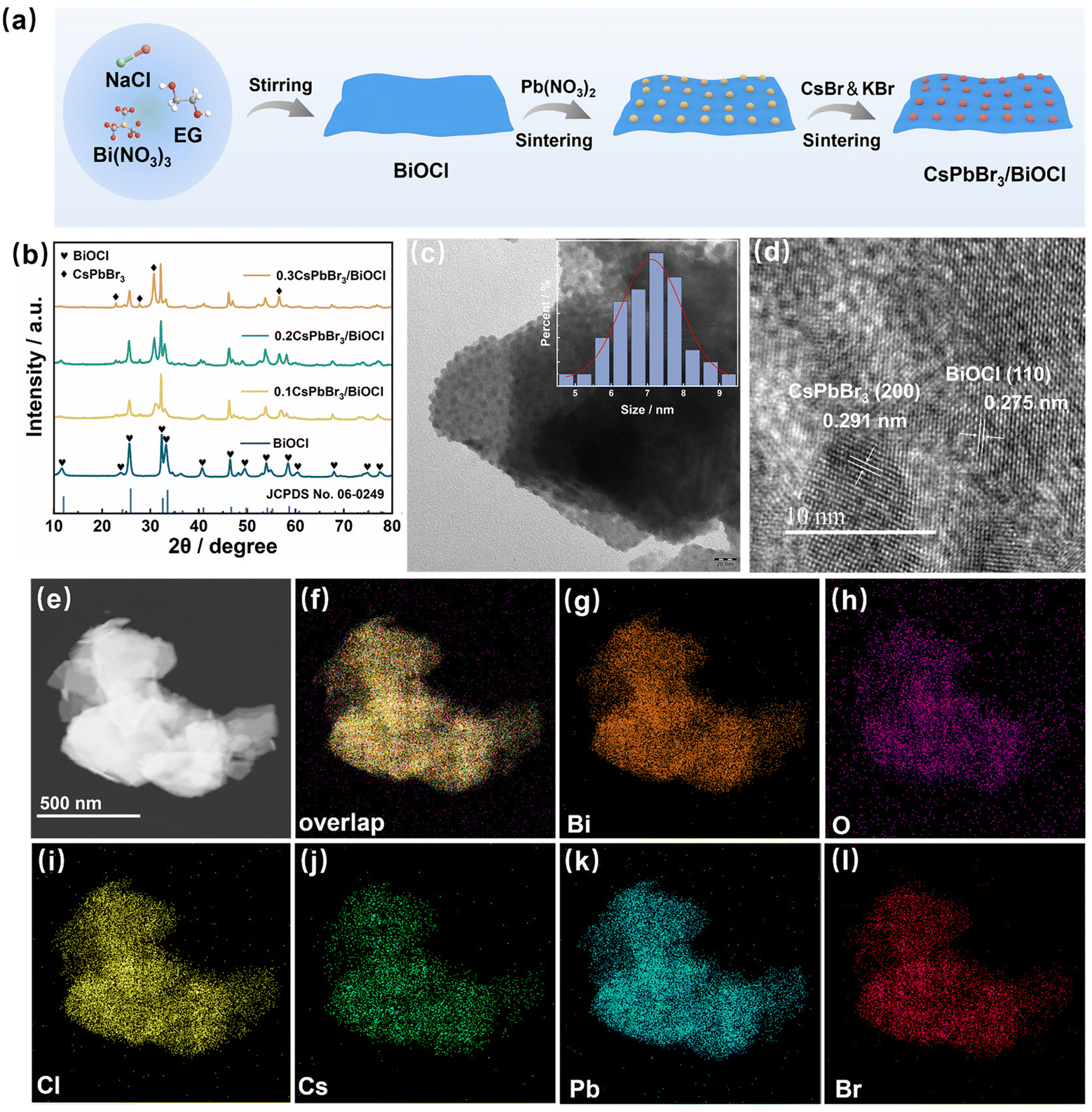 | ||
| Fig. 1 (a) The synthesis path of CsPbBr3/BiOCl photocatalysts. (b) XRD patterns of the samples. TEM (c) and HRTEM image (d) of the heterojunction. (e–l) Elemental mapping of Bi, O, Cl, Cs, Pb and Br elements in the heterojunction. | ||
The topography and microstructure of the samples were examined using TEM and HRTEM. In Fig. S1,† BiOCl appears as a thin slice with dimensions of approximately 70–80 nm. Fig. 1c illustrates the efficient embedding of CsPbBr3 QDs on the surface of the BiOCl NSs. The heterogeneous interface between CsPbBr3 and BiOCl is clearly evident in the HRTEM image of the interface (Fig. 1d), displaying lattice fringes with spacings of 0.291 nm and 0.275 nm, corresponding to the (200) plane of CsPbBr3 and (110) plane of BiOCl, respectively. EDS analysis and Elemental mapping images showed selective concentration of Bi, O, Cl, Cs, Pb and Br elements in the lamellar stacked structure (Fig. S2† and Fig. 1e–l).
The interfacial interaction between CsPbBr3 and BiOCl was thoroughly investigated through XPS characterization. The survey XPS spectrum revealed distinct signals corresponding to Cs, Pb, Cl, Br, Bi, and O elements (Fig. S3†). For CsPbBr3/BiOCl, high-resolution Cs 3d spectra exhibited peaks at 739.02 and 725.04 eV for Cs 3d3/2 and Cs 3d5/2, respectively, indicating a positive shift of 0.67 eV compared to pristine CsPbBr3 (Fig. 2a). Similarly, Pb 4f spectra displayed binding energies of 143.47 and 138.62 eV for Pb 4f5/2 and Pb 4f7/2 respectively, which were higher than those observed in pure CsPbBr3 (Fig. 2b). Conversely, Bi 4f spectra with peaks observed at 164.46 (Bi 4f5/2) and 159.16 eV (Bi 4f7/2) revealed a negative shift of 0.17 eV, compared to BiOCl (Fig. 2c). Additionally, Cl 2p spectra exhibited lower binding energies compared to BiOCl (Fig. 2d). These shifts in binding energies provide compelling evidence for the flow of electrons from CsPbBr3 to BiOCl.
 | ||
| Fig. 2 XPS spectra of (a) Cs 3d, (b) Pb 4f, (c) Bi 4f, and (d) Cl 2p for as-prepared samples. | ||
To further determine the direction of electron migration in heterojunctions, the energy difference between the vacuum energy level (EV) and the Fermi level (Ef) of the semiconductor was calculated by density functional theory (DFT) calculations, and the work functions (Φ) of CsPbBr3 and BiOCl were estimated. As can be seen in Fig. 3, the work functions of CsPbBr3 with (200) surface and BiOCl with (110) surface are 5.17 and 7.65 eV, respectively. The work function values indicate that when the two contacts form a heterojunction interface, the electrons in CsPbBr3 will migrate to BiOCl through the interface until the equilibrium of the two components Ef is reached. This directed migration creates an internal electric field (IEF) at the CsPbBr3/BiOCl interface, where CsPbBr3 is negatively charged while BiOCl is positively charged. This result is consistent with XPS analysis, indicating the formation of CsPbBr3/BiOCl heterojunctions.
 | ||
| Fig. 3 Electrostatic potentials of (a) CsPbBr3 (200) and (b) BiOCl (110) facets. | ||
UV-Vis absorption spectroscopy was employed to assess the light absorption capacity of the sample, as depicted in Fig. 4a. The absorption cut-off edges of CsPbBr3 QDs and BiOCl NSs are approximately at 540 and 360 nm, respectively, indicating their excellent photoresponse characteristics. The corresponding Tauc plots are shown in the inset of Fig. 4a, providing estimated bandgap values of 2.11 and 3.37 eV for CsPbBr3 and BiOCl, respectively. The Mott–Schottky (M–S) curve can determine the conduction type and flat band potential (Efb) of the semiconductor. As illustrated in Fig. 4b, both CsPbBr3 and BiOCl exhibit positive slopes of M–S curves, indicating they are n-type semiconductors with Efb values of −0.82 V and −0.64 V, respectively, corresponding to −0.58 and −0.40 eV after converting to the normal hydrogen electrode (NHE). Generally, the conduction band potential (ECB) of n-type semiconductors is approximately 0.10 eV lower than Efb,40 resulting in ECB values of −0.68 eV and −0.50 eV for NHE for CsPbBr3 and BiOCl, respectively. Additionally, employing the equation Eg = EVB − ECB, the valence band potentials (EVB) of CsPbBr3 and BiOCl were calculated as 1.43 eV and 2.87 eV. The Ef − EVB values for CsPbBr3 and BiOCl were determined as 1.78 eV and 1.98 eV, respectively (Fig. 4c). As depicted in Fig. 4d, this staggered band arrangement will facilitate the establishment of S- scheme heterojunctions between them.
 | ||
| Fig. 4 (a) UV-Vis absorption spectra of the samples. The inset displays the Tauc plots. (b) M–S plots of CsPbBr3 QDs and BiOCl NSs. (c) Valence-band XPS spectra of CsPbBr3 QDs and BiOCl NSs. (d) Band structures of CsPbBr3 and BiOCl. | ||
The ESR spectra plays a pivotal role in probing spin-active ˙O2− and ˙OH species, providing compelling evidence for investigating the directionality of electron transfer. As illustrated in Fig. 5a, the consistently observed characteristic peaks of DMPO-˙O2− across all samples suggest efficient reduction of O2 to generate ˙O2− species by photogenerated electrons. Among the evaluated samples, the CsPbBr3/BiOCl heterojunction exhibits the strongest signals, whereas CsPbBr3 QDs and BiOCl NSs display weaker signals, indicating a higher accumulation of photogenerated electrons in the heterojunction. InFig. 5b, the ESR spectra of DMPO-˙OH signals are presented, showing characteristic signals for CsPbBr3, BiOCl, and CsPbBr3/BiOCl. CsPbBr3 displays a relatively weaker signal due to its low oxidation potential, suggesting that most photoexcited holes remain in the valence band (VB) of BiOCl. Drawing from the aforementioned observations, it can be inferred that the charge-transfer process within the heterojunction follows an S-scheme, as illustrated in Fig. 5c. Due to the lower Fermi energy of BiOCl compared to CsPbBr3, electrons from CsPbBr3 naturally migrate towards BiOCl at the interface. This migration reaches equilibrium when their Fermi energies align. In this process, the band edges of BiOCl and CsPbBr3 are bent downwards and upwards, respectively, to establish IEF at the interface from CsPbBr3 to BiOCl. Under this driving force, the excess electrons in the BiOCl conduction band (CB) and the holes in the CsPbBr3 VB are recombined and eliminated, while the useful electrons in the CB of CsPbBr3 and the holes in the VB of BiOCl are retained. Therefore, this S-scheme charge transfer mechanism facilitates efficient charge separation.
 | ||
| Fig. 5 ESR spectra of (a) DMPO-˙O2−and (b) DMPO-˙OH of the samples. (c) S-scheme charge transfer mechanism in heterojunctions. | ||
To further verify the charge separation properties of the catalyst, the samples were tested with PL spectroscopy and photocurrent response. As illustrated in Fig. S4,† the prominent emission peak at 525 nm in the PL spectrum of CsPbBr3 diminished upon integration with BiOCl. This observation strongly suggests that the recombination of photogenerated electron–hole pairs is significantly suppressed during the formation of heterojunctions.41–43 Fig. S5† presents a comparison of the transient photocurrent response of the samples. The heterojunction samples demonstrated higher photocurrent intensity compared to CsPbBr3 and BiOCl, providing further confirmation of the superior carrier separation efficiency within the heterojunction.
CO2 photoreduction experiments were conducted to evaluate the photocatalytic performance of the obtained samples under simulated sunlight. As depicted in Fig. 6a, across all samples, CO was the predominant product, while the yield of CH4 was relatively low. Both CO and CH4 yields increased almost linearly with reaction time (Fig. S6a and b†). Pristine CsPbBr3 exhibited weak CO2 photoreduction activity, with a generation rate of CO + CH4 below 15 μmol g−1 h−1, attributed to its low charge-transfer efficiency, as indicated by PL spectra and photocurrent responses. Notably, in the optimal sample (0.2 CsPbBr3/BiOCl), which yielded 33.08 μmol g−1 h−1 for CO and 2.77 μmol g−1 h−1 for CH4. To visually compare CO2 photoreduction performance more comprehensively, the average electron consumption of the samples (Relectron = 2R(CO) + 8R(CH4)) was calculated, as shown in Fig. 6b. The Relectron of the 0.2 CsPbBr3/BiOCl sample was 88.32 μmol g−1 h−1, surpassing that of CsPbBr3 QDs and BiOCl NSs.
 | ||
| Fig. 6 (a) Comparison of sample product yields under simulated sunlight for 4 hours. (b) Comparison of Relectron of photocatalysts. (c) Stability testing. (d) Control photocatalytic experiments. | ||
Additionally, in order to evaluate the stability of the sample, it was tested 4 times in a row, and the results showed that its activity was well reproducible (Fig. 6c). In addition, to ensure reproducibility of the results, XRD and TEM analyses were performed on the recovered samples, revealing well-preserved crystalline phases and morphology (Fig. S7 and S8†). A series of verifications were carried out to determine the products of the photocatalytic process. As shown in Fig. 6d, no product was detected under shading conditions, while only trace amounts of CO were observed in the absence of a photocatalyst or in an Ar atmosphere, which was attributed to photooxidation of EA.44 Conversely, when exposed to light in the presence of a photocatalyst and CO2, a large amount of CO is generated.
We employed DRIFTS to analyze the intermediates formed on the surface of the CsPbBr3/BiOCl catalyst during photocatalytic CO2 reduction. Time-dependent infrared spectra were recorded while the catalyst was exposed to a humid CO2 atmosphere in the reaction chamber. Prior to visible light irradiation, no peaks were detected due to background correction. However, upon 20 minutes of illumination, several new peaks emerged in the range of 1000–3580 cm−1. Absorption peaks associated with surface-bound OH− and weakly adsorbed gas-phase CO2 were observed around 3580–3400 cm−1. Furthermore, the absorption peak in the range of 2400–2300 cm−1 indicated the catalyst's adsorption capacity for CO2, confirming the strong adsorption capability of the CsPbBr3/BiOCl composite for CO2 (Fig. 7a and b).
 | ||
| Fig. 7 In situ DRIFTS of CO2 and H2O adsorption under visible light irradiation (a–c) and 2D contour map (d–f). (g) Mechanism of CO2 photoreduction in CsPbBr3/BiOCl heterojunction. | ||
Furthermore, as illustrated in Fig. 7c, various carbonate species were identified, including bicarbonate (HCO3−, observed at 1445, 1396, 1182, 1140, and 1098 cm−1), monodentate carbonate (m-CO32−, observed at 1552 and 1493 cm−1), bidentate carbonate (b-CO32−, observed at 1340 and 1285 cm−1), and chelating-bridged carbonate (c-CO32−, observed at 1810, 1763, 1724, and 1682 cm−1). The signal response for CsPbBr3/BiOCl initially increased and then decreased over 20 minutes, corresponding to successive adsorption, activation, and conversion processes. The absorption peak at 1608 cm−1 was attributed to the COOH* intermediate, while peaks at 2070 cm−1 corresponded to CO*, the final product released as CO. Additionally, the characteristic peak of CH3O* (observed at 1010 cm−1), an intermediate product of CH4 was observed, indicating that the presence of a small amount of CH4 product is also reasonable. The intensity mapping of these peaks is illustrated in Fig. 7d–f. The diagram in Fig. 7g outlines the CO2 photoreduction mechanism on the CsPbBr3/BiOCl photocatalyst, as inferred from the preceding findings and analysis.
4 Conclusions
In this study, we have successfully established a novel direct 0D/2D S-scheme heterojunction between CsPbBr3 and BiOCl, forming a promising architecture for CO2 reduction. Via a two-step calcination process, highly dispersed 0D CsPbBr3 QDs is grown in situ on the surface of 2D BiOCl NSs. This nanoscale effect enables greater exposure of surface atoms, providing more active sites to enhance photocatalytic activity. Compared to individual CsPbBr3 QDs and BiOCl NSs, the heterojunction demonstrated significantly enhanced photocatalytic performance under simulated sunlight. This improvement can be attributed to the efficient spatial separation of charge carriers facilitated by the S-type heterojunction, which effectively prolongs the lifetimes of electrons and holes. Through a comprehensive analysis employing XPS spectroscopy, band structure analysis, ESR spectroscopy and DRIFTS, we systematically investigated the charge transfer mechanism within the S-type heterojunction. We anticipate that this heterostructure will provide valuable insights for advancing the photocatalytic capabilities of lead halide perovskites and will find diverse applications in environmental remediation, pollution control, and renewable energy initiatives.Author contributions
Fangzheng Qi: investigation, methodology, writing – original draft. Zengsheng Guo: investigation. Yuhan Zhang: investigation. Xue-Na Tang: methodology. Yiqiang Sun: validation. Bo Xu: validation. Guang-Ning Liu: validation. Cuncheng Li: conceptualization, supervision, writing – review & editing, funding acquisition.Data availability
The data that support the findings of this study are available on request from the corresponding author upon reasonable request.Conflicts of interest
There are no conflicts to declare.Acknowledgements
This study is provided by National Natural Science Foundation of China (Grant No. 52171179), Collaborative Innovation Center of Yellow River Basin Pharmaceutical Green Manufacturing and Engineering Equipment, University of Jinan, Jinan 250022, P. R. China, Jinan City University Integration Development Strategy Project (JNSX2023021).References
- I. Sullivan, A. Goryachev, I. A. Digdaya, X. Li, H. A. Atwater, D. A. Vermaas and C. Xiang, Nat. Catal., 2021, 4, 952–958 CrossRef CAS.
- X. Zhang, X. Li, D. Zhang, N. Su, W. Yang, H. O. Everitt and J. Liu, Nat. Commun., 2017, 8, 14542 CrossRef CAS.
- J. Zhou, X. Zha, Z. Chen, K. Li, H. Sun, J. Wang, K. Lv, S. Cong and Z. Zhao, Appl. Catal., B, 2024, 350, 123911 CrossRef CAS.
- Z. Li, J. Ao, Z. Wang, Z. Huang, Z. Xu, X. Wu, Z. Cheng and K. Lv, Sep. Purif. Technol., 2024, 338, 126557 Search PubMed.
- J. Ran, M. Jaroniec and Q. S. Zhang, Adv. Mater., 2018, 30, 1704649 CrossRef.
- X. Li, K. Li, D. Ding, J. Yan, C. Wang, A. Sónia, Y. Liu and K. Lv, Sep. Purif. Technol., 2023, 309, 123054 CrossRef CAS.
- Y. Li, Z. Ren, M. Gu, Y. Duan, W. Zhang and K. Lv, Appl. Catal., B, 2022, 317, 121773 CrossRef CAS.
- Y. Li, B. Li, D. Zhang, L. Cheng and Q. Xiang, ACS Nano, 2020, 14, 10552–10561 CrossRef CAS PubMed.
- X. Wu, J. Chen, C. Tan, Y. Zhu, Y. Han and H. Zhan, Nat. Chem., 2016, 8, 470–475 CrossRef CAS.
- F. Chen, H. Huang, L. Ye, T. Zhang, Y. Zhang, X. Han and T. Ma, Adv. Funct. Mater., 2018, 28, 1804284 CrossRef.
- Y. Xiao, C. Feng, J. Fu, F. Wang, C. Li, V. F. Kunzelmann, C. Jiang, M. Nakabayashi, N. Shibata, I. D. Sharp, K. Domen and Y. Li, Nat. Catal., 2020, 3, 932–940 CrossRef CAS.
- S. Bai, N. Zhang, C. Gao and Y. Xiong, Nano Energy, 2018, 53, 296–336 CrossRef CAS.
- R. Ye, J. Zhao and B. B. Wickemeyer, Nat. Catal., 2018, 1, 318–325 CrossRef.
- M. Zhu, Z. Sun, M. Fujitsuka and T. Majima, Angew. Chem., Int. Ed., 2018, 57, 2160–2164 CrossRef CAS PubMed.
- Y. Jiang, Y. Wang, Z. Zhang, Z. Dong and J. Xu, Inorg. Chem., 2022, 61, 10557–10566 CrossRef CAS PubMed.
- F. Deng, Q. Zhang, L. Yang, X. Luo, A. Wang, S. Luo, S. Diony and D. Dionysios, Appl. Catal., B, 2018, 238, 61–69 CrossRef.
- M. Gao, D. Zhang, X. Pu, M. Li, Y. Yu, J. J. Shim, P. Cai, S. I. Kim, H. Seo and D. Johnson, J. Am. Ceram. Soc., 2015, 98, 1515–1519 CrossRef CAS.
- H. Gnayem and Y. Sasson, ACS Catal., 2013, 3, 186–191 CrossRef CAS.
- J. Fu, Q. Xu, J. Low, C. Jiang and J. Yu, Appl. Catal., B, 2019, 243, 556–565 CrossRef CAS.
- F. Xu, K. Meng, B. Cheng, S. Wang and J. Yu, Nat. Commun., 2020, 11, 4613 CrossRef CAS PubMed.
- Z. Dong, Z. Zhang and Y. Jiang, Chem. Eng. J., 2022, 433, 133762 CrossRef CAS.
- Y. Zhang, L. Shi and H. Yuan, Chem. Eng. J., 2022, 430, 132820 CrossRef CAS.
- X. Yue, L. Cheng, J. Fan and Q. Xiang, Appl. Catal., B, 2022, 304, 120979 CrossRef CAS.
- J. Mu, F. Teng, H. Miao, Y. Wang and X. Hu, Appl. Surf. Sci., 2020, 501, 143974 CrossRef CAS.
- X. Li, B. Kang, F. Dong, Z. Zhang, X. Luo, L. Han, J. Huang, Z. Feng, Z. Chen, J. Xu, B. Peng and Z. Wang, Nano Energy, 2021, 81, 105671 CrossRef CAS.
- C. Cheng, B. He, J. Fan, B. Cheng, S. Cao and J. Yu, Adv. Mater., 2021, 33, 2100317 CrossRef CAS PubMed.
- H. Zhang, S. Liu, X. Zhang, Y. Wang, L. Zhang and D. Li, J. Mater. Chem. A, 2020, 22, 11323–11332 Search PubMed.
- L. Ma, H. Wu, B. Chen, G. Wang, X. Bing, D. Zhang and D. Kuang, Adv. Mater., 2022, 16, 2102522 Search PubMed.
- E. B. Lindgren, I. N. Derbenev, A. Khachatourian, H. Chan, A. J. Stace and A. E. BesleySmith, J. Appl. Phys., 2016, 120, 154701 Search PubMed.
- S. K. Smoukov, K. J. Bishop, B. Kowalczyk, A. M. Kalsin and B. A. Grzybowski, J. Am. Chem. Soc., 2007, 129, 15623–15630 CrossRef CAS.
- K. Barros and E. Luijten, Phys. Rev. Lett., 2014, 113, 017801 CrossRef CAS.
- E. Bichoutskaia, A. L. Boatwright, A. Khachatourian and A. J. Stace, J. Chem. Phys., 2010, 133, 024105 CrossRef PubMed.
- C. G. Andres;, X. Duan, Z. Fei, H. R. Gutierrez, Y. Huang, X. Huang, J. Quereda, Q. Qian, E. Sutter and P. Sutter, Nature, 2013, 499, 419–425 CrossRef.
- Y. Gong, J. Lin, X. Wang, G. Shi and P. M. Ajayan, Nat. Mater., 2014, 13, 1135–1142 CrossRef CAS PubMed.
- M. Chhowalla, H. S. Shin, G. Eda, L. Li, K. P. Loh and H. Zhang, Nat. Chem., 2013, 5, 263–275 CrossRef.
- Q. Wang, Z. K. Kalantar, A. Kis, J. N. Coleman and M. S. Strano, Nat. Nanotechnol., 2012, 7, 699–712 CrossRef CAS PubMed.
- Y. Wang, J. Jiang, N. Yao, G. Zuo, E. Zhu, X. Guo and Q. Xian, Sci. China Mater., 2024, 67, 1820–1829 CrossRef CAS.
- X. Li, A. Xu, H. Fan, X. Liu, J. Wang, J. Cao, L. Yang and M. Wei, J. Power Sources, 2022, 545, 1–9 Search PubMed.
- N. M. Gupta, Renewable Sustainable Energy Rev., 2017, 71, 585–601 CrossRef CAS.
- Y. Liu, Y. Lv and Y. Zhu, Appl. Catal., B, 2014, 147, 851–857 CrossRef CAS.
- K. Li, J. Mei, J. Li, Y. Liu, G. Wang, D. Hu, S. Yan and K. Wang, Sci. China Mater., 2024, 67, 484–492 CrossRef CAS.
- Y. Xu, W. Hou, K. Huang, H. Guo, Z. Wang, C. Lian, J. Zhang, D. Wu, Z. Lei, Z. Liu and L. Wang, Adv. Sci., 2024, 11, 2403607 CrossRef CAS.
- H. Guo, L. Zhou, K. Huang, Y. Li, W. Hou, H. Liao, C. Lian, S. Yang, D. Wu, Z. Lei, Z. Liu and L. Wang, Adv. Funct. Mater., 2024, 2402650 CrossRef.
- F. Yang, M. Yang, B. Chen, X. Wang, H. Chen, D. Kuang and Y. Cheng, J. Am. Chem. Soc., 2017, 139, 5660–5663 CrossRef.
Footnote |
| † Electronic supplementary information (ESI) available. See DOI: https://doi.org/10.1039/d4dt02322f |
| This journal is © The Royal Society of Chemistry 2024 |