
A review on solid–solid heterogeneous interfacial interactions in electrocatalytic conversion of inorganic molecules
Wen-Xuan
Liang†
ab,
Huimin
Han†
ac,
Chun-Hua
Zhen
b,
Yingjie
Hua
c,
Jun-Tao
Li
 a and
Yao
Zhou
*a
a and
Yao
Zhou
*a
aCollege of Energy, Xiamen University, Xiamen 361005, Fujian, China. E-mail: zhouy@xmu.edu.cn
bCollege of Chemistry and Chemical Engineering, Xiamen University, Xiamen 361005, Fujian, China
cSchool of Chemistry and Chemical Engineering of Hainan Normal University, Key Laboratory of Electrochemical Energy Storage and Energy Conversion of Hainan Province, Key Laboratory of Electrochemical Energy Storage and Light Energy Conversion Materials of Haikou City, Haikou, 571158, China
First published on 16th November 2024
Abstract
In electro-catalytical conversion of inorganic molecules, solid–solid interfaces universally form during the synthesis of electrocatalysts and the preparation of electrodes; they can also form during the electrochemical process of charging or discharging. In this feature article, the various solid–solid interfaces in porous electrodes are covered. In particular, by referring to studies in our group, a concept of a specific interfacial area is proposed, which provides an index to evaluate solid–solid interfacial interactions at the meso-scale; furthermore, two types of solid–solid interfacial interactions at the micro-scale, namely the van der Waals interface and the covalent interface, are discussed and compared in terms of their efficiency in electrocatalysis; empirical yet general guidelines for construction of solid–solid heterogeneous interfaces which support efficient interfacial electron transfer and electrocatalytic stability are provided accordingly. Last but not least, the role of interfacial electron delocalization behaviors in modulating the local electronic structure of the active sites and catalytic activity is emphasized. With this, this feature article aims to showcase the importance and charm of a solid–solid heterogeneous interface in regulating the efficiency of electrocatalysis.
1. Introduction
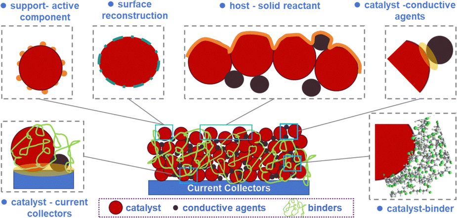
Electrochemical catalysis has emerged as a pivotal field within chemical research, demonstrating significant potential for addressing environmental challenges and advancing energy conversion technologies. Its versatile applications in processes such as hydrogen production via water splitting, fuel cells, carbon dioxide reduction,1,2 electrocatalytic synthesis of ammonia via N2 or NO reduction,3,4 the urea oxidation reaction (UOR),5 metal–oxygen batteries6 and the degradation of organic pollutants underscore its critical role in sustainable development initiatives. For any electrocatalytic process, the reaction kinetics, indexed by the overpotential at a specific current density, are determined by three types of polarizations, namely electrochemical polarization, ohmic polarization and concentration polarization. Historically, in an aqueous electrocatalytic reaction, a solid–liquid interface between an electrocatalyst and an electrolyte has received the most attention most often; in general, the structure of the electrical double layer depends on the solid surface, the applied potential and the composition of the electrolyte.Compared to a solid–liquid interface, a solid–solid heterogeneous interface receives much less attention in electrocatalysis. However, a solid–solid heterogeneous interface exists universally in a porous electrode. As shown in Scheme 1, the interface between a current collector and an electrode active material (which is usually a mixture of active nanoparticles (NPs) and conductive carbon granules being glued on a current collector or a membrane) represents a typical example in this regard. The transfer of electrons across a heterogeneous interface is of paramount importance in redetermining the ohmic polarization, especially under large current density; the solid–solid interface robustness is also critical for the lifespan of an electrode, which sets high requirements on the long-term integrity of this solid–solid interface.7–9
 | ||
| Scheme 1 A schematic depiction of the various solid–solid interfaces existing in a porous electrode. | ||
At the heart of electrocatalytic processes lie catalysts.10,11 Conventional electrocatalysts, such as metal, metal oxides and sulfides, are characterized by their good electrical conductivity, which enables efficient transfer of charge carriers.12–15 However, to achieve a large electrochemically active surface area, active components have to exist as discrete NPs with low dimensions, and the electrical conductivity of the whole electrode can be an issue regardless of their high inherent electrical conductivity. The usage of additional conductive agents is thus necessary.16,17 Meanwhile, for dispersion and stabilizing concerns, e.g., when a noble metal is employed,18 the usage of catalytic supports which are usually conductive carbon or semiconductors is also a necessity.19,20 Within such a porous composite, there exists extensive contacts among the different solid particles, forming another type of solid–solid heterogeneous interface in addition to the one between the electrode active materials and the current collector; to accomplish low ohmic polarization, efficient interfacial transportation of charge carriers among the various discrete particles is also important.
Despite concerns on conductivity and dispersion, the solid–solid heterogeneous interaction provides an approach to modulate the local electronic structure of the catalytically active sites. In this scenario, a synergistic effect between the solid phases with different compositions which are rationally joined in space has often been reported. In this sense, an auxiliary solid (with respect to the catalytically active component) functions more than merely supporting or stabilizing the active component; it is also an electron modulator, which can donate to or withdraw electrons from the active solid depending on the factual work function between the two. One prominent example is the dispersion of metal-based NPs on carbon-based or other semiconductor-based materials.19,21 This configuration not only enhances the spatial distribution of the metal NPs preventing agglomeration but also modulates the electronic structure of the catalytic sites through interfacial effects, leading to improved catalytic efficiency.22
Solid–solid interfaces can not only form during the synthesis of catalysts and the preparation of electrodes, but they can also form in an on-site manner during an electrochemical process (Scheme 1). Typical examples of this category are associated with the charging and discharging processes of batteries using a metal (e.g., Li or zinc) as an anode. The cathode reactions during discharge usually involve electrocatalytic conversion of inorganic reactants (e.g., O2 or CO2 or S8 or I2) to the respective reducing state; during charge, the as-formed discharge products (e.g., Li2O2, Li2CO3, amorphous carbon, Li2S etc.) would be electrocatalytically oxidized or decomposed. In these processes, either the reactants can exist collectively as solid aggregates (e.g., S8 or I2), or the discharge products, which serve as the reactants in the charging process, are solids, taking for example Li2CO3 formed in a Li–CO2 battery and Li2O2 formed in Li–O2 or Li–air batteries.23–26 Hence, the interfacial transfer of electrons between the conductive carbon and the solid reactant is of great importance for minimizing the discharge–charge potential gap or polarization.
On this basis, as can be seen, for electrocatalysis in both aqueous or organic media, solid–solid interactions occur universally due to the integration of two-phase or multiphase catalysts, the combination of catalysts with a conductive collector, or even between the catalyst and the solid reactant. To achieve efficient electronic interactions between two solids, in addition to the inherent work function of each solid, intuitively, the interfacial intimacy, which is determined by the surface roughness, the distance between the two surfaces, as well as the portion of interfacial atoms within the multiphase composite, shall also be carefully tuned; the local electronic structure of the interfacial atoms as well as the chemical affinity shall also be considered.
In this feature article, we present a review of research on electrocatalytic conversion of the various above-mentioned inorganic molecules in our group, with a focus on construction of solid–solid interfaces and exploration of their role in regulating the electrocatalytic activity. The factors affecting the solid–solid interaction strength were summarized. A straightforward but practically useful term, specific interface area (SIA), has been proposed, which depends on the geometry of two solids of concern as well as the way how they are being interfaced or positioned to each other. The SIA can be used to qualitatively evaluate the strength of the interfacial interaction; a larger SIA is associated with larger or more intensive interfacial interactions, which can serve as a guideline for efficient design of a solid–solid interface. The types of a solid–solid interface existing in an electrode and the different mechanisms through which they affect the electrocatalytic conversion of various inorganic molecules in both aqueous electrolytes and organic electrolytes are also covered by referring to typical examples in our research. The challenges and limitations of current research on this topic have also been discussed.
2. Structural features of solid–solid heterogeneous interfaces
2.1 Geometric concern at the meso-scale
A distinct characteristic between a solid and a liquid or a gas is that it has a clear and constant shape and also hardness or mechanical strength regardless of its size. While two solids can interact with each other easily through instantaneous physical contact,27–29 it is often not easy or spontaneous for two solids to form a stable and intimate solid–solid interface. The reasons are obvious. To induce connection or bonds between the surface atoms of two solids, it requires not only the copresence of surface atoms of two phases but also places harsh requirements on how they are sterically positioned with respect to each other, their surface topography, and surface activity. This can be relatively easily satisfied at the atomic or molecular scale for a solid–liquid or solid–gas interface, which however is challenging for a solid–solid interface since surface atoms in a solid suffer from much larger steric hindrance and lack of freedom compared to those in a fluent counterpart.Intuitively, as shown in eqn (1), based on our various research examples, we propose that the intimacy and affluency of a solid–solid interface can be simply indicated by the specific interface area (SIA), which is the ratio of the interface area (S1–2) to the total mass of the two joined solids m1 and m2, as shown in eqn (1).
| SIA = S1–2/(m1 + m2) | (1) |
| SIA = 1/(ρ1r1 + ρ2r2) | (2) |
In an ideal case, for example, when the two adjacent solids assume a core–shell or layered configuration, the two solid surfaces are almost parallel to each other. As shown in Fig. 1a and eqn (2) where ρ is the density of the solid and r is the thickness of the solid in the direction normal to the interface, the so-called SIA in this case is inversely proportional to the thickness r. Straightforwardly, the thinner the active phase and the auxiliary phase are, the larger the SIA would be, and the stronger the interfacial interaction would be.
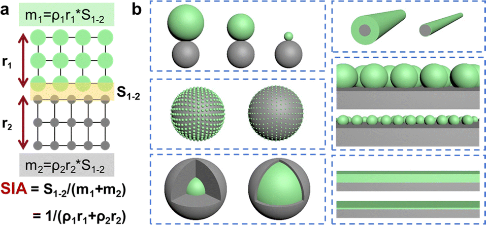 | ||
| Fig. 1 (a) Depiction of the specific interface area (SIA) and (b) schemes showing the various solid–solid contact modes with different specific interface areas. | ||
In reality, the SIA really depends not only on the dimension but also on the geometry and the configuration. Fig. 1b shows the various ways how two solids with different shapes can be interfaced with each other. Obviously, to achieve a large SIA, solids shall have a smaller size and low dimension, and two solids shall be parallel to each other, that is, the composite shall assume a core–shell or layered configuration. To this end, the solidification kinetics which involves nucleation and growth of the solids shall be optimized specifically depending on the individual research case.
2.2 Examples of inducing a large SIA for efficient conversion of inorganic small molecules
As simple as it is, this concept of SIA provides a general guideline to follow for design of electrocatalysts with solid–solid interfaces. As shown in Fig. 2a, for example, in the design of metal hydroxide coated gold NPs (AuNCs@M(OH)2, M = Mn, Co, or Ni), the deposition kinetics of M(OH)2 has been controlled so that their thickness can be controlled to be less than 4.0 nm (Fig. 2b–e). With a core–shell configuration and a thin amorphous layer, a large SIA can be obtained; as such, there exists a strong solid–solid interaction between the semiconductor M(OH)2 and the assembled Au NPs, which have much higher conductivity and electronegativity that were found to enhance the electroactivity of Ni(OH)2 and Co(OH)2 towards the oxygen evolution reaction (Fig. 2f).30 | ||
| Fig. 2 (a) Synthesis of core–shell structured AuNCs@M(OH)2, (b)–(e) TEM images of AuNCs@M(OH)2, (f) current density at an overpotential of 0.42 V for the oxygen evolution reaction (OER) by AuNCs@M(OH)2 and their comparisons;30 (g) synthesis of CuTAB@Cu, (h) and (i) SEM, (j) and (k) HRTEM images of CuTAB@Cu, (l) faradaic efficiency (FE) of CuTAB@Cu, and (m) LSV profiles of CuTAB@Cu, CuTAB, and Cu2O@Cu.31 | ||
Another similar example in this regard is a core–shell structured nanocomposite formed between the highly conductive Cu nanowire and the 1,2,4,5-tetraaaminobenzene (TAB) (Fig. 2g).31Fig. 2h–k show the topography of CuTAB@Cu: bumpy aggregates of small NPs are observed on its surface, and the TEM observation further confirms the core–shell structure. The outside thin nanoshell is a CuN4-based CPP (Cu-TAB) polymer where Cu2+ is tetra-coordinated via four dsp2 hybrid orbitals with four N-containing groups in TAB. Though it possesses numerous Cu–N4 sites which shall be active for electroreduction of CO2, bulky Cu-TAB aggregates showed little electrocatalytic activity. Interestingly, when being interfaced with metallic Cu nanowires, as shown in Fig. 2l and m, by carefully tuning the thickness of the Cu-TAB nanoshell, Cu-TAB becomes highly active and CO2 is mainly converted to liquid products, with a FE of 46% towards ethanol at a potential of −0.55 V vs. RHE. The thickness of the Cu-TAB nanoshell was found to be important to enable high activity.
The above-mentioned SIA also provides the first guideline when designing electrocatalysts for metal batteries which involve conversion or formation of insulating solid reactants or products in the cathode during charge and discharge. A large SIA between the electrocatalyst (which is often a conductive carbon) and the reactant is necessary to ensure fast conversion kinetics and low polarization. In this scenario, the electrocatalyst actually serves as the host. To obtain high SIA, the host first of all shall have high specific surface area and large porosity to accommodate the insulating solid reactant and help dispersion of the insulating solid reactant.
Following such a guideline, carbonaceous hosts with large voids and ECSAs have been developed as cathode electrocatalysts for metal secondary batteries (e.g., Li–S batteries). Meanwhile, to address both the ohmic polarization as well as the electrochemical polarization, a non-polar carbon host can be interfaced with another polar or functional component, which together offer both electroconductivity and catalytic activity to the conversion of the insulating solid reactants during charging and/or discharging. As shown in Fig. 3a–c, by manipulating the anion-exchange process between Ni–Co acetate microcrystals and tannic acid or phytic acid, we have synthesized hollow porous single- or multi-layered hierarchically functionalized carbon nanoshells.24 In particular, the shell-in-shell composite C–NiCoPi@C–Ni2Co has an external Ni2Co-decorated carbon nanoshell and an internal Ni3P-anchored carbon nanoshell encapsulated within a continuous NiCo–phosphate (NiCoPi) layer (Fig. 3f and i). When solid sulfur is loaded into the host, in such a three-layered composite, the carbon nanoshell offers high electronic conductivity; the polar NiCoPi nanoshell offers not only mechanical stability but also catalytic activity in converting the different polysulfide intermediates; hence, both the ohmic polarization and electrochemical polarization can be reduced. Owing to the large void, the polar nature, and high conductivity, it displays collective merits as a sulfur host in Li–S batteries and maintains capacity retention as high as 86% after 500 cycles (Fig. 3j). In addition, we have also designed two-dimensional carbon nanosponge with a rich P-dopant (4.2 at%) and a large specific surface area (1966 m2 g−1) in anchoring I2/Ix− (x = 1, 3 or 5) and catalyzing their mutual conversion in Zn–I2 batteries.23
 | ||
| Fig. 3 Flowchart for design of (a) C–NiCoPi, (b) C–Ni2Co, and (c) C–NiCoPi@C–Ni2Co nanoshells, TEM images with different magnifications of: (d) and (g) C–Ni2Co nanoshell and the inset is the relevant SEM image, (e) and (h) C–NiCoPi nanoshell, (f) and (i) the bilayered C–NiCoPi@C–Ni2Co nanoshell loaded with elemental sulfur, and (j) charge–discharge cycling profiles at a current density of 0.5 C.24 | ||
Notably, in some cases solid reactants such as Li2CO3 and Li2O2 are formed during the discharge of a secondary metal battery, in which the cathode host actually serves as the substrate for nucleation and growth of the as-formed solid discharge products; the lack of intimate atomic interactions at the solid–solid interface of the cathode can lead to excessive overpotential loss during charging.6 In this situation, it is important to induce homogeneous deposition of the discharge products across the electrode to achieve a large SIA. Hence the solid–solid interfacial affinity is also important in addition to the aforementioned porosity and specific surface area, so that the morphology and dimension of the as-formed solid discharge product can be regulated. As the above solid discharge products are mostly polar in nature, in most cases, a metal-relevant moiety or a hybrid dopant is introduced into the carbon host to induce polarity, so as to the enhance the interaction between the host and the solid reactants. Some studies have also shown that the compositions of the electrolyte can also mediate the growth of discharge products in metal–O2 battery systems.6
Examples in this regard are shown in Fig. 4. To guide and accommodate the discharge solid product (Li2O2) for Li–O2 batteries, we have developed a flexible and integrally bilayered CNT-based cathode by in situ growing a layer of numerous microflower-shaped assembly of cobalt nanoparticle-embedded nitrogen-doped carbon nanotubes (CNTs) on a flexible current collector which is also a CNT-interwoven film (FilmCNTs) (Fig. 4a).25 Such an integrally bilayered cathode (FlowerCNTs@FilmCNTs) is not only freestanding and highly porous, but also possesses high electronic conductivity and electrocatalytic activity (Fig. 4b and c); as such, it can support fast oxygen reduction and ensure uniform dispersion of the insulating solid product Li2O2 during the discharge process; during the charge process, as it can support efficient electron transfer across the intimate solid–solid interfaces, including the one between the catalyst layer and current collector and the one between Li2O2 and the catalytic active sites, it enables fast and thorough decomposition of Li2O2 (Fig. 4d). In comparison, in the control sample where carbon nanotubes were being scattered on the CNT-interwoven film, large aggregates of Li2O2 were formed, which resulted in severe polarization during charging (Fig. 4e).25
 | ||
| Fig. 4 (a) Flow chart for preparation of FlowerCNTs@FilmCNTs, (b)–(e) SEM images of fresh/discharged FlowerCNTs@FilmCNTs electrode and discharged CNTs/FilmCNTs electrode;25 (f)–(h) SEM images and schematic drawings of discharged RuO2/CNT, RuO2/Co3O4/CNT, Co3O4/CNT electrode;26 and (i) and (j) Ru/NiO@Ni/CNT and Ru/CNT cathode.32 | ||
Another example is the design of RuO2–Co3O4/CNT as a cathode for Li–CO2/O2 batteries with long-term stability. The strong interfacial interaction between RuO2 and Co3O4 was found to modulate the morphology of Li2CO3 formed during discharging.26 The copresence of RuO2–Co3O4/CNT was found to guide the morphology of the insulating Li2CO3, which existed as a thin layer of membrane-like morphology, coating on the CNTs in a relatively homogeneous way (Fig. 4g). Both the SEM observation and XRD profiles confirm complete decomposition of Li2CO3 after charging when RuO2–Co3O4/CNT was employed as the electrocatalyst, whereas accumulation of Li2CO3 after charging was observed when RuO2/CNT or Co3O4/CNT was used (Fig. 4f and h). The decomposition kinetics of Li2CO3 was also accelerated by the solid–solid interaction between RuO2–Co3O4, according to DFT calculations.26 In another similar study, as shown in Fig. 4i and j, we also noticed that Li2CO3 formed in Li–CO2/O2 on Ru/CNTs tends to exist as a bulky aggregate (Fig. 4j); when a Ni-based moiety is introduced, e.g., for a Ru/NiO@Ni/CNT, Li2CO3 would form in a more uniform way around the CNTs (Fig. 4i), leading to relatively large SIA, which decreases the polarization and is beneficial for the long-term stability.32
In addition to the surface properties of a cathode electrocatalyst, we also found that the reaction kinetics can be modulated by the composition of the gas or the addition of functional additives into the electrolyte, which also provides an opportunity to tune the SIA between the electrocatalyst and the resulting solid discharge product.33,34 For instance, recently, we reported that the presence of trace amounts of ferrocene (an organic transition metal compound with aromatic properties) in an electrolyte can stabilize the discharge intermediates and favor the occurrence of the two-electron reaction path during the CO2RR in the discharge; meanwhile, it has a relatively high adsorption capacity for CO2 and can affect the solvation environment of Li+, which will shorten the path of CO2 binding to Li+ at the reaction interface during the discharge process, promoting the uniform nucleation of discharge products, thereby significantly increasing the discharge capacity.35
2.3 Types of interactions at solid–solid heterogeneous interfaces
While the SIA is an important index to evaluate the strength and extensiveness of the solid–solid interaction at the mesoscale, another important factor at the micro-scale is the surface property, including the saturation level or the coordination number of surface atoms and the chemical affinity. In this regard, depending on the type of forces which join or connect the two solid surfaces, it falls into two types, the van der Waals (VdW) interface and the covalent bonding interface.VdW interfaces, as their name goes, rely on the van der Waals forces, which include Keesom, Debye, and London forces, typically exhibiting strengths in the range of 0.1–10 kJ mol−1.36 Regardless of the ease in thermodynamics and their universal existence, two solids, or two surfaces, shall be close enough to each other, to approach the so-called VdW distances,37 as van der Waals forces would decrease or even vanish with increasing distance between any two objects. In this sense, the surface roughness of the two surfaces shall be concerned, so as to enable the most atoms in two adjacent surfaces to be close to each other at the atomic scale. The population of atoms involved in the interaction shall also be proportionally positive to the adhesion strength. Hence, a solid–solid interface with larger SIA shall be associated with stronger van der Waals forces. It shall also be clarified that, because of the constraints on the inter-surface distance as well as the small SIA, it is hard to form an efficient or strong van der Waals interface for two bulky solids.
It is thus understandable that a VdW interface might form easily between two solids with low dimensions. The collector is typically a two-dimensional material, while the catalyst can vary in dimensionality; VdW forces play an important role in the physical stability and distribution of catalyst particles on collectors. Weaker VdW interactions may lead to issues such as catalyst detachment and aggregation, which can impair the effective usability of the catalyst.
A strategy to increase the van der Waals forces between the catalyst and the current is to construct a binder-free electrode where the catalyst layer is deposited or grown on the current collector directly through an in situ manner. During the preparation of such an electrode, to form the catalyst layer, the nucleation takes place on the current collector (which is usually carbon fibers or a metal piece); this can minimize the inter-layer distance or gap between the as-formed catalyst layer and the current collector. Nevertheless, the weak nature of interlayer VdW interactions presents challenges in regulating the interfacial charge transfer as well as the long-term stability. A typical example we have demonstrated in this regard is the oxidation of seawater. As shown in Fig. 5a, the interface between the NiFe-LDH layer and the pristine carbon current collector is dominated by van der Waals forces, which can not resist the etching of halide anions to the catalyst; leakage of metal cations at the interface consequently leads to catalyst peeling off (Fig. 5b).38 This is because that, under highly positive applied voltage, the halide anions are highly concentrated on the anode, which can coordinate with the metal cations, leading to leakage of metal cations.
 | ||
| Fig. 5 (a) A scheme to compare the catalytic stability of the van der Waals interface and the covalent interface between the NiFe-LDH-based electrocatalyst and the carbon-based current collector, (b) SEM images of the spent NiFe/CFD0.11 and (c) the NiFe/CFD0.51 after long-term seawater electrolysis, (d)–(g) TEM images of the bare carbon fabrics with different levels of defects (namely CFDr), (h) DFT calculations of the solid–solid interfacial bonding energy between NiFe-LDH and carbon in different locations, and (i) and (j) OER LSV profiles of the four NiFe/CFDr before and after the stability test.38 | ||
In addition to VdW forces, it shall also be mentioned that in some cases other intermolecular forces such as π–π stacking and hydrogen bonding can also be introduced to strengthen a VdW solid–solid interface.39,40 These interactions can also help to facilitate charge transfer between two solids thereby enhancing the electrochemical properties of the composite. However, different from the universal VdW forces, to induce π–π stacking41,42 and hydrogen bonding,43 it not only requires the two solid surfaces in close proximity, but also sets requirement on the chemical compositions of the two surfaces, which hence is not discussed in detail in this review.
Compared to the VdW interface, covalent bonding formed through sharing of electron pairs between atoms located separately in two surfaces renders a much stronger interaction between two solids, which typically exhibits strength two to three orders of magnitude higher than that of VdW interfaces (100–1000 kJ mol−1). Hence, covalent bonds are more resilient, exhibiting higher stability and resistance to mechanical stress and chemical corrosion.44 This provides structural integrity, minimizes catalyst detachment or migration, and suppress undesired side reactions during operation. Meanwhile, these strong covalent bonds also facilitate efficient electron transfer at the interface, which can reduce the internal resistance and thus improve the electrochemical activity of the catalyst.45
The formation of interfacial covalent bonds is influenced by the chemical coordination capability of the interface atoms.38 As shown in Fig. 5d–g, by steam etching of the carbon fiber, its defect density can be tuned, and this carbonaceous current collector with higher defect density tends to form interfacial C–O–M covalent bonds with the metal sites of the NiFe-LDHs nanosheets. The interaction between the edge dangling M–O sites (M = Ni or Fe) in NiFe-LDH and the carbon sites in different locations was simulated by calculating the Gibbs energy associated with the formation of an interfacial oxygen bridge, that is, the covalent bonding C–O–M; it was obtained as 0.472 eV for the carbon atom located within a typical two-dimensional graphitic plane (Fig. 5h), which is −1.796 eV for the edge C atoms which represent a typical kind of defect. Owing to the extensive existence of the interfacial oxygen bridges (namely C–O–M) between the NiFe-LDH nanosheets and the defective carbon fiber; the electrocatalyst peeling off, which is caused by coordinative etching of the concentrated chloride anions at the interface, is effectively suppressed during seawater oxidation (Fig. 5c). It also reduces the ohmic contact impedance between the electrocatalyst and the collector, improving the apparent electrocatalytic activity of the electrode (Fig. 5i and j).
Another typical example also discovered by our research is the nanocomposite formed between the FeOOH NPs and the Ni–Fe LDH nanosheets.46 As shown in Fig. 6a, using the stainless steel NPs as an iron source, FeOOH NPs with average size around 2.0 nm were deposited on NiFe-LDH nanosheets (Fig. 6c–e); two control samples were also prepared by a stepwise hydrothermal method (Fig. 6b), where FeOOH NPs with an average size of 18.0 and 10.0 nm were deposited on the NiFe-LDH nanosheets (Fig. 6f–k), respectively. We reported that, compared to the bare NiFe-LDH, the loading of FeOOH NPs obviously enhances the OER electrocatalytic activity. Such a synergistic effect depends on the size of FeOOH; when the average size of FeOOH NPs decreased from 18.0 nm to 2.0 nm, the overpotential at 10 mA cm2 decreases obviously (Fig. 6l). We speculated that FeOOH NPs with an average size of 2.0 nm are highly unsaturated, and thus tend to form interfacial oxygen bridges (namely Fe–O–Ni) with the NiFe-LDH substrate; the thus formed bimetal pairs possess high-oxidative-state Fe(3+δ)+ sites and a relatively short Fe(3+δ)+−O bond, which favor a faster oxygen evolution reaction.
 | ||
| Fig. 6 (a) One-pot synthesis of the FeOOH2nm/LDH composite; (b) stepwise synthesis of FeOOH/LDH, TEM images and size distributions of (c)–(e) FeOOH2nm/LDH, (f)–(h) FeOOH18nm/LDH, (i)–(k) FeOOH10nm/LDH, and (l) LSV curves of various samples for the OER and schematic depiction of the interfacial oxygen bridges between the FeOOH NPs with Ni–Fe LDH.37 | ||
It shall also be pointed out that, as the fresh electrocatalysts are actually pre-catalysts which usually undergo structural reconstruction, a new solid phase actually forms the existing matrix. In this scenario, it is reasonable to speculate that the as-generated solid–solid interface exists as a covalent interface. A relevant example is the formation of NiOOH from a metal hydroxide matrix during the alkaline OER. Our team found that the structural evolution of the pre-existing cationic defects in the fresh pre-catalysts (e.g., NiFe-LDHs) and electrocatalyst surface reconstruction are like two sides of the same coin (Fig. 7a).47 Specifically, the simple cationic vacancy defects VM in the precatalyst would transform into a relatively complicated configuration such as VMOH and eventually VMOH–H (Fig. 7b). As shown in Fig. 7c–f, the in situ surface-enhanced Raman results further clarify the role of the cation defects of the catalyst, the VMOH–H in stoichiometry corresponds to the formation of NiOOH. This is a relatively early study which investigated the relationship between the formation of the new active phase with the structural defects in the matrix precatalyst. This surface reconstruction process has also been employed to transform the various transition metal cations adsorbed on carboxylic-functionalized Ni-doped AlOOH nanoflowers (AlOOH NFs) into the relevant MOOH NPs (Fig. 7g). As shown in Fig. 7h and i, we synthesized Ni-doped AlOOH NFs by a one-pot method, which then was explored as an electrocatalyst for the OER.48
 | ||
| Fig. 7 (a) The coordination between the aprotic polar solvent DMF and cations in NiFe-LDH leading to the dissolution of the metal cations and formation of defective NiFe-LDH, (b) local conversion of crystalline Ni(OH)x species to their disordered or defective status, in situ Raman spectra of (c) the pristine NiFe-LDH and (d) d-NiFe-LDH in OER electrocatalysis, (e) the evolution of I528/I457versus potential; (f) ΔI528/I457 of NiFe-LDH and d-NiFe-LDH;47 (g) surface reconstruction of transition metal cations adsorbated on N-doped AlOOH NFs surfaces, and (h) and (i) TEM and HRTEM images of Ni-doped AlOOH NFs after surface reconstruction.48 | ||
Another example involving the on-site formation of solid–solid interfaces during electrocatalysis is electrocatalytic oxidation of urea (UOR), though it is often used to replace the OER to reduce the anodic potential for hydrogen production from water reduction owing to its relatively lower potential. For instance, Ting et al. synthesized a (NiFeCo)Sx/FeOOH/NiFeCo(OH)x heterostructure (Fig. 8a–e) on a foam nickel substrate.5 As a UOR electrocatalyst, it exhibits excellent electrochemical activity and stability (Fig. 8f and g). Transition metal sulfide commonly shows good electrical conductivity and rapid in situ electrochemical reconstruction due to the higher polarization ability and lower electronegativity of S compared to those of O. Consequently, during the UOR, (NiFeCo)Sx also gradually transforms into metal (oxy)hydroxide during the UOR, providing additional active species. This is supported by in situ Raman spectroscopic observation which reveals the formation of NiOOH (Fig. 8h and i). Multiple heterogeneous interfaces induce local electron modification structures that delocalize the D-band center, thereby affecting the bond strength between the catalyst and the intermediates generated during the UOR process.5
 | ||
| Fig. 8 Electro-oxidation of urea by (NiFeCo)Sx/FeOOH/NiFeCo(OH)x: (a) top-view and (b) cross-sectional TEM images of the electrocatalyst, HRTEM images of (c) the bottom layer, (d) middle layer, and (e) top layer in (b); comparison of different catalysts for urea electrooxidation: (f) the relevant polarization LSV curves and (g) the potential at different current densities; and operando Raman spectra of (h) (NiFeCo)Sx/FeOOH/NiFeCo(OH)x and (i) NiFeCo(OH)x.5 | ||
3. Synergistic effect of solid–solid interfaces in tuning electrocatalytic activity
As shown repetitively in the afore-discussed examples, a major function of the various solid–solid interfaces within the electrode, taking those formed between the electrocatalyst and the current collector for example, is to support efficient cross-interfacial transfer of electrons which hence is critical to achieve low ohmic polarization.In addition to the interfacial transfer of electrons, our research emphasizes the synergistic effect of the auxiliary phase in modulating the local electronic structure of the active phase. The rationale is that, when the two solids with different work functions are interfaced with each other, similar to a hetero-junction, a so-called space charge layer would be built up around the interface, modulating the electron energy distribution and influencing the upward or downward bending of the energy bands nearby.49 The resultant space charge layer, characterized by an uneven charge density, often extends beyond the physical interface; its thickness varies depending on the materials’ electrical properties – thinner for highly conductive materials and broader for those with lower conductivity. When a metal and a semiconductor are in contact, the free electrons will transfer between the metal and semiconductor due to the work function difference.50
To induce a synergistic effect between the auxiliary phase and the active phase via such an interfacial interaction, the interfacial charge transfer shall be optimized to elevate the electrocatalytic efficacy of the active sites. To this end, three conditions shall be at least satisfied. First, the two joined solids shall have large SIA and shall be a covalent solid–solid interface. Second, careful consideration shall be given to their physical and/or chemical properties, including their conductivity and electronegativity. Additionally, the size and thickness of the active phase should be minimized to amplify the SIA, ensuring that active sites are strategically located within the space charge layer to exploit the charge transfer dynamics effectively. Optimizing these parameters can significantly enhance catalyst performance.51–54
The combination of a metal-based NP or a graphitic carbon has been mostly explored. In one of our early studies, a porous hollow carbon nanoshell was prepared, in which FeNx and CoNx metal sites are atomically dispersed and interfaced intimately with metallic Co NPs (Fig. 9a–e). Such H-Co@FeCo/N/C displays a rhombic dodecahedron shape (Fig. 9f and g); many of them are perforated and exhibit high surface roughness. They served as efficient bifunctional electrocatalysts for the ORR and the OER in Zn–air batteries.55 Though solid–solid interfacial electronic interactions were not discussed in this study, relevant studies later indicate that such an interfacial electronic interaction is unavoidable. In this regard, the concept of “armored catalysis” represents typical examples showing the significance of the interfacial electron transfer between a thin graphitic layer and a metal NP.56,57 In such armored catalysts, metal NPs are encapsulated within a thin layer of carbonaceous materials; there exists interfacial electron transfer from the metal to the carbon matrix, which not only stabilizes the NPs but also engenders a distinctive catalytic activity at the carbon surface.56,57 As exampled in Fig. 9h, the Fe NP inside a carbon nanotube can form covalent bonds with carbon owing to overlapping of the Fe 3d and C 2p states; such interfacial electronic interactions as well as the induced charge redistribution then activates the carbon layer on which the adsorption and dissociation of O2 is facilitated in the case of the ORR; it has also been found that the interfacial electron redistribution behaviors are sensitive to the thickness of the carbon coating layer; in general, a layer number less than three favors stronger interaction with the metal-based NPs (Fig. 9i). The combination of the electronic states of the chainmail layer and the metal cores can even be used to mimic the electronic structures of noble metal catalysts, such as Pt, to improve their catalytic properties (Fig. 9j).56
 | ||
| Fig. 9 (a)–(e) A flowchart showing the synthesis of H-Co@FeCo/N/C, and the metal–carbon solid–solid interface between the metallic Co NP and the FeCo/N/C layer, (f) SEM and (g) TEM images of H-Co@FeCo/N/C;55 (h) a diagram showing the ORR process on a chainmail electrocatalyst, (i) interfacial charge redistribution in chainmail catalysts with different graphene layers, and (j) a model of Fe@N-doped C chainmail catalyst mimicking the electronic properties of Pt near the Fermi level.56 | ||
The afore-discussed CuTAB@Cu is also a typical example showing the charm of interfacial electron transfer in regulating the efficacy of the active sites.31 Based on XPS and XAFS analysess, there exists transfer or delocalization of electrons from the metallic Cu nanowire to the thin CuTAB nanoshell, which enriches the local electronic density of affluent CuN4 sites within the CuTAB nanoshell and endows it with high CO2 electroreduction activity. DFT calculations revealed that there exists transfer of 0.49 electrons from the Cu nanowire core to the CuTAB nanoshell, which effectively decreases the energy barrier for generation of a *COOH intermediate, as shown in Fig. 10a and b. A similar phenomenon was also observed when another conjugated coordination polymer Cu-HATP (where HATP refers to 2,3,6,7,10,11-hexaaminotriphenylene) was coated on copper nanowires, as shown in Fig. 10c and d. From the LSV polarization curves it can be seen that the current density of CuHATP@Cu is greater than that of CuHATP throughout the potential window (Fig. 10e) and the FE of formic acid can reach 97.8% (Fig. 10f).
 | ||
| Fig. 10 (a) Charge density difference of the hybrid, comparison of (b) free energy diagrams for the CO2RR, (c) and (d) SEM image of CuHATP@Cu, (e) LSV profiles of CuHATP@Cu, (f) FE of the CO2RR catalyzed by CuHATP@Cu;31 (g) flowchart of synthesis of the assemblage of core–shell-structured nanocomposites and (h) cartoon depiction to show differentiated adsorption behaviors of CO2 and H+, (i) and (j) SEM and TEM image of CuNi3@CuNNi3/C, and (k) DFT calculation results of the N element escape energies in pure CuNNi3 crystals and in CuNNi3 being interfaced with CuNi3.58 | ||
Another interesting example on interfacial electron delocalization between two joined solids discovered in our group is the CuNi3@CuNNi3/C nanocomposite (Fig. 10g and h).58Fig. 10i and j display the morphology of the CuNi3@CuNNi3/C series catalysts. In the primary NPs, a thin layer of CuNNi3 (which is a type of anti-perovskite material) is coated on CuNi3 alloy NPs. Compared to the bulky CuNNi3, due to the interfacial interaction, thermal stability and electrocatalytic stability of CuNNi3@CuNi3 during the CO2RR are both improved obviously. Calculation of interfacial interactions between CuNi3 and CuNNi3 revealed transfer of electrons from the CuNi3 alloy core to the CuNNi3 nanoshell, which increases the N escape energy in the cubic cell of CuNNi3 and consequently enhances its chemical stability (Fig. 10k).
In addition to the above electronic effect, recently, we also discovered that the solid–solid interface may function in another way. For instance, we found that the defective graphitic carbon, with a unique interlayer gap of 0.342 nm, can be a highly selective natural molecular sieve in hydrogen electro-oxidation.59Fig. 11a–e show that CuNi3@C is a sphere made of graphitic carbon-coated CuNi3 NPs. The spaces between the NPs are filled with graphitic carbon (blue arrows in Fig. 11d). Shown in Fig. 11f, CuNi3–Ru@C is also an assembly of numerous CuNi3 and metallic ultrafine Ru NPs being encapsulated within a graphitic armor. It allows efficient diffusion of hydrogen molecules or radicals both along the in-plane and out-of-plane directions, but sterically hinders the diffusion of molecules with a larger kinetic diameter (e.g., CO and O2) along the in-plane direction (Fig. 11g–i). As a result, poisonous species larger than 0.342 nm are sieved out, even when their adsorption on the metal is thermodynamically strong (Fig. 11g and i). This natural molecular sieve provides a very chance for constructing robust metal catalysts for hydrogen-relevant processes, which are more tolerant to chemical or electrochemical oxidation or CO-relevant poisoning.
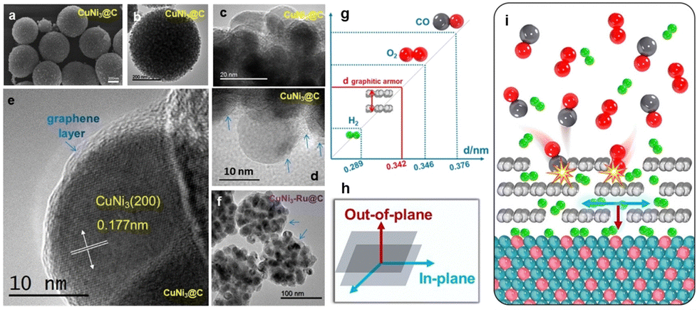 | ||
| Fig. 11 (a) SEM and (b)–(e) TEM images with different magnifications of CuNi3@C, (f) TEM image of CuNi3–Ru@C, (g) a comparison of the sizes of various molecules and the space between layers in a graphitic armor, (h) a diagram illustrating two directions in the graphitic carbon layer, and (i) CO and O2 cannot diffuse in the plane of the graphitic armor, while H2 can move both in-plane and out-of-plane.59 | ||
4. Conclusion and perspectives
While a solid–liquid interface in an electrochemical process has been the hotspot of research in electrochemistry, solid–solid heterogeneous interfaces exist universally in electrodes, which however somehow have been long overlooked compared to solid–liquid interfaces. In summary, this review or reflection of the various individual research examples in our group highlights the following three major aspects regarding the role of a solid–solid interface in electrocatalysis, and this can be enlightening for relevant researchers, especially beginners in this field:(a) The importance of a solid–solid interface in electrocatalysis shall be recognized: a solid–solid interface can form during the synthesis of an electrocatalyst (e.g., between the support and the active solid component), or preparation of an electrode (e.g., among the conductive carbon granules and the electrocatalyst particles, between the electrocatalyst layer and current collector). Efficient solid–solid interfacial interaction is necessary to ensure interfacial transfer of charge carriers as well as to guarantee long-term electrode integrity, especially when an electrochemical process is conducted in a chemically corrosive environment; interfacial electron delocalization at a solid–solid interface also provides an effective method to strategically modulate the local electronic structure and consequently the catalytic activity of the active sites.
(b) To achieve an extensive and intimate solid–solid interaction between two solids (which is often important for efficient electron transfer in electrocatalysis), our different research examples reveal that, at the meso-scale, the two interfaced solids shall have a large specific interfacial area, which sets requirement on the dimension of the two solids as well as on the way how they are being interfaced; at the micro-scale, a covalent solid–solid interface is preferred to achieve a strong interfacial interaction and a stable solid–solid interface, which requires careful tuning of the geometry as well the physicochemical properties of the surface atoms. This provides general guidelines and showcases to the readers how an efficient or optimal solid–solid interface shall be achieved in an electrocatalytic process.
(c) Last but not least, our research studies have also demonstrated the occurrence of the subtle interfacial electron delocalization phenomenon upon a solid–solid interface; how such an interfacial electronic interaction can modulate or even rewrite the physicochemical property of the electrocatalytic active sites during the electrochemical process has also been observed. Such a strong solid–solid interface electronic interaction, which thermodynamically shall be not easy, reveals the charm and potential of designing composite nanomaterials that leverage the unique properties of different components for realizing synergistic effects.
At the same time, while numerous research has demonstrated the importance and efficiency of solid–solid interfacial interactions in the electrocatalytic process, there are challenges when it comes to clarification of the structure–activity relationship. It's challenging to directly study the solid–solid interface because it's buried under a solid layer, which makes it hard to access. This makes it even more difficult to examine the electronic interactions happening at the interface. So far, we still have to rely on traditional ex situ or in situ characterization techniques such as SEM, TEM, AFM, XPS, XRD, and Raman spectroscopy. These methods, while useful for assessing the surface morphology, internal structure, and chemical states, often fall short when it comes to capturing the dynamic nature of solid–solid interfacial interactions which often locate underneath the reactive solid–liquid interface during reactions. The intricate three-dimensional architecture of these interfaces, coupled with their dynamic changes during electrochemical reactions, thus cannot be fully resolved using conventional techniques, thereby limiting our understanding of how these interfaces influence electrocatalytic performance.
Meanwhile, design of control samples is usually important for accurate comparison of electrocatalytic performance. An efficient control sample shall be able to support the so-called single-variable experiment. However, as the composite usually exists as nanomaterials, the design of efficient control samples is particularly challenging. It is often hard or even impossible to delicately change only one structural parameter (e.g., the thickness of the active solid) and at the same time not change the other structural features of the solid. Structural features such as the dimension, the surface structure, and the crystallinity of both solids might change at the same time when synthetic conditions are varied. The complexity of these systems, combined with the need to control multiple variables, makes it difficult to generate consistent and reproducible results. In this sense, data interpretation shall be cautioned.
At the current stage, to prove the interfacial electronic interaction, we often have to resort to DFT calculations, which, however, do not necessarily depict the real sample. This gap between the theoretical calculations and the real catalyst design is yet to be bridged. This also arouses concern on whether we can truly accomplish rational design of an efficient solid–solid interface, which requires simultaneous control over the solidification kinetics of not only one but two solids at both the atomic scale and the nanoscale. For instance, factors such as the contact tightness between particles, variations in work function, and the arrangement of atoms at the interface all impact the interface integrity. Hence, the controllable construction of heterogeneous interfaces also poses technical challenges. Developing methods to precisely regulate the composition and structure of solid–solid interfaces, particularly to achieve synergistic effects in actual electrode materials, is an area that still requires significant advancement.
Moving forward, overcoming these obstacles will require a concerted effort in interfacial engineering: the development of new advanced characterization techniques and innovative material design strategies. By addressing these limitations, researchers can unlock the full potential of solid–solid interfaces, further enhancing their role in advancing the efficiency and effectiveness of electrochemical catalytic systems.
Author contributions
Wen-Xuan Liang: writing – original draft, formal analysis, and visualization; Huimin Han: writing – original draft, formal analysis, and visualization; Chun-Hua Zhen: project administration and supervision; Yingjie Hua: project administration and supervision; Jun-Tao Li: conceptualization, funding acquisition, and resources; and Yao Zhou: conceptualization, funding acquisition, resources, project administration, supervision, and writing – review and editing.Data availability
No primary research results, software or codes were included and no new data were generated or analysed as part of this review.Conflicts of interest
There are no conflicts to declare.Acknowledgements
The National Key Research and Development Program of China (no. 2022YFA1505300), the National Natural Science Foundation of China (no. 22072124, 22472142, 22288102), and the Natural Science Foundation of Fujian Province, China (no. 2024J09010) were acknowledged.Notes and references
- Z. W. Seh, J. Kibsgaard, C. F. Dickens, I. Chorkendorff, J. K. Nørskov and T. F. Jaramillo, Science, 2017, 355, eaad4998 CrossRef PubMed
.
- J. Kang, X. Yang, Q. Hu, Z. Cai, L.-M. Liu and L. Guo, Chem. Rev., 2023, 123, 8859–8941 CrossRef CAS PubMed
- J. Wu and Y.-X. Yu, Int. J. Hydrogen Energy, 2023, 48, 5961–5975 CrossRef CAS
- J. Wu and Y.-X. Yu, J. Phys. Chem. C, 2022, 126, 12460–12471 CrossRef CAS
- T. X. Nguyen, Z.-Y. Wei, T.-M. Zheng, Y.-H. Su, K.-S. Chuang and J.-M. Ting, Chem. Eng. J., 2024, 496, 153841 CrossRef CAS
- S. Samira, S. Deshpande, J. Greeley and E. Nikolla, ACS Energy Lett., 2021, 6, 665–674 CrossRef CAS
- Q. Lu, X. Zou, Y. Bu and Z. Shao, Energy Storage Mater., 2023, 55, 166–192 CrossRef
- Y. Cheng and S. P. Jiang, Prog. Nat. Sci.: Mater. Int., 2015, 25, 545–553 CrossRef CAS
- X. Long, J. Li, S. Xiao, K. Yan, Z. Wang, H. Chen and S. Yang, Angew. Chem., Int. Ed., 2014, 53, 7584–7588 CrossRef CAS PubMed
- K. Wei, X. Wang and J. Ge, Chem. Soc. Rev., 2024, 53, 8903–8948 RSC
- J. Li, R. Güttinger, R. Moré, F. Song, W. Wan and G. R. Patzke, Chem. Soc. Rev., 2017, 46, 6124–6147 RSC
- W. Zhao, S. Yuan, L. Zhang, F. Jiang, Y. Yang, G. Zou, H. Hou, P. Ge, W. Sun and X. Ji, Energy Storage Mater., 2022, 45, 1183–1200 CrossRef
- X. Cheng, Y. Li, L. Zheng, Y. Yan, Y. Zhang, G. Chen, S. Sun and J. Zhang, Energy Environ. Sci., 2017, 10, 2450–2458 RSC
- T. Zhu, S. Liu, B. Huang, Q. Shao, M. Wang, F. Li, X. Tan, Y. Pi, S.-C. Weng, B. Huang, Z. Hu, J. Wu, Y. Qian and X. Huang, Energy Environ. Sci., 2021, 14, 3194–3202 RSC
- F. Luo, P. Yu, J. Xiang, J. Jiang and S. Chen, J. Energy Chem., 2024, 94, 508–516 CrossRef CAS
- K. Ham, J. Lee, K. Lee and J. Lee, J. Energy Chem., 2022, 71, 580–587 CrossRef CAS
- Z. J. Xu, Nano-Micro Lett., 2017, 10, 8 CrossRef PubMed
- P. Liu, A. Klyushin, P. Chandramathy Surendran, A. Fedorov, W. Xie, C. Zeng and X. Huang, ACS Nano, 2023, 17, 24395–24403 CrossRef CAS PubMed
- R. G. Rao, R. Blume, T. W. Hansen, E. Fuentes, K. Dreyer, S. Moldovan, O. Ersen, D. D. Hibbitts, Y. J. Chabal, R. Schlögl and J.-P. Tessonnier, Nat. Commun., 2017, 8, 340 CrossRef PubMed
- J. M. Kim, Y. J. Lee, S.-H. Kim, K.-H. Chae, K. R. Yoon, K. A. Lee, A. Byeon, Y. S. Kang, H.-Y. Park, M. K. Cho, H. C. Ham and J. Y. Kim, Nano Energy, 2019, 65, 104008 CrossRef CAS
- Y. Zhou, W. Yuan, M. Li, Z. Xie, X. Song, Y. Yang, J. Wang, L. Li, W. Ding, W.-F. Lin and Z. Wei, Nat. Energy, 2024, 9, 1297–1309 CrossRef CAS
- A. Wang, M. Du, J. Ni, D. Liu, Y. Pan, X. Liang, D. Liu, J. Ma, J. Wang and W. Wang, Nat. Commun., 2023, 14, 6733 CrossRef CAS PubMed
- P.-F. Zhang, J.-H. Li, S.-J. Zhang, D.-C. Li, S.-Y. Zeng, S.-L. Xu, Q.-X. Yao, L.-Y. Liu, L. Ding, H.-X. Li, Y.-Y. Hu, J.-T. Li and Y. Zhou, Adv. Funct. Mater., 2024, 34, 2306359 CrossRef CAS
- Q. Liang, J. Chen, Y. Zhou, J.-T. Li, L. Huang and S.-G. Sun, Adv. Funct. Mater., 2021, 31, 2104513 CrossRef CAS
- Z. Tong, C. Lv, Y. Zhou, Z.-W. Yin, Z.-P. Wu and J.-T. Li, Energy Storage Mater., 2024, 67, 103301 CrossRef
- P.-F. Zhang, Y.-Y. Hu, X.-Y. Cui, J.-H. Li, S.-Y. Zeng, J. Li, H.-G. Hao, X.-J. Kong, Y. Zhou and J.-T. Li, Mater. Today Phys., 2024, 40, 101307 CrossRef CAS
- H. Wang, L. Xu, Y. Bai and Z. L. Wang, Nat. Commun., 2020, 11, 4203 CrossRef PubMed
- K. Mustonen, A. Hussain, C. Hofer, M. R. A. Monazam, R. Mirzayev, K. Elibol, P. Laiho, C. Mangler, H. Jiang, T. Susi, E. I. Kauppinen, J. Kotakoski and J. C. Meyer, ACS Nano, 2018, 12, 8512–8519 CrossRef CAS PubMed
- X. Su, K. Guo, T. Ma, P. A. Tamirisa, H. Ye, H. Gao and B. W. Sheldon, ACS Energy Lett., 2017, 2, 1729–1733 CrossRef CAS
- Y. Zhou and H. C. Zeng, J. Phys. Chem. C, 2016, 120, 29348–29357 CrossRef CAS
- J. Zhang, J.-J. Dai, D.-Q. Cao, H. Xu, X.-Y. Ding, C.-H. Zhen, B. Paulus, J.-Y. Ye, Q. Liang, J.-K. Liu, S.-J. Xie, S.-S. Deng, Z. Wang, J.-T. Li, Y. Zhou and S.-G. Sun, J. Energy Chem., 2023, 83, 313–323 CrossRef CAS
- P.-F. Zhang, J.-Y. Zhang, T. Sheng, Y.-Q. Lu, Z.-W. Yin, Y.-Y. Li, X.-X. Peng, Y. Zhou, J.-T. Li, Y.-J. Wu, J.-X. Lin, B.-B. Xu, X.-M. Qu, L. Huang and S.-G. Sun, ACS Catal., 2020, 10, 1640–1651 CrossRef CAS
- P.-F. Zhang, T. Sheng, Y. Zhou, Y.-J. Wu, C.-C. Xiang, J.-X. Lin, Y.-Y. Li, J.-T. Li, L. Huang and S.-G. Sun, Chem. Eng. J., 2022, 448, 137541 CrossRef CAS
- P.-F. Zhang, Y.-Q. Lu, Y.-J. Wu, Z.-W. Yin, J.-T. Li, Y. Zhou, Y.-H. Hong, Y.-Y. Li, L. Huang and S.-G. Sun, Chem. Eng. J., 2019, 363, 224–233 CrossRef CAS
- Z. Wang, L. Deng, X.-R. Yang, J.-X. Lin, D.-Q. Cao, J.-K. Liu, Z. Tong, J. Zhang, G.-Y. Bai, Y.-X. Luo, Z.-W. Yin, Y. Zhou and J.-T. Li, Adv. Funct. Mater., 2024, 34, 2404137 CrossRef CAS
- D. N. Basov, M. M. Fogler and F. J. García de Abajo, Science, 2016, 354, aag1992 CrossRef PubMed
- Y. Liu, Y. Huang and X. Duan, Nature, 2019, 567, 323–333 CrossRef CAS PubMed
- H. Xu, S.-J. Xie, C. Lv, J.-T. Li, Y. Zhou and S.-G. Sun, J. Mater. Chem. A, 2023, 11, 10277–10286 RSC
- K. Carter-Fenk and J. M. Herbert, Phys. Chem. Chem. Phys., 2020, 22, 24870–24886 RSC
- W. Hao, B. Guo, J. Liu, Q. Ren, S. Li, Q. Li, K. Zhou, L. Liu and H.-C. Wu, J. Am. Chem. Soc., 2024, 146, 10206–10216 CrossRef CAS PubMed
- Z. Liu, T. Lu and Q. Chen, Carbon, 2021, 171, 514–523 CrossRef CAS
- Y. Chen, J. Ma, Q. Peng, X. Gong, J. Lin, X. Qi and H. Guo, ACS Appl. Mater. Interfaces, 2022, 14, 20896–20906 CrossRef CAS PubMed
- L. Pauling, J. Am. Chem. Soc., 1935, 57, 2680–2684 CrossRef CAS
- M. Ekimova, C. Kleine, J. Ludwig, M. Ochmann, T. E. G. Agrenius, E. Kozari, D. Pines, E. Pines, N. Huse, P. Wernet, M. Odelius and E. T. J. Nibbering, Angew. Chem., Int. Ed., 2022, 61, e202211066 CrossRef CAS PubMed
- C. Guhl, J. Rohrer, P. Kehne, T. Ferber, L. Alff, K. Albe, W. Jaegermann, P. Komissinskiy and R. Hausbrand, Energy Storage Mater., 2021, 37, 190–198 CrossRef
- J. Chen, F. Zheng, S.-J. Zhang, A. Fisher, Y. Zhou, Z. Wang, Y. Li, B.-B. Xu, J.-T. Li and S.-G. Sun, ACS Catal., 2018, 8, 11342–11351 CrossRef CAS
- Y.-J. Wu, J. Yang, T.-X. Tu, W.-Q. Li, P.-F. Zhang, Y. Zhou, J.-F. Li, J.-T. Li and S.-G. Sun, Angew. Chem., Int. Ed., 2021, 60, 26829–26836 CrossRef CAS PubMed
- Y. Zhou and H. C. Zeng, ACS Sustainable Chem. Eng., 2019, 7, 5953–5962 CrossRef CAS
- C. Wagner, J. Phys. Chem. Solids, 1972, 33, 1051–1059 CrossRef CAS
- Z. Zhang and J. T. Yates, Jr., Chem. Rev., 2012, 112, 5520–5551 CrossRef CAS PubMed
- S. Jia, H. Han, B. Wang, J. Liu, Q. Tang, G. Liu, Q. Ruan, X. Zhu, H. Li, C. Wang, P. K. Chu and Y. Hua, Appl. Catal., B, 2024, 353, 124050 CrossRef CAS
- S. Sun, R. Gao, X. Liu, L. Pan, C. Shi, Z. Jiang, X. Zhang and J.-J. Zou, Sci. Bull., 2022, 67, 389–397 CrossRef CAS PubMed
- W. Li, C. Liu, C. Gu, J.-H. Choi, S. Wang and J. Jiang, J. Am. Chem. Soc., 2023, 145, 4774–4783 CrossRef CAS PubMed
- B. Wang, H. Chen, W. Zhang, H. Liu, Z. Zheng, F. Huang, J. Liu, G. Liu, X. Yan, Y.-X. Weng, H. Li, Y. She, P. K. Chu and J. Xia, Adv. Mater., 2024, 36, 2312676 CrossRef CAS PubMed
- Y.-J. Wu, X.-H. Wu, T.-X. Tu, P.-F. Zhang, J.-T. Li, Y. Zhou, L. Huang and S.-G. Sun, Appl. Catal., B, 2020, 278, 119259 CrossRef CAS
- L. Yu, D. Deng and X. Bao, Angew. Chem., Int. Ed., 2020, 59, 15294–15297 CrossRef CAS PubMed
- Y. Song, X. Yang, H. Liu, S. Liang, Y. Cai, W. Yang, K. Zhu, L. Yu, X. Cui and D. Deng, J. Am. Chem. Soc., 2024, 146, 5834–5842 CrossRef CAS PubMed
- Q. Liang, Y. Zhao, J.-D. Chen, J.-J. Dai, X. Ding, Z. Tong, S.-J. Xie, J. Zhang, Z.-H. Zhou, J.-T. Li, J.-F. Li and Y. Zhou, Chem. Mater., 2022, 34, 5607–5620 CrossRef CAS
- H.-W. Chen, D.-Q. Cao, S.-J. Xie, J.-J. Dai, Z.-H. Dai, C.-H. Zhen, J.-F. Li, B. Paulus, Z.-W. Yin, J.-T. Li, Y. Zhou and S.-G. Sun, Angew. Chem., Int. Ed., 2024, 63, e202317922 CrossRef CAS PubMed
Footnote |
| † These authors contributed equally to this work. |
| This journal is © The Royal Society of Chemistry 2024 |