 Open Access Article
Creative Commons Attribution 3.0 Unported Licence
Combining radial and continuous flow synthesis to optimize and scale-up the production of medicines†
Mara
Guidi
 ab,
Sooyeon
Moon
 ab,
Lucia
Anghileri
ab,
Dario
Cambié
ab,
Lucia
Anghileri
ab,
Dario
Cambié
 a,
Peter H.
Seeberger
 *ab and
Kerry
Gilmore
 *ac
*ac
aDepartment of Biomolecular Systems, Max Planck Institute of Colloids and Interfaces, Am Mühlenberg 1, 14476 Potsdam, Germany. E-mail: peter.seeberger@mpikg.mpg.de
bDepartment of Chemistry and Biochemistry, Freie Universität Berlin, Arnimallee 22, 14195 Berlin, Germany
cUniversity of Connecticut, Storrs, CT 06269, USA. E-mail: kerry.m.gilmore@uconn.edu
First published on 5th January 2021
Abstract
Current drug production in batch cannot adapt rapidly to market demands, evidenced by recent shortages in many markets globally of essential medicines. Flow chemistry is a valuable tool for on-demand production of active pharmaceutical ingredients (APIs). Here, we reveal a new concept to develop and produce APIs, where an automated synthesizer that works with discrete volumes of solutions is employed at the discovery stage to identify the optimal synthetic route and conditions before a commercially available continuous flow system is used for scale-up. This concept is illustrated by the synthesis of nifedipine and paracetamol, in short supply in Germany during the COVID-19 pandemic, and the local anesthetic lidocaine.
Drug production is a space and time-consuming process. Today, the primary manufacturing, i.e. the production of an active pharmaceutical ingredient (API), is often outsourced to a contract manufacturing organization (CMO) and performed in locations that are geographically separate from the secondary manufacturing, i.e. the formulation of the final dosage form.9 This presents problems when needs suddenly fluctuate due to the lack of rapid flexibility – a challenge intricately linked to the discontinuous batch mode of operation that protracts production times to several months.
Batch manufacturing suffers from the need for large equipment and difficulties in reaction scale-up. Therefore, pharmaceutical production in a country cannot be adapted immediately to its needs. Flow chemistry is an attractive alternative process to overcome the space–time–cost issues related to the batch production of pharmaceuticals, as continuous flow processes can be carried out using compact systems and are readily scalable.2–4,6
On-demand production can help avoid drug shortages compensating for unexpected fluctuations in API availability.1 Flow processes not only facilitate scale-up, but ensure reproducibility while transferring the synthesis from the discovery to the production stage.
Automated synthesizers incorporating continuous flow techniques have been developed for on-demand API production,5,10,11 and these modular reconfigurable systems are now supported by artificial intelligence for retrosynthesis planning and robotics for the physical reconfiguration of the system between syntheses.5 An alternative approach relies not on automated reconfigurability, but on radially arranged, equally accessible flow reactors in an automated system capable of sequential, non-simultaneous processes. The conditions of each step within a radial synthesis are functionally independent, and reactors can be reused under different conditions – allowing for facile and rapid screenings, optimization (of single- or multistep processes), and synthesis of both linear and convergent pathways.7 The radial synthesizer is optimal for the discovery stage of the synthetic process and does not require physical reconfiguration of the instrument between processes. It is made from commercially available equipment and the automation software is freely available.7
Continuous flow protocols can be readily transferred to radial flow.7 Here, we show that the conditions optimized during reaction development on the radial synthesizer (temperature, pressure, concentration, stoichiometry, solvent, and residence time) are readily translated to a commercial continuous flow system for scale-up. To illustrate the importance of rapid access to convenient routes to APIs and their rapid scale-up, we selected paracetamol (1) and nifedipine (2), two APIs that were in short supply in several European countries8 during the COVID-19 pandemic, as well as the synthesis of lidocaine (3) that was in shortage in Sweden8 and is often in short supply in Canada12 (Fig. 1a).
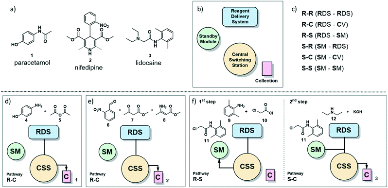 | ||
| Fig. 1 a) The painkiller paracetamol (1), the hypertension drug nifedipine (2) and the local anesthetic lidocaine (3) are on the WHO list of essential drugs.13 b) Main sections of the radial synthesizer: reagent delivery system (RDS), central switching station (CSS), standby module (SM) and collection vessels (C). c) Six pathways of solution flow through the instrument are described by the starting location of the reagents and their destination. For example, R–C refers to a solution starting in the RDS and ending in the collection vessel. d) Reagents and pathway for the radial synthesis of paracetamol (1). e) Reagents and pathway for the radial synthesis of nifedipine (2). f) Reagents and pathways for the radial synthesis of lidocaine (3). | ||
Radial synthesizer
The radial synthesizer7 (Fig. 1b) is composed by four main sections: the reagent delivery system (RDS) where reagents are mixed and added to the reaction, the central switching station (CSS) that connects to all reactors; the standby module (SM) for intermediate storage, and the collection vessels (C). These four sections are accessible by the flowing solution via six main pathways, defined by the starting point and destination of the reagent stream (Fig. 1c). Each pathway proceeds through the CSS and the chosen reactor at the conditions set.For single step syntheses such as paracetamol (1) and nifedipine (2) (Fig. 1d and e, respectively), the solution flows from the RDS, through the CSS, and is sent to a collection vessel (C) for purification or analysis (termed the R–C path).
For multistep syntheses, such as for lidocaine (3) (Fig. 1f), the solution coming from the RDS in the first step will proceed to the SM (R–S path) for intermediate storage. In the second step, this intermediate solution (stored in the SM) is mixed with additional reagents coming from the RDS and collected (S–C path).
The chemical transformations of the three syntheses described here are performed either at room or elevated temperature. All of these transformations are performed using the same PFA 10 mL coil reactor, as temperature and flow rate can be set independently for each synthetic step. The latter allows for different residence times can be achieved within the same 10 mL reactor. Long residence times can be achieved using the stop-flow mode, a function of the radial synthesizer that seals the reaction mixture inside a specific module by diverting the carrier gas stream through different ports of the CSS.
Synthesis of paracetamol (1)
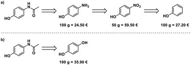
Paracetamol, a commonly used and inexpensive painkiller, was in short supply in Germany during the COVID-19 pandemic in early 2020.8 Aiming at developing a scalable process for the production of paracetamol from starting materials available in Europe, we evaluated the possible starting points for the synthesis. Phenol,14 4-nitrophenol,15 and 4-aminophenol16 can serve as starting materials. 4-Aminophenol is the most cost-efficient starting material (Fig. 2a). An alternative route starts from hydroquinone and uses ammonium acetate for para-aminophenol formation and acetylation17 (Fig. 2b), but this is more expensive than the simple acetylation of 4-aminophenol.Optimization of the synthesis of 1 in the radial synthesizer
A solution of 4-aminophenol (4) in a mixture of water/acetic acid (4![[thin space (1/6-em)]](https://www.rsc.org/images/entities/char_2009.gif) :
:![[thin space (1/6-em)]](https://www.rsc.org/images/entities/char_2009.gif) 1, 2 M) and neat acetic anhydride (5) were placed in the reagent delivery system (RDS) of the radial synthesizer. Screening of temperature and residence time were performed selecting the R–C pathway, using 0.5 mL of each reagent solution per experiment (Fig. 1d, see ESI† for details).
1, 2 M) and neat acetic anhydride (5) were placed in the reagent delivery system (RDS) of the radial synthesizer. Screening of temperature and residence time were performed selecting the R–C pathway, using 0.5 mL of each reagent solution per experiment (Fig. 1d, see ESI† for details).
The reaction proceeded smoothly in five minutes at room temperature with no precipitation observed when using neat acetic anhydride (5). Rapid screening of the reaction stoichiometry revealed that direct product crystallization begins sooner when fewer equivalents of acetic anhydride are employed. Paracetamol crystallizes ten minutes after addition when working with three equivalents of 5.
Scale up of the synthesis of 1 in continuous flow
This process was scaled up feeding a solution of 4 in water/acetic acid (4![[thin space (1/6-em)]](https://www.rsc.org/images/entities/char_2009.gif) :
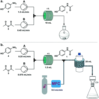
:![[thin space (1/6-em)]](https://www.rsc.org/images/entities/char_2009.gif) 1; 2 M) from pump A and neat acetic anhydride (5) from pump B. When a 10 mL coil reactor was used, the two feeds were set at 1.5 and 0.45 mL min−1 respectively to achieve the optimized five minute residence time, and the resulting solution was collected upon reaction in a flask and stirred at room temperature for 1 h. Running the system for 15 minutes we achieved 6.36 g of crystallized 1 (94% yield) (Fig. 3a). Productivity for this process was 25.6 g h−1, translating to 1229 doses per day (see electronic supplementary information for productivity calculations).
1; 2 M) from pump A and neat acetic anhydride (5) from pump B. When a 10 mL coil reactor was used, the two feeds were set at 1.5 and 0.45 mL min−1 respectively to achieve the optimized five minute residence time, and the resulting solution was collected upon reaction in a flask and stirred at room temperature for 1 h. Running the system for 15 minutes we achieved 6.36 g of crystallized 1 (94% yield) (Fig. 3a). Productivity for this process was 25.6 g h−1, translating to 1229 doses per day (see electronic supplementary information for productivity calculations).
The occurrence of spontaneous crystallization after reaction completion presents the opportunity for a telescoped in-line crystallization module (Fig. 3b). This module was based on the SMBR (serial micro-batch reactors) technique18 that generates a segmented flow, spaced by nitrogen gas, to efficiently transport heterogeneous material in flow. Crystallization occurs in droplets and the slurry exiting the telescoped process is directly filtered, providing pure crystals of paracetamol. To achieve a sufficient residence time (30 min) in the crystallization module (20 mL, i.d. 1.6 mm PFA coil around a 1 L glass bottle at 25 °C), the size of the reactor coil was decreased from 10 mL to 1.5 mL and the flow rates to 0.25 mL min−1 and 0.075 mL min−1, respectively, for pumps A and B. The N2 flow rate was set at 0.5 mL min−1. Collecting for 15 minutes on the filter resulted in 634 mg of paracetamol (56%). Longer crystallization times (1 h) were achieved by doubling the length of the crystallization module. While this resulted in a significant increase in crystallization yield (93%), process instability due to aggregation issues within the droplets was also observed. Lower temperatures for the crystallization module did not have an impact on yield.
Synthesis of nifedipine (2)
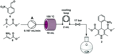
Nifedipine is used to treat angina and hypertension19 and was in short supply in Germany during the COVID-19 pandemic. Nifedipine is synthesized in batch through a one-step multicomponent reaction mixing 2-nitrobenzaldehyde 6, methyl acetoacetate 7, and methyl 3-aminocrotonate 8 at elevated temperatures in alcohol solvents for several hours.20–22In an effort to accelerate the reaction, temperatures from 90 °C to 150 °C, and residence times between 5 and 90 min were investigated. The reaction time decreased with increasing temperature and the best yield was achieved at a 60 min residence time – using stop-flow mode – at 150 °C.
Synthesis of lidocaine (3)
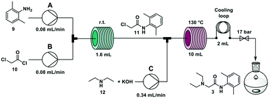
The widely employed local anaesthetic23 lidocaine is produced via a two-step process. In the first step, 2,6-dimethyl aniline 9 reacts with chloroacetyl chloride 10 to give 2-chloro-N-(2,6-dimethylphenyl)acetamide 11. In the second step, diethylamine 12 substitutes the chlorine atom yielding the final product. Several flow syntheses of lidocaine have been reported,5,10,24,25 including on automated synthesizers.5,10,24A second step was coupled using the overall R–S + S–C pathway. Two new solutions were loaded in the RDS: a solution of KOH (0.6 M in methanol/water 1![[thin space (1/6-em)]](https://www.rsc.org/images/entities/char_2009.gif) :
:![[thin space (1/6-em)]](https://www.rsc.org/images/entities/char_2009.gif) 1) and a solution of diethylamine 12 (1.5 M in methanol/water 1
1) and a solution of diethylamine 12 (1.5 M in methanol/water 1![[thin space (1/6-em)]](https://www.rsc.org/images/entities/char_2009.gif) :
:![[thin space (1/6-em)]](https://www.rsc.org/images/entities/char_2009.gif) 1) and were mixed with the reaction mixture of the first step containing intermediate 11 delivered from the standby module (Fig. 1f). The crude reaction mixture exited the synthesizer and was extracted offline with hexane and NH4Cl/NaCl (1
1) and were mixed with the reaction mixture of the first step containing intermediate 11 delivered from the standby module (Fig. 1f). The crude reaction mixture exited the synthesizer and was extracted offline with hexane and NH4Cl/NaCl (1![[thin space (1/6-em)]](https://www.rsc.org/images/entities/char_2009.gif) :
:![[thin space (1/6-em)]](https://www.rsc.org/images/entities/char_2009.gif) 1) and crystallized as the hydrochloride salt (see ESI†). The highest overall yield (62%) is achieved when the second step is performed with a residence time of 20 minutes at 130 °C, in agreement with previous literature reports.5,10
1) and crystallized as the hydrochloride salt (see ESI†). The highest overall yield (62%) is achieved when the second step is performed with a residence time of 20 minutes at 130 °C, in agreement with previous literature reports.5,10
![[thin space (1/6-em)]](https://www.rsc.org/images/entities/char_2009.gif) :
:![[thin space (1/6-em)]](https://www.rsc.org/images/entities/char_2009.gif) 1 at 0.34 mL min−1 (total flow rate 0.5 mL min−1) through a 10 mL stainless steel coil heated at 130 °C (residence time = 20 min) (Fig. 5). The crude reaction mixture was collected for 90 minutes (45 mL) and was extracted offline with hexane and NH4Cl/NaCl (1
1 at 0.34 mL min−1 (total flow rate 0.5 mL min−1) through a 10 mL stainless steel coil heated at 130 °C (residence time = 20 min) (Fig. 5). The crude reaction mixture was collected for 90 minutes (45 mL) and was extracted offline with hexane and NH4Cl/NaCl (1![[thin space (1/6-em)]](https://www.rsc.org/images/entities/char_2009.gif) :
:![[thin space (1/6-em)]](https://www.rsc.org/images/entities/char_2009.gif) 1) to obtain 1.15 g of lidocaine hydrochloride after crystallization (59% yield). Productivity for this process was 0.8 g h−1 that translates to 19.2 g per day (see ESI† for productivity calculations).
1) to obtain 1.15 g of lidocaine hydrochloride after crystallization (59% yield). Productivity for this process was 0.8 g h−1 that translates to 19.2 g per day (see ESI† for productivity calculations).
Conclusions
In summary, the flexibility and responsiveness of pharmaceutical production needs to be significantly increased. In light of the recent global disruptions to the current distributed supply chains, as well as the heavy reliance on CMOs, an alternative approach is needed. Using a highly flexible automated flow chemistry platform such as a radial synthesizer, reproducible API syntheses can rapidly be adapted or developed. Herein we have shown the conditions developed and optimized on the radial synthesizer are readily transferred to a dedicated continuous flow system for scale up. Processes were developed for three WHO essential medicines that have been in short supply during the COVID-19 pandemic: paracetamol, lidocaine, and (for the first time in flow) nifedipine.Author contributions
M. G., S. M., L. A. and D. C. performed the experiments. M. G. wrote the draft of the manuscript, and all authors participated in revising the manuscript. P. H. S. and K. G. provided oversight to the project and secured funding.Conflicts of interest
There are no conflicts to declare.Acknowledgements
Open Access funding provided by the Max Planck Society.Notes and references
- S. Vogler and S. Fischer, Health policy, 2020, 124, 1287–1296, DOI:10.1016/j.healthpol.2020.09.001.
- F. Ferlin, D. Lanari and L. Vaccaro, Green Chem., 2020, 22, 5937–5955 RSC.
- M. B. Plutschack, B. Pieber, K. Gilmore and P. H. Seeberger, Chem. Rev., 2017, 117, 11796–11893 CrossRef CAS.
- M. Trobe and M. D. Burke, Angew. Chem., Int. Ed., 2018, 57, 4192–4214 CrossRef CAS.
- C. W. Coley, A. D. A. Thomas III, J. A. M. Lummiss, J. N. Jaworski, C. P. Breen and V. Schultz, et al. , Science, 2019, 365, 6453, DOI:10.1126/science.aax1566.
- V. R. L. J. Bloemendal, M. A. C. H. Janssen, J. C. M. van Hest and F. P. J. T. Rutjes, React. Chem. Eng., 2020, 5, 1186–1197 RSC.
- S. Chatterjee, M. Guidi, P. H. Seeberger and K. Gilmore, Nature, 2020, 579, 379–384 CrossRef CAS.
- See ESI† for the list of shortages of paracetamol, nifedipine and lidocaine in European countries .
- N. Shah, Comput. Chem. Eng., 2004, 28, 929–941 CrossRef CAS.
- A. Adamo, R. L. Beingessner, M. Behnam, J. Chen, T. F. Jamison, K. F. Jensen and J.-C. M. Monbaliu, et al. , Science, 2016, 352, 61–67 CrossRef CAS.
- P. Zhang, N. Weeranoppanant, D. A. Thomas, K. Tahara, T. Stelzer, M. G. Russell and M. O'Mahony, et al. , Chem. – Eur. J., 2018, 24, 2776–2784 CrossRef CAS.
- Report of drug shortages and discontinuations in Canada: https://www.drugshortagescanada.ca/.
- Paracetamol, Lidocaine and Nifedipine are in the WHO list of essential drugs: https://apps.who.int/iris/bitstream/handle/10665/325771/WHO-MVP-EMP-IAU-2019.06-eng.pdf?sequence=1&isAllowed=y.
- J. Ralph, S. Karlen and J. Mobley, US10286504B2, Wisconsin Alumni Research Foundation, 2018.
- J. Huber, Jr., US4264525A, Penick Corporation, 1979.
- M. Sato, K. Matsushima, H. Kawanami, M. Chatterjee, T. Yokoyama, Y. Ikuhsima and T. M. Suzuki, Lab Chip, 2009, 9, 2877–2880 RSC.
- M. L. Lemaire, R. Joncour, N. F. D. Duguet, E. C. D. Metay and A. Ferreira, EP2860172A1, Minakem, 2015.
- B. Pieber, M. Shalom, M. Antonietti, P. H. Seeberger and K. Gilmore, Angew. Chem., Int. Ed., 2018, 57, 9976–9979 CrossRef CAS.
- Nifedipine is a dihydropyridine derivative and a calcium-channel blocking agent used to treat several diseases:https://www.drugs.com/monograph/nifedipine.html.
- M. Filipan-Litvić, M. Litvić, I. Cepanec and V. Vinković, Molecules, 2007, 12, 2546–2558 CrossRef.
- M. Berwe, H. Diehl, K. Rittner, K. Wahl and H. Wirges, US6294673B1, Bayer Aktiengesellschaft, 2001.
- P. T. Baraldi, T. Noël, Q. Wang and V. Hessel, Tetrahedron Lett., 2014, 55, 2090–2092 CrossRef CAS.
- H. Hermann, M. W. Hollmann, M. F. Stevens, P. Lirk, T. Brandenburger, T. Piegeler and R. Werdehausen, Br. J. Anaesth., 2019, 123, 335–349 CrossRef.
- J. Britton, J. M. Chalker and C. L. Raston, Chem. – Eur. J., 2015, 21, 10660–10665 CrossRef CAS.
- S. H. M. Mehr, M. Craven, A. I. Leonov, G. Keenan and L. Cronin, Science, 2020, 370, 101–108 CrossRef CAS.
Footnote |
| † Electronic supplementary information (ESI) available. See DOI: 10.1039/d0re00445f |
| This journal is © The Royal Society of Chemistry 2021 |

