
Controllable graphene coated mesoporous carbon/sulfur composite for lithium–sulfur batteries†
Shanliang Chen,
Qunli Tang*,
Xiaohua Chen*,
Aiping Hu,
Weina Deng and
Zheng Liu
College of Materials Science and Engineering, Hunan University, Hunan Province Key Laboratory for Spray Deposition Technology and Application, Changsha 410082, China. E-mail: tangqunli@hnu.edu.cn; xiaohuachen@hnu.edu.cn; Fax: +86 73188823554; Tel: +86 73188821610
First published on 21st August 2015
Abstract
Lithium–sulfur (Li–S) batteries are attractive for the next generation of rechargeable batteries due to their high energy density, but several problems have hindered their widespread practical realization. Mesoporous carbon/sulfur (CMK-3/S) composites, controllably coated with graphene sheets via the functionalization of the CMK-3 surface with the assistance of a bridging agent (L-lysine and PEG), are presented here. Scanning electron microscopy (SEM) and transmission electron microscopy (TEM) demonstrated that the graphene could be coated uniformly and tightly on the surface of mesoporous carbon/sulfur (RGO@CMK-3/S) particles in the presence of L-lysine. In this unique “double-carbon” structure, the abundant pore structure and graphene coating layers serve to accommodate the large volume expansion of the sulfur nanoparticles during discharge, preventing the dissolution of polysulfide intermediates from the cathode, and improving the sulfur nanoparticles’ electrical conductivity. Galvanostatic charge–discharge tests indicated that the RGO@CMK-3/S composite prepared using L-lysine exhibited high and stable specific capacities of up to ∼720 mA h g−1 over more than 100 cycles at 0.5C, and an excellent rate capability of 660 mA h g−1 at a rate of 2C, representing a promising cathode material for rechargeable lithium batteries.
Introduction
Recently, high-performance batteries with high energy densities and longer cycling life have attracted great interest due to the demands for portable electronic devices, and as alternative energy sources for electric vehicles (EVs) and hybrid electric vehicles (HEVs).1 However, the low energy density of the current cathode materials, such as LiCoO2, LiMn2O4 and LiFePO4 etc., makes it difficult to meet the requirements. Therefore, a considerable amount of effort has recently been focused on high energy density rechargeable batteries,2–4 which is related to the development of high capacity cathode materials. Among the various cathode materials, sulphur is a promising candidate for the next generation of cathodes because of its high theoretical specific capacity of 1675 mA h g−1, non-toxicity, low price and the abundance of raw materials.5 Unfortunately, sulfur as a cathode material is plagued with many problems that have hindered its widespread practical realization, including low intrinsic electrical conductivity (conductivity ≈ 5 × 10–30 S cm−1), dissolution of polysulfides in electrolyte, and large volume expansion.6,7 The low intrinsic electrical conductivity and volume expansion lead to low use of the active material. The dissolution of lithium polysulfides (Li2Sn, 2 < n ≤ 8) and the action of their notorious “shuttle effect” cause the rapid fading of the active materials and make the Li metal–electrolyte interface become unstable, both of which play critical roles in severe capacity decay.8,9 Extensive efforts have been devoted to overcoming these problems, by encapsulating sulphur particles with conducting materials, including porous carbon,10–12 carbon nanotubes,7,13 graphene14–18 and conductive polymer matrices.19,20 Among these efforts, mesoporous carbon has received plenty of attention because of its small pore size and larger overall pore volume, which can mitigate the dissolution of lithium polysulfides and buffer the large volume change of sulfur. However, the dissolution of polysulfides could only be mitigated, but not eliminated.6,15 One of the most popular approaches to prevent the outflow of polysulfides from the channels is to modify the porous channels or the appearance of the mesoporous carbon.Graphene is one of the most favorable carbonaceous materials due to its two-dimensional nanostructure with high surface area (over 2600 m2 g−1), outstanding conductivity, superior structural flexibility and mechanical strength.21 Lately, graphene as a novel and highly conductive nanocarbon component has been successfully applied in lithium–sulfur battery cathode materials,6,14,22 and the resulting electrodes have exhibited an improvement in cycling stability and rate performance. In these electrodes, the graphene was expected to uniformly and tightly coat the surface of sulfur particles for restricted diffusion of polysulfides and buffer the large volume expansion effects. However, it is difficult for the graphene to tightly wrap the surface of sulfur or other particles due to its two-dimensional sheet nature, resulting in only a restricted enhancement in the electrochemical performance of Li–S batteries.23 Recently, various approaches have been reported to construct a graphene coated CMK-3/S composite, but most of the present systems have no intimate contact between the graphene and CMK-3/S particles. This may be ascribed to the inertness of the CMK-3 surface and the unmatched “plane-to-point” mode between the graphene and CMK-3/S particles.
Herein, we present the construction of a CMK-3/S composite which is controllably coated with graphene via the functionalization of the CMK-3 surface with the assistance of a bridging agent (L-lysine and PEG). The CMK-3 was first functionalized with carboxylic groups through oxidization treatment in H2SO4 solution containing (NH4)2S2O8, before incorporation of the sulphur. The bridging agent L-lysine could promote the tight coating of graphene on the surface of the CMK-3/S composite because the amidogens and carboxyls of L-lysine have strong interactions with the carboxyls and hydroxyls of the CMK-3 and graphene surface, respectively. In this unique “double-carbon” structure, the conductive mesoporous carbon framework offers the necessary buffering space for the volume change of the sulfur and generates the essential electrical contact with the insulating sulphur. The uniform graphene coating skin could not only afford an additional and continuous electrically conductive network, but also suppresses the dissolution of polysulfides from the cathode, thus markedly improving the electrochemical performance.
Experimental
The CMK-3 mesoporous carbon was synthesized as described in Nazar’s paper.12 Firstly, SBA-15 was synthesized as follows: 4 g of Pluronic P123 (Sigma-Aldrich) was dissolved in 150 ml of 1.6 M HCl at 35 °C for 2 h. Tetraethylorthosilicate (8.5 g) was then added slowly into the above homogeneous solution under vigorous stirring. After stirring for 20 h at 35 °C, the mixture was subsequently heated at 90 °C for another 20 h without stirring. After being cooled to room temperature, the as-synthesized SBA-15 was collected by filtration, and dried and calcined at 550 °C for 3 h in air. Subsequently, 6.25 g of sucrose was dissolved in 30 ml of distilled water containing 0.7 g of H2SO4. The as-prepared SBA-15 (5.0 g) was added into the above solution and the mixture was sonicated for 30 min. Then the mixture was heated at 100 °C for 6 h, followed by another 6 h at 150 °C. This impregnation process was repeated once with another 30 ml aqueous solution containing 3.75 g of sucrose and 0.4 g of H2SO4. Finally, the obtained composite was carbonized at 850 °C for 3 h under an argon atmosphere.The obtained sample was first functionalized with carboxylic groups through oxidization treatment in 2 M H2SO4 solution containing (NH4)2S2O8 (1 M). Then the SBA-15 silica template was removed using 1 M NaOH solution (50 vol% ethanol–50 vol% H2O) at 90 °C for 1 h, followed by 5 wt% HF solution at room temperature for 2 h.24
A schematic of the synthesis strategy adopted in the present study is show in Scheme 1. The CMK-3/S composite was first prepared by a simple melt-diffusion method. To prepare the RGO@CMK-3/S composite, the CMK-3/S was dispersed in 25 ml of distilled water containing L-lysine or PEG-400 (as a bridging agent). After the mixture was stirred at 50 °C for 1.5 h, the GO aqueous suspension (0.5 mg ml−1) that was synthesized by simple ultrasonication of graphite oxide, which was obtained from natural graphite using Hummers’ method,25 was then added into the CMK-3/S aqueous solution and stirred continuously for 12 h. Subsequently, the mixture was heated to 58 °C and a small amount of hydrazine hydrate (N2H4·H2O) was added to reduce the graphene oxide to graphene. Finally, the samples were collected by filtration and dried. The obtained samples were denoted RGO@CMK-3/S-L and RGO@CMK-3/S-P, corresponding to the different bridging agents L-lysine and PEG-400, respectively. For comparison, the CMK-3/S with only GO (labeled as RGO@CMK-3/S) and the CMK-3/S without GO and bridging agent (labeled as CMK-3/S) were also prepared using the same process.
 | ||
| Scheme 1 A schematic of the synthesis steps for the RGO@CMK-3/S composite. | ||
The crystal structures of all of the samples were characterized using powder X-ray diffraction (XRD) using a Bruker D8 Advance diffractometer with Cu Kα radiation from 10° to 80°. The morphology of the samples was observed with a field-emission scanning electron microscope at 5 kV on a Hitachi S-4800 and at 20 kV on a MIRA3 TESCAN microscope equipped with an energy dispersive spectrometer (EDS) device. Transmission electron microscopy (TEM) images were obtained with a JEM-2100F system operated at 200 kV. The sulfur content was determined on a TG-DTA7300 thermogravimetric analyzer under a N2 atmosphere at the heating rate of 5 °C min−1 from room temperature to 600 °C.
The electrochemical performances of all the samples were performed using a CR2032 coin-type cell. To prepare the working electrode, a mixture of the active material, acetylene black and polyvinylidene fluoride (PVDF) with a weight ratio of 78![[thin space (1/6-em)]](https://www.rsc.org/images/entities/char_2009.gif) :12:10 was added into N-methylpyrrolidone (NMP) solvent to form a homogeneous slurry. This slurry was then coated onto aluminum foil using a doctor blade and dried under vacuum at 55 °C to form the working electrode. The cells were assembled in a high-purity argon-filled ZKX2 glove box, using lithium foil as the counter electrode, 1 M bis(trifluoromethanesulfonyl)imide lithium (LiTFSI) and 0.1 M LiNO3 in a mixed solution of dimethoxyethane (DME) and 1,3-dioxolane (DOL) (volume ratio of 1:1) as the electrolyte, and Celgard 2300 as the separator. The charge–discharge tests were performed between 1.5 V and 2.7 V on a Land CT2001A battery test system (Wuhan, China). Electrochemical impedance spectroscopy (EIS) measurements were performed on an electrochemical workstation (CHI660D) over a frequency range of 0.01 Hz to 1 MHz with an applied amplitude of 5 mV. Cyclic voltammetry (CV) was carried out on the CHI660D at a scanning rate of 0.1 mV s−1 between 1.5 V and 3.0 V (vs. Li/Li+).
:12:10 was added into N-methylpyrrolidone (NMP) solvent to form a homogeneous slurry. This slurry was then coated onto aluminum foil using a doctor blade and dried under vacuum at 55 °C to form the working electrode. The cells were assembled in a high-purity argon-filled ZKX2 glove box, using lithium foil as the counter electrode, 1 M bis(trifluoromethanesulfonyl)imide lithium (LiTFSI) and 0.1 M LiNO3 in a mixed solution of dimethoxyethane (DME) and 1,3-dioxolane (DOL) (volume ratio of 1:1) as the electrolyte, and Celgard 2300 as the separator. The charge–discharge tests were performed between 1.5 V and 2.7 V on a Land CT2001A battery test system (Wuhan, China). Electrochemical impedance spectroscopy (EIS) measurements were performed on an electrochemical workstation (CHI660D) over a frequency range of 0.01 Hz to 1 MHz with an applied amplitude of 5 mV. Cyclic voltammetry (CV) was carried out on the CHI660D at a scanning rate of 0.1 mV s−1 between 1.5 V and 3.0 V (vs. Li/Li+).
Results and discussion
The XRD patterns of all of the as-prepared samples are shown in Fig. 1. Fig. 1a and b show the characteristic XRD pattern of the CMK-3 particles and the CMK-3/S powder, respectively. The diffraction peaks of CMK-3/S can be mainly assigned to sulfur. It is also noted that no significant differences in the XRD patterns have been found between the pure CMK-3/S powder and CMK-3/S coated with graphene, indicating that the graphene coating process for the CMK-3/S composite does not bring about any structural change of the sulfur. | ||
| Fig. 1 The XRD patterns of (a) CMK-3, (b) CMK-3/S, (c) RGO@CMK-3/S, (d) RGO@CMK-3/S-P and (e) RGO@CMK-3/S-L. | ||
Fig. 2 shows the SEM images of all of the as-prepared samples. As displayed in Fig. 2a, CMK-3 exhibits a strip shape with diameters of around 300 nm and lengths of up to several micrometers. After sulfur infiltration, the obtained CMK-3/S sample still retained the CMK-3 morphology and only a small amount of sulfur particles can be observed outside of CMK-3, which indicates that the sulfur diffused into the mesopores of CMK-3 (as shown in Fig. 2b) with a uniform distribution (Fig. S1, ESI†). The SEM images (Fig. 2c–f) also reveal that the graphene was controllably coated onto the surface of the CMK-3/S composites with the assistance of the different bridging agents (L-lysine and PEG). It can be seen that the sample RGO@CMK-3/S-L displays graphene which is uniformly and tightly wrapped on the surface of CMK-3 (Fig. 2e and f). In contrast, for the RGO@CMK-3/S-P and RGO@CMK-3/S samples, only a small amount of the graphene sheets adhere to the surface of CMK-3 (Fig. 2c and d). The possible reason is that the amidogen and carboxyl in the L-lysine have strong interactions with the carboxyl and hydroxyl of the CMK-3 and graphene surface, respectively, thus leading to the graphene being wrapped tightly on the surface of the CMK-3/S composite.
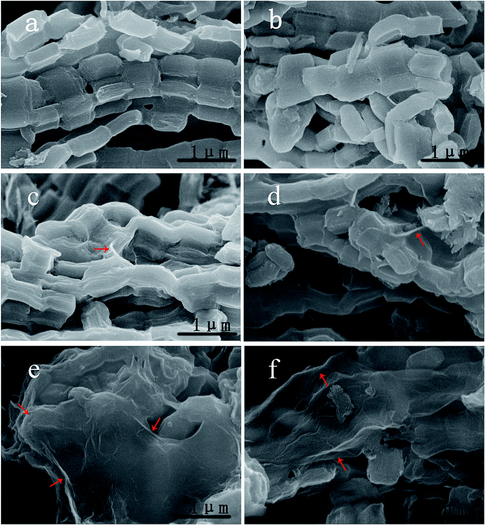 | ||
| Fig. 2 SEM images of the as-prepared materials ((a) CMK-3, (b) CMK-3/S, (c) RGO@CMK-3/S, (d) RGO@CMK-3/S-P, (e) and (f) RGO@CMK-3/S-L). | ||
From the TEM images (Fig. 3a and b), the parallel channels can be obviously observed in CMK-3, and the sulfur nanoparticles were uniformly dispersed in the channels. The tightly coated graphene sheets on the surface of the CMK-3/S particles in the presence of L-lysine are also further confirmed by the TEM images of the RGO@CMK-3/S-L composite (shown in Fig. 3c and d). It can be easily observed that there is a flexible and corrugated thin film (marked by red arrows) wrapped tightly on the surface of the CMK-3/S particles, indicating the feasibility of using L-lysine as a bridging agent to promote the coating of graphene onto the surface of CMK-3/S particles.
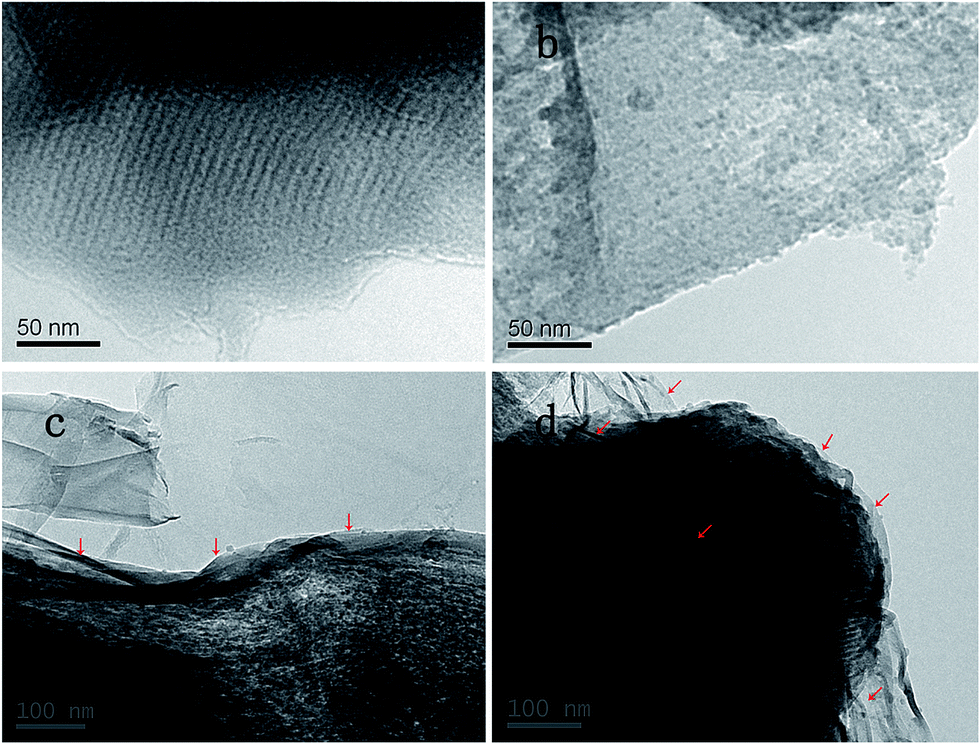 | ||
| Fig. 3 TEM images of CMK-3 (a), the CMK-3 composite (b) and the RGO@CMK-3/S-L composite (c) and (d). | ||
Thermogravimetric analysis (TGA) studies under N2 were used to obtain the accurate content of sulfur in all of the as-prepared samples (shown in Fig. 4a). The weight-losing process at 30–150 °C is attributed to the evaporation of hydroscopic water. The sulfur started to decrease at 150 °C and evaporates completely at about 500 °C, and the sulfur content in the CMK-3/S, RGO@CMK-3/S, RGO@CMK-3/S-P and RGO@CMK-3/S-L sample is 68.4 wt%, 63 wt%, 62 wt% and 62 wt%, respectively. In addition, compared with the pure sulfur powder, the sulfur component in the RGO@CMK-3/S, RGO@CMK-3/S-P and RGO@CMK-3/S-L composites evaporates at a much higher temperature, which suggests that CMK-3 with a graphene skin has a nice encapsulation capability.
 | ||
| Fig. 4 (a) The TG curves of all the samples and pure sulfur tested under a nitrogen flow, (b) electrochemical impedance curves of all the samples, (c) CV profiles of RGO@CMK-3/S-L in the potential window from 1.5 to 3.0 V (versus Li/Li+) at the scan rate of 0.1 mV s−1, (d) galvanostatic charge–discharge profiles of all the samples at 0.5C. | ||
Electrochemical impedance spectroscopy (EIS) measurements were carried out to study the electrochemical kinetics properties of all the samples. As shown in Fig. 4b, all of the impedance spectra consist of a depressed semicircle in the high-medium frequency region followed by a slanted line in the low frequency region. The semicircle can be related to the charge transfer resistance (Rct) at the electrode/electrolyte interface. The linear Warburg part can be attributed to the diffusion of the lithium ions in the bulk of the electrode. It can be easily observed that the RGO@CMK-3/S-L composite has a much smaller semicircle than the other samples, indicating that the transfer resistance (Rct) of the RGO@CMK-3/S-L composite is lower than that of the other three samples. This is on account of the graphene coating providing a more effective electronically conductive network.
Fig. 4c shows the first five cyclic voltammetry (CV) profiles of the RGO@CMK-3/S-L composite electrode in the voltage range of 1.5–3.0 V at a fixed scan rate of 0.1 mV s−1. Two main reduction peaks at around 2.32 V and 2.02 V are observed during the reduction process, indicating a two-step reduction of sulfur. The peak at about 2.32 V involves the reduction of elemental sulfur to soluble lithium polysulfide (Li2Sn, 4 ≤ n ≤ 8), and the peak at about 2.02 V corresponds to the reduction of lithium polysulfides to insoluble Li2S2 and Li2S, respectively.15,26–28 In the oxidation process, only one oxidation peak is observed at about 2.40 V, which corresponds to the oxidation of Li2S2/Li2S to Li2S8.10,13,29 Fig. 4d shows the galvanostatic charge–discharge curves of all of the samples at 0.5C within a potential window of 1.5–2.7 V versus Li+/Li0. It is worth noting that the RGO@CMK-3/S-L sample exhibited the lowest voltage hysteresis (ΔV), compared with RGO@CMK-3/S-P, RGO@CMK-3/S and CMK-3/S, indicating the best transport kinetics of electrons and ions for the RGO@CMK-3/S-L cathode.30,31
An excellent rate performance is one of the most important electrochemical properties for the application of lithium–sulfur batteries. As shown in Fig. 5a, the rate capabilities of all of the samples were performed at discharge rates from 0.1C to 2C (1C = 1675 mA g−1). The discharge capacities gradually decrease with increasing current density for all of the samples, and an improved rate performance for RGO@CMK-3/S-L is clearly seen. The capacity of RGO@CMK-3/S-L is stable at about 970 mA h g−1 after 5 cycles at a rate of 0.1C with an initial discharge capacity of 1296 mA h g−1. As the current density increases, the reversible capacities are 970 (74.8%), 780 (60.2%), 700 (54%) and 660 (50.9%) mA h g−1 at 0.2, 0.5, 1 and 2C, respectively.
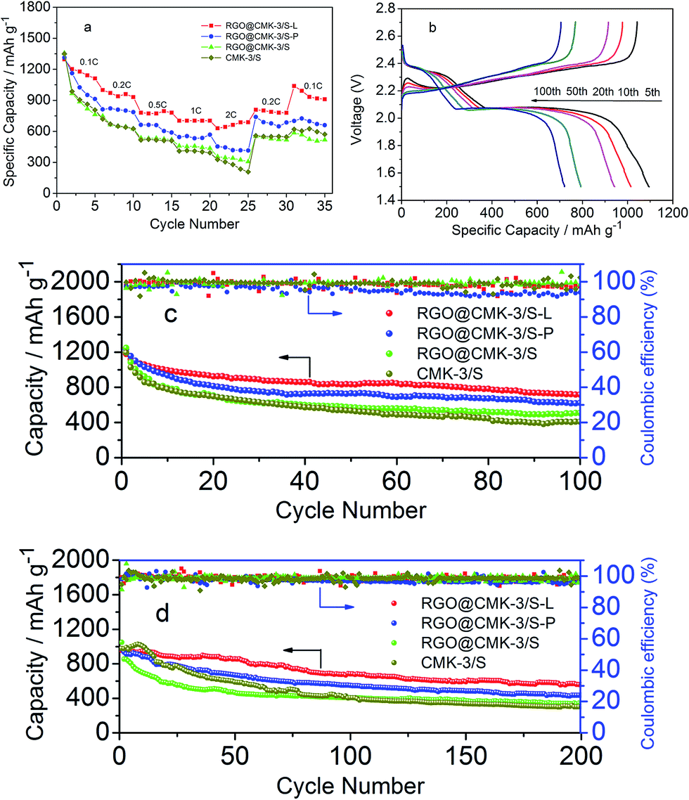 | ||
| Fig. 5 (a) The discharge capacities of all the samples at different discharge rates, (b) the galvanostatic charge–discharge profiles of RGO@CMK-3/S-L at 0.5C, (c) and (d) the cycling performances of all the samples at 0.5C and 1C. | ||
The cycling performances of all of the samples also exhibit different behaviors, as illustrated in Fig. 5c and d. Fig. 5c compares the cycling stability of all of the composites at 0.5C, the RGO@CMK-3/S-L material exhibits the best cycling stability of the samples. The discharge capacity of RGO@CMK-3/S-L started at 1180 mA h g−1, and the capacity of about 720 mA h g−1 was achieved over 100 cycles. In contrast, RGO@CMK-3/S-P, RGO@CMK-3/S and CMK-3/S retained capacities of only 620, 510 and 408 mA h g−1 with capacities of 1237, 1247 and 1194 mA h g−1 for the first cycle, respectively. The improved cycling stability at 0.5C of RGO@CMK-3/S-L was also reflected in the charge–discharge curves (shown in Fig. 5b). RGO@CMK-3/S-L also exhibits the highest capacity retention even at a higher current rate (1C), as shown in Fig. 5d. After an initial discharge capacity of 956 mA h g−1, RGO@CMK-3/S-L achieved a capacity of 570 mA h g−1 at the end of 200 cycles. While the capacities of RGO@CMK-3/S-P, RGO@CMK-3/S and CMK-3/S were only 440, 340 and 300 mA h g−1 respectively after 200 cycles, all of the samples possess almost the same discharge capacity for the first cycle. In addition, it is worth emphasizing that the corresponding coulombic efficiency of all of the samples at 0.5C and 1C was approaching 97%.
The excellent electrochemical performance of RGO@CMK-3/S-L, especially the outstanding cycling stability, closely relates to the unique “double-carbon” structure in which the graphene was uniformly and tightly wrapped on the surface of the CMK-3/S particles with the assistance of L-lysine. This is because the amidogens and carboxyls of L-lysine have strong interactions with the carboxyls and hydroxyls of the CMK-3 and graphene surface, respectively. In this unique “double-carbon” structure, mesoporous carbon with a small pore diameter and a large pore volume can contain the polysulfides to some extent.32 The highly conductive graphene coating skin could not only further improve the electronic conductivity of the CMK-3/S particles but also prevents the dissolution of polysulfides. The stable cycling performance and excellent rate performance imply that the RGO@CMK-3/S-L can meet the demands for EVs and HEVs.
Conclusion
In summary, we controllably prepared a high performance graphene coated CMK-3/S composite, in which sulfur nanoparticles were uniformly dispersed in the channels of the mesoporous carbon and graphene was tightly coated on the CMK-3/S composite surface, via the functionalization of the CMK-3 surface with the assistance of a bridging agent. The amidogens and carboxyls of L-lysine have strong interactions with the carboxyls and hydroxyls of the CMK-3 and graphene surface, respectively, which could promote the tight wrapping of graphene on the surface of the CMK-3/S composite. The graphene coating skin could not only suppress the dissolution of polysulfides, but also greatly enhance the electrical conductivity of the CMK-3/S composite. Electrochemical tests indicate that RGO@CMK-3/S-L exhibits the best electrochemical performance with a rate capacity of about 660 mA h g−1 at a rate of 2C, and a high capacity retention of 59.6% even at 1C after 200 cycles. Therefore, RGO@CMK-3/S-L could be an excellent candidate as a cathode material for high power rechargeable lithium batteries and the method might be applied in large-scale industrial production.Acknowledgements
This work was supported by the Natural Science Foundation of China (NSFC, No. 51272073).Notes and references
- H. B. Yao, G. Y. Zheng, P. C. Hsu, D. S. Kong, J. J. Cha, W. Y. Li, Z. W. Seh, M. T. McDowell, K. Yan, Z. Liang, V. K. Narasimhan and Y. Cui, Improving lithium–sulphur batteries through spatial control of sulphur species deposition on a hybrid electrode surface, Nat. Commun., 2014, 5, 3943–3952 CAS.
- G. M. Zhou, S. F. Pei, L. Li, D. W. Wang, S. G. Wang, K. Huang, L. C. Yin, F. Li and H. M. Cheng, A Graphene–Pure-Sulfur Sandwich Structure for Ultrafast, Long-Life Lithium–Sulfur Batteries, Adv. Mater., 2014, 26, 625–631 CrossRef CAS PubMed.
- X. L. Ji and L. F. Nazar, Advances in Li–S batteries, J. Mater. Chem., 2010, 20, 9821–9826 RSC.
- D. Aurbach, E. Pollak, R. Elazari, G. Salitra, C. S. Kelley and J. Affinito, On the Surface Chemical Aspects of Very High Energy Density, Rechargeable Li–Sulfur Batteries, J. Electrochem. Soc., 2009, 156, A694–A702 CrossRef CAS PubMed.
- S. Moon, Y. H Jung, W. K. Jung, D. S. Jung, J. W. Choi and D. K. Kim, Encapsulated Monoclinic Sulfur for Stable Cycling of Li–S Rechargeable Batteries, Adv. Mater., 2013, 25, 6547–6553 CrossRef CAS PubMed.
- X. Y. Zhou, J. Xie, J. Yang, Y. L. Zou, J. J. Tang, S. C. Wang, L. L. Ma and Q. C. Liao, Improving the performance of lithium–sulfur batteries by grapheme coating, J. Power Sources, 2013, 243, 993–1000 CrossRef CAS PubMed.
- Y. Zhao, W. L. Wu, J. X. Li, Z. C. Xu and L. H. Guan, Encapsulating MWNTs into Hollow Porous Carbon Nanotubes: A Tube-in-Tube Carbon Nanostructure for High-Performance Lithium–Sulfur Batteries, Adv. Mater., 2014, 26, 5113–5118 CrossRef CAS PubMed.
- C. Barchasz, J. C. Lepretre, F. Alloin and S. Patoux, New insights into the limiting parameters of the Li/S rechargeable cell, J. Power Sources, 2012, 199, 322–330 CrossRef CAS PubMed.
- J. Nelson, S. Misra, Y. Yang, A. Jackson, Y. J. Liu, H. L. Wang, H. J. Dai, J. C. Andrews, Y. Cui and M. F. Toney, In operando X-ray Diffraction and Transmission X-ray Microscopy of Lithium Sulfur Batteries, J. Am. Chem. Soc., 2012, 134, 6337–6343 CrossRef CAS PubMed.
- R. Elazari, G. Salitra, A. Garsuch, A. Panchenko and D. Aurbach, Sulfur-impregnated activated carbon fiber cloth as a binder-free cathode for rechargeable Li–S batteries, Adv. Mater., 2011, 23, 5641–5644 CrossRef CAS PubMed.
- G. C. Li, J. J. Hu, G. R. Li, S. H. Ye and X. P. Gao, Sulfur/activated-conductive carbon black composites as cathode materials for lithium/sulfur battery, J. Power Sources, 2013, 240, 598–605 CrossRef CAS PubMed.
- X. L. Ji, K. T. Lee and L. F. Nazar, A highly ordered nanostructured carbon–sulphur cathode for lithium–sulphur batteries, Nat. Mater., 2009, 8, 500–506 CrossRef CAS PubMed.
- J. C. Guo, Y. H. Xu and C. S. Wang, Sulfur-Impregnated Disordered Carbon Nanotubes Cathode for Lithium–Sulfur Batteries, Nano Lett., 2011, 11, 4288–4294 CrossRef CAS PubMed.
- H. L. Wang, Y. Yang, Y. Y. Liang, J. T. Robinson, Y. G. Li, A. Jackson, Y. Cui and H. J. Dai, Graphene-Wrapped Sulfur Particles as a Rechargeable Lithium–Sulfur Battery Cathode Material with High Capacity and Cycling Stability, Nano Lett., 2011, 11, 2644–2647 CrossRef CAS PubMed.
- X. Y. Zhao, J. P. Tu, Y. Lu, J. B. Cai, Y. J. Zhang, X. L. Wang and C. D. Gu, Graphene-coated mesoporous carbon/sulfur cathode with enhancedcycling stability, Electrochim. Acta, 2013, 113, 256–262 CrossRef CAS PubMed.
- W. Z. Bao, Z. A. Zhang, W. Chen, C. K. Zhou, Y. Q. Lai and J. Li, Facile synthesis of graphene oxide@mesoporous carbon hybrid nanocomposites for lithium sulfur battery, Electrochim. Acta, 2014, 127, 342–348 CrossRef CAS PubMed.
- M. P. Yu, R. Li, Y. Tong, Y. R. Li, C. Li, J. D. Hong and G. Q. Shi, A graphene wrapped hair-derived carbon/sulfur composite for lithium–sulfur batteries, J. Mater. Chem. A, 2015, 3, 9609–9615 CAS.
- G. M. Zhou, Y. B. Zhao and A. Manthiram, Dual-Confined Flexible Sulfur Cathodes Encapsulated in Nitrogen-Doped Double-Shelled Hollow Carbon Spheres and Wrapped with Graphene for Li–S Batteries, Adv. Energy Mater., 2015, 5, 1402263 Search PubMed.
- L. F. Xiao, Y. L. Cao, J. Xiao, B. Schwenzer, M. H. Engelhard, L. V. Saraf, Z. Nie, G. J. Exarhos and J. Liu, A Soft Approach to Encapsulate Sulfur: Polyaniline Nanotubes for Lithium–Sulfur Batteries with Long Cycle Life, Adv. Mater., 2012, 24, 1176–1181 CrossRef CAS PubMed.
- F. Wu, J. Z. Chen, R. J. Chen, S. X. Wu, L. Li, S. Chen and T. Zhao, Sulfur/Polythiophene with a Core/Shell Structure: Synthesis and Electrochemical Properties of the Cathode for Rechargeable Lithium Batteries, J. Phys. Chem. C, 2011, 115, 6057–6063 CAS.
- J. Z. Wang, L. Lu, M. Choucair, J. A. Stride, X. Xu and H. K. Liu, Sulfur–graphene composite for rechargeable lithium batteries, J. Power Sources, 2011, 196, 7030–7034 CrossRef CAS PubMed.
- C. X. Zu and A. Manthiram, Hydroxylated Graphene–Sulfur Nanocomposites for High-Rate Lithium–Sulfur Batteries, Adv. Energy Mater., 2013, 3, 1008–1012 CrossRef CAS PubMed.
- C. Su, X. D. Bu, L. H. Xu, J. L. Liu and C. Zhang, A novel LiFePO4/graphene/carbon composite as a performance-improved cathode material for lithium-ion batteries, Electrochim. Acta, 2012, 64, 190–195 CrossRef CAS PubMed.
- S. Jun, S. H. Joo, R. Ryoo, M. Kruk, M. Jaroniec, Z. Liu, T. Ohsuna and O. Terasaki, Synthesis of New, Nanoporous Carbon with Hexagonally Ordered Mesostructure, J. Am. Chem. Soc., 2000, 122, 10712–10713 CrossRef CAS.
- L. L. Zhang, S. Y. Zhao, X. N. Tian and X. S. Zhao, Layered Graphene Oxide Nanostructures with Sandwiched Conducting Polymers as Supercapacitor Electrodes, Langmuir, 2010, 26, 17624–17628 CrossRef CAS PubMed.
- C. F. Zhang, H. B. Wu, C. Z. Yuan, Z. P. Guo and X. W. (David) Lou, Confining Sulfur in Double-Shelled Hollow Carbon Spheres for Lithium–Sulfur Batteries, Angew. Chem., Int. Ed., 2012, 51, 9592–9595 CrossRef CAS PubMed.
- Y. J. Li, H. Zhan, S. Q. Liu, K. L. Huang and Y. H. Zhou, Electrochemical properties of the soluble reduction products in rechargeable Li/S battery, J. Power Sources, 2010, 195, 2945–2949 CrossRef CAS PubMed.
- G. M. Zhou, D. W. Wang, F. Li, P. X. Hou, L. C. Yin, C. Liu, G. Q. (Max) Lu, I. R. Gentle and H. M. Cheng, A flexible nanostructured sulphur–carbon nanotube cathode with high rate performance for Li–S batteries, Energy Environ. Sci., 2012, 5, 8901–8906 CAS.
- X. Y. Tao, F. Chen, Y. Xia, H. Huang, Y. P. Gan, X. R. Chen and W. K. Zhang, Decoration of sulfur with porous metal nanostructures: an alternative strategy for improving the cyclability of sulfur cathode materials for advanced lithium–sulfur batteries, Chem. Commun., 2013, 49, 4513–4515 RSC.
- G. M. Zhou, L. Li, D. W. Wang, X. Y. Shan, S. F. Pei, F. Li and H. M. Cheng, A Flexible Sulfur–Graphene–Polypropylene Separator Integrated Electrode for Advanced Li–S Batteries, Adv. Mater., 2015, 27, 641–647 CrossRef CAS PubMed.
- Z. B. Xiao, Z. Yang, L. Wang, H. G. Nie, M. Zhong, Q. Q. Lai, X. J. Xu, L. J. Zhang and S. M. Huang, A Lightweight TiO2/Graphene Interlayer, Applied as a Highly Effective Polysulfide Absorbent for Fast, Long-Life Lithium–Sulfur Batteries, Adv. Mater., 2015, 27, 2891–2898 CrossRef CAS PubMed.
- X. Liang, Z. Y. Wen, Y. Liu, H. Zhang, L. Z. Huang and J. Jin, Highly dispersed sulfur in ordered mesoporous carbon sphere as a composite cathode for rechargeable polymer Li/S battery, J. Power Sources, 2011, 196, 3655–3658 CrossRef CAS PubMed.
Footnote |
| † Electronic supplementary information (ESI) available. See DOI: 10.1039/c5ra14757c |
| This journal is © The Royal Society of Chemistry 2015 |