Normal-pulse-voltage-assisted in situ fabrication of graphene-wrapped MOF-derived CuO nanoflowers for water oxidation†
Ying
Wang
a,
Shiqi
Wang
a,
Dayan
Liu
a,
Lin
Zhou
a,
Ran
Du
 b,
Ting-Ting
Li
c,
Tingting
Miao
 a,
Jinjie
Qian
 *a,
Yue
Hu
 *a and
Shaoming
Huang
 *ad
*ad
aKey Laboratory of Carbon Materials of Zhejiang Province, College of Chemistry and Materials Engineering, Wenzhou University, Wenzhou, 325000, P. R. China. E-mail: jinjieqian@wzu.edu.cn; yuehu@wzu.edu.cn; smhuang@wzu.edu.cn; Tel: +86-577-88373064
bPhysical Chemistry, Technische Universität Dresden, Bergstr. 66b, Dresden 01062, Germany
cChemistry Institute for Synthesis and Green Application, School of Materials Science and Chemical Engineering, Ningbo University, Ningbo, 315211, P. R. China
dSchool of Materials and Energy, Guangdong University of Technology, Guangzhou, 510006, P. R. China
First published on 6th June 2020
Abstract
Chemical vapor deposition (CVD) and normal pulse voltage (NPV) are adopted to construct high-quality graphene-wrapped CuO nanoflowers grown in situ on copper foam (CuO NP@G/CF) as an efficient oxygen evolution reaction (OER) electrocatalyst. The CuO NF@G/CF electrode exhibits a small overpotential of 320 mV to drive a current density of 10 mA cm−2 with a low Tafel slope of 63.1 mV dec−1. This enhancement in OER performance stems from the synergistic effect between highly conductive graphene and hierarchically porous CuO nanoflowers with a number of high-density active sites and open spaces.
Hydrogen is the key factor in the conversion of renewable energies such as solar energy and wind energy into an ideal energy source.1 Water splitting is an effective way to produce hydrogen. Meanwhile, we learn that the hydrogen evolution reaction (HER) and oxygen evolution reaction (OER) are two important half-reactions in overall water splitting.2 Between them, the OER is a four-electron transfer reaction with slow kinetics and a large overpotential that severely hinders the rapid production of hydrogen.3 In this context, it is necessary to prepare (electro)catalysts to improve the efficiency of the OER. So far, the most effective OER catalysts are still IrO2 and RuO2, but these noble metal catalysts cannot be used widely due to their high cost, low abundance, and low durability.4 Recently, Cu-based materials have attracted increasing interest as water splitting electrocatalysts owing to their low cost, rich reserves and non-toxicity,5–7 but the overpotential and Tafel slope of Cu-based complexes are both high and far from satisfactory for OER.8,9 Therefore, the development of high-efficiency Cu-based electrocatalysts with a high density of active sites remains a great challenge.
Generally speaking, the surface area and active sites of catalysts are closely related to their morphology and grain size.10 Therefore, the rational design of the micro/nano-structure of the catalysts is the basic strategy for enhancing performance. More recently, metal–organic frameworks (MOFs) have appeared as an important type of self-sacrificing precursor for the realization of nanostructured TM oxides due to their high porosity and adjustable ordered structure.11,12
However, direct applications of nanostructured CuO are still restricted by their intrinsic low conductivity. To increase the conductivity of these materials, some conductive agents such as carbon nanotubes (CNTs), polyaniline (PANI) and graphene oxide (GO) are typically mixed with transition metal oxides, and then fixed to the electrode surface using polymeric binders.13–15 But these polymer binders will increase a series of resistances and reduce the catalytic performance.16,17 In contrast, the in situ direct growth of CuO active materials on the current collectors can solve these problems. In this context, if graphene was introduced into the system simultaneously, the conductivity of CuO could be increased to improve the activity of the materials as well as their mechanical stability.
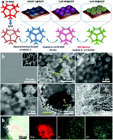
Based on the above considerations, we herein report a novel method for the fabrication of graphene-wrapped CuO nanoflowers on copper foam (CuO NF@G/CF) for efficient electrocatalytic water oxidation. As shown in Fig. 1a (for details, see the Experimental section), the high-quality graphene is grown on CF (G/CF) by the typical chemical vapor deposition (CVD) method.18,19 Subsequently, a typical Cu-based MOF precursor (HKUST-1) can be successfully synthesized by the facile electrochemical method on the as-prepared G/CF (HKUST-1@G/CF).20 After soaking in an alkaline solution, graphene-wrapped CuO nanoparticles (CuO NP@G/CF) are obtained. Finally, these as-obtained CuO nanoparticles (CuO NPs) are further turned into CuO nanoflowers (CuO NFs) by the normal pulse voltage (NPV) method to form CuO NF@G/CF.
From scanning electron microscopy (SEM) images of G/CF and CF (Fig. 1b and Fig. S1, ESI†), it can be seen that the rough CF surface becomes smooth and flat. Moreover, it is observed that the 3-dimensional (3D) porous CF skeleton is fully covered by uniformly continuous graphene without cracks or fractures (G/CF). And we find that a single graphene layer is confirmed by the transmission electron microscopy (TEM) image (Fig. S2a, ESI†). In addition, the selected area electron diffraction (SAED) pattern further confirms the presence of graphene, exhibiting sharp and nonoverlapping diffraction spots (Fig. S2b, ESI†). The Raman spectrum of G/CF shows two characteristic peaks from the as-obtained graphene at 1584 cm−1 and 2685 cm−1, which can be rationally attributed to the G and 2D peaks, respectively (Fig. S3, ESI†). In this case, a very weak D peak at 1345 cm−1 indicates fewer defects and good quality, which tends to mean excellent performance. Fig. 1c shows an SEM image of HKUST-1@G/CF, which shows that most of these octahedral HKUST-1 can be successfully obtained. By treating them in alkaline solution, the metastable coordination bonds between BTC ligands and Cu(II) ions spontaneously dissociate with the competitive components of hydroxide ions to form CuO NPs (Fig. 1d). Compared to the HKUST-1 precursors, the size of the CuO NPs is obviously reduced to 300–500 nm with an irregular morphology, which may result in an increase in OER activity. The SEM image of CuO NF@G/CF (Fig. 1e) demonstrates that the conversion of CuO NPs to CuO NFs is well achieved, in which a single graphene-free CuO NF is assembled from a number of CuO nanosheets, which are interconnected with each other and lead to plenty of voids (inset of Fig. 1e). TEM images of CuO NF@G/CF (Fig. 1f and g) further shows that each ultra-thin CuO nanosheet has an average width of ∼15 nm, which is beneficial to the exposure of active sites and thus leads to enhanced catalytic performance. Meanwhile, the well-resolved lattice fringes with an interplanar spacing of 0.252 nm are assigned to the (−111) crystal plane of CuO (inset of Fig. 1g). Furthermore, the EDX element mapping (Fig. 1h) indicates the uniform presence of Cu, C and O elements. Among these, the distribution of C element confirms that the as-treated CuO NFs are well wrapped with graphene, consistent with the above observations.
The Raman spectrum of HKUST-1@G/CF can be well matched with those of HKUST-1/CF and G/CF, respectively (Fig. S4a, ESI†), further proving that the in situ growth of Cu-MOF precursor on G/CF can successfully form the covering structure of HKUST-1@G/CF with strong G and 2D peaks of 1583 cm−1 and 2687 cm−1, respectively. Fig. S4b (ESI†) shows the XRD patterns of HKUST-1/CF, CuO NP@G/CF and CuO NF@G/CF. After immersion in 2.0 M KOH solution, only the peaks of CuO (35.6° and 38.8°) and the substrate CF (43.3° and 50.4°) are observed, indicating that HKUST-1 is completely converted into CuO NPs. Moreover, after the CuO NP@G/CF has been treated by the NPV method, the crystal phase does not change, with two crystal planes of (−111) and (111) for CuO, but the CuO NPs with a smaller surface area turn into hierarchically porous CuO NFs with more active sites.
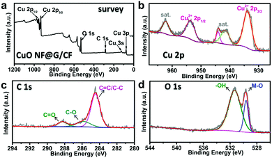
The components and the valence states of CuO NF@G/CF are further examined by X-ray photoelectron spectroscopy (XPS). The full survey spectrum indicates the presence of Cu, C and O elements (Fig. 2a). As shown in Fig. 2b, the valence state of Cu is further demonstrated by the high-resolution Cu 2p spectrum where the peak with a binding energy of 933.9 eV is attributed to Cu 2p3/2 with two satellite peaks at 941.0 and 943.7 eV, while the peak with a binding energy of 953.9 eV is indexed to Cu 2p1/2, accompanied by a satellite peak at 962.5, which is characteristic of typical CuO materials.21,22 Moreover, the Cu LMM spectrum further demonstrates the successful preparation of CuO (Fig. S5, ESI†). The C 1s spectrum of CuO NF@G/CF in Fig. 2c shows multiple peaks at 284.5, 285.9 and 288.2 eV, corresponding to the graphite of C–C/C![[double bond, length as m-dash]](https://www.rsc.org/images/entities/char_e001.gif) C bonds, C–O bonds, and C
C bonds, C–O bonds, and C![[double bond, length as m-dash]](https://www.rsc.org/images/entities/char_e001.gif) O groups in CuO NF@G/CF, respectively.23 As for the O 1s spectrum (Fig. 2d), the peak at 529.6 eV is attributed to the oxygen atoms from the Cu–O bonds, and the peak located at 531.3 eV can be ascribed to the oxygen atoms of –OH− groups from the CuO surface.22,24
O groups in CuO NF@G/CF, respectively.23 As for the O 1s spectrum (Fig. 2d), the peak at 529.6 eV is attributed to the oxygen atoms from the Cu–O bonds, and the peak located at 531.3 eV can be ascribed to the oxygen atoms of –OH− groups from the CuO surface.22,24
 | ||
| Fig. 2 (a) The full XPS survey spectrum of CuO NF@G/CF; (b–d) the deconvoluted XPS spectra of Cu 2p, C 1s and O 1s. | ||
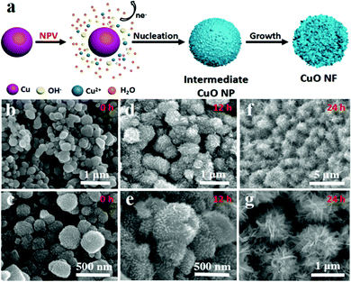
For comparison with our target materials, we have also prepared pure CuO NPs and CuO NFs using a similar synthetic route, and explored the mechanism of the NPV method for the formation of a flower-like morphology at the same time. The HKUST-1 precursors were fabricated in situ on CF by the electrochemical method (HKUST-1/CF) with an octahedron morphology (Fig. S6, ESI†), which is the same as that of HKUST-1@G/CF above. The CuO NP/CF is obtained by immersing the HKUST-1/CF precursor into 2.0 M KOH solution, which clearly shows that the morphology of the CuO NPs is irregular with a size of 300–500 nm (Fig. S7, ESI†). The CuO NPs are conveniently converted into CuO NFs using our NPV method, whose formation mechanism can be briefly summarized as follows: Cu → Cu2+ (1); Cu2+ + 4OH− →[Cu(OH)4]2− (2); Cu[(OH)4]2− → CuO + H2O (3). As shown in Fig. 3a, Cu atoms from CF tend to be oxidized into Cu2+ ions under the action of a high voltage (eqn (1)). In the strong alkaline solution, Cu2+ ions coordinate to OH− anions to form a [Cu(OH)4]2− complex (eqn (2)). We learn that [Cu(OH)4]2− ions are unstable in thermodynamics and easily dehydrated to form CuO (eqn (3)).
As the pulse voltage increases, CF becomes oxidized more quickly and the concentration of Cu2+ cations in the solution increases instantaneously, resulting in a large amount of CuO nuclei on the surface of the CuO NPs. In this context, the initial surface of CuO NP/CF is smooth and almost free of particles before the NPV step (Fig. S7, ESI†). However, after NPV without soaking, the surface of the CuO NPs is observed to be rough and many particles are present (Fig. 3b and c). Furthermore, when the as-electrolyzed CuO NP/CF is kept in the NPV solution for 12 hours, the CuO nuclei on the surface of the CuO NPs grow further into CuO nanosheets (Fig. 3d and e). If kept in the KOH solution for 24 hours, these small nanosheets grow further into larger nanosheets and eventually form CuO NFs (Fig. 3f and g). The TEM and high-resolution TEM images of CuO NFs show a hierarchical flower-like structure with an interplanar spacing of 0.235 nm attributed to the (111) crystal plane of CuO (Fig. S8, ESI†). The uniform distribution of Cu and O is confirmed from the EDS elemental mapping images (Fig. S9, ESI†). To further explore the role of NPV in the formation of CuO NFs, CuO NP/CF is directly soaked in 1.0 M KOH solution after NPV as a comparison. After 7 days, a few particles appear on the surface of the CuO NPs (Fig. S10, ESI†) indicating that NPV plays two main roles: (1) Cu2+ cations are electrolyzed from CF to form CuO NFs; (2) NPV promotes the rapid nucleation of CuO during the electrolysis. At the same time, HKUST-1/CF can also become CuO nanosheets on the surface by the NPV method, further verifying its general application in the growth of CuO nanosheets (Fig. S11, ESI†).
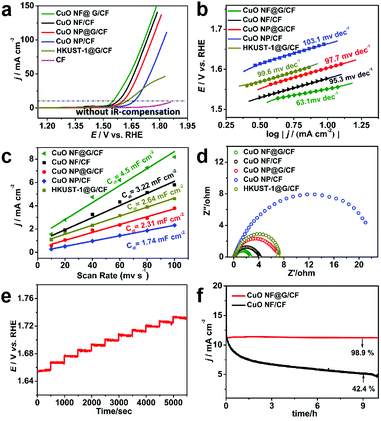
Electrocatalytic OER performance is evaluated by measurement in a typical standard three-electrode system. The synthesized samples are directly tested as the working electrode in a 1.0 M KOH aqueous solution with a scan rate of 2 mV s−1. Fig. 4a exhibits the linear sweep voltammetry (LSV) curves, where pristine CF shows poor catalytic activity with no obvious current increase at 1.65 V vs. RHE, while CuO NF@G/CF exhibits outstanding OER activity requiring a low overpotential of 320 mV to achieve a current density of 10 mA cm−2. CuO NF/CF, CuO NP/CF and HKUST-1@G/CF show moderate water oxidation activity, which requires overpotentials of 347 mV, 430 mV and 398 mV, respectively. Compared to CuO NP/CF, the higher catalytic activity of CuO NF/CF is derived from a large number of NPV-induced CuO nanosheets with a rich active surface, which are conducive to fast mass transport and abundant catalytic sites. On the other hand, the reduced overpotentials can be clearly observed between CuO NP/CF and CuO NP@G/CF, CuO NF/CF and CuO NF@G/CF due to the different conductivities among them. In other words, the introduction of high-quality graphene prepared by the CVD method improves OER activity for both CuO NF/CF and CuO NP/CF. Fig. 4b shows the Tafel slope of these electrodes, in which CuO NF@G/CF has the smallest Tafel slope of 63.1 mV dec−1 (CuO NP/CF, 103.1 mV dec−1; CuO NP@G/CF, 97.7 mV dec−1; CuO NF/CF, 95.3 mV dec−1, HKUST-1@G/CF, 99.6 mV dec−1) indicating the most favorable kinetics. Meanwhile, the electrochemical surface areas (ECSAs) in a non-faradaic potential window of 1.22–1.32 V vs. RHE are easily obtained from CVs at different scan rates (Fig. S12, ESI†), and the slopes of the linear relationship give the double-layer capacitance (Cdl, Fig. 4c). The Cdl and ECSA of CuO NF@G/CF are 4.5 mF cm−2 and 112.6 cm2, respectively, which are larger than those of the other active materials, as shown in Tables S1 and S2 (ESI†), thus providing more active sites for OER. In Fig. 4d, CuO NF@G/CF exhibits the smallest semicircle in comparison with the other three counterparts, which means the smallest charge transfer interface resistance and the fastest kinetics consistent with these Tafel slope values of these electrodes. Fig. 4e shows the multi-step chronopotential curve of CuO NF@G/CF in 1.0 M KOH, whose current intensity is increased from 40 to 60 mA cm−2 and the current density is increased for each additional 4 mA cm−2 held for an interval of 500 s. The starting step remains at 1.325 V vs. RHE for 500 s and other flat staircases have similar results, indicating the excellent mechanical strength, conductivity and material transport of the CuO NF@G/CF electrode. Most importantly, the long-term durability test shows an initial current density of 11 mA cm−2 and a negligible 1.1% performance loss after 10 hours, implying the graphene does provide strong protection and impede the decomposition of the flower-like CuO material during the severe electrolyzing conditions (Fig. 4f). In addition, the morphology and structure of CuO NF@G/CF after the stability test are basically unchanged, which also shows its good stability (Fig. S13, ESI†). The faradaic efficiency of the catalysts was measured by a fluorescence-based oxygen sensor, and the results are shown in Fig. S14 (ESI†). By comparing the theoretical and experimental amounts of oxygen evolution after 3 h of electrolysis, the Faraday efficiency can reach more than 97%.
In summary, we have proposed a normal-pulse-voltage-assisted method for the in situ preparation of high-quality graphene-wrapped CuO nanoflowers on CF. The as-obtained CuO NF@G/CF electrode exhibits a competitive OER catalytic performance in 1.0 M KOH solution, which is attributed to the remarkable improvement in conductivity from the high-quality graphene and the large number of active sites in the unique architecture of flower-like CuO. Moreover, this catalyst can maintain long-term catalytic activity with a negligible drop in current density, indicating ultrastable electrochemical stability for graphene protection on the interface. More importantly, the rational design of a graphene-coating on a 3D morphology will provide a new idea for enhancing the OER activity of a catalyst.
Conflicts of interest
There are no conflicts to declare.Notes and references
- P. Du and R. Eisenberg, Energy Environ. Sci., 2012, 5, 6012–6021 RSC.
- J. Wang, W. Cui, Q. Liu, Z. Xing, A. M. Asiri and X. Sun, Adv. Mater., 2016, 28, 215–230 CrossRef CAS PubMed.
- Q. Liu, L. Xie, Z. Liu, G. Du, A. M. Asiri and X. Sun, Chem. Commun., 2017, 53, 12446–12449 RSC.
- Y. Lee, J. Suntivich, K. J. May, E. E. Perry and Y. Shao-Horn, J. Phys. Chem. Lett., 2012, 3, 399–404 CrossRef CAS PubMed.
- M. Qian, X. Liu, S. Cui, H. Jia and P. Du, Electrochim. Acta, 2018, 263, 318–327 CrossRef CAS.
- X. Liu, S. Cui, Z. Sun, Y. Ren, X. Zhang and P. Du, J. Phys. Chem. C, 2016, 120, 831–840 CrossRef CAS.
- X. Du, J. Huang, Y. Feng and Y. Ding, Chin. J. Catal., 2016, 37, 123–134 CrossRef CAS.
- K. S. Joya and H. J. M. de Groot, ACS Catal., 2016, 6, 1768–1771 CrossRef CAS.
- J. X. Wu, C. T. He, G. R. Li and J. P. Zhang, J. Mater. Chem. A, 2018, 6, 19176–19181 RSC.
- T. Tian, M. Zheng, J. Lin, X. Meng and Y. Ding, Chem. Commun., 2019, 55, 1044–1047 RSC.
- T. Y. Ma, S. Dai, M. Jaroniec and S. Z. Qiao, J. Am. Chem. Soc., 2014, 136, 13925–13931 CrossRef CAS PubMed.
- P. He, X. Y. Yu and X. W. Lou, Angew. Chem., Int. Ed., 2017, 56, 3897–3900 CrossRef CAS PubMed.
- J. W. Su, G. L. Xia, R. Li, Y. Yang, J. T. Chen, R. H. Shi, P. Jiang and Q. W. Chen, J. Mater. Chem. A, 2016, 4, 9204–9212 RSC.
- D. G. Lee, S. H. Kim, S. H. Joo, H. I. Ji, H. Tavassol, Y. Jeon, S. Choi, M. H. Lee, C. Kim, S. K. Kwak, G. Kim and H. K. Song, Energy Environ. Sci., 2017, 10, 523–527 RSC.
- X. Li, Y. Fang, X. Lin, M. Tian, X. An, Y. Fu, R. Li, J. Jin and J. Ma, J. Mater. Chem. A, 2015, 3, 17392–17402 RSC.
- S. S. Cui, X. Liu, Z. J. Sun and P. W. Du, ACS Sustainable Chem. Eng., 2016, 4, 2593–2600 CrossRef CAS.
- T.-T. Li, J. Qian and Y.-Q. Zheng, RSC Adv., 2016, 6, 77358–77365 RSC.
- W. Liu, S. Kraemer, D. Sarkar, H. Li, P. M. Ajayan and K. Banerjee, Chem. Mater., 2013, 26, 907–915 CrossRef.
- G. Eres, M. Regmi, C. M. Rouleau, J. H. Chen, I. N. Ivanov, A. A. Puretzky and D. B. Geohegare, ACS Nano, 2014, 8, 5657–5669 CrossRef CAS PubMed.
- L. L. Jiang, X. Zeng, M. Li, M.-Q. Wang, T.-Y. Su, X.-C. Tian and J. Tang, RSC Adv., 2017, 7, 9316–9320 RSC.
- X. Liu, S. Cui, Z. Sun and P. Du, Electrochim. Acta, 2015, 160, 202–208 CrossRef CAS.
- X. Liu, H. Zheng, Z. Sun, A. Han and P. Du, ACS Catal., 2015, 5, 1530–1538 CrossRef CAS.
- Y. Ni, L. H. Yao, Y. Wang, B. Liu, M. H. Cao and C. W. Hu, Nanoscale, 2017, 9, 11596–11604 RSC.
- M. Devaraj, R. K. Deivasigamani and S. Jeyadevan, Colloids Surf., B, 2013, 102, 554–561 CrossRef CAS PubMed.
Footnote |
| † Electronic supplementary information (ESI) available. See DOI: 10.1039/d0cc03132a |
| This journal is © The Royal Society of Chemistry 2020 |


