 Open Access Article
Vacuum-evaporable spin-crossover complexes: physicochemical properties in the crystalline bulk and in thin films deposited from the gas phase†‡
H.
Naggert
a,
J.
Rudnik
a,
L.
Kipgen
b,
M.
Bernien
b,
F.
Nickel
b,
L. M.
Arruda
b,
W.
Kuch
b,
C.
Näther
a and
F.
Tuczek
*a
aInstitute of Inorganic Chemistry, Christian-Albrechts-University Kiel, Max-Eyth-Str. 2, 24118 Kiel, Germany. E-mail: ftuczek@ac.uni-kiel.de
bInstitute for Experimental Physics, Freie Universität Berlin, Arnimallee 14, 14195 Berlin, Germany
First published on 8th May 2015
Abstract
Four analogues of the spin-crossover complex [Fe(H2Bpz2)2(phen)] (H2Bpz2 = dihydrobis(pyrazolyl)borate; 2) containing functionalized 1,10-phenanthroline (phen) ligands have been prepared; i.e., [Fe(H2Bpz2)2(L)], L = 4-methyl-1,10-phenanthroline (3), 5-chloro-1,10-phenanthroline (4), 4,7-dichloro-1,10-phenanthroline (5), and 4,7-dimethyl-1,10-phenanthroline (6). The systems are investigated by magnetic susceptibility measurements and a range of spectroscopies in the solid state and in thin films obtained by physical vapour deposition (PVD). Thermal as well as light-induced SCO behaviour is observed for 3–6 in the films. By contrast, thermal SCO in the solid state occurs only for 3 and 4 but is absent for 5 and 6. These findings are discussed in the light of cooperative and intermolecular interactions.
Introduction
The development of molecular switches opens up new applications in spintronics and data storage.1,2 An important aspect of this research area refers to spin-state switching, which is based on electronic bistability in spin-crossover (SCO) compounds.3 As shown by us and others, the SCO complexes [Fe(H2Bpz2)2(L)] (H2Bpz2 = dihydrobis(pyrazolyl)borate, L = 2,2′-bipyridine (bipy, 1) or 1,10-phenanthroline (phen, 2))4–6 can be used for the preparation of high-quality thin films by deposition from the gas phase.1,7–10 In these compounds the iron(II) center is surrounded by bidentate ligands with the positive charge being compensated by two H2Bpz2-ligands (Fig. 1). Upon cooling from room temperature to 160 K, spin crossover from 5T2g to 1A1g occurs, and below 50 K light-induced spin state switching (LIESST) into a metastable 5T2g state is possible.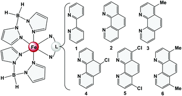 | ||
| Fig. 1 The complexes [Fe(H2Bpz2)2(L)] investigated in this work, based on functionalized 1,10-phenanthroline ligands (3–6). | ||
Recently, we performed valence-band photoemission studies on ultrathin films (∼6 monolayers) on Au(111) of [Fe(H2Bpz2)2(phen)] (2) deposited from the gas phase.11 Vacuum-UV light induced excited spin state trapping (VUVIESST) was observed at temperatures below 50 K. By additionally irradiating the sample with green light the steady-state spin-transition temperature at which γHS = γLS = 0.5 could be shifted from 37 K to 99 K. Moreover, mono- and submonolayers of 2 were prepared by thermal evaporation and investigated by high-resolution STM-topography at 5 K. Electron-induced excited spin state trapping (ELIESST) was observed for single molecules of 2 in a double layer on Au(111). STS indicated a change in the HOMO–LUMO-gap from ∼2 eV in the low-spin state to a much smaller value in the high-spin state, in agreement with DFT calculations.1,11 The composition of the first layer of 2 on Au(111) was further investigated by thermal and angle-dependent near-edge X-ray absorption fine structure (NEXAFS). Importantly, an isotropic Fe L2,3 XA spectrum was obtained that reflected a high-spin state over the full temperature range, and angle dependent nitrogen K-edge XAS indicated an orientation of 1,10-phenanthroline of about 16° with respect to the surface. This information and further high-resolution STM data showed that in a submonolayer on Au(111) the complex decomposes into the bidendate ligand 1,10-phenanthroline and high-spin Fe(H2Bpz2)2.9 This suggests that the first double layer of [Fe(H2Bpz2)2(phen)] (2) on Au(111) identified by STM (see above) consists of 1,10-phenanthroline molecules resulting from decomposition of 2 on this surface.
One possible strategy to prevent decomposition of [Fe(H2Bpz2)2(phen)] (2) on Au(111) is to reduce the interaction of this complex with the surface. This may be achieved by attaching substituents to the phen and bipy ligands. In the literature [Fe(H2Bpz2)2(L)] complexes with annulated bipyridyl co-ligands or bipy/phen ligands functionalized by diarylethene or π-radical ligands have been reported;12,13 however, the properties of these systems with respect to thermal deposition have not been described. Herein, we investigate the influence of a chemical modification of the 1,10-phenanthroline ligands on the physicochemical properties of [Fe(H2Bpz2)2(phen)] (2). In particular, we want to study how methyl and chlorine substituents on the 1,10-phenanthroline ligand of 2 affect its SCO properties in the bulk and in thin films (Fig. 1). To this end we have prepared four analogues of 2 containing functionalized 1,10-phenanthroline ligands; i.e., [Fe(H2Bpz2)2(L)], L = 4-methyl-1,10-phenanthroline (3), 5-chloro-1,10-phenanthroline (4), 4,7-dichloro-1,10-phenanthroline (5), and 4,7-dimethyl-1,10-phenanthroline (6). Information on the spin crossover behaviour of 3–6 is derived from temperature-dependent susceptibility measurements, Mössbauer spectroscopy and single crystal structure determination. Moreover, vacuum deposited films of 3–6 have been fabricated by thermal evaporation, and the thermal SCO, LIESST and reverse-LIESST characteristics14 are studied by temperature-dependent optical transmission spectroscopy. Finally, infrared and resonance Raman spectroscopy as well as synchrotron-based XA-spectroscopy are performed on microcrystalline powders and vacuum-deposited films. The results are discussed in the light of cooperative and intermolecular interactions which are present in the crystalline bulk material but absent in vacuum-deposited films.
Results and discussion
X-ray crystallography
Following the method reported for the synthesis of 1 and 2 microcrystalline powders were obtained for compounds 3–6 with methanol as the solvent.4,15 Attempts to crystallize these complexes from other solvents did not yield suitable single crystals either; only for 6 single crystals could be obtained using a toluene–n-hexane mixture. Compound 6·0.5 C7H8 crystallizes in the space group P-1 with Z = 2 molecules in the unit cell. The asymmetric unit consists of one complex in the general position and one half of a toluene molecule, which is located on the center of inversion and shows a random orientation. At room-temperature the disorder could not be refined; therefore, additional datasets were measured at 200 K and 110 K (ESI,‡ Table S1).In the crystal structure of 6·0.5 C7H8 the Fe(II) cations are coordinated by two H2Bpz2 anions and one 4,7-dimethyl-1,10-phenanthroline ligand within a slightly distorted octahedral geometry. The FeN-bond distances are between 2.222–2.170 Å at 293 K and thus are in a range expected for Fe(II) in a high-spin configuration. Upon cooling only small changes in the Fe–N distances are observed (2.2210–2.1790 Å at 200 K and 2.220–2.1693 Å at 110 K), indicating that no SCO occurs in this temperature range. The discrete complexes are arranged into dimers by intermolecular face-to-face π–π-interactions between 4,7-dimethyl-1,10-phenanthroline ligands of neighbouring complexes (Fig. 2a, b). The interplanar distance between these ligands amounts to 3.507 Å. Similar dimers have also been observed by Real et al. in the crystal structure of 2, which exhibits SCO with a T1/2 of 164 K. However, in 2 this distance is ∼10% longer (3.936 Å; Fig. 2c).4 Interestingly, Halcrow et al. reported an interplanar distance of 3.485 Å and 3.459 Å between the phenazine ligands of [Fe(H2Bpz2)2(dipyrido[3,2-a:2′,3′(6,7,8,9-tetrahydro)phenazine)]], which remains in the high-spin state between 300 K and 70 K, suggesting that a short dimer–dimer distance might be correlated with a lack of SCO behavior.12 The short phen–phen distance in 6·0.5 C7H8 appears to be the result of perfect stacking (Fig. 2b). In particular the methyl groups of one phen ligand are exactly positioned above the center of one C6 ring in a neighbouring phen ligand such that the two phen ligands (and the attached complex units) get closely interlocked. In 6·0.5 C7H8 the angle ϕ(N1–Fe–N4) of 97.76 is significantly enlarged with respect to 2 (ϕ(N1–Fe–N4) = 92.47), leading to a distortion of the FeN6 core. This may also be a result of strong intermolecular face-to-face π–π-interactions, leading to steric repulsion between a 4,7-dimethyl-1,10-phenanthroline ligand and a neighboring complex (cf. Fig. 2a, red). A similar repulsion appears to be absent in 2 (Fig. 2c red) where the interplanar phen–phen distance is longer.
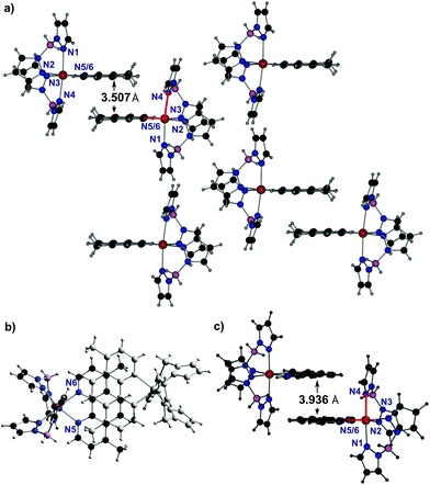 | ||
| Fig. 2 1D stacking motifs in 6·0.5 C7H8 at 293 K in the side view (a) and in the top view (b). For comparison compound 2 (c) taken from Real et al.4 Color code: C (black), H (grey), B (pink), N (blue), Fe (orange) and toluene (not shown). | ||
While no single crystal data could be obtained for 3–6, all of these compounds were characterized by X-ray powder diffractometry (cf. ESI,‡ S2). Not surprisingly, the XRPD pattern of 6·0.5 C7H8 does not correspond to that of 6. However, the XRPD pattern of compound 6 is very similar to that of 5, indicating that both compounds are isotypic. This can be explained by the fact that in compound 6 the two chloro substituents in 5 are exchanged by methyl groups which exhibit similar van der Waals radii (the so-called chloro-methyl exchange rule).16
Thermal spin-crossover in the solid state
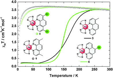
In order to analyse the spin state of iron(II) centres in compounds 3–6 magnetic susceptibility measurements were performed. Plots of the product χMT vs. the temperature (T) are given in Fig. 3; the thermal transition temperatures T1/2 are summarized in Table 1. Compound 4 shows a fairly steep spin transition from 0.19 cm3 K mol−1 at 10 K to 3.54 cm3 K mol−1 at 300 K with a T1/2 of 151 K. For 3, a less abrupt spin transition from 0.21 cm3 K mol−1 at 10 K to 3.54 cm3 K mol−1 at 300 K with a transition temperature of T1/2 = 165 K is found. Both 3 and 4 have about 5% high-spin contribution at low temperatures. Compounds 5 and 6, in contrast, are predominantly high spin; i.e., the susceptibility sharply increases in the range below 20 K and remains at values around 3.5 cm3 K mol−1 for 5 and 6 upon further increasing the temperature to 300 K. The high-temperature χMT values of 3–6 are considerably larger than expected for pure S = 2 systems (χMT = 3.02 cm3 K mol−1), which is caused by spin orbit coupling.| # | T 1/2 [K] | 300 K | 80 K | ||
|---|---|---|---|---|---|
| Δ [mm s−1] | ΔEQ [mm s−1] | δ [mm s−1] | ΔEQ [mm s−1] | ||
| 3 | 165 | 1.00 | 1.53 | 0.53 | 0.48 (4% HS) |
| 4 | 151 | 1.00 | 1.55 | 0.53 | 0.40 (5% HS) |
| 5 | HS | 1.00 | 1.80 | 1.15 | 2.40 (99% HS) |
| 6 | HS | 0.96 | 1.72 | 1.09 | 2.35 (100% HS) |
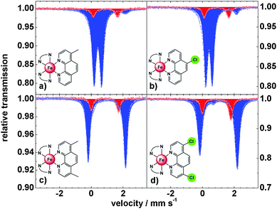
To obtain further information on the spin-state of the iron centers, Mössbauer spectra were recorded at 300 K and 80 K (Fig. 4 and Table 1). At 300 K the spectra of 3 and 4 with monosubstituted 1,10-phenanthroline ligands show a doublet with δ = 1.00 mm s−1, indicative of high-spin iron(II) centers. At 80 K the isomer shift decreases to δ = 0.53 mm s−1, typical for low spin iron centers. In both compounds an amount of ∼5% high spin species is observed at 80 K, in agreement with the magnetic data. Compounds 5 and 6 with difunctionalized ligands exhibit isomer shifts of δ = 1.00 and 0.96 mm s−1, resp., at 300 K and δ = 1.15 and 1.09 mm s−1, resp., at 80 K, indicative of HS configurations at both temperatures.
The thermal spin crossover in the solid state thus can be summarized as follows: compounds 3 and 4 are typical spin crossover compounds like compound 2 (T1/2 = 163 K).4,7 In 4, the electron withdrawing effect of the chlorine group lowers the transition temperature to T1/2 = 151 K while the transition temperature is increased to T1/2 = 165 K in 3 due to the electron-donating effect of the methyl group. In the case of the difunctionalized compounds 5 and 6 the 5T2 state is stabilized down to 20 K; i.e., the spin transition of the parent complex 2 becomes largely suppressed in the crystalline bulk material.
Spin-crossover in vacuum-deposited films
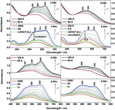
All compounds can be evaporated in a vacuum to obtain films on quartz substrates. Infrared spectra of the films are found to be very similar to those recorded for the bulk material (ESI,‡ S3 and S4); an example is given in Fig. 5 for compound 6. The symmetric and antisymmetric B–H vibrations, e.g., are detectable in the bulk as well as in the film at νasym(B–H) = 2416 cm−1 and νsym(B–H) = 2277 cm−1, which clearly indicates a successful thermal deposition without decomposition. Similar observations apply to compounds 3–5. To monitor the spin crossover in the films temperature dependent UV/vis absorption spectra were measured. For comparison microcrystalline powders of 3–6 dispersed in KBr-pellets were investigated (Fig. 6).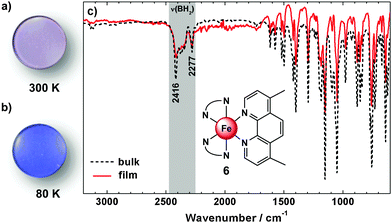 | ||
| Fig. 5 Physical vapour deposited film on a quartz disc of 6 at 300 K (a) and 80 K (b). FT-IR spectra (c) of the bulk material (black dotted) and the vacuum deposited material (red) of 6 at 300 K. | ||
The metal-to-ligand charge-transfer (MLCT) bands of 2 at 500–650 nm are more intense in the LS than in the HS state.3,7 For 3, the MLCT band centred at 550 nm at 300 K similarly evolves into a more intense three-band pattern with maxima at 526, 567 and 624 nm at 80 K, both in KBr and in the film. Similar observations are made for 4. Importantly, the films of 3 and 4 exhibit the LIESST effect; i.e., at 5 K the low-spin state can be converted back to the high-spin state by irradiation at 519 nm for 5 minutes. For 6, the MLCT band exhibits two maxima (522 and 568 nm) at 300 K in KBr, but the spectrum exhibits little change upon decreasing the temperature to 80 K. This is consistent with the lack of SCO determined by magnetic susceptibility measurements for this system (see above). Surprisingly, however, in the vacuum deposited film of 6 the MLCT band at 550 nm (300 K) evolves into a much more intense two-band pattern (maxima at 568 and 615 nm) at 5 K, indicating a transition from the high spin to the low spin state.
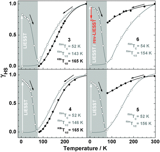
By irradiation at 519 nm at 5 K, the low-spin state can be converted to the high spin state, and this spin-state switching can be reversed to a certain degree by irradiation at 810 nm (reverse-LIESST, see below). Compound 5 in KBr shows less intense bands at 596 nm and 685 nm, whereas in films the intensity at 600 nm and 685 nm increases to the same level as in KBr. In Fig. 7 the high-spin fraction calculated by the method applied previously7,17 is plotted vs. the temperature. In the bulk material of 5 and 6 in KBr the spin transition is largely suppressed. On the other hand, all films show thermal SCO behaviour and exhibit the LIESST-effect by irradiation at 519 nm for 5 min at 5 K. For all systems, γHS values of ∼82–96% can be achieved. The critical LIESST-temperatures are TC = 52–54 K, which are 8–10 K higher than that for 2.5,7 The reverse-LIESST effect is demonstrated in 6 under irradiation at 810 nm for 30 min, leading to a decrease of γHS from 96 to 74%. The thermal spin transition of 4 is more gradual in the vacuum-deposited film than in the bulk material (cf.Fig. 3) which can be attributed to a decrease of cooperative interactions.14,18 This has already been noticed in our study of the parent compound [Fe(H2Bpz2)(phen)] (2).7 As a matter of fact, the thermal spin crossover of a film of 2 is very similar to that of 2 embedded in polystyrene (ESI,‡ Fig. S5). The observation of a spin transition in the films of 5 and 6 also appears to be due to a reduction of cooperative or intermolecular interactions which apparently “lock” these systems in the high-spin state in the crystalline bulk material.19
In order to obtain more information on the electronic states of 6 XA spectra at the iron L2,3 edges were recorded.9,20Fig. 8 shows the temperature variation for a thin film (∼4 ML) on HOPG (a) and a bulk material crimped in indium foil (b); room-temperature spectra are plotted in red and 80 K spectra in blue. At 300 K, the iron L3 edge exhibits a typical double-peak structure with maxima at 708.4 eV and 709.2 eV, indicative of HS-Fe(II).9,20 At 80 K, the intensity of the 708.4 eV peak decreases, and the peak at 709.2 eV shifts to 709.4 eV together with a satellite peak that shifts from 711.0 eV to 711.7 eV. There is still a significant contribution of the 708.4 eV peak, characteristic for the high-spin state. The thermal spin crossover thus is not complete. Nevertheless, the SCO is more pronounced in the thin film than in the bulk powder sample, in agreement with the results from optical absorption spectroscopy. High-spin fractions were determined by fitting measured spectra with theoretical spectra obtained by multiplet calculations (cf. ESI,‡ S6). In the thin film of ∼4 ML, the HS fraction determined in this way decreases from ∼100% at 300 K to about 58% at 80 K, whereas for the bulk sample, the HS fraction is reduced from 94% at 300 K to 73% at 80 K. From difference spectra we also conclude that the change of γHS is ∼2 times larger in the film than in the bulk material of 6. It must be stressed that Mössbauer and magnetic measurements (see above) showed no contribution of the LS state at 300 K. However, Moliner et al. reported a LS fraction of 15% in 2.5 In Fig. 9 the N-K XA spectrum of the thin film of 6 on HOPG, measured at 300 K, is shown along with the spectrum of the bulk material finely scratched onto an indium foil. The two spectra closely resemble each other, again confirming the integrity of the evaporated compound.
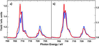 | ||
| Fig. 8 Temperature-dependent iron L2,3 XA spectra of 4 ML of 6 on HOPG (a) and bulk powder sample crimped in indium foil (b) at 300 K (red lines) and 80 K (blue lines). | ||
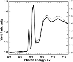 | ||
| Fig. 9 N-K XA spectrum of 4 ML of 6 on HOPG (black line) with respect to the bulk material finely scratched onto indium foil (grey dotted line) at 300 K. | ||
Raman spectroscopy of the bulk material and thin films
To further investigate the spin transition, temperature dependent resonance Raman spectra with excitation wavelengths of λexc = 514 nm and 647 nm were measured. In Fig. 10 the Raman spectra of 3–6 dispersed in KBr at 300 K and 25 K are shown. At 300 K, the high-spin spectra show numerous peaks for metal–ligand and interligand vibrations of the pyrazole and phenanthroline units. At 25 K, these peaks get more intense; moreover, a broad and intense band with maxima at 411 cm−1, 425 cm−1 and 444 cm−1 appears for 3 (green). Similar bands are observed for 4 (maxima at 408 cm−1, 433 cm−1 and 447 cm−1), 5 (maxima at 452 cm−1 and 495 cm−1) and 6 (maxima at 449 cm−1 and 470 cm−1).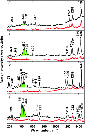 | ||
| Fig. 10 Resonance Raman (λexc = 647 nm) of 3 (a), 4 (b), 5 (c), 6 (d) at 300 K (red lines), 20 K (black lines) and electronic transition coloured in green. | ||
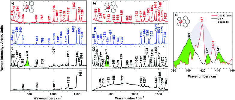
Raman spectra of a similar quality could not be obtained for the vacuum-deposited films of 3–6, in contrast to the parent compounds 1 and 2. Temperature-dependent Raman spectra of 1 and 2 recorded for the bulk material dispersed in KBr are shown in Fig. 11a and b (upper three traces) along with the corresponding thin-film spectra recorded at 25 K (bottom traces). Small differences between the 300 K spectra (high-spin; red) and the 100 K (low-spin; blue) are detectable; a full analysis of these data will be presented elsewhere. At 25 K (black traces) broad intense bands emerge at 460 cm−1 for 1 and at ∼420 cm−1 (maxima at 401, 426 and 441 cm−1) for 2 (green), in analogy to compounds 3–6 (Fig. 10). Importantly, these features are absent in vacuum-deposited films of 1 and 2 (bottom traces of Fig. 11). We attribute these bands to electronic Raman transitions. In the case of compound 2 the electronic transition obviously combines with vibrational modes of the high-spin state; i.e., peaks appearing at 417 and 434 cm−1 in the room temperature spectrum (Fig. 11b red) are present as dips in the 25 K spectrum (Fig. 11b, black). For further clarification Fig. 11c shows a Gaussian profile centred at 417 cm−1 representing the electronic Raman transition. It is seen that the 25 K spectrum exhibits minima at positions where the room-temperature spectrum (enlarged) has maxima.
Such antiresonance phenomena occur when transitions to a continuum of states are superposed with transitions to discrete levels.21 This appears to be the case for compound 2 as the electronic Raman band is much broader than the vibrational peaks. Similar considerations apply to compounds 3–6, exhibiting electronic Raman bands with complex band shapes as well (Fig. 10). For compound 1, on the other hand, no vibrational peaks are present in the region of the electronic Raman transition; therefore this band exhibits a conventional band shape without antiresonance dips (Fig. 11a, green).
To explain the observation of an electronic Raman effect in the crystalline bulk material we assume that excitation through the Raman laser populates the high-spin state and an electronic transition occurs within the 5T2g state split by low symmetry into a |ξ〉, |η〉 and |ζ〉 state.22 Real et al. reported a compressed octahedral geometry for 1 and 2 based on crystal structure determination.4 The effect of low-symmetry ligand fields and spin–orbit coupling on the magnetic behaviour of transition-metals with the 5T2g ground term has been reported.23 Electronic Raman transitions between low-lying electronic states have been detected for lanthanide and transition metal ions before, especially tetraphenylporphyrinatoferrate(III) complexes.24
Conclusions
In the present study we investigated the influence of methyl and chloro substituents on the spin transition of [Fe(H2Bpz2)2(phen)] (2) in the solid state and in films deposited from the gas phase. Importantly, thin film preparation is feasible for all compounds by thermal deposition, enlarging the library of iron complexes for physical vapour deposition.1,2,7,20,25 These systems thus offer the unique opportunity to investigate the thermal as well as light-induced SCO behaviour in the absence of solid-state effects such as cooperative or intermolecular interactions.A particularly spectacular example for this aspect is the behaviour of compound 6, which shows SCO in a vacuum-deposited film but remains in the high-spin state over almost the entire temperature range in the crystalline bulk material. Although we do not have direct information about the crystal structure of solvate-free 6, we assume that the persistence of the high-spin state in the solid state is due to the formation of dimers through π–π interactions between neighbouring 4,7-dimethyl-1,10-phenanthroline ligands which have been detected in the toluene solvate of 6 and in other [Fe(H2Bpz2)2(L)] complexes.12 If sufficiently strong these interactions can “lock” the system in the high-spin state. In microcrystalline powders of 6, these interactions are reduced. This allows an incomplete spin-transition to occur, as evidenced by optical and X-ray absorption spectroscopic measurements. In a vacuum-deposited film of 6 of several 100 nm thickness a full spin transition is observed, suggesting that the intermolecular interactions between the SCO molecules now are absent. On the other hand, for a film of ∼4 ML of 6 on HOPG the spin transition again becomes incomplete. We believe that this is an effect of the surface on the spin transition of this complex, as observed for other systems.10
A second hallmark of the [Fe(H2Bpz)2(L)] systems is the emergence of an electronic Raman transition at low temperature, as observed for compounds 1–6. This phenomenon, however, appears to be restricted to the crystalline bulk material because for the parent compounds 1 and 2 the corresponding bands are absent in vacuum-deposited films. As decomposition of 1 and 2 can be ruled out in the films,7 in analogy to compounds 3–6, we assume that the special packing of these complexes in the solid state and the emergence of electronic Raman transitions are connected with each other. Further investigation of this intriguing problem is underway.
Experimental
All reactions were carried out in dry solvents and under an inert atmosphere. Functionalized 1,10-phenanthroline, iron(II) perchlorate hydrate and solvents were purchased commercially and used as supplied. Potassium dihydrobis-pyrazolylborate K[H2Bpz2] and the complexes were prepared according to literature methods.4,15Synthesis of [Fe(H2Bpz2)2(4-methyl-1,10-phenanthroline)] (3)
To a solution of Fe[ClO4]2·6H2O (726 mg, 2 mmol) in methanol (10 mL) was added a solution of K[H2Bpz2] (744 mg, 4 mmol) in methanol (10 mL). The originated KClO4 precipitate was removed by filtration. A solution of 4-methyl-1,10-phenanthroline (388 mg, 2 mmol) in 10 mL methanol was added dropwise to the yellow Fe[H2Bpz2]2 solution. The solution was stirred for 15 min and a dark violet precipitate was collected, washed with methanol (20 mL), and dried under a stream of N2. Yield 786 mg; 72%. Elemental analysis calculated for C25H26B2FeN10: C, 55.20; H, 4.82; N, 25.75. Found: C, 54.93; H, 4.79; N, 25.53.Synthesis of [Fe(H2Bpz2)2(5-chloro-1,10-phenanthroline)] (4)
The method as reported for 3, using Fe[ClO4]2·6H2O (160 mg, 0.44 mmol), K[H2Bpz2] (164 mg, 0.88 mmol) and 5-chloro-1,10-phenanthroline (94.5 mg, 0.44 mmol), yields a violet precipitate of 4. Yield 155 mg; 62%. Elemental analysis calculated for C24H23B2ClFeN10: C, 51.07; H, 4.11; N, 24.82. Found C, 51.04; H, 3.98; N, 24.56.Synthesis of [Fe(H2Bpz2)2(4,7-dichloro-1,10-phenanthroline)] (5)
The method as reported for 3, using Fe[ClO4]2·6H2O (182 mg, 0.5 mmol), K[H2Bpz2] (186 mg, 1.0 mmol) and 4,7-dichloro-1,10-phenanthroline (125 mg, 0.5 mmol), yields a violet precipitate of 5. Yield 209 mg; 70%. Elemental analysis calculated for C24H22B2Cl2FeN10: C, 48.13, H, 3.70; N, 23.39. Found: C, 47.97; H, 3.67; N, 22.99.Synthesis of [Fe(H2Bpz2)2(4,7-dimethyl-1,10-phenanthroline)] (6)
The method as reported for 3, using Fe[ClO4]2·6H2O (295 mg, 0.8 mmol), K[H2Bpz2] (297 mg, 1.6 mmol) and 4,7-dimethyl-1,10-phenanthroline (170 mg, 0.8 mmol), yields a violet precipitate of 6. Yield 309 mg; 55%. Elemental analysis calculated for C26H28B2FeN10: C, 55.96; H, 5.06; N, 25.10. Found: C, 56.49; H, 5.20; N, 25.27. The crystals of 6·0.5 C7H8 for single crystal analysis were grown by slow diffusion of n-hexane into a toluene solution.Single crystal structure analysis
Data collections for 6·0.5 C7H8 were performed at three different temperatures using an imaging plate diffraction system (IPDS-2) from STOE & CIE with Mo-Kα-radiation (λ = 0.71073 Å). The structure solution was prepared by direct methods using SHELXS-97 and structure refinements were performed against F2 using SHELXL-97.26 All non-hydrogen atoms were refined anisotropic. The C–H and B–H H atoms were positioned with idealized geometry and refined isotropic with Uiso(H) = 1.2Ueq(C, B) (1.5 for methyl H atoms) using a riding model. The crystal structure contains an additional toluene molecule, which is disordered on a center of inversion. At room-temperature the disorder cannot be resolved and therefore, the data were corrected for disordered solvent using Squeeze in Platon but the toluene molecule was considered in the calculation of the molecular formula. At 200 and 110 K the disorder can be resolved and the toluene molecule was refined with a split model using restraints. CCDC 1054498 (6·0.5 C7H8 at 293 K), 1054497 (6·0.5 C7H8 at 200 K) and 1054497 (6·0.5 C7H8 at 110 K).XA-spectroscopy
The measurements were carried out in situ at a pressure of 8 × 10⁻¹⁰ mbar at the beamline UE56/2-PGM-1 of BESSY II. The photon flux at the sample position was about 1013 photons per s per cm2, with the energy resolution of the beamline set to 200 meV. XA spectra were recorded at the magic angle of 54.7 between the surface and the k vector of the linearly p-polarized X-rays. The absorption was measured in the total electron yield mode, where the sample drain current is recorded as a function of photon energy. The XA spectra were normalized with respect to a gold grid upstream to the experiment, and to the background signal from a clean HOPG substrate. The HOPG substrate (12 mm × 12 mm) with a mosaic spread angle (0.4 ± 0.1) was purchased from Structure Probe. A clean HOPG surface was obtained by cleaving away layers of the surface in a vacuum (10−6 mbar) using carbon tape. The bulk sample was prepared by finely scratching molecular powder onto indium foil. The thin film (4 ML) was prepared by evaporating the molecular powder from a tantalum Knudsen cell at about 460 K onto the substrate held at RT. The thickness of the film was monitored using a quartz microbalance during the evaporation.Other measurements
Elemental analyses were performed using a Euro Vector CHNS-O-element analyser (Euro EA 3000). Samples were burned in sealed tin containers by a stream of oxygen. IR spectra were recorded on a Bruker Alpha-P ATR-IR Spectrometer. The magnetic measurements were performed using a physical property measurement system (PPMS, Quantum Design) with a magnetic field strength of 1 T. Diamagnetic corrections were applied with the use of the tabulated Pascal's constants. Mössbauer measurements were recorded using a self-assembled spectrometer using standard transmission geometry. XRPD of the bulk material were recorded on a X'PERT PRO PANalytical instruments with a Göbel mirror and a PIXcel detector using Cu radiation. For Raman spectroscopic measurements a Dilor XY-Raman spectrometer (Horiba) was used with an Ar+/Kr+ mixed gas laser (Spectra Physics GmbH) operating at 647 and 514 nm. The compounds were crimped in KBr or evaporated as films on quartz discs or on Au/Ti/glass substrates (thickness several 100 nm) under the same conditions as reported in ref. 7. Au/Ti/glass substrates with a 50 Å titanium base layer and a 1000 Å evaporated gold film were purchased from EMF Corporation (Ithaca, NY). UV/Vis spectra were recorded using a Cary 5000 spectrometer in transmission geometry. For temperature dependence a CryoVac Kryostat with liquid nitrogen or helium cooling was used. For illumination experiments 3× LED Luxeon Typ LXML-PM01-0080 (519 nm) and 1× LED Roithner Laser Technik APG2C1-810 (810 nm) was used from Sahlmann Photochemical Solutions.Acknowledgements
The authors thank the Deutsche Forschungsgemeinschaft (DFG) for funding this research through CRC 677 (Kiel) and 658 (Berlin). U. Cornelissen, S. Pehlke and J. Pick are acknowledged for Raman, infrared and CHNS measurements, H. Lühmann and M. Rasmussen for magnetic measurements, W. von Osten for Mössbauer spectroscopy, S. Permien for XRPD and I. Jeß for X-ray single crystal measurements. A. Britton, D. Krüger, and M. Kohlmann are acknowledged for their support, and W. Mahler for his technical support during the beamtime sessions on BESSY II.Notes and references
- T. G. Gopakumar, F. Matino, H. Naggert, A. Bannwarth, F. Tuczek and R. Bernd, Angew. Chem., Int. Ed., 2012, 51, 6262 CrossRef CAS PubMed.
- T. Miyamachi, M. Gruber, V. Davesne, M. Bowen, S. Boukari, L. Joly, F. Scheurer, G. Rogez, T. K. Yamada, O. Ohresser, E. Beaurepaire and W. Wulfhekel, Nat. Commun., 2012, 3, 938 CrossRef CAS PubMed; M. Gruber, V. Davesne, M. Bowen, S. Boukari, E. Beaurepaire, W. Wulfhekel and T. Miyamachi, Phys. Rev. B, 2014, 89, 195415 CrossRef; G. Molnár, L. Salmon, W. Nicolazzi, F. Terki and A. J. Bousseksou, J. Mater. Chem. C, 2014, 2, 1360 RSC; O. Kahn and C. J. Martinez, Science, 1998, 279, 44 CrossRef; J. Dugay, M. Giménez-Marqués, T. Kozlova, H. W. Zandbergen, E. Coronado and H. S. J. van der Zant, Adv. Mater., 2015, 27, 1288 CrossRef PubMed.
- M. A. Halcrow, Spin-Crossover Materials, Properties and Applications, John Wiley & Sons, Ltd, New York, 2013 CrossRef PubMed; P. Gütlich, A. B. Gaspar and Y. Garcia, Beilstein J. Org. Chem., 2013, 9, 342–391 CrossRef PubMed.
- J. A. Real, M. C. Munoz, J. Faus and X. Solans, Inorg. Chem., 1997, 36, 3008 CrossRef CAS PubMed.
- N. Moliner, L. Salmon, L. Capes and M. C. Munoz, J. Phys. Chem. B, 2002, 106, 4276 CrossRef CAS.
- A. L. Thompson, A. E. Goeta, J. A. Real and M. C. Muñoz, Chem. Commun., 2004, 1390–1391 RSC.
- H. Naggert, A. Bannwarth, S. Chemnitz, T. von Hofe, E. Quandt and F. Tuczek, Dalton Trans., 2011, 40, 6364 RSC.
- T. Palamarciuc, J. C. Oberg, F. El Hallak, C. F. Hirjibehedin, M. Serri, S. Heutz, J.-F. Létard and P. J. Rosa, J. Mater. Chem., 2012, 22, 9690 RSC.
- T. G. Gopakumar, M. Bernien, H. Naggert, F. Matino, C. F. Hermanns, A. Bannwarth, S. Mühlenberend, A. Krüger, D. Krüger, F. Nickel, W. Walter, R. Berndt, W. Kuch and F. Tuczek, Chem. – Eur. J., 2013, 19, 15702 CrossRef CAS PubMed.
- B. Warner, J. C. Oberg, T. G. Gill, F. El Hallak, C. F. Hirjibehedin, M. Serri, S. Heutz, M.-A. Arrio, P. Sainctavit, M. Mannini, G. Poneti, R. Sessoli and P. Rosa, J. Phys. Chem. Lett., 2013, 4, 1546 CrossRef CAS; X. Zhang, T. Palamarciuc, J. F. Letard, P. Rosa, E. V. Lozada, F. Torres, L. G. Rosa, B. Doudin and P. A. Dowben, Chem. Commun., 2014, 50, 2255 RSC; A. Pronschinske, R. C. Bruce, G. Lewis, Y. Chen, A. Calzolari, M. Buongiorno-Nardelli, D. A. Shultz, W. You and D. B. Dougherty, Chem. Commun., 2013, 49, 10446 RSC.
- E. Ludwig, H. Naggert, M. Kalläne, S. Rohlf, E. Kröger, A. Bannwarth, A. Quer, K. Rossnagel, L. Kipp and F. Tuczek, Angew. Chem., Int. Ed., 2014, 53, 3019 CrossRef CAS PubMed.
- R. Kulmaczewski, H. J. Shepherd, O. Cespedes and M. A. Halcrow, Inorg. Chem., 2014, 53, 9809 CrossRef CAS PubMed.
- M. Milek, F. W. Heinemann and M. M. Khusniyarov, Inorg. Chem., 2013, 52, 11585 CrossRef CAS PubMed; M. Nihei, Y. Suzuki, N. Kimura, Y. Kera and H. Oshio, Chem. – Eur. J., 2013, 19, 6946 CrossRef PubMed; K. Katayama, M. Hirotsu, I. Kinoshita and Y. Teki, Dalton Trans., 2012, 41, 13465 RSC; J. Rudnik, H. Naggert, S. Schwarzer, F. Tuczek and I. Parchmann, CHEMKON, 2014, 21, 85 CrossRef PubMed.
- P. Gütlich, A. Hauser and H. Spiering, Angew. Chem., Int. Ed., 1994, 33, 2024 CrossRef PubMed.
- S. Trofimenko, J. Am. Chem. Soc., 1967, 89, 3170 CrossRef CAS.
- G. R. Desiraju and J. A. R. P. Sarma, Proc. – Indian Acad. Sci., Chem. Sci., 1986, 96(6), 599 CrossRef CAS.
- S. Schenker, A. Hauser and R. M. Dyson, Inorg. Chem., 1996, 35, 4676 CrossRef CAS.
- P. Chakraborty, M.-L. Boillot, A. Tissot and A. Hauser, Angew. Chem., Int. Ed., 2013, 52, 7139 CrossRef CAS PubMed.
- Correspondingly 5 and 6 undergo thermal SCO in homogeneous solution.
- M. Bernien, D. Wiedemann, C. F. Hermanns, A. Krüger, D. Rolf, W. Kröner, P. Müller, A. Grohmann and W. Kuch, J. Phys. Chem. Lett., 2012, 3, 3431 CrossRef CAS.
- U. Fano, Phys. Rev., 1961, 124, 1866 CrossRef CAS; U. Fano and J. W. Cooper, Phys. Rev., 1965, 137, 1364 CrossRef.
- E. I. Solomon, E. G. Pavel, K. E. Loeb and C. Campochiaro, Coord. Chem. Rev., 1995, 144, 369 CrossRef CAS; R. Zimmerman and H. Spiering, Phys. Status Solidi B, 1975, 67, 487 CrossRef PubMed.
- B. N. Figgis, J. Lewis and G. Webb, J. Chem. Soc. A, 1966, 422 RSC.
- L. Galich, H. Hückstädt and H. Homborg, J. Porphyrins Phthalocyanines, 1997, 1, 259 CrossRef CAS; B. J. Kennedy, K. S. Murray, P. R. Zwack, H. Homborg and W. Kalz, Inorg. Chem., 1986, 25, 2539 CrossRef; S. Sievertsen, H. Schlehahn and H. Homborg, Z. Anorg. Allg. Chem., 1993, 619, 1064 CrossRef PubMed.
- T. Mahfoud, G. B. Molnar, S. Cobo, L. Salmon, C. Thibault, C. Vieu, P. Demont and A. Bousseksou, Appl. Phys. Lett., 2011, 99, 053307 CrossRef CAS PubMed; S. Shi, G. Schmerber, J. Arabski, J.-B. Beaufrand, D. J. Kim, S. Boukari, M. Bowen, N. T. Kemp, N. Viart, G. Rogez, E. Beaurepaire, H. Aubriet, J. Petersen, C. Becker and D. Ruch, Appl. Phys. Lett., 2009, 95, 043303 CrossRef PubMed; B. Schäfer, C. Rajnak, I. Salitros, O. Fuhr, D. Klar, C. Schmitz-Antoniak, E. Weschke, H. Wende and M. Ruben, Chem. Commun., 2013, 49, 1098 RSC; I. Cimatti, S. Ninova, V. Lanzilotto, L. Malavolti, L. Rigamonti, B. Cortigiani, M. Mannini, E. Magnano, F. Bondino, F. Totti, A. Cornia and R. Sessoli, Beilstein J. Nanotechnol., 2014, 5, 2139 CrossRef PubMed.
- G. M. Sheldrick, Acta Crystallogr., 2008, 64, 112 CrossRef CAS PubMed.
Footnotes |
| † Dedicated to Dr Dénes Lajos Nagy on the occasion of his 70th anniversary. |
| ‡ Electronic supplementary information (ESI) available: Crystallographic data, XRD-powder patterns, and infrared spectra of bulk/film and XA spectra. CCDC 1054496, 1054497 and 1054498. For ESI and crystallographic data in CIF or other electronic format see DOI: 10.1039/c5tc00930h |
| This journal is © The Royal Society of Chemistry 2015 |

