 Open Access Article
Nature of Li2O2 and its relationship to the mechanisms of discharge/charge reactions of lithium–oxygen batteries
Yanan
Gao
 ac,
Hitoshi
Asahina
ab,
Shoichi
Matsuda
 ab,
Hidenori
Noguchi
 ac and
Kohei
Uosaki
 *ab
*ab
aCenter for Green Research on Energy and Environmental Materials, National Institute for Materials Science (NIMS), Namiki 1-1, Tsukuba 305-0044, Japan. E-mail: uosaki.kohei@nims.go.jp
bSoftBank-NIMS Advanced Technologies Development Center, NIMS, 1-1 Namiki, Tsukuba, Ibaraki 305-0044, Japan
cGraduate School of Chemical Sciences and Engineering, Hokkaido University, Sapporo 060-0810, Japan
First published on 19th March 2024
Abstract
Lithium–air batteries (LABs) are considered one of the most promising energy storage devices because of their large theoretical energy density. However, low cyclability caused by battery degradation prevents its practical use. Thus, to realize practical LABs, it is essential to improve cyclability significantly by understanding how the degradation processes proceed. Here, we used online mass spectrometry for real-time monitoring of gaseous products generated during charging of lithium–oxygen batteries (LOBs), which was operated with pure oxygen not air, with 1 M lithium bis(trifluoromethanesulfonyl)imide (LiTFSI) tetraethylene glycol dimethyl ether (TEGDME) electrolyte solution. Linear voltage sweep (LVS) and voltage step modes were employed for charge instead of constant current charge so that the energetics of the product formation during the charge process can be understood more quantitatively. The presence of two distinctly different types of Li2O2, one being decomposed in a wide range of relatively low cell voltages (2.8–4.16 V) (l-Li2O2) and the other being decomposed at higher cell voltages than ca. 4.16 V (h-Li2O2), was confirmed by both LVS and step experiments. H2O generation started when the O2 generation rate reached a first maximum and CO2 generation took place accompanied by the decomposition of h-Li2O2. Based on the above results and the effects of discharge time and the use of isotope oxygen during discharge on product distribution during charge, the generation mechanism of O2, H2O, and CO2 during charging is discussed in relation to the reactions during discharge.
1. Introduction
Rechargeable batteries are considered to play key roles in a future sustainable, carbon neutral society based on renewable energy as energy sources for fossil fuel-free transportation and as energy storage devices for stabilizing the temporal/spatial variation of the power generation by solar cells, windmills, and other renewable/natural energy sources.1–5 There are, however, many issues to be considered for the widespread use of rechargeable batteries such as energy/power densities, cycle/calendar life, cost, and resource constraints.5–10Lithium–air batteries (LABs) have attracted significant interest over the past decades because of their very high theoretical energy density and transition metal-free positive electrode (cathode during discharge).11–22 Oxygen from air and Li metal are the active materials for the cathode and anode, respectively, for LABs with the cell reaction of 2Li + O2 ⇄ Li2O2. Usually, porous carbon is used as a positive electrode material to accommodate Li2O2 generated during discharge.23–28 There are many critical problems to be solved before LABs can be used as a practical device. Many components of air such as water, CO2, and even N2, are harmful to LAB operation29–32 and, therefore, most fundamental studies have been carried out for lithium oxygen batteries (LOBs), which use pure dry O2 instead of air.29,33,34 Even LOBs have serious problems such as low cyclability and stability mainly due to the degradation of the positive electrode (carbon) and electrolyte solution, and the degradation/dendrite formation of the negative Li metal electrode.35–41 To improve the cyclability/stability, it is essential to clarify the mechanism of LOB degradation.42,43 While the degradation/dendrite formation of Li metal electrode is a common issue of all next generation batteries using Li metal as a negative electrode (anode during discharge), degradation of the positive electrode and electrolyte is more serious in LOBs than in other next generation batteries because Li2O2, the product at the cathode during discharge of the LOB, is an insulator, which requires a high overpotential to be decomposed during charge, and active oxygen species such as O2− and 1O2 generated during discharge and charge attack and degrade the electrolyte and carbon positive electrode.35–39 Many efforts have been made to investigate the degradation mechanism at the positive electrode using various techniques such as surface enhanced Raman scattering,12,36,44 electrochemical quartz crystal microbalance,45 X-ray diffraction (XRD),14,21,25,36,42,46,48,49 X-ray photoelectron spectroscopy (XPS),47,48 and mass spectrometry.21,36,40,42,49–55
Reaction sites for the formation of Li2O2 have been discussed for a long time but still no agreement has been reached. Recently we reported that a very long (∼80 µm) Li2O2 nanowire can be grown at a gold electrode covered with single layer graphene (SLG) and the reaction site is the defect sites of SLG on the Au electrode/Li2O2 interface based on Raman analysis with isotopic 18O2.56 On the other hand, Nakanishi and his colleagues suggested that Li2O2 grew at the electrolyte/Li2O2 interface of a surface modified carbon paper cathode during discharge based on the results of nano-SIMS analysis and that there exist two types of Li2O2; one is formed close to the electrode in the earlier stage of discharge and is more difficult to be oxidized and the other is formed in the latter stage of discharge covering the Li2O2 which is formed earlier and is more easily oxidized.57 More recently, Tan et al. suggested that Li2O2 deposition takes place both at the cathode/Li2O2 interface and at the electrolyte/Li2O2 interface after the initial deposition of insulating Li2O2 during discharge.58,59
The origin of CO2 is also a very important issue for understanding the degradation mechanism.60–66 Many papers have mentioned that CO2 is originated from carbonate and carboxylate species such as Li2CO3, HCO2Li, and CH3CO2Li, which are formed by the attack of active oxygen species on electrolyte and/or carbon during discharge/charge processes.64–66 McCoskey et al. suggested that about 50% of CO2 are originated from carbonate, which is generated by the oxidation of carbon positive electrode, based on the results obtained using a carbon positive electrode made of 13C.63
In the present work, we used online mass spectrometry for real time monitoring of generated gaseous products during charging of LOBs with 1 M lithium bis(trifluoromethanesulfonyl)imide (LiTFSI) tetraethylene glycol dimethyl ether (TEGDME) electrolyte solution. Discharge of LOBs was carried out for various time periods and under the flow of two isotope O2 gas, 16O2 and 18O2. The O2 generation during charging showed the presence of two distinctly different types of Li2O2, one being decomposed in a wide range of relatively low cell voltages (2.8 – ca. 4.1 V) (l-Li2O2) and the other being decomposed at cell voltages higher than ca. 4.1 V (h-Li2O2) during charging. H2O and CO2 generation took place at relatively low voltage accompanied by the decomposition of l-Li2O2 and at higher cell voltage with the decomposition of h-Li2O2, respectively. Based on the above results and the effects of discharge time and the use of isotope oxygen during discharge on product distribution during charge, the generation mechanism of O2, H2O, and CO2 during charge is discussed in relation to the reactions during discharge.
2. Experimental section
2.1. Materials
A CNT-based porous carbon sheet (KJCNT, thickness 50 µm) donated by KJ Specialty Paper was used as a positive electrode as it has more uniform and simpler pore structures than Ketjenblack and carbon nanotube-based positive electrodes which we usually use for more practical cells.54,55 The KJCNT sheet was cut into discs with a diameter of 16 mm, baked in a tube furnace for 3 h at 900 °C under an Ar atmosphere, then transferred to a dry room for cell assembly. Disk-shaped lithium foil (thickness 200 µm, diameter 16 mm) obtained from Honjo Metal was used as a negative electrode. Battery grade TEGDME and LiTFSI were obtained from Kishida Chemical and used as received. 1 M LiTFSI TEGDME prepared in a super dry room was used as an electrolyte solution. The water content in electrolyte solutions was around 40 ppm as measured by using a Karl Fischer Moisture Meter (Model: CA-21; Mitsubishi Chemical Analytech). A polyethylene (PE) membrane separator (thickness 20 µm) was obtained from W-scope and was cut into a disc with a diameter of 19.5 mm and then dried in a vacuum oven for 10 h at 40 °C before use. A stainless steel mesh (thickness 200 µm, diameter 16.7 mm, aperture ratio 73%) was obtained from Hohsen. Isotope 18O2 gas (purity ≥ 98 atom%) was purchased from Taiyo Nippon Sanso.2.2. Cell assembly and measurement system
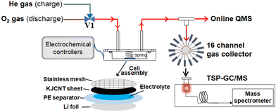
Fig. 1 shows the experimental set up for the gas analysis during discharge and charge.50 A lithium–oxygen cell was assembled in a stainless steel container (inner diameter: 45 mm, inner depth: 15 mm) with a lid equipped with a gas inlet and outlet by stacking Li metal foil, a polyethylene membrane separator, on top of which 15 µL of the 1 M LiTFSI TEGDME solution was placed as uniformly as possible, a KJCNT sheet, a stainless steel mesh as a current collector for the positive electrode, and a conductive spring coil, which provided the cell assembly with a pressure of 35 kPa as shown in Fig. 1. The apparent electrode area was 2 cm2. The assembly was carried out in a dry-booth (dew point less than −90 °C) in a dry room (dew point less than −60 °C).The cell was connected to an inlet gas line with a three-way Swagelok valve, V1, to select O2 and He gas during discharge and charge, respectively, electrochemical controllers (a charge/discharge system: HJ1020mSD8, Hokuto Denko and an electrochemical measurement system: HZ-7000, Hokuto Denko), and an outlet mass analysis line, which had two branch lines; one to a mass spectrometer (Canon Anelva Quadrupole Mass Spectrometer M-401GA-DM) through a capillary tube (internal diameter: 0.05 mm, length: 4 m) for online real time analysis and the other to a gas collector for post TSP-GC/MS analysis of organic products, the results of which are not discussed in this study.
2.3. Analysis methods
After the cell was connected to the measurement system, the cell was purged by flowing O2 at 2 cc min−1 for 2 h and then constant current discharge was carried out under O2 flow at 2 cc min−1 by using the discharge/charge system with a current density of 0.4 mA (0.2 mA cm−2) for 10 h or until reaching the cut-off voltage of 2 V. After the discharge was completed, the cell was set to open circuit and the inlet gas was switched from O2 to He. O2 in the cell was totally exchanged by He by flowing He by 20 cc min−1 for 90 min. The flow rate of He gas was then reduced to 5 cc min−1 and online mass spectrometry for mass numbers (m/z) between 12 and 90 was started. After 30 min He flow at OCP to stabilize the background mass level, the charge was performed under constant current (0.4 mA (0.2 mA cm−2)) for 10 h or until reaching the cut-off voltage of 4.8 V using the discharge/charge system, linear voltage sweep (LVS: 0.05 mV s−1 up to 4.8 V) using the potentiostat/galvanostat, or voltage step using the potentiostat/galvanostat. When the potentiostat/galvanostat was used, the carbon positive electrode was connected to the working electrode terminal and Li metal negative electrode was connected to both the counter and reference electrode terminals of the potentiostat/galvanostat so that the voltage applied to the cell was equivalent to the potential of the carbon electrode with respect to that of the Li electrode.3. Results and discussions
3.1. Constant current discharge/charge curves and mass signals during charge
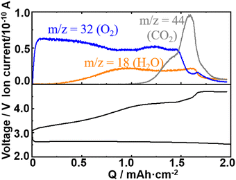
Fig. 2 shows the typical 1st discharge and charge curves (bottom panel) and ion currents for m/z = 18 (H2O), 32 (O2), and 44 (CO2) as a function of charge of the present cell configuration obtained with a constant current of 0.2 mA cm−2.As already reported by many groups including ours for various carbon positive electrodes, while the discharge voltage was relatively constant with a small overpotential up to 2 mA h cm−2 of discharge, the voltage increased significantly with several inflection points during charge, showing several processes with different redox potentials were involved in the charge process. The charge dependencies of the signals of m/z = 18 (H2O), 32 (O2), and 44 (CO2) were essentially the same as those reported in our previous papers,50 although the previous result was for a LOB with NO3−/Br− dual mediators and a Ketjenblack positive electrode. The charge dependence of the mass signal for O2 (m/z = 32) is not simple. The signal of m/z = 32 increased sharply as the charge started, reached a peak, and declined but then increased and decreased again despite the constant current flow, showing that the current efficiency for the oxidation of Li2O2, i.e., the formation of O2, varied during the charge in a complex manner. It seems the increase and decrease of the signal of m/z = 32 (O2) were related to the variations of signals of m/z = 18 (H2O) and 44 (CO2), suggesting that the variation of the current efficiency for the oxidation of Li2O2 was affected by the generations of H2O and CO2.
3.2. Behaviours of current and mass signals during LVS charge from OCP to 4.8 V after constant current discharge
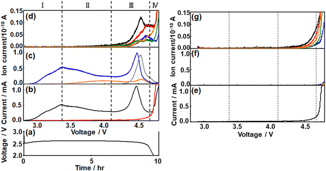
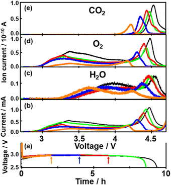
To understand the charge process more quantitatively, the charge was performed under LVS instead of constant current.49,60,67–69After constant current discharge (0.2 mA cm−2) for 9.6 h (cut-off voltage of 2 V as shown in Fig. 3(a)), the cell voltage was scanned from OCP, i.e., 2.8 V, to 4.8 V with a scan rate of 0.05 mV s−1 and current and online mass signals were recorded simultaneously. Fig. 3(b) shows the current (black line) as a function of the voltage. Current increased immediately as the voltage started to be scanned from OCP and reached a maximum at 3.36 V. It decreased gradually after the 1st maximum, reached the 1st minimum at 4.15 V, increased again to reach the 2nd maximum at 4.46 V, decreased to reach the 2nd minimum at 4.66 V, and then increased again. The second current peak declined sharply with rather symmetric shape. The current–voltage relation obtained after discharge can be divided into four regions; Region I: up to the 1st maximum (∼3.36 V), Region II: from the 1st maximum to the 1st minimum (3.36–4.15 V), Region III: from the 1st minimum to the 2nd minimum (4.15–4.66 V), and Region IV: from the 2nd minimum (4.66–4.8 V, i.e., final current increase).
The current response of the same cell configuration but without discharge under LVS with the scan rate of 0.05 mV s−1 is also shown in Fig. 3(b) (red line) and Fig. 3(e). In this case, the current was very small compared with that observed in the discharged cell (black line in Fig. 3(b)) up to 4.15 V (in Regions I and II of the discharged cell), started to increase from around 4.15 V, first gradually and then significantly in the potential region corresponding to Region III and Region IV, respectively, of the discharged cell. The current observed at the cell without discharge should be due to the direct anodic decomposition of the components of the electrolyte solution, TEGDME and LiTFSI. It became larger than that in the discharged cell when the voltage became more than ca. 4.7 V.
These results suggest that the current in the discharged cell in Region I–III was mostly due to the anodic oxidation of discharged products, mainly Li2O2, with a slight contribution of the direct electrochemical decomposition of the electrolyte solutions and that in Region IV was almost due to the direct electrochemical anodic decomposition of the electrolyte solutions.
The signal of m/z = 32 (O2) behaved similarly to the current and two maxima were observed. It increased immediately as did the current when the voltage scan was started and reached a maximum at 3.36 V (Region I). The signals of m/z = 18 (H2O) and m/z = 44 (CO2) were not significant in Region I. The major reaction in Region I is Li2O2 → 2Li+ + O2 + 2e−.
In Region II, the O2 mass signal (m/z = 32) decreased gradually after the 1st maximum as did the current but declined more rapidly than the current and reached a minimum at 4.15 V. A steeper decline of the O2 mass signal than the current means a decrease of the current efficiency for O2 generation by Li2O2 → 2Li+ + O2 + 2e− in this region. The H2O mass signal (m/z = 18) started to increase just after the 1st maxima of current and O2 signal where the current efficiency for O2 generation started to decrease, suggesting the H2O formation is responsible for the decrease of the current efficiency for oxygen generation, i.e., Li2O2 oxidation. The plausible source of H2O generation is LiOH with the reaction of LiOH → Li+ + 1/2H2O + 1/4O2 + e− (ca. 3.4 V).66 LiOH can be generated during discharge.50 The mass signal due to CO2 (m/z = 44) was not significant in Region II.
In Region III, the O2 signal increased again after the minimum at 4.15 V and reached a maximum at 4.48 V, which is 20 mV more than the position of the 2nd current peak, and decreased as current but more rapidly. This suggests the presence of another type of Li2O2, which is more difficult to oxidize than Li2O2 oxidized in Region I and II. The H2O signal declined very slightly with voltage and started to increase at ca. 4.4 V to reach a maximum at ca. 4.55 V, which is more than the peak positions of the current (4.46 V) and O2 (m/z = 32) signal (4.48 V). The CO2 signal (m/z = 44) started to increase at 4.15 V, where the current and the O2 signal started to increase again, and reached a maximum at ca. 4.53 V, which was more than the peak positions of the current and O2 signal but was slightly less than that of the H2O peak. The plausible source and reaction of CO2 generation are Li2CO3 and Li2CO3 → 2Li+ + CO2 + 1/2O2 + 2e− (ca. 3.8 V), respectively.66
Thus, Li2O2 was decomposed in Region I, II, and III and the presence of two distinct O2 signal peaks (3.36 V and 4.48 V) shows that there existed at least two types of Li2O2, the one oxidized at lower voltages (in Regions I and II and some in Region III: l-Li2O2) and the other oxidized at higher voltages (Region III: h-Li2O2) as suggested by several previous reports.70–73 While l-Li2O2 was oxidized in a wide range of voltages with a very broad peak (Region I and II), h-Li2O2 was oxidized in a relatively narrow range of voltages with a rather sharp symmetric peak with full width at half maximum of ca. 0.14 V. These results suggest that the natures and oxidation mechanisms of l-Li2O2 and h-Li2O2 were quite different. While l-Li2O2 was energetically distributed very widely with the required oxidation potentials from 2.8 V to 4.4 V or more, the energetic states of h-Li2O2 were rather sharp with an oxidation potential of around 4.5 V.
In Region IV, the mass signals of O2, H2O, and CO2 declined monotonously, although the current increased again rapidly at potentials more positive than 4.66 V. Instead, signals related to organic molecules derived from TEGDME such as m/z = 29, 31, 45, and 60 became significant in this region as shown in Fig. 3(d). These results agreed with the above suggestion that the current of the discharged cell in Region IV was mainly due to the direct electrochemical decomposition of the electrolyte solutions.
The contribution of the direct electrochemical decomposition of the electrolyte solutions to the mass signals – voltage relationships of the discharged cell can be evaluated by comparing with those of the same cell configuration but without discharge obtained under LVS with the scan rate of 0.05 mV s−1 shown in Fig. 3(f) and (g). At the cell without discharge, the current started to increase from around 4.15 V and increased gradually and significantly in the potential region corresponding to Region III and Region IV, respectively, of the discharged cell as already mentioned (Fig. 3(b) and (e)). Mass signals related to organic molecules derived from TEGDME such as m/z =29, 31, 45, and 60 (Fig. 3(g)) increased accordingly but those of m/z = 18, 32, and 44 (Fig. 3(f)) were almost negligible compared with that of the discharged cell in Regions I–III. These results confirm that the products detected in the discharged cell in Region III were mainly due to the anodic oxidation of discharged products, mainly Li2O2, with a slight contribution of the direct electrochemical anodic decomposition of the components of the electrolyte solution, TEGDME and LiTFSI, and those in Region IV were almost due to the direct electrochemical anodic decomposition of the electrolyte solution, TEGDME and LiTFSI, as already suggested based on current–voltage relationships.
Contribution of various oxidation reactions on current during LVS charge of the discharged cell
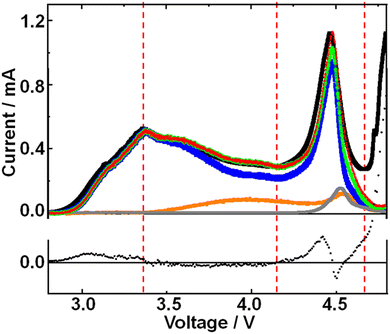
As mentioned above, after the 1st peak, the O2 mass signal declined steeper than the current with potential. This can be seen more clearly in Fig. 4 where partial current due to O2 generation, which was obtained by fitting the voltage dependence of O2 mass signal normalized at the 1st peak, was plotted (blue line) along with current (black line) as a function of voltage. Although there existed a slight time delay of partial current corresponding to O2 generation relative to current because of the delay between generation and mass detection of O2, total current and partial current due to O2 generation are matched reasonably well up to the 1st peak.After the 1st peak, the partial current (blue line) due to O2 generation became less than the total current (black line). Since the H2O signal increased in this region as mentioned above, a plausible reason for this discrepancy between the measured current and partial current due to O2 generation is the partial current due to H2O generation, which was evaluated by utilizing the voltage dependence of H2O mass signal to minimize the difference. Now the sum (green line) of the partial current due to O2 generation (blue line) and that of H2O generation (orange line) is in good agreement with the measured current in Region II. Thus, the decline of O2 generation efficiency after the 1st maximum (in Region II) is well explained by the current used for the generation of H2O.
In Region III, the difference between the measured current and the sum of partial current due to O2 generation and H2O generation became apparent. One reason is the delay of mass detection but even the peak height of the sum of the partial currents was smaller than the measured current. The discrepancy was minimized by taking into account the partial current due to CO2 generation (gray line), which was evaluated by utilizing the voltage dependence of the CO2 mass signal to minimize the difference. The sum (red line) of the partial currents due to O2 generation (blue line), H2O generation (orange line), and CO2 generation (gray line) is now in reasonable agreement with the measured current in Region III up to 4.66 V.
In Region IV or at higher voltages (more positive potentials of KJCNT electrode), the contributions of O2, H2O, and CO2 generation to current were minimal and the current was dominated by direct anodic decomposition of electrolyte solution as mentioned before.
Thus, anodic current is solely due to O2 generation by Li2O2 oxidation in Region I, O2 generation by Li2O2 oxidation and H2O generation possibly by LiOH oxidation in Region II, O2 generation mainly by Li2O2 oxidation, H2O generation possibly by LiOH oxidation, and CO2 generation mainly by Li2CO3 oxidation in Region III, and direct anodic oxidation of electrolyte solution in Region IV.
Behaviours of current and mass signals during charge by potential steps
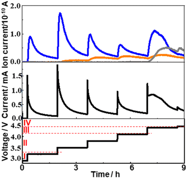
To see how the generation of O2, H2O, and CO2 proceeded, voltage step experiments were also performed.Fig. 5 shows the responses of current (middle panel) and signal intensities of m/z = 18 (orange), 32 (blue), and 44 (gray) when voltage steps were applied with the sequence shown in the bottom panel (300 mV voltage step and 6000 s stay). Since the background signal of m/z = 18 (H2O) was rather high (∼1.5 × 10⁻¹¹ A), the data shown in the figure are background corrected.
When the voltage was stepped from 2.9 V to 3.2 V (within Region I), 3.2 V to 3.5 V (Region I to Region II), 3.5 V to 3.8 V (within Region II), and 3.8 V to 4.1 V (within Region II) and kept at a given value for 6000 s, the current increased sharply and declined monotonously with time. The time dependence of mass signal for O2 (m/z = 32) was similar to that of current in these cases, although there existed some delay in the rising portion of oxygen generation compared to the current rise. It is interesting to note that both current and O2 signal became small after 6000 s but they increased significantly again when the next potential step was applied. This means that there existed Li2O2 which cannot be oxidized at a given potential, for example at 3.5 V, but can be oxidized at higher voltages, for example at 3.8 V. The increase of the H2O signal (m/z = 18) was also observed when these voltage steps were applied except for the voltage step from 2.9 V to 3.2 V (within Region I) as expected from the LVS (Fig. 3). The time dependence of the H2O signal was, however, quite different from those of the current and O2 signal. It increased very slowly upon the voltage step and declined very slightly after a peak. No significant change in the CO2 signal (m/z = 44) was observed when these voltage steps were applied as expected from the LVS (Fig. 3).
When the voltage was stepped from 4.1 V to 4.4 V (Region II to Region III), the current–time relationship was quite different from those observed in other voltage step cases reported above. After the current spike due to double layer charging, the current increased and then decreased again but not monotonously, showing rather complex processes took place in this case. The behaviour of the O2 signal was also quite different from those observed in other voltage step cases. Although it increased upon potential step and then declined as in other potential step cases, the decline was not monotonous but with a shoulder. The time dependencies of the current and the O2 signal can be deconvoluted with two waves; initial oxidation of l-Li2O2 (simple decay) followed by the oxidation of h-Li2O2 (complex curve). Thus, while only l-Li2O2 was oxidized when the voltage step was up to 4.1 V, both l-Li2O2 and h-Li2O2 were oxidized, first l-Li2O2 oxidation followed by h-Li2O2 oxidation, when the voltage was stepped to 4.4 V, corresponding to the 1st and the 2nd peak in the LVS (Fig. 3). These results support the conclusion drawn from LVS measurement that the natures (energetics) and the oxidation mechanisms of l-Li2O2 and h-Li2O2 were different. The behaviour of the m/z = 18 (H2O) signal was similar to those observed in other voltage step cases as it increased very slowly upon the voltage step and declined very slightly after a peak. The m/z = 44 (CO2) signal increased corresponding to this voltage step but in a rather complex way and declined after a peak as in the h-Li2O2 oxidation. This behaviour shows that the generation of CO2 was associated with h-Li2O2 oxidation.
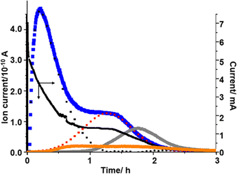
The presence of two different types of Li2O2 and the relationship between Li2O2 oxidation (O2 generation) and the generation of H2O and CO2 can be clearly seen when voltage was stepped from OCP (2.8 V) to 4.4 V, which was close to the 2nd maximum of the signal of m/z = 32 (O2) observed in the LVS (Fig. 3), as shown in Fig. 6.
The current increased sharply and declined but then reached a plateau at ca. 0.9 h, and then decreased again.
The signal of m/z = 32 (O2) increased upon voltage step but much more slowly compared with the current, reached a maximum at ca. 0.2 h, then declined, reached a plateau at ca. 1h, and then decreased again. This behaviour can be understood by considering the oxidation of Li2O2 corresponding to the 1st and 2nd peaks in the LVS (Fig. 3). The time dependence of the signal m/z = 32 (O2) can be deconvoluted into two peaks, the first peak being the one with a maximum at ca. 0.2 h and the 2nd peak represented by a Gaussian curve with a maximum at ca. 1.2 h as shown by dotted lines (black for the first peak and red for the second peak) in Fig. 6, although more accurate fitting requires the contribution of oxygen generation accompanied with the generation of H2O (e.g., LiOH → Li+ + ½H2O + ¼O2 + e−: ca. 3.4 V) and CO2 (e.g., Li2CO3 → 2Li+ + CO2 + ½O2 + 2e−: ca. 3.8 V). The integrated amount of the 2nd oxygen peak based on the fitting was in good agreement with that obtained in the LVS as shown in Table 1.
| Integrated current (charge)/mA h | Integrated mass signal (ion current)/10−10 A h | |||||
|---|---|---|---|---|---|---|
| m/z = 32 (O2) | m/z = 18 (H2O) | m/z = 44 (CO2) | ||||
| 1st | 2nd | Total | ||||
| LVS | 3.88 | 2.08 | 1.17 | 3.25 | 0.524 | 0.761 |
| Step to 4.4 V | 3.73 | 2.15 | 1.12 | 3.27 | 0.406 | 0.702 |
Thus, it is confirmed that there existed two types of Li2O2, one oxidized more easily than the other. The first type of Li2O2 (l-Li2O2) is oxidized at lower voltages in the LVS (Fig. 3) and in sequential step (Fig. 5) modes, and earlier when the voltage was stepped to and kept at 4.4 V where both types of Li2O2 can be oxidized (Fig. 6). These results also show that Li2O2, which corresponded to the 2nd oxygen peak in the LVS (h-Li2O2), was oxidized after the oxidation of Li2O2, which corresponded to the 1st oxygen peak in the LVS (h-Li2O2), which was completed in all charge modes.
The m/z = 18 (H2O) signal started to increase at around 0.2 h, which was close to the position of the 1st oxygen peak, increased rather slowly, reached a broad maximum at ca. 0.75 h, then declined and increased slightly, reached the 2nd maximum at ca. 1.6 h, and then decreased slowly. This behaviour is similar to that of H2O generation in the LVS and sequential step modes. The integrated amount of mass signal of H2O was in reasonable agreement with that obtained in the LVS measurement as also shown in Table 1.
The m/z = 44 (CO2) signal started to increase at around 1 h when the 1st oxygen generation was almost completed, reached a maximum at ca. 1.8 h, and then declined. The integrated amounts of the signal of m/z = 44 were in good agreement with that obtained in the LVS measurement as also shown in Table 1. It must be stressed that CO2 generation started when the oxidation of the first type of Li2O2 corresponding to the 1st oxygen peak in the LVS was completed and the second type of Li2O2 corresponding to the 2nd oxygen peak in the LVS was started as were the cases in the LVS (Fig. 3) and sequential step (Fig. 5) modes.
3.4. Effect of discharge time on the behaviours of current and mass signals during LVS charge
To further understand the relationship between O2 generation (Li2O2 oxidation) and the generations of H2O and CO2, time (voltage) dependencies of current and signal intensities of m/z = 18 (H2O), 32 (O2), and 44 (CO2) during LVS charge (0.05 mV s−1) were obtained after the constant current (0.2 mA cm−2) discharge of various time durations.Fig. 7 shows the results for the cells with discharge times of 2 (orange), 4 (blue), 6 (red), 8.8 (green), and 9.6 h (black). It is clear that as the discharge time increased, both current and mass signals increased and the positions of the 2nd current peak, the 2nd peaks of mass signals of m/z = 18 and 32, and the peak of mass signal of m/z = 44 shifted to higher voltages.
Fig. 8 shows the integrated amounts of current (=charge) and mass signals of m/z = 18, 32, and 44, which are normalized by the values of corresponding signals obtained for 9.6 h discharge. Except for the m/z = 18 (H2O) signal, integrated amounts are linearly increased with the discharge time. These results suggest that some species, which were converted to H2O during charge, i.e., LiOH, was preferentially formed in the earlier stage of discharge with residual water as LiOH formation is thermodynamically more favoured than Li2O2 formation if water is present.66
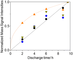 | ||
Fig. 8 Discharge time dependencies of integrated signal intensities, i.e., current ( ), and ion current of m/z = 18 ( ), and ion current of m/z = 18 ( ), 32 ( ), 32 ( ), and 44 ( ), and 44 ( ), normalized by those of 9.6 h discharge. ), normalized by those of 9.6 h discharge. | ||
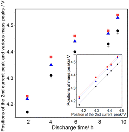
Fig. 9 shows the discharge time dependencies of the positions of the second current peak (+), the second peak of m/z = 18 ( ), the second peak of m/z = 32 (●), and the peak of m/z = 44 (
 ).
).
All peaks shifted positively with discharge time as mentioned above. The positions of the peaks are: the second current peak ≈ the second peak of m/z = 32 < the peak of m/z = 44 < the second peak of m/z = 18 in all the cases. The positions of the second peaks of m/z = 18 and 32 and the peaks of m/z = 44 are linearly related to the positions of the second current peak for different discharge times (inset of Fig. 9), showing the relative positions of these peaks are constant regardless of discharge time with ca. 60 mV and 45 mV differences between the m/z = 32 and 18 signals and m/z = 32 and 44 signals, respectively. These results suggest that the generation of CO2 proceeded not at potentials more positive than a unique potential such as the redox potential of Li2CO3 which is about 3.8 V,66,74 but when the oxidation of Li2O2 corresponding to the 2nd oxygen peak proceeded, supporting the above suggestion that the source of CO2, which is most probably Li2CO3 generated during discharge, was present at the same sites as the Li2O2 corresponding to the 2nd oxygen peak.
3.5. Source of O atoms in O2, H2O, and CO2 generated during LVS charge evaluated by the effect of two types of isotope oxygen gas used during discharge
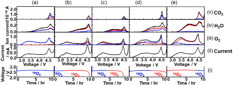
An oxygen atom in the charge products, O2, H2O, and CO2 can be from O2 gas, TEGDME, and residual H2O in the cell during discharge. By flowing the isotope oxygen gas, 16O2 or 18O2, during discharge and analysing the total fractions of 16O and 18O isotopes in the charge products, O2, H2O, and CO2, and voltage dependencies of the fractions of isotopes in O2, H2O, and CO2 during charge should provide useful information to understand the details of not only the growth mechanism of Li2O2 as studied in previous studies,56,70,71 but also the mechanisms through which the source compounds of the H2O and CO2, charge products, are generated during discharge.Fig. 10 shows mass signals (ion currents) corresponding to (iii) O2, (iv) H2O, and (v) CO2, and (ii) currents for various cells with the constant current discharge of 0.4 mA (0.2 mA cm−2) under various isotope O2 gas flow conditions as shown in the bottom panel (i). The red, blue, and black lines are of the ion currents (mass signals) related to 16O, 18O, and 16O + 18O, respectively. In the case of O2, the sum of the ion currents of m/z = 32 (16O16O) and half of the ion currents of m/z = 34 (16O18O) are taken as the ion currents due to the contribution of 16O in O2 and the sum of half of the ion currents of m/z = 34 and the ion currents of m/z = 36 (18O18O) are taken as the ion currents due to the contribution of 18O in O2. In the case of H2O, while the ion currents of m/z = 20 were taken as the ion currents due to 18O (H218O), the ion currents due to 16O (H216O) were obtained using the ion currents of m/z = 18 but after the contribution of 18O was corrected by considering the fragmentation of H218O (m/z = 20), 16O18O, 18O2, C16O18O, and C18O2 to 18O (m/z = 18). In the case of CO2, the sum of the ion currents of m/z = 44 (C16O16O) and half of the ion currents of m/z = 46 (C16O18O) are taken as the ion currents due to CO2 with 16O contribution and the sum of half of the ion currents of m/z = 46 and the ion currents of 48 (C18O18O) are taken as the ion currents due to CO2 with 18O contribution. The natural abundance of 18O in “16”O2 gas and the concentrations of 16O impurities in “18”O2 were taken into account in all the analysis and, in addition, the natural abundances of 13C was taken into account for the CO2 analysis.
The relationships between the fraction of 18O in the O2 gas flow during discharge and those in O2, H2O, and CO2 generated during charge were investigated. Fig. 11 shows the fractions of 18O in total amounts of O2, H2O, and CO2 generated during charge as a function of the fraction of 18O in O2 gas flow during discharge.
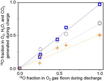 | ||
Fig. 11 Fractions of 18O in O2 ( ), H2O ( ), H2O ( ), and CO2 ( ), and CO2 ( ) generated during charge as a function of the fraction of 18O in the O2 gas flow during discharge. ) generated during charge as a function of the fraction of 18O in the O2 gas flow during discharge. | ||
Although they are linearly correlated in all the cases, the slopes are different. While the fractions of 18O in O2 generated during charge are the same as those in the O2 gas flow during discharge, those in H2O, and CO2 generated during charge are less than those in the O2 gas flow during discharge. Only 50% and 70% of O in H2O and CO2 generated during charge are 18O even when 18O2 flowed throughout the discharge (Fig. 10(a)). These results show that while all the O atoms in Li2O2 originated from the O2 gas flow during discharge, around 50% and 30% of the O atoms in the compounds, which were sources of H2O and CO2 during charging, respectively, generated during discharge originated from O atoms of TEGDME. More quantitative discussion on how O atoms were incorporated into the precursors of H2O and CO2, plausibly LiOH and Li2CO3, respectively, during discharge is required to fully understand the degradation mechanism of TEGDME and is now underway.
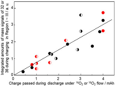
It is confirmed that all the O atoms in Li2O2 seemed to originate from the O2 gas flow during discharge by the results shown in Fig. 12, where integrated mass signals (ion currents) corresponding to O2 (Fig. 10(iii)) with 16O (red) or 18O (blue) contributions during charge with an LVS sweep of 0.05 mV s−1 for various cells are plotted as a function of charge passed during discharge under the corresponding isotope O2 gas flow. Black (●) and red ( ) closed circles are for the cells discharged under O2 gas of a single isotope i.e., 16O2 gas and 18O2 gas flow, respectively, throughout the discharge. Data of discharge time dependencies under 16O2 gas flow (Fig. 7 and 9) and 18O2 gas flow (Fig. 10) are included. Half-closed circles correspond to the cells discharged under two isotopes of O2 gas in sequence with the filled half for the order of gas flow. Thus, ◐ and
  are the integrated amounts of O2 based on 16O and 18O, respectively, during the charge for the cells with the initial 16O2 gas flow followed by 18O2 gas flow during discharge, and ◐ and
  are the integrated amounts of O2 based on 18O and 16O, respectively, during the charge for the cells with the initial 18O2 gas flow followed by 16O2 gas flow during discharge. Although the data are scattered, the amounts of O2 based on 16O and 18O are linearly related to the charge passed during discharge under 16O2 and 18O2 gas flow, respectively, regardless of the order of the gas flow. Thus, Li2O2 is formed with O2, which flowed at the time of Li2O2 formation.
The trends can be more clearly seen in Fig. 13 where the fraction of the 18O isotope, which was contained in the initial flow of O2 gas during discharge, and in O2 gas generated during charging is plotted as a function of cell voltage during LVS charging. In all the cases, the fraction was lowest at the beginning of the LVS charge and increased as the voltage increased up to ca. 4.5 V which corresponded to the 2nd current/O2 peak, confirming that the O isotope initially introduced during discharge was released in the later stage of charge. Behaviours in higher charge voltages were dependent on the order of isotope supply. When 18O2 was supplied initially during discharge, the fraction of the initially introduced O isotope (18O) reached a maximum at around 4.5 V and decreased at higher voltages (Fig. 13(a)–(c)). On the other hand, when 16O2 was supplied initially during discharge, the fraction of the initially introduced O isotope (16O) increased further when the voltage became larger than 4.5 V (Fig. 13(d)). These results show that the fraction of 16O increased more at voltages larger than ca. 4.5 V regardless of the order of the supply of two isotope O2 gases, suggesting that the source of O2 generated at larger voltages was not only Li2O2, which is the major discharge product and O source of which is O2 gas flowing during discharge, but also other molecules, which were formed during discharge and the O source of which includes TEGDME. One possible molecule is Li2CO3, which contains O from TEGDME as mentioned above and generates O2 accompanied with CO2 during charge as: Li2CO3 → 2Li+ + CO2 + 1/2O2 + 2e−.
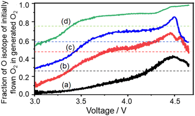 | ||
| Fig. 13 Fraction of the O isotope, which was contained in the initially flowing O2 gas during discharge, and in the O2 gas generated during LVS charge as a function of cell voltage. (a) 2.5 h 18O2 flow followed by 7.1 h 16O2 flow (black line: data taken from Fig. 10(b)), (b) 4 h 18O2 flow followed by 4.6 h 16O2 flow (red line: data taken from Fig. 10(c)), (c) 5.8 h 18O2 flow followed by 4.2 h 16O2 flow (blue line: data taken from Fig. 10(d)), and (d) 7.5 h 16O2 flow followed by 2.5 h 18O2 flow (green line: data taken from Fig. 10(e)). Dotted lines show the total fractions of the 18O isotope, which was contained in the initially flown O2 gas during discharge, for whole discharge processes. For example, the black dotted line shows 0.26 (= 2.5/(2.5 + 7.1)) for (a). | ||
4. Conclusions
In the present study, we monitored the generated gaseous products during charging under LVS and the voltage step of LOBs with 1 M LiTFSI TEGDME electrolyte solution in real time by using online mass spectrometry after the cell was discharged under constant current with a continuous flow of 16O2 or 18O2 gas and various discharge times. Based on the results obtained in the present study, we can conclude the following.(1) At least two types of Li2O2 are formed during discharge. While the Li2O2 grown in the later stage of discharge is oxidized in a wide range of relatively low cell voltages (l-Li2O2: 2.8 – ca. 4.1 V, depending on the discharge time), the Li2O2 grown in the earlier stage of discharge is oxidized in a relatively narrow range of high cell voltages (h-Li2O2) after the l-Li2O2 is oxidized. Thus, l-Li2O2 is energetically distributed very widely but the energetic states of h-Li2O2 are rather sharp, showing that l-Li2O2 is amorphous or crystalline with low crystallinity and h-Li2O2 is crystalline with high crystallinity as suggested before.73
(2) The current efficiency for the O2 generation by Li2O2 oxidation during LVS charge varied with voltage. It started to decrease as H2O generation started at around 3.36 V and decreased further as CO2 generation started at around 4.15 V. The total measured current can be well explained by considering partial currents due to O2 generation by Li2O2 oxidation, H2O generation, and CO2 generation up to ca. 4.66 V. In a higher voltage region, currents due to O2, H2O, and CO2 generation became small and those due to the decomposition of TEGDME and its degraded compounds increased significantly.
(3) The most plausible origin of H2O is the oxidation of LiOH, which is formed during discharge. Only about 50% of O in H2O generated during the charge comes from O2 gas flown during discharge. The remaining 50% O in H2O should originate from TEGDME, although there is a possibility that some fraction of O comes from residual H2O in the electrolyte solution.
(4) CO2 generation during LVS charge started not at a unique voltage but at a voltage, where O2 generation due to h-Li2O2 oxidation started, depending on the discharge time. Once h-Li2O2 oxidation was completed, almost no CO2 was generated even when higher voltages were applied, although the generation of organic molecules due to the degradation of the electrolyte, i.e., TEGDME, increased, showing CO2 generation during LVS charge is not due to the oxidation of TEGDME and/or its degraded compounds but due to the oxidation of Li2CO3, which is formed during discharge and is present at the same sites of the h-Li2O2. Only about 70% of O in CO2 generated during the charging comes from the O2 gas flow during discharge and the other fraction of O should originate from TEGDME.
More detailed discussion on the mechanisms of TEGDME degradation and its relationship to the generation of precursors of H2O and CO2, plausibly LiOH and Li2CO3, respectively, during discharge is underway.
Conflicts of interest
There are no conflicts to declare.Acknowledgements
YG is a NIMS Junior Research Fellow of the Center for Advanced Battery Collaboration supported by JST Grant (JPMJPF2016). KJCNT sheets were donated by KJCNT Specialty Paper. Characterizations of materials and cell assembly were carried out in a NIMS Battery Research Platform.Notes and references
- M. M. Thackeray, C. Wolverton and E. D. Isaacs, Energy Environ. Sci., 2012, 5, 7854–7863 RSC.
- K. Kanamura, Large-scale Batteries for Green Energy Society, in Electrochemical Science for a Sustainable Society, ed. K. Uosaki, Springer, 2017, pp. 175–195 Search PubMed.
- M. Fichtner, K. Edström, E. Ayerbe, M. Berecibar, A. Bhowmik, I. E. Castelli, S. Clark, R. Dominko, M. Erakca and A. A. Franco, Adv. Energy Mater., 2022, 12, 2102904 CrossRef CAS.
- M. Li, J. Lu, Z. Chen and K. Amine, Adv. Mater., 2018, 30, 1800561 CrossRef PubMed.
- P. G. Bruce, S. A. Freunberger, L. J. Hardwick and J.-M. Tarascon, Nat. Mater., 2012, 11, 19–29 CrossRef CAS PubMed.
- Principles and Applications of Lithium Secondary Batteries, ed. J.-K. Park, John Wiley & Sons, 2012, pp. 1–7 Search PubMed.
- M. Winter, B. Barnett and K. Xu, Chem. Rev., 2018, 118, 11433–11456 CrossRef CAS PubMed.
- P. Canepa, G. Sai Gautam, D. C. Hannah, R. Malik, M. Liu, K. G. Gallagher, K. A. Persson and G. Ceder, Chem. Rev., 2017, 117, 4287–4341 CrossRef CAS PubMed.
- T. Placke, R. Kloepsch, S. Dühnen and M. Winter, J. Solid State Electrochem., 2017, 21, 1939–1964 CrossRef CAS.
- M. Ue, K. Sakaushi and K. Uosaki, Mater. Horiz., 2020, 7, 1937–1954 RSC.
- N. Imanishi, A. C. Luntz and P. Bruce, The Lithium Air Battery: Fundamentals, Springer, 2014, pp. 1–21 Search PubMed.
- K. Abraham and Z. Jiang, J. Electrochem. Soc., 1996, 143, 1 CrossRef CAS.
- S. Matsuda, M. Ono, S. Yamaguchi and K. Uosaki, Mater. Horiz., 2022, 9, 856–863 RSC.
- N. B. Aetukuri, B. D. McCloskey, J. M. García, L. E. Krupp, V. Viswanathan and A. C. Luntz, Nat. Chem., 2015, 7, 50–56 CrossRef CAS PubMed.
- W.-J. Kwak, Rosy, D. Sharon, C. Xia, H. Kim, L. R. Johnson, P. G. Bruce, L. F. Nazar, Y.-K. Sun and A. A. Frimer, Chem. Rev., 2020, 120, 6626–6683 CrossRef CAS PubMed.
- Z. Wu, Y. Tian, H. Chen, L. Wang, S. Qian, T. Wu, S. Zhang and J. Lu, Chem. Soc. Rev., 2022, 51, 8045–8101 RSC.
- G. Girishkumar, B. McCloskey, A. C. Luntz, S. Swanson and W. Wilcke, J. Phys. Chem., 2010, 1, 2193–2203 CAS.
- J. P. Zheng, R. Y. Liang, M. Hendrickson and E. J. Plichta, J. Electrochem. Soc., 2008, 155, A432 CrossRef CAS.
- Z. Liang, W. Wang and Y.-C. Lu, Joule, 2022, 6, 2458–2473 CrossRef CAS.
- A. C. Luntz and B. D. McCloskey, Chem. Rev., 2014, 114, 11721–11750 CrossRef CAS PubMed.
- H.-G. Jung, J. Hassoun, J.-B. Park, Y.-K. Sun and B. Scrosati, Nat. Chem., 2012, 4, 579–585 CrossRef CAS PubMed.
- H. Woo, J. Kang, J. Kim, C. Kim, S. Nam and B. Park, Electron. Mater. Lett., 2016, 12, 551–567 CrossRef CAS.
- S. B. Ma, D. J. Lee, V. Roev, D. Im and S.-G. Doo, J. Power Sources, 2013, 244, 494–498 CrossRef CAS.
- D. Qu, AIP Conference Proceedings, Fundamental Principals of Battery Design: Porous Electrodes, USA, 2014, vol. 07 Search PubMed.
- J. Xiao, D. Mei, X. Li, W. Xu, D. Wang, G. L. Graff, W. D. Bennett, Z. Nie, L. V. Saraf and I. A. Aksay, Nano Lett., 2011, 11, 5071–5078 CrossRef CAS PubMed.
- L. Liu, Y. Liu, C. Wang, X. Peng, W. Fang, Y. Hou, J. Wang, J. Ye and Y. Wu, Small Methods, 2022, 6, 2101280 CrossRef CAS PubMed.
- F. Wang, X. Li, Y. Xie, Q. Lai and J. Tan, ACS Appl. Energy Mater., 2022, 5, 5473–5483 CrossRef CAS.
- C. Tran, X.-Q. Yang and D. Qu, J. Power Sources, 2010, 195, 2057–2063 CrossRef CAS.
- P. Albertus, T. Lohmann and J. Christensen, Overview of LiO2 Battery Systems with a Focus on Oxygen Handling Requirements and Technologies, in The Lithium Air Battery: Fundamentals, ed. N. Imanishi, A. C. Luntz and P. Bruce, Springer, 2014, pp. 306–308 Search PubMed.
- J.-H. Kang, J. Lee, J.-W. Jung, J. Park, T. Jang, H.-S. Kim, J.-S. Nam, H. Lim, K. R. Yoon, W.-H. Ryu, I.-D. Kim and H. R. Byon, ACS Nano, 2020, 14, 14549–14578 CrossRef CAS PubMed.
- D. Geng, N. Ding, T. S. A. Hor, S. W. Chien, Z. Liu, D. Wuu, X. Sun and Y. Zong, Adv. Energy Mater., 2016, 6, 1502164 CrossRef.
- N. Imanishi and O. Yamamoto, Mater. Today, 2014, 17, 24–30 CrossRef CAS.
- J.-G. Zhang, D. Wang, W. Xu, J. Xiao and R. E. Williford, J. Power Sources, 2010, 195, 4332–4337 CrossRef CAS.
- R. Black, B. Adams and L. Nazar, Adv. Energy Mater., 2012, 2, 801–815 CrossRef CAS.
- B. D. McCloskey, D. Bethune, R. Shelby, T. Mori, R. Scheffler, A. Speidel, M. Sherwood and A. Luntz, J. Phys. Chem., 2012, 3, 3043–3047 CAS.
- Y. Shao, F. Ding, J. Xiao, J. Zhang, W. Xu, S. Park, J. G. Zhang, Y. Wang and J. Liu, Adv. Funct. Mater., 2013, 23, 987–1004 CrossRef CAS.
- X. Yao, Q. Dong, Q. Cheng and D. Wang, Angew. Chem., Int. Ed., 2016, 55, 11344–11353 CrossRef CAS PubMed.
- C. O. Laoire, S. Mukerjee, K. Abraham, E. J. Plichta and M. A. Hendrickson, J. Phys. Chem. C, 2010, 114, 9178–9186 CrossRef CAS.
- T. Liu, J. P. Vivek, E. W. Zhao, J. Lei, N. Garcia-Araez and C. P. Grey, Chem. Rev., 2020, 120, 6558–6625 CrossRef CAS PubMed.
- M. Ue and K. Uosaki, Curr. Opin. Electrochem., 2019, 17, 106–113 CrossRef CAS.
- F. Li, T. Zhang and H. Zhou, Energy Environ. Sci., 2013, 6, 1125–1141 RSC.
- W. Xu, K. Xu, V. V. Viswanathan, S. A. Towne, J. S. Hardy, J. Xiao, Z. Nie, D. Hu, D. Wang and J.-G. Zhang, J. Power Sources, 2011, 196, 9631–9639 CrossRef CAS.
- Y.-C. Lu, B. M. Gallant, D. G. Kwabi, J. R. Harding, R. R. Mitchell, M. S. Whittingham and Y. Shao-Horn, Energy Environ. Sci., 2013, 6, 750–768 RSC.
- F. S. Gittleson, K. P. Yao, D. G. Kwabi, S. Y. Sayed, W. H. Ryu, Y. Shao-Horn and A. D. Taylor, ChemElectroChem, 2015, 2, 1446–1457 CrossRef CAS.
- K. Tomita, H. Noguchi and K. Uosaki, ACS Appl. Energy Mater., 2018, 1, 3434–3442 CrossRef CAS.
- C. Song, K. Ito, O. Sakata and Y. Kubo, RSC Adv., 2018, 8, 26293–26299 RSC.
- F. Marchini, S. Herrera, W. Torres, A. Y. Tesio, F. J. Williams and E. J. Calvo, Langmuir, 2015, 31, 9236–9245 CrossRef CAS PubMed.
- K. P. Yao, D. G. Kwabi, R. A. Quinlan, A. N. Mansour, A. Grimaud, Y.-L. Lee, Y.-C. Lu and Y. Shao-Horn, J. Electrochem. Soc., 2013, 160, A824 CrossRef CAS.
- B. D. McCloskey, D. S. Bethune, R. M. Shelby, G. Girishkumar and A. C. Luntz, J. Phys. Chem., 2011, 2, 1161–1166 CAS.
- M. Ue, H. Asahina, S. Matsuda and K. Uosaki, RSC Adv., 2020, 10, 42971–42982 RSC.
- B. D. McCloskey, R. Scheffler, A. Speidel, D. S. Bethune, R. M. Shelby and A. C. Luntz, J. Am. Chem. Soc., 2011, 133, 18038–18041 CrossRef CAS PubMed.
- T. Herl and F. M. Matysik, ChemElectroChem, 2020, 7, 2498–2512 CrossRef CAS.
- X. Xin, K. Ito and Y. Kubo, ACS Appl. Mater. Interfaces, 2017, 9, 25976–25984 CrossRef CAS PubMed.
- Y. Gao, H. Noguchi and K. Uosaki, RSC Adv., 2023, 13, 5467–5472 RSC.
- Y. Gao, H. Noguchi and K. Uosaki, ACS Energy Lett., 2023, 8, 1811–1817 CrossRef CAS.
- K. Tomita, H. Noguchi and K. Uosaki, J. Am. Chem. Soc., 2020, 142, 19502–19509 CrossRef CAS PubMed.
- K. Nishioka, M. Tanaka, H. Fujimoto, T. Amaya, S. Ogoshi, M. Tobisu and S. Nakanishi, Angew. Chem., Int. Ed., 2022, 61, e202112769 CrossRef CAS PubMed.
- Z. Zhang, X. Xiao, W. Yu, Z. Zhao and P. Tan, Nano Lett., 2022, 22, 7527–7534 CrossRef CAS PubMed.
- C. Tan, D. Cao, L. Zheng, Y. Shen, L. Chen and Y. Chen, J. Am. Chem. Soc., 2022, 144, 807–815 CrossRef CAS PubMed.
- Z. Zhao, J. Huang and Z. Peng, Angew. Chem., Int. Ed., 2018, 57, 3874–3886 CrossRef CAS PubMed.
- M. M. Ottakam Thotiyl, S. A. Freunberger, Z. Peng and P. G. Bruce, J. Am. Chem. Soc., 2013, 135, 494–500 CrossRef CAS PubMed.
- M. Balaish, J. W. Jung, I. D. Kim and Y. Ein-Eli, Adv. Funct. Mater., 2020, 30, 1808303 CrossRef CAS.
- B. D. McCloskey, A. Speidel, R. Scheffler, D. Miller, V. Viswanathan, J. Hummelshøj, J. Nørskov and A. Luntz, J. Phys. Chem., 2012, 3, 997–1001 CAS.
- Y. Chen, S. A. Freunberger, Z. Peng, F. Bardé and P. G. Bruce, J. Am. Chem. Soc., 2012, 134, 7952–7957 CrossRef CAS PubMed.
- S. A. Freunberger, Y. Chen, N. E. Drewett, L. J. Hardwick, F. Bardé and P. G. Bruce, Angew. Chem., Int. Ed., 2011, 50, 8609–8613 CrossRef CAS PubMed.
- S. Meini, N. Tsiouvaras, K. U. Schwenke, M. Piana, H. Beyer, L. Lange and H. A. Gasteiger, Phys. Chem. Chem. Phys., 2013, 15, 11478–11493 RSC.
- D. Zhu, L. Zhang, M. Song, X. Wang, R. Mi, H. Liu, J. Mei, L. W. Lau and Y. Chen, J. Solid State Electrochem., 2013, 17, 2539–2544 CrossRef CAS.
- D. Oh, K. Virwani, L. Tadesse, M. Jurich, N. Aetukuri, L. E. Thompson, H.-C. Kim and D. S. Bethune, J. Phys. Chem. C, 2017, 121, 1404–1411 CrossRef CAS.
- Z. Peng, S. A. Freunberger, Y. Chen and P. G. Bruce, Science, 2012, 337, 563–566 CrossRef CAS PubMed.
- K. Nishioka, K. Morimoto, T. Kusumoto, T. Harada, K. Kamiya, Y. Mukouyama and S. Nakanishi, J. Am. Chem. Soc., 2021, 143, 7394–7401 CrossRef CAS PubMed.
- Y. Wang and Y. C. Lu, Angew. Chem., 2019, 131, 7036–7040 CrossRef.
- J. Wang, Y. Zhang, L. Guo, E. Wang and Z. Peng, Angew. Chem., Int. Ed., 2016, 55, 5201–5205 CrossRef CAS PubMed.
- S. Ganapathy, B. D. Adams, G. Stenou, M. S. Anastasaki, K. Goubitz, X.-F. Miao, L. F. Nazar and M. Wagemaker, J. Am. Chem. Soc., 2014, 136, 16335–16344 CrossRef CAS PubMed.
- S. E. Renfrew and B. D. McCloskey, J. Am. Chem. Soc., 2017, 139, 17853–17860 CrossRef CAS PubMed.
| This journal is © the Owner Societies 2024 |

