Facile synthesis strategy for cesium tin halide perovskite crystals toward light emitting devices and anti-counterfeiting flexible fiber†
Ziyao
Hu
a,
Kun
Nie
 *ab,
Xuyi
Wang
*c,
Xiuqiang
Duan
a,
Ranran
Zhou
a,
Mengyun
Wu
a,
Xiaoxue
Ma
*a,
Xiaodong
Zhang
a,
Luoxin
Wang
a,
Lefu
Mei
d and
Hua
Wang
a
aHubei Key Laboratory for New Textile Materials and Applications and State Key Laboratory of New Textile Materials & Advanced Processing Technology, School of Materials Science and Engineering, Wuhan Textile University, Wuhan 430200, P. R. China. E-mail: knie@wtu.edu.cn; xxma@wtu.edu.cn
bKey Laboratory of Testing and Tracing of Rare Earth Products for State Market Regulation, Jiangxi University of Science and Technology, Ganzhou 341000, P. R. China
cChina Bluestar Chengrand Co., Ltd, High Tech Organic Fiber Key Laboratory of Sichuan Province, Chengdu 610042, P. R. China. E-mail: xuyiwang2015@163.com
dBeijing Key Laboratory of Materials Utilization of Nonmetallic Minerals and Solid Wastes, National Laboratory of Mineral Materials, School of Materials Science and Technology, China University of Geosciences (Beijing), Beijing 100083, P. R. China
First published on 6th February 2023
Abstract
All-inorganic metal halide perovskites are widely studied because of their excellent photoelectric properties. However, due to the toxicity of CsPbX3 (X = Cl, Br, I) perovskites, it is difficult to apply them on a large scale. The lead-free nature and air stability make Cs2SnX6 (X = Cl, Br, I) perovskites possible candidates to replace CsPbX3 perovskites. Herein, we report the perovskite crystals (PCs) based on Te(IV)-doped Cs2SnCl6: Cs2Sn1−xTexCl6. Cs2Sn1−xTexCl6 PCs showed yellow emission under a 365 nm ultraviolet lamp. The photoluminescence quantum yield (PLQY) of Cs2Sn0.94Te0.06Cl6 PCs was 57.09%, which was proposed to be from the triplet Te(IV) ion 3P1 → 1S0 self-trapping excitons (STE) recombination. The perovskite crystals can be used to fabricate light-emitting diodes (LEDs). The fiber paper prepared from aramid chopped fibers (ACFs) and polyphenylene sulfide (PPS) fibers showed a bright yellow light under 365 nm ultraviolet light after being post-processed with Cs2Sn1−xTexCl6 PCs solution. The ACFs/PPS compound fiber paper modified with Cs2Sn1−xTexCl6 PCs maintained exceptional optical properties and could be stored in air for more than 4500 h. The fluorescence performance of the modified ACFs/PPS compound fiber paper could be applied to fluorescence anti-counterfeiting. The modification strategy and the applications in this work will provide a good choice for studying the optical performance of perovskites and broaden the application of ACFs/PPS compound fiber paper.
Introduction
Lead halide CsPbX3 (X = Cl, Br, I) perovskites are widely applied in optoelectronics because of their excellent optical performance.1–3 For example, perovskites are widely used in photoelectric detection, solar cells, and other fields.4–6 Perovskites are modified to improve their photoelectric conversion efficiency (PCE) and obtain the desired emission wavelength.7–10 At the same time, the performance of perovskites can be improved by changing the morphologies of the perovskites.11 The team of Miyasaka reported first metal halide perovskites solar cells with a PCE of 3.8%.12 The PCE of perovskites solar cells is still rising.13–15 However, the toxicity, and instability of lead-based perovskites make it difficult to use them in commercial applications.16–18 The low toxicity and air stability of the element Sn(IV) make it possible for Cs2SnX6 (X = Cl, Br, I) to replace CsPbX3.19,20 However, although Cs2SnCl6 has a direct band gap, it hardly emits light under ultraviolet light. Therefore, synthesizing Cs2SnCl6 doped with other metal elements is of great significance to enhance its optical properties.Doping refers to introducing impurities into intrinsic semiconductors to change their electrical properties.21 Existing studies have shown that doping has an important effect on improving the optical performance of perovskites.22 For instance, doping lanthanide into perovskite nanocrystals can greatly improve and expand the optical properties.23 Sb-doped Cs2SnCl6 shows a photoluminescence peak at 630 nm with orange-red emission, and Bi-doped Cs2SnCl6 can yield blue self-trapping excitons (STE) emission. However, the unequal valence states between Bi3+ and Sn4+ make a large number of anion sublattices easily appear in the double-doped Cs2SnCl6, which may reduce the photoluminescence quantum yield (PLQY).24 According to this view, tetravalent ion doping can significantly reduce the formation of extrinsic defects and promote optical properties. A lead-free perovskite Cs2Sn1−xTexCl6 can show a bright yellow light under the irradiation of 365 nm ultraviolet light and has high anti-water stability.25 A Te4+-doped Cs2SnCl6 vacancy-ordered perovskite variant shows green-yellow emission.26 However, the previous synthesis methods required some special ligands or Teflon liners. Therefore, it is urgent to synthesize Cs2Sn1−xTexCl6 using a more economical and convenient method. In this paper, Cs2Sn1−xTexCl6 perovskite crystals (PCs) with different doping ratios were synthesized via a more convenient hydrothermal method. A light-emitting diode (LED) lamp was fabricated by combining a 385 nm chip and Cs2Sn0.94Te0.06Cl6 PCs. The LED lamp could emit yellow light driven by a 600 mA current. Furthermore, we have modified fiber paper prepared from aramid chopped fibers (ACFs) and polyphenylene sulfide (PPS) fiber by post-processing it with the Cs2Sn1−xTexCl6 PCs solution. The modified ACFs/PPS compound fiber paper showed a bright yellow light under 365 nm ultraviolet light. The modified fiber paper could maintain exceptional optical properties even when soaked in a weak acid solution (pH = 5). The optical properties of the modified ACFs/PPS compound fiber paper can be applied in fluorescence anti-counterfeiting. The modification strategy and the application in this paper will provide a good choice for studying the optical properties of perovskites and broaden the application of ACFs/PPS compound fiber paper.
Results and discussion
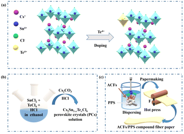
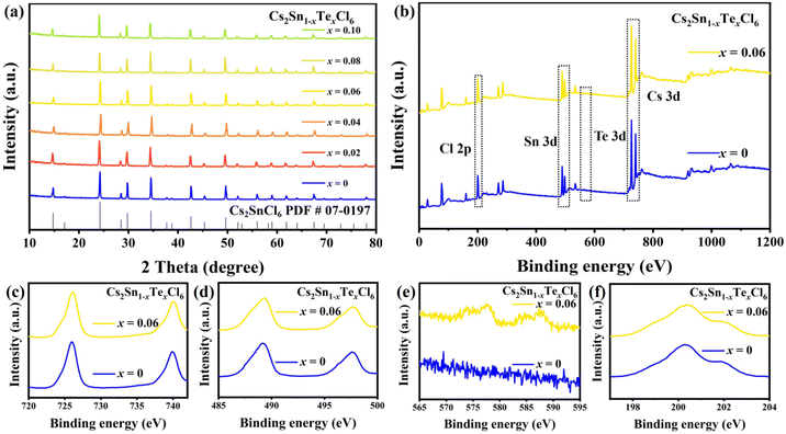
Cs2Sn1−xTexCl6 PCs with different doping ratios were synthesized via a more convenient hydrothermal method (shown in Fig. 1b). The ACFs/PPS compound fiber paper was prepared via a wet papermaking method (shown in Fig. 1c). The left part of Fig. 1a shows the crystal structure of Cs2SnCl6. Tetravalent tin(IV) ions usually occupy the central site and form the standalone [SnCl6]2− octahedral structure. The crystal structure of Cs2Sn1−xTexCl6 is shown in the right part of Fig. 1a. The [TeCl6]2− replaced part of the [SnCl6]2− by doping with tetravalent Te(IV). The X-ray diffraction (XRD) patterns and photoluminescence (PL) spectra of Cs2Sn0.94Te0.06Cl6 with different reaction times are shown in Fig. S1 and S2.† The PL intensity of the Cs2Sn0.94Te0.06Cl6 PCs obtained after 60 minutes of reaction is the highest. The XRD pattern of un-doped Cs2SnCl6 matches well with the standard card (no.: 07-0197) (Fig. 2a). There were no impurity diffraction peaks observed after doping Te4+ into Cs2SnCl6 because of the similar coordination property to halogen of elements Te and Sn,26 which proved that the synthesized Cs2Sn1−xTexCl6 perovskite crystals were of high purity. At the same time, the optical properties (shown in Fig. 4(a)) of the doped perovskite crystals have been significantly improved. It can be reasonably inferred that part of [TeCl6]2− replaces [SnCl6]2− in the structure. The X-ray photoelectron spectroscopy XPS spectra (Fig. 2b) showed the specific elements’ content of Cs2SnCl6 and Cs2Sn0.94Te0.06Cl6. The detailed XPS spectra (Fig. 2c, d, and f) of Cs, Sn, and Cl of Cs2Sn0.94Te0.06Cl6 were practically consistent with Cs2SnCl6. In contrast, the XPS spectrum of Te of Cs2Sn0.94Te0.06Cl6 was different from that of Cs2SnCl6, which proved that Te had been doped into Cs2SnCl6 successfully. The atomic ratio of Cs, Sn, and Cl in un-doped Cs2SnCl6 was close to 2![[thin space (1/6-em)]](https://www.rsc.org/images/entities/char_2009.gif) :
:![[thin space (1/6-em)]](https://www.rsc.org/images/entities/char_2009.gif) 1
1![[thin space (1/6-em)]](https://www.rsc.org/images/entities/char_2009.gif) :
:![[thin space (1/6-em)]](https://www.rsc.org/images/entities/char_2009.gif) 6. The atomic ratio of Te in Cs2Sn1−xTexCl6 increased with the doping concentration increasing (shown in Table S1†). The scanning electron microscope (SEM) image of un-doped Cs2SnCl6 is shown in Fig. 3a. The elemental mapping images of Cs, Sn, Te, and Cl in Cs2Sn0.94Te0.06Cl6 are shown in Fig. 3b–f. The SEM image of Cs2Sn0.94Te0.06Cl6 is shown in Fig. 3g. It can be observed that the crystal morphology of Cs2Sn1−xTexCl6 after modification is almost unchanged.
6. The atomic ratio of Te in Cs2Sn1−xTexCl6 increased with the doping concentration increasing (shown in Table S1†). The scanning electron microscope (SEM) image of un-doped Cs2SnCl6 is shown in Fig. 3a. The elemental mapping images of Cs, Sn, Te, and Cl in Cs2Sn0.94Te0.06Cl6 are shown in Fig. 3b–f. The SEM image of Cs2Sn0.94Te0.06Cl6 is shown in Fig. 3g. It can be observed that the crystal morphology of Cs2Sn1−xTexCl6 after modification is almost unchanged.
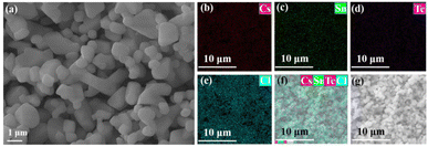 | ||
| Fig. 3 (a) SEM image of Cs2SnCl6. (b–f) Elemental mapping images of Cs, Sn, Te, Cl in Cs2Sn0.94Te0.06Cl6. (g) SEM image of Cs2Sn0.94Te0.06Cl6. | ||
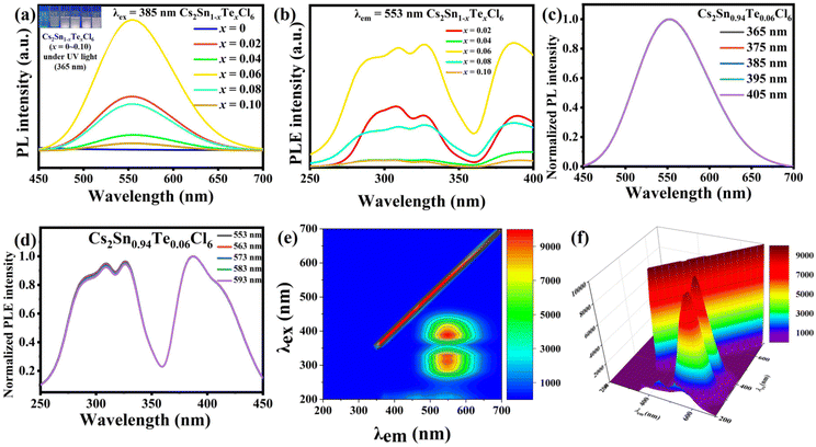
The PL and photoluminescence excitation (PLE) spectra of Cs2Sn1−xTexCl6 PCs are shown in Fig. 4a and b. The un-doped Cs2SnCl6 was hardly luminous, while the PL intensities of Cs2Sn1−xTexCl6 were significantly enhanced. It could be observed that the PL intensity of Cs2Sn1−xTexCl6 was the highest when x = 0.06 and then decreased with the increase in Te4+ doping. According to previous reports, this reduction in PL was attributed to the concentration quenching process where the excitation energy migrated to the quenching sites through the lattice.27 They calculated the critical distance (R) for [TeCl6]2−–[TeCl6]2− energy transfer. According to the formula R6 = (0.6 × 1028)(4.8 × 10⁻¹⁶f/E4)SO, the calculated R is almost three times the shortest Te–Te distance, which means that there is the possibility of energy transfer. f is the oscillator strength of the relevant 1S0→3P1 transition and is taken to be 10−2; E, the energy of maximum spectral overlap, is 2.5 eV; SO, the spectral overlap of emission and absorption, amounts to 0.1 eV−1. The peak position of the PL intensity showed a slight red shift with the increase in the amount of Te4+ doped. For halide perovskites with a soft lattice, the photogenerated electrons at the excited state levels tend to be coupled with lattice vibration, causing transient lattice distortion, changing nuclear coordinates, and producing local STE.28 Tetravalent Te, as a typical ion with the outer electronic configuration of 5s2, has five energy levels: ground state of 1S0 and singlet/triplet excited states of 1P1/3Pn (n = 0, 1, 2).29 Self-trapping excitons widely exist in perovskites.30 In some perovskite crystals, the electrons and holes generated by excitation will immediately be self-trapped because the self-trapped state is more stable. According to other reports, both a broad PL band and large Stokes shift are typical features of STE emission.31,32 Take Cs2Sn0.94Te0.06Cl6 for example, the PL band starts at 450 nm and ends at 700 nm. The excitation wavelength is 385 nm, and the emission wavelength is 553 nm. Based on these data, it can be reasonably inferred that the fluorescence property of Te-doped Cs2SnCl6 is due to STE emission. Fig. 4c and d are the PL and PLE spectra of Cs2Sn0.94Te0.06Cl6 PCs. It can be observed that the PL and PLE spectra almost maintain the same wave profile no matter how the excitation and emission change, which proves that the emission band is the luminescence characteristic of Cs2Sn0.94Te0.06Cl6 PCs, not the surface defects or the lattice defects of the samples. The test results verify the STE and ion luminescence characteristics of Cs2Sn1−xTexCl6. Fig. 4e and f are the two-dimensional (2D) and three-dimensional (3D) fluorescence spectra of Cs2Sn0.94Te0.06Cl6 PCs. It can be observed that the emission wavelength varies between 500 nm to 600 nm, while the excitation wavelength varies between 250 nm to 450 nm. The time-resolved (TRPL) decay curves (shown in Fig. 5a) of Cs2Sn1−xTexCl6 PCs can be well fitted with the bi-exponential eqn (1):33
I(t) = A1![[thin space (1/6-em)]](https://www.rsc.org/images/entities/char_2009.gif) exp(−t/τ1) + A2 exp(−t/τ1) + A2![[thin space (1/6-em)]](https://www.rsc.org/images/entities/char_2009.gif) exp(−t/τ2). exp(−t/τ2). | (1) |
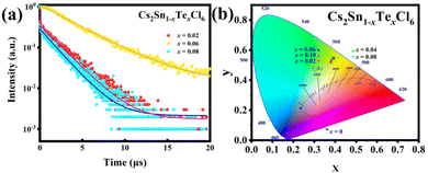 | ||
| Fig. 5 (a) TRPL decay curves of Cs2Sn1−xTexCl6 (x = 0.02, 0.06, 0.08) PCs. (b) Chromaticity coordinates (CIE 1931) of Cs2Sn1−xTexCl6 (x = 0.02, 0.04, 0.06, 0.08, 0.10) PCs. | ||
The average fluorescence lifetime can be calculated using eqn (2):21
| τavg = (A1τ12 + A2τ22)/(A1τ1 + A2τ2). | (2) |
It can be calculated that the average fluorescence lifetimes of Cs2Sn1−xTexCl6 PCs are 2.06 μs (x = 0.02), 38.61 μs (x = 0.06) and 1.83 μs (x = 0.08). At the same time, combined with the PL spectra (Fig. 4(a)), the emission intensity of the sample is positively related to its lifetime. The chromaticity coordinate (CIE) values of un-doped Cs2SnCl6 PCs and Cs2Sn1−xTexCl6 can be calculated to be (0.23, 0.21), (0.38, 0.52), (0.39, 0.54), (0.39, 0.55), (0.39, 0.54), (0.38, 0.53), which appeared in the yellow area of the CIE (Fig. 5b). The color purity of Cs2Sn1−xTexCl6 PCs can be calculated from eqn (3):34
 | (3) |
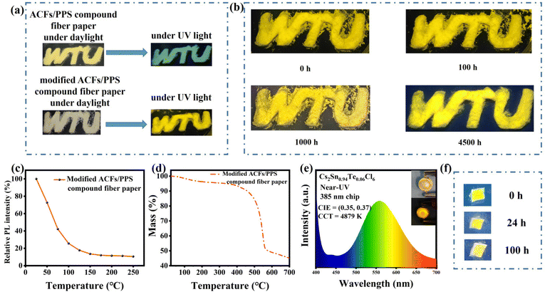
Meanwhile, we modified the ACFs/PPS compound fiber paper by post-processing it with Cs2Sn0.94Te0.06Cl6 PCs solution. Fig. 6a shows that the modified ACFs/PPS compound fiber paper showed bright yellow light under UV light while the unmodified paper did not. Although stored in air for more than 4500 h, the modified fiber paper still showed a bright yellow light (Fig. 6b). Furthermore, the modified paper can still maintain luminescence characteristics when it was immersed in a weak acid solution (Fig. 6f). The PLQY of the modified fiber paper soaked in a weak acid solution was 17.63%. It could be observed that the fluorescence intensities of the modified fiber paper decreased with the increase in temperature (Fig. 6c). It was similar to the reduction in PL intensity due to the participation of phonons in nonradiative recombination at high temperatures. The thermal stability of the modified ACFs/PPS compound fiber paper can be verified by the thermogravimetric analysis (Fig. 6d). PL spectra of the ACFs/PPS composite fiber paper were measured at 50 °C and after falling back from 250 °C (shown in Fig. S4(a)†). The modified composite fiber paper could retain 82% of the original emission intensity when it fell from 250 to 50 °C. In addition, PL intensities of the ACFs/PPS composite fiber paper were measured at different temperatures. The intensity of PL decreased gradually with increasing temperature (shown in Fig. S4(b)†). However, after heating for 5 min, an enhancement in the PL intensity at some temperatures can be seen. Furthermore, the average intensity of PL can still maintain 98% of the original PL intensity when it falls from 100 to 40 °C. It can be observed that the sublimation temperature of the modified ACFs/PPS compound fiber paper is about 300 °C (Fig. 6c). Based on the above data, it can be concluded that the ACFs/PPS composite fiber paper has a certain degree of thermal stability. These test results have laid a good foundation for use of the modified ACFs/PPS compound fiber paper as a fluorescent anti-counterfeiting material.
Conclusions
To sum up, the Cs2Sn1−xTexCl6 PCs were synthesized via a more convenient hydrothermal method. The synthesized perovskite crystals showed obvious fluorescence and the emission center was 553 nm. Cs2Sn0.94Te0.06Cl6 PCs showed the highest fluorescence intensity, where the PLQY could reach 57.09%. Through the PL and PLE spectra, it could be inferred that the fluorescence of Cs2Sn1−xTexCl6 PCs was attributed to the doping of the Te element. The LED lamp fabricated by combining a 385 nm n-UV chip and Cs2Sn0.94Te0.06Cl6 PCs could emit yellow light driven by the current. Furthermore, ACFs/PPS compound fiber paper was post-processed with Cs2Sn1−xTexCl6 PCs solution. The test results in this paper showed that the modified ACFs/PPS compound fiber paper can maintain fluorescence properties in air and a weak acid environment for a long time, which laid a good foundation for it as a fluorescent anti-counterfeiting material. This work provides a good choice to study the optical performance of perovskites crystals and broadens the application of the ACFs/PPS compound fiber paper.Author contributions
Ziyao Hu: conceptualization, investigation, methodology, data curation, formal analysis, writing – original draft; Kun Nie: resources, conceptualization, supervision, project administration, funding acquisition, writing – review and editing; Xuyi Wang: project administration, funding acquisition; Xiuqiang Duan: investigation, methodology; Ranran Zhou: investigation, methodology; Mengyun Wu: investigation; Xiaoxue Ma: resources; Xiaodong Zhang: investigation; Luoxin Wang: project administration, funding acquisition; Lefu Mei: funding acquisition, project administration; Hua Wang: funding acquisition, project administration.Conflicts of interest
There are no conflicts to declare.Acknowledgements
This work was supported by the Key Laboratory of Testing and Tracing of Rare Earth Products for State Market Regulation (Jiangxi University of Science and Technology) (TTREP2022YB04), the National Natural Science Foundation of China (51872269, 52274273), the Science and Technology Research Project of Hubei Provincial Department of Education (B2021091), Key Laboratory for New Textile Materials and Applications of Hubei Province (Wuhan Textile University) (FZXCL202107), the Open Project Program of High-Tech Organic Fibers Key Laboratory of Sichuan Province, and China and National Project Cultivation Plan of Wuhan Textile University. This work was supported by the Graduate Innovation Fund Project of Wuhan Textile University. The authors would like to thank Liu Nian and Liu Tianying from Shiyanjia Lab (https://www.shiyanjia.com) for the XPS and SEM characterizations.Notes and references
- L. Protesescu, S. Yakunin, M. I. Bodnarchuk, F. Krieg, R. Caputo, C. H. Hendon, R. X. Yang, A. Walsh and M. V. Kovalenko, Nano Lett., 2015, 15, 3692–3696 CrossRef CAS PubMed.
- G. Nedelcu, L. Protesescu, S. Yakunin, M. I. Bodnarchuk, M. J. Grotevent and M. V. Kovalenko, Nano Lett., 2015, 15, 5635–5640 CrossRef CAS PubMed.
- J. Song, J. Li, X. Li, L. Xu, Y. Dong and H. Zeng, Adv. Mater., 2015, 27, 7162–7167 CrossRef CAS PubMed.
- J. Deng, J. Li, Z. Yang and M. Wang, J. Mater. Chem. C, 2019, 7, 12415–12440 RSC.
- F. Wang, M. Endo, S. Mouri, Y. Miyauchi, Y. Ohno, A. Wakamiya, Y. Murata and K. Matsuda, Nanoscale, 2016, 8, 11882–11888 RSC.
- L. Y. Wang, L. L. Deng, X. Wang, T. Wang, H. R. Liu, S. M. Dai, Z. Xing, S. Y. Xie, R. B. Huang and L. S. Zheng, Nanoscale, 2017, 9, 17893–17901 RSC.
- K. A. Bush, A. F. Palmstrom, Z. J. Yu, M. Boccard, R. Cheacharoen, J. P. Mailoa, D. P. McMeekin, R. L. Z. Hoye, C. D. Bailie, T. Leijtens, I. M. Peters, M. C. Minichetti, N. Rolston, R. Prasanna, S. Sofia, D. Harwood, W. Ma, F. Moghadam, H. J. Snaith, T. Buonassisi, Z. C. Holman, S. F. Bent and M. D. McGehee, Nat. Energy, 2017, 2, 17009 CrossRef CAS.
- M. Jiang, J. Yuan, G. Cao and J. Tian, Chem. Eng. J., 2020, 402, 126152 CrossRef CAS.
- M. I. Kholil and M. T. Hossen Bhuiyan, RSC Adv., 2020, 10, 43660–43669 RSC.
- Y.-H. Song, J. S. Yoo, E. K. Ji, C. W. Lee, G. S. Han, H. S. Jung and D.-H. Yoon, Chem. Eng. J., 2016, 306, 791–795 CrossRef CAS.
- R. Zhou, C. A. Cheng, S. Qiu, J. Chen, K. Nie, M. Wu, P. Lin, H. Wang, L. Wang and L. Mei, RSC Adv., 2021, 11, 28716–28722 RSC.
- A. Kojima, K. Teshima, Y. Shirai and T. Miyasaka, J. Am. Chem. Soc., 2009, 131, 6050–6051 CrossRef CAS PubMed.
- S. S. Mali, C. S. Shim, H. Kim, P. S. Patil and C. K. Hong, Nanoscale, 2016, 8, 2664–2677 RSC.
- Y. Liu, W. Xiang, S. Mou, H. Zhang and S. Liu, Chem. Eng. J., 2022, 447, 137515 CrossRef CAS.
- N.-G. Park, Mater. Today, 2015, 18, 65–72 CrossRef CAS.
- A. Babayigit, A. Ethirajan, M. Muller and B. Conings, Nat. Mater., 2016, 15, 247–251 CrossRef CAS PubMed.
- W. Ke and M. G. Kanatzidis, Nat. Commun., 2019, 10, 965 CrossRef PubMed.
- A. H. Slavney, R. W. Smaha, I. C. Smith, A. Jaffe, D. Umeyama and H. I. Karunadasa, Inorg. Chem., 2017, 56, 46–55 CrossRef CAS PubMed.
- T. C. Jellicoe, J. M. Richter, H. F. Glass, M. Tabachnyk, R. Brady, S. E. Dutton, A. Rao, R. H. Friend, D. Credgington, N. C. Greenham and M. L. Bohm, J. Am. Chem. Soc., 2016, 138, 2941–2944 CrossRef CAS PubMed.
- X. Qiu, B. Cao, S. Yuan, X. Chen, Z. Qiu, Y. Jiang, Q. Ye, H. Wang, H. Zeng, J. Liu and M. G. Kanatzidis, Sol. Energy Mater. Sol. Cells, 2017, 159, 227–234 CrossRef CAS.
- J. Jiang, Q. Wang, Z. Jin, X. Zhang, J. Lei, H. Bin, Z.-G. Zhang, Y. Li and S. F. Liu, Adv. Energy Mater., 2018, 8, 1701757 CrossRef.
- W. J. Mir, Y. Mahor, A. Lohar, M. Jagadeeswararao, S. Das, S. Mahamuni and A. Nag, Chem. Mater., 2018, 30, 8170–8178 CrossRef CAS.
- G. Pan, X. Bai, D. Yang, X. Chen, P. Jing, S. Qu, L. Zhang, D. Zhou, J. Zhu, W. Xu, B. Dong and H. Song, Nano Lett., 2017, 17, 8005–8011 CrossRef CAS PubMed.
- A. Yan, K. Li, Y. Zhou, Y. Ye, X. Zhao and C. Liu, J. Alloys Compd., 2020, 822, 153528 CrossRef CAS.
- Z. Tan, Y. Chu, J. Chen, J. Li, G. Ji, G. Niu, L. Gao, Z. Xiao and J. Tang, Adv. Mater., 2020, 32, 2002443 CrossRef CAS PubMed.
- R. Zeng, K. Bai, Q. Wei, T. Chang, J. Yan, B. Ke, J. Huang, L. Wang, W. Zhou, S. Cao, J. Zhao and B. Zou, Nano Res., 2021, 14, 1551–1558 CrossRef CAS.
- G. Blasse, G. J. Dirksen and W. Abriel, Chem. Phys. Lett., 1987, 136, 460–464 CrossRef CAS.
- B. Ke, R. Zeng, Z. Zhao, Q. Wei, X. Xue, K. Bai, C. Cai, W. Zhou, Z. Xia and B. Zou, J. Phys. Chem. Lett., 2020, 11, 340–348 CrossRef CAS PubMed.
- T. V. Sedakova and A. G. Mirochnik, Opt. Spectrosc., 2016, 120, 268–273 CrossRef CAS.
- S. You, T. Zhu, Y. Wang, Z. K. Zhu, Z. Li, J. Wu, P. Yu, L. Li, C. Ji, Y. Wang, S. Wang and J. Luo, Adv. Funct. Mater., 2022, 2210481 CrossRef.
- B. M. Benin, D. N. Dirin, V. Morad, M. Worle, S. Yakunin, G. Raino, O. Nazarenko, M. Fischer, I. Infante and M. V. Kovalenko, Angew. Chem., Int. Ed., 2018, 57, 11329–11333 CrossRef CAS PubMed.
- V. Morad, Y. Shynkarenko, S. Yakunin, A. Brumberg, R. D. Schaller and M. V. Kovalenko, J. Am. Chem. Soc., 2019, 141, 9764–9768 CrossRef CAS PubMed.
- R. Zhou, C. A. Cheng, X. Wang, K. Nie, J. Wu, M. Wu, X. Duan, Z. Hu, I. U. Huq, H. Wang, L. Wang, L. Mei, H. Liu and X. Ma, Nano Res., 2023, 16, 3542–3551 Search PubMed.
- K. Nie, X. Ma, P. Lin, N. Kumar, L. Wang and L. Mei, J. Rare Earths, 2021, 39, 1320–1326 CrossRef CAS.
Footnote |
| † Electronic supplementary information (ESI) available. See DOI: https://doi.org/10.1039/d3nr00301a |
| This journal is © The Royal Society of Chemistry 2023 |

