Functionalized polymer modified buried interface for enhanced efficiency and stability of perovskite solar cells†
Hanjun
Zou
a,
Huan
Bi
 *b,
Yongheng
Chen
c,
Mengna
Guo
d,
Wenjing
Hou
d,
Pengyu
Su
e,
Kai
Zhou
a,
Chuanyao
Yang
a,
Xiangnan
Gong
a,
Li
Xiao
f and
Li
Liu
*c
aAnalytical and Testing Center, Chongqing University, Chongqing 401331, China
bFaculty of Informatics and Engineering, The University of Electro-Communications, Tokyo 182-8585, Japan. E-mail: hbi.trans.sci@uec.ac.jp
cJoint Laboratory for Extreme Conditions Matter Properties, School of Mathematics and Physics, Southwest University of Science and Technology, Mianyang 621010, China. E-mail: liuli_phy@swust.edu.cn
dInstitute of Molecular Science, Key Laboratory of Materials for Energy Conversion and Storage of Shanxi Province, Shanxi University, Taiyuan 030006, China
eSchool of Electronic Information Engineering, Yangtze Normal University, Chongqing 408100, China
fChongqing Key Laboratory of Green Energy Materials Technology and Systems, Chongqing University of Technology, Chongqing 400054, China
First published on 22nd December 2022
Abstract
Although great progress has been made in perovskite solar cells (PCSs), further development of PCSs is hindered by a large number of defects, nonradiative recombination, and mysterious stresses. Here, we propose a new interfacial strategy by introducing a new polymer material named povidone-iodine (PV-I) as a buffer layer. A series of studies indicate that the introduced buffer layer can form a strong chemical interaction with SnO2 and the perovskite, which can not only passivate the defects of the two functional layers but also strengthen the interfacial connection. The reduction of film defects and the enhancement of interface connection are beneficial to the extraction and transport of the carrier. In addition, the introduction of a buffer layer releases the interfacial stress. Ultimately, we achieved attractive efficiency (22.02%, 0.1 cm2) and considerable long-term stability (after aging 500 h, the target device still retains 81% of its original PCE). The excellent performance of the device indicates that this strategy can be used as an effective control method for perovskite solar cells to facilitate their commercialization.
Introduction
Organic–inorganic perovskite solar cells (PSCs) have made great process since first reported by Miyasaka.1 Until now, single junction PSCs have achieved a power conversion efficiency (PCE) of 25.7%,2 and thus PSCs are considered the mainstay of the next-generation photovoltaic market. However, there is still some distance with the limit of the PCE of PSCs due to defect-abundance and severe interfacial nonradiative recombination.3–5 So, it is important for PSCs to passivate defects and improve the interface contact.It has been reported that film quality and interface features are the key factors affecting device efficiency.6,7 To date, many strategies have been proposed to improve film quality, such as additive strategies, interface engineering, anti-solvent engineering, preparation process improvement, etc.7–10 Among these, interface engineering, especially buffer layer interface engineering, has been considered an effective method because it cannot only improve the quality of the perovskite film but is also expected to enhance the interface contact. Zhang and coworkers used hydroxyethyl piperazine ethane sulfonic acid (HEPES) as a buffer layer to modify the interface between SnO2 and perovskite.11 The result shows that the buffer layer can not only improve the crystallinity of the perovskite film and reduce the interface defects but also adjust the interfacial energy level. Finally, the PCE of PSCs increased from 18.43% to 20.22%. Our previous work also proved that interface engineering is important for PSCs.12,13 Therefore, it is necessary to develop new molecules for buried bottom interfaces to improve device efficiency.
On the other hand, due to the lattice mismatch of the fabrication process and the interface, there is a large amount of residual stress at the interface and the thin film of the device. These residual stresses can accelerate device failure as water and oxygen are more likely to attack where residual stresses exist.14–17 Therefore, it is urgent to find new strategies to improve stress distribution in devices. Zhang et al. attempted to release the interface stress by introducing a protonated amine silane coupling agent (PASCA-Br) between TiO2 and perovskite layers.18 Significant stress relief was observed due to the presence of PASCA-Br. The final performance of the device was greatly improved due to the disappearance of stress. We also tried to introduce ionic liquids to improve interfacial contact and release interfacial stress, thus achieving attractive efficiency.9,19 To sum up, how to release the residual stress is very important to improve the efficiency and stability of the device.
So far, many works have demonstrated that polymers have excellent performance in terms of improving device performance and stability.20–23 For example, Chen et al. showed that through an in situ cross-linking method, an ultra-thin polymer passivation layer was formed on the surface of the perovskite film, and a 1D perovskite layer was formed at the same time. This passivation strategy not only improves the carrier transport performance of the interface. At the same time, the interface defect density is reduced, and the residual tensile stress is released. Finally, the device shows an excellent PCE excess of 21%.24 Polymethyl methacrylate (PMMA) was used as a template to control the nucleation and growth process of perovskite thin films by Grätzel et al.25 The experimental results prove that the films grown by the template method are shiny and smooth and have an ultra-long photoluminescence lifetime. At the same time, the defects of the perovskite film are reduced. Ultimately, the device performance was as high as 21.6%, and the certified efficiency exceeded 21%. At the same time, the device exhibits ultra-long-term stability. These works suggest that polymers may be a potential option for improving the efficiency and stability of PSCs.
In this work, we use a novel polymer named povidone-iodine ((C6H9NO)n·xI2, PV-I) for the first time to tune the buried interface. Obviously, PV-I with multifunctional groups is expected to achieve multifunctional regulation. As expected, the experimental results demonstrate that the introduction of PV-I has the following advantages: first: reducing the defects of the SnO2 electron transport layer and perovskite film; second: improving the quality of perovskite film; and last but not least: improving the interfacial connection and releasing the interfacial stress. Owing to the above advantages, the final device performance exceeds 22%, while the unpackaged device loses only 19% after 500 hours under ambient conditions. This work provides guidance for the preparation of polymer-modified perovskite solar cells and their commercialization.
Results and discussion
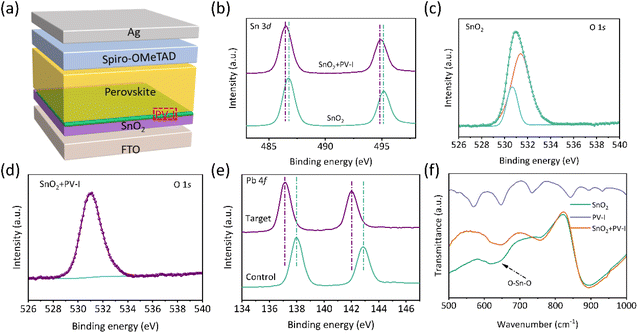
The device used in this work is FTO/SnO2/(PV-I)/perovskite (PVK)/spiro-OMeTAD/Ag as presented in Fig. 1a, where PV-I was introduced into the interface between SnO2 and PVK, which is expected to improve the performance of PSCs. Fig. S1† shows the structure of PV-I. First, X-ray photoelectron spectroscopy (XPS) and Fourier-transform infrared (FTIR) spectroscopy were employed to investigate the interaction of PV-I with SnO2 and PVK. Fig. 1b shows the Sn 3d peaks of SnO2 and SnO2/PV-I. The peak positions were shifted towards lower binding energy after introducing PV-I on SnO2, indicating that the electron cloud density increased, which is mainly due to the strong chemical interaction between C![[double bond, length as m-dash]](https://www.rsc.org/images/entities/char_e001.gif) O and Sn2+. In order to further prove the interaction, O 1s was further tested and shown in Fig. 1c and d. As we all know the oxygen vacancies can be reduced if there is indeed an interaction between SnO2 and PV-I. Generally, the lower binding energy is always assigned to the signal of oxygen vacancies, while the higher binding energy can be assigned to the signal of lattice oxygen. After modification with PV-I, the peak areas of the oxygen vacancy reduced significantly, indicating that there is a strong chemical interaction between PV-I and SnO2. In addition, the chemical interaction between PVK and PV-I was further proved by XPS and is shown in Fig. 1e. The peak of Pb 4f in the control perovskite film is shifted to lower binding energy after PV-I modification, suggesting that there is also a chemical interaction between PV-I and PVK.3 FTIR spectra were further used to investigate the chemical interaction in the device. Fig. S2† shows the full FTIR spectrum of SnO2 with and without PV-I modification. As shown in Fig. 1f, the peak at 600–700 cm−1 can be assigned to the stretching vibration of O–Sn–O.10 Obviously, the shift indicates the chemical interaction in SnO2 and PV-I, which supports the above XPS results. Fig. S3† shows the FTIR spectra of PVK and PV-I/PVK, and the peaks located at 600 cm−1 and 895 cm−1 are considered to be related to N–H vibration.9,12,26,27 The peak positions in PVK are shifted to a lower wavenumber after PV-I modification, which may be related to the formation of hydrogen bonds between PV-I and PVK. In a word, the above results indicate that the chemical interaction of PV-I with SnO2 and PVK can be formed after introducing PV-I.
O and Sn2+. In order to further prove the interaction, O 1s was further tested and shown in Fig. 1c and d. As we all know the oxygen vacancies can be reduced if there is indeed an interaction between SnO2 and PV-I. Generally, the lower binding energy is always assigned to the signal of oxygen vacancies, while the higher binding energy can be assigned to the signal of lattice oxygen. After modification with PV-I, the peak areas of the oxygen vacancy reduced significantly, indicating that there is a strong chemical interaction between PV-I and SnO2. In addition, the chemical interaction between PVK and PV-I was further proved by XPS and is shown in Fig. 1e. The peak of Pb 4f in the control perovskite film is shifted to lower binding energy after PV-I modification, suggesting that there is also a chemical interaction between PV-I and PVK.3 FTIR spectra were further used to investigate the chemical interaction in the device. Fig. S2† shows the full FTIR spectrum of SnO2 with and without PV-I modification. As shown in Fig. 1f, the peak at 600–700 cm−1 can be assigned to the stretching vibration of O–Sn–O.10 Obviously, the shift indicates the chemical interaction in SnO2 and PV-I, which supports the above XPS results. Fig. S3† shows the FTIR spectra of PVK and PV-I/PVK, and the peaks located at 600 cm−1 and 895 cm−1 are considered to be related to N–H vibration.9,12,26,27 The peak positions in PVK are shifted to a lower wavenumber after PV-I modification, which may be related to the formation of hydrogen bonds between PV-I and PVK. In a word, the above results indicate that the chemical interaction of PV-I with SnO2 and PVK can be formed after introducing PV-I.
To confirm the effect of PV-I on perovskite film quality and morphology, a series of technologies were used. First, UV–vis spectroscopy was used to reveal the effect of PV-I on film absorbance. First, the bandgap of the perovskite film was calculated using Tauc plots and is shown in Fig. S4.† As shown in Fig. 2a, the absorption intensity of the target perovskite film was slightly increased after the addition of PV-I, which can be due to the improved film quality and increased coverage.13 The XRD result further indicates that the quality of the perovskite film was improved after PV-I modification, which is due to the increase of the peak intensity after the introduction of PV-I on SnO2 (Fig. 2b). The scanning electron microscopy (SEM) images of perovskite films deposited on SnO2 without and with PV-I modification are shown in Fig. 2c and d. The grain size slightly increased after the deposition of PV-I on SnO2 (Fig. S5†), which was mainly due to the change of the substrate. In addition, the increased absorbance also can be attributed to the increase in the grain size and the improvement in the film quality. The improved film quality can be due to the several different kinds of functional groups in PV-I, which can not only enhance the interface connection but also passivate anionic defects (e.g., Pb–I antisite defects and formamidinium (FA+) or methylammonium (MA+) vacancies) and cationic defects (e.g., undercoordinated Pb).
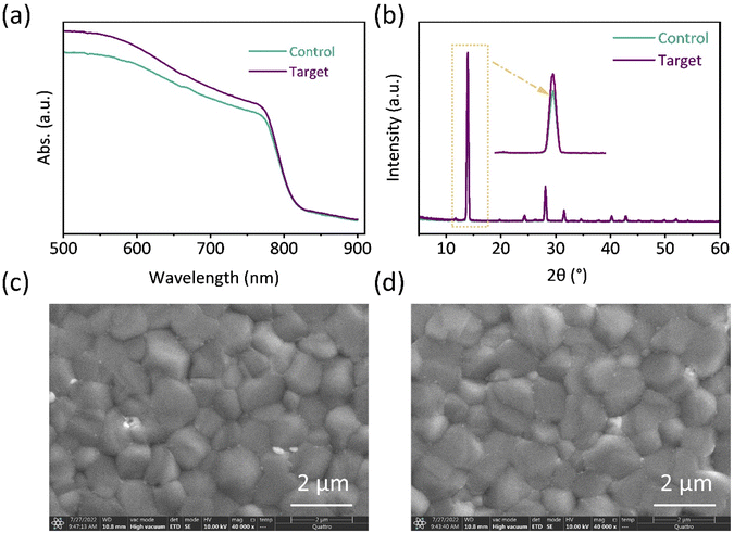 | ||
| Fig. 2 (a) UV–vis spectra and (b) XRD patterns of the film deposited on FTO/SnO2 or FTO/SnO2/PV-I. SEM image of the perovskite film (c) without or (d) with PV-I modification. | ||
As discussed in previous works, residual stress and film orientation are important for the device's performance. First, depth-dependent grazing incident X-ray diffraction (GIXRD) measurements have been successfully used to investigate the stress distribution of perovskite films.9,19Fig. 3a and b show the GIXRD result of the film without and with PV-I modification. Different incident angles (ω) were chosen to investigate the stress at different depths. As shown in Fig. 3a, for the control film, a significant peak shift can be seen at different depths, indicating that there is a large amount of residual stress in the film. Although PV-I was introduced into the interface between SnO2 and PVK (Fig. 3b), the peak positions were the same at different depths, suggesting that the stress had been released. The released stress after PV-I modification could be related to the effective passivation of interfacial defects. It was reported that the interfacial stress can be effectively released through incorporating WS2 at the ETL/CsPbBr3 interface, which is considered to act as a “lubricant” between the ETL and the perovskite.17 In this work, PV-I can play a similar role to the previous work because PV-I can form chemical connections with SnO2 and the perovskite layer, as well as passivate interfacial defects. Polar diagram measurement was further employed to investigate the effect of PV-I on film orientation. Here, the characteristic crystal plane (001) facet was chosen for polar diagram measurement, as shown in Fig. 3c and d. Bright spots are shown in both polar figures, indicating that the film has an obvious orientation whether with or without PV-I modification. However, a slight shift can be observed in the control film while not in the target film, proving that the target film may have a better orientation than the control film. The slightly improved orientation can be attributed to the change in the substance and chemical interactions between PV-I and the perovskite.
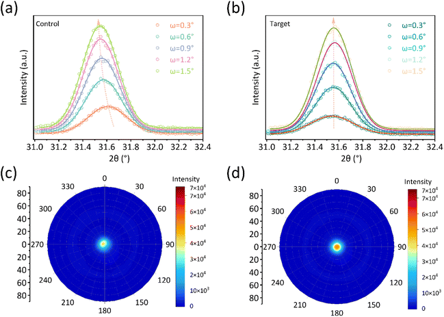 | ||
| Fig. 3 GIXRD spectra of the perovskite film deposited on (a) FTO/SnO2 and (b) FTO/SnO2/PV-I. Pole figure measurements along the (001) facet (c) with and (d) without PV-I modification. | ||
Subsequently, photoluminescence (PL) and time-resolved photoluminescence (TRPL) spectra were recorded to investigate the effect of PV-I interface modification on the carrier lifetimes of perovskite films (Fig. 4a and b, the device structure: glass/(PV-I)/PVK). As shown in Fig. 4a, the enhanced PL intensity for PVK after PV-I modification indicates that the defects of the film were reduced, which again supports the improved film quality in the above XRD analysis. TRPL decay curves are presented in Fig. 4b, and are fitted by the following formula:25I(t) = I0 + A1![[thin space (1/6-em)]](https://www.rsc.org/images/entities/char_2009.gif) exp(−t/τ1) + A2
exp(−t/τ1) + A2![[thin space (1/6-em)]](https://www.rsc.org/images/entities/char_2009.gif) exp(−t/τ2), where A1 and A2 represent decay amplitudes, and τ1 and τ2 are related to nonradiative recombination and radiative recombination, respectively. The average lifetime (τavg) can be measured from the following equation:28τavg = (A1τ12 + A2τ22)/(A1τ1 + A2τ2). As can see in Table S1,† the carrier lifetime increases from 413.7 ns of the control to 907.4 ns of the target, suggesting that the film defects and carrier annihilation sites are effectively reduced for PVK after PV-I treatment. The improved PL intensity and carrier lifetime can be due to the improved film quality.
exp(−t/τ2), where A1 and A2 represent decay amplitudes, and τ1 and τ2 are related to nonradiative recombination and radiative recombination, respectively. The average lifetime (τavg) can be measured from the following equation:28τavg = (A1τ12 + A2τ22)/(A1τ1 + A2τ2). As can see in Table S1,† the carrier lifetime increases from 413.7 ns of the control to 907.4 ns of the target, suggesting that the film defects and carrier annihilation sites are effectively reduced for PVK after PV-I treatment. The improved PL intensity and carrier lifetime can be due to the improved film quality.
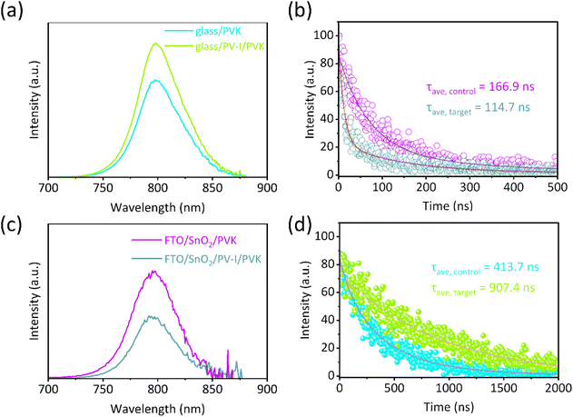 | ||
| Fig. 4 (a) PL and (b) TRPL spectra with the structure of glass/(PV-I)/PVK. (c) PL and (d) TRPL spectra of the perovskite films deposited on FTO/SnO2 without and with PV-I modification. | ||
PL and TRPL with the structures of FTO/SnO2/PVK and FTO/SnO2/PV-I/PVK were also measured, which is helpful to further understand the kinetic process of interfacial charge extraction for the PSCs without or with PV-I. As shown in Fig. 4c, the PL intensity of the perovskite films deposited on FTO/SnO2/PV-I was reduced compared with that of films deposited on FTO/SnO2. Carrier lifetime was also evaluated by TRPL, and the results are shown in Fig. 4d and Table S2.† After PV-I modification, the carrier lifetime of the control film is 166.9 ns, while that of the target film is 114.7 ns. The weaker PL intensity and shorter carrier lifetime prove that the PV-I-modified device can exhibit better carrier extraction and transmission performance. Fig. S6† shows the relationship between the light intensity and the open voltage (VOC), and the ideality factor (n) derived from the slope of the correlation curve can reflect the nonradiative recombination of the device.29 Generally, the closer n is to 1, the smaller the loss of non-radiative recombination for the device. It can be found that n decreases from 1.86 for the control device to 1.44 for the target device, which proves that the loss of non-radiative recombination can be inhibited after PV-I modification.
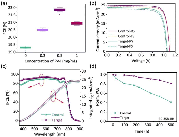
Significant non-radiative recombination suppression and improved film quality encourage us to further explore device performance. The performance of the devices prepared with different concentrations of PV-I was evaluated, as shown in Fig. 5a and Fig. S7.† There is an obvious increase in the PCE as the concentration of PV-I increases. The best PCE of PSCs was obtained when the concentration of PV-I was 0.5 mg ml−1. Fig. 5b shows the J–V curves of the PSCs with and without PV-I modification. Compared with the champion control device with a PCE of 19.41% (a JSC of 23.73 mA cm−2, a VOC of 1.05 V, and an FF of 0.774), the champion devices with PV-I achieved a PCE of 22.02% (a JSC of 24.69 mA cm−2, a VOC of 1.11 V and an FF of 0.802). In order to verify the feasibility of this strategy, we further prepared devices in Hou's lab, and the results showed that the efficiency exceeded 22%. Fig. 5c shows the corresponding incident photon-to-electron conversion efficiency (IPCE) spectra of the best-performing control device and PV-I modified device. The integrated current densities of the control device and the target device are 23.44 mA cm−2 and 24.47 mA cm−2, respectively, which are in good agreement with the J–V characterization. Long-term stability was further measured to evaluate the potential commercial advantages of the strategy proposed in this work. As shown in Fig. 5d, the unpackaged device was placed in an air environment with a relative humidity of 30–35%. After aging 500 h, the control device drops to 41%, while the champion device drops to only 19%. Fig. S8† shows the photostability of the devices with or without PV-I modification placed under one sun illumination where the devices were located in a glove box. After being maintained for 100 h, up to 89% of its original PCE was maintained for the device with PV-I, whereas this was only 80% for the control device. The enhanced PCE and improved stability are mainly due to the improved film quality and the reduction, which reduce the attack sites of water and oxygen, thereby slowing down the aging of the device.
Conclusions
In conclusion, a novel buried interface molecule named PV-I was used to modify the interface between perovskite and SnO2, and PV-I acts as a bridge to improve the interface connection. At the same time, the strong chemical effect reduces the film defects of SnO2 and the perovskite, which is beneficial to carrier transport. On the other hand, due to the characteristics and multifunctional groups of PV-I, the interfacial stress of the perovskite film is not only released effectively but also oriented more obviously, which is also beneficial to the transport of the carrier. Finally, the PCE of PSCs modified with PV-I improved over 22% (0.1 cm2) and the stability of the device has also been significantly improved. This work not only provides an effective method to improve the PCE and stability of PSCs but also gives a straightforward strategy for the commercialization process.Author contributions
Hanjun Zou: validation; resources; investigation; and formal analysis. Huan Bi: conceptualization; validation; investigation; formal analysis; writing – original draft; and writing – review and editing. Yongheng Chen and Mengna Guo: validation; data curation; and resources. Wenjing Hou and Pengyu Su: supervision; resources. Kai Zhou, Chuanyao Yang, and Xiangnan Gong: visualization; formal analysis. Li Xiao: funding acquisition. Li Liu: validation; resources; writing – review and editing; supervision; and funding acquisition.Conflicts of interest
The authors declare no conflict of interest.Acknowledgements
This work was financially supported by the Doctoral Fund of Southwest University of Science and Technology (no. 21zx7111), the Natural Science Fundation of Chongqing (grant no. cstc2021jcyj-bshX0219), and the Science and Technology Research Program of Chongqing Municipal Education Commission (grant no. KJQN202201137). We would like to acknowledge Prof. Qing Shen (Faculty of Informatics and Engineering, The University of Electro-Communications) for the useful discussion. We also acknowledge the support of Shiyanjia Lab (https://www.shiyanjia.com). We would like to thank the Analytical and Testing Center of Chongqing University for various measurements.References
- A. Kojima, K. Teshima, Y. Shirai and T. Miyasaka, J. Am. Chem. Soc., 2009, 131, 6050–6051 CrossRef CAS PubMed.
- NREL, Best Research-Cell Efficiency Chart, https://www.nrel.gov/pv/cell-efficiency.html.
- F. Zhang, S. Ye, H. Zhang, F. Zhou, Y. Hao, H. Cai, J. Song and J. Qu, Nano Energy, 2021, 89, 106370 CrossRef CAS.
- Z. Guo, A. K. Jena, G. M. Kim and T. Miyasaka, Energy Environ. Sci., 2022, 15, 3171–3222 RSC.
- W. Yu, X. Sun, M. Xiao, T. Hou, X. Liu, B. Zheng, H. Yu, M. Zhang, Y. Huang and X. Hao, Nano Res., 2022, 15, 85–103 CrossRef CAS.
- S. Yang, Y. Duan, Z. Liu and S. Liu, Adv. Energy Mater., 2022, 2201733, DOI:10.1002/aenm.202201733.
- Z. Wang, L. Liu, X. Liu, D. Song, D. Shi, S. Wu, Y. Tong, H. Ren, M. Li, Y. Zheng and D. Zhao, Chem. Eng. J., 2022, 432, 134367 CrossRef CAS.
- Y. Cheng, Q. Wei, Z. Ye, X. Zhang, P. Ji, N. Wang, L. Zan, F. Fu and S. Liu, Sol. RRL, 2022, 6, 2200418 CrossRef CAS.
- H. Bi, B. Liu, D. He, L. Bai, W. Wang, Z. Zang and J. Chen, Chem. Eng. J., 2021, 418, 129375 CrossRef CAS.
- H. Bi, X. Zuo, B. Liu, D. He, L. Bai, W. Wang, X. Li, Z. Xiao, K. Sun, Q. Song, Z. Zang and J. Chen, J. Mater. Chem. A, 2021, 9, 3940–3951 RSC.
- P. Zhang, Y. Chen, S. Wu, X. Li, M. Liu and S. Li, Nanoscale, 2021, 14, 35–41 RSC.
- H. Bi, G. Han, M. Guo, C. Ding, S. Hayase, H. Zou, Q. Shen, Y. Guo and W. Hou, Sol. RRL, 2022, 6, 2200352 CrossRef CAS.
- H. Bi, Y. Guo, M. Guo, C. Ding, S. Hayase, T. Mou, Q. Shen, G. Han and W. Hou, Chem. Eng. J., 2022, 439, 135671 CrossRef CAS.
- H. Wang, C. Zhu, L. Liu, S. Ma, P. Liu, J. Wu, C. Shi, Q. Du, Y. Hao, S. Xiang, H. Chen, P. Chen, Y. Bai, H. Zhou, Y. Li and Q. Chen, Adv. Mater., 2019, 31, 1904408 CrossRef CAS PubMed.
- N. Rolston, K. A. Bush, A. D. Printz, A. Gold-Parker, Y. Ding, M. F. Toney, M. D. McGehee and R. H. Dauskardt, Adv. Energy Mater., 2018, 8, 1802139 CrossRef.
- G. Kim, H. Min, K. S. Lee, D. Y. Lee, S. M. Yoon and S. I. Seok, Science, 2020, 370, 108–112 CrossRef CAS PubMed.
- Q. Zhou, J. Duan, X. Yang, Y. Duan and Q. Tang, Angew. Chem., Int. Ed., 2020, 59, 21997 CrossRef CAS PubMed.
- C. C. Zhang, S. Yuan, Y. H. Lou, Q. W. Liu, M. Li, H. Okada and Z. K. Wang, Adv. Mater., 2020, 32, 2001479 CrossRef CAS PubMed.
- H. Bi, Y. Guo, M. Guo, C. Ding, S. Hayase, T. Mou, Q. Shen, G. Han and W. Hou, Chem. Eng. J., 2022, 439, 135671 CrossRef CAS.
- R. Saraf and V. Maheshwari, ACS Appl. Energy Mater., 2019, 2, 2214–2222 CrossRef CAS.
- Z. Yao, D. Qu, Y. Guo and H. Huang, Org. Electron., 2019, 70, 205–210 CrossRef CAS.
- H. Xiong, G. DeLuca, Y. Rui, B. Zhang, Y. Li, Q. Zhang, H. Wang and E. Reichmanis, ACS Appl. Mater. Interfaces, 2018, 10, 35385–35394 CrossRef CAS PubMed.
- W. Xiang, Q. Chen, Y. Wang, M. Liu, F. Huang, T. Bu, T. Wang, Y.-B. Cheng, X. Gong, J. Zhong, P. Liu, X. Yao and X. Zhao, J. Mater. Chem. A, 2017, 5, 5486–5494 RSC.
- N. Yang, C. Zhu, Y. Chen, H. Zai, C. Wang, X. Wang, H. Wang, S. Ma, Z. Gao, X. Wang, J. Hong, Y. Bai, H. Zhou, B.-B. Cui and Q. Chen, Energy Environ. Sci., 2020, 13, 4344–4352 RSC.
- D. Bi, C. Yi, J. Luo, J.-D. Décoppet, F. Zhang, S. M. Zakeeruddin, X. Li, A. Hagfeldt and M. Grätzel, Nat. Energy, 2016, 1, 16142 CrossRef CAS.
- N. Li, X. Niu, Q. Chen and H. Zhou, Chem. Soc. Rev., 2020, 49, 8235–8286 RSC.
- N. Li, S. Tao, Y. Chen, X. Niu, C. K. Onwudinanti, C. Hu, Z. Qiu, Z. Xu, G. Zheng, L. Wang, Y. Zhang, L. Li, H. Liu, Y. Lun, J. Hong, X. Wang, Y. Liu, H. Xie, Y. Gao, Y. Bai, S. Yang, G. Brocks, Q. Chen and H. Zhou, Nat. Energy, 2019, 4, 408–415 CrossRef CAS.
- R. Zhao, L. Xie, R. Zhuang, T. Wu, R. Zhao, L. Wang, L. Sun and Y. Hua, ACS Energy Lett., 2021, 6, 4209–4219 CrossRef CAS.
- Y. Ning, L. Lv, Y. Lu, C. Zhang, Y. Fang, A. Tang, Y. Hu, Z. Lou, F. Teng and Y. Hou, Phys. Status Solidi RRL, 2015, 9, 120–124 CrossRef CAS.
Footnote |
| † Electronic supplementary information (ESI) available. See DOI: https://doi.org/10.1039/d2nr06290a |
| This journal is © The Royal Society of Chemistry 2023 |

