
 Open Access Article
 This Open Access Article is licensed under a
 Creative Commons Attribution 3.0 Unported Licence
Creation of ordered 3D tubes out of DNA origami lattices†
Johannes M.
Parikka
 a,
Heini
Järvinen‡
a,
Karolina
Sokołowska§
a,
Visa
Ruokolainen
b,
Nemanja
Markešević
a,
Ashwin K.
Natarajan¶
c,
Maija
Vihinen-Ranta
b,
Anton
Kuzyk
c,
Kosti
Tapio||
*a and
J. Jussi
Toppari
*a
a,
Heini
Järvinen‡
a,
Karolina
Sokołowska§
a,
Visa
Ruokolainen
b,
Nemanja
Markešević
a,
Ashwin K.
Natarajan¶
c,
Maija
Vihinen-Ranta
b,
Anton
Kuzyk
c,
Kosti
Tapio||
*a and
J. Jussi
Toppari
*a
aUniversity of Jyväskylä, Department of Physics and Nanoscience Center, 40014 University of Jyväskylä, Finland. E-mail: kosti.tapio@aalto.fi; j.jussi.toppari@jyu.fi
bUniversity of Jyväskylä, Department of Biological and Environmental Science and Nanoscience Center, 40014 University of Jyväskylä, Finland
cDepartment of Neuroscience and Biomedical Engineering, Aalto University, 00076 Aalto, Finland
First published on 28th March 2023
Abstract
Hierarchical self-assembly of nanostructures with addressable complexity has been a promising route for realizing novel functional materials. Traditionally, the fabrication of such structures on a large scale has been achievable using top-down methods but with the cost of complexity of the fabrication equipment versus resolution and limitation mainly to 2D structures. More recently bottom-up methods using molecules like DNA have gained attention due to the advantages of low fabrication costs, high resolution and simplicity in an extension of the methods to the third dimension. One of the more promising bottom-up techniques is DNA origami due to the robust self-assembly of arbitrarily shaped nanostructures with feature sizes down to a few nanometers. Here, we show that under specific ionic conditions of the buffer, the employed plus-shaped, blunt-ended Seeman tile (ST) origami forms elongated, ordered 2D lattices, which are further rolled into 3D tubes in solution. Imaging structures on a surface by atomic force microscopy reveals ribbon-like structures, with single or double layers of the origami lattice. Further studies of the double-layered structures in a liquid state by confocal microscopy and cryo-TEM revealed elongated tube structures with a relatively uniform width but with a varying length. Through meticulous study, we concluded that the assembly process of these 3D DNA origami tubes is heavily dependent on the concentration of both mono- and divalent cations. In particular, nickel seems to act as a trigger for the formation of the tubular assemblies in liquid.
Introduction
Hierarchical assemblies have shown huge potential in recent decades1–4 for new innovations in the fields of nano-optics,5–7 drug delivery8–10 and nanoelectronics.11–13 Especially in the field of nano-optics, the surfaces coated with such assemblies can produce novel properties like negative refractive index, which could pave the way for applications such as superlenses.14,15 However, these structures place special constraints on fabrication due to the requirement for small feature sizes, and high spatial and orientational control simultaneously with high yield and scalability. The orientation control, and in most cases, the resolution, can be achieved with traditional top-down methods like focused ion beam (FIB),16 electron beam (EBL),17 and ultraviolet (UV)14,18,19 lithographies. However, high yields and upscaling become exceedingly difficult and/or expensive.Recently, bottom-up approaches have gained popularity in the fabrication of hierarchical assemblies due to the advantages of reduced cost and simpler fabrication methods.20–22 In this context, DNA has proven to be a versatile molecule to fabricate and functionalize nanoconstructs due to its robust self-assembly properties and a variety of different functionalization possibilities.23 While there exists a plethora of different nanoscale DNA-based assemblies,24 micrometer-scale or larger structures are more difficult to fabricate. Yet, these contain key components for future innovations,25–27 since each building block can be addressed and functionalized to perform a certain task.
Within the field of structural DNA nanotechnology, one of the most promising methods is the DNA origami technique due to its ability to create almost arbitrary 3D shapes with feature sizes down to a few nanometers and to functionalize any position along the origami with sub-nanometer accuracy.2,3,28 Previously, different kinds of DNA origami have been used to fabricate different hierarchical 2D and 3D structures, both on surfaces and in liquid.3,29,30,53 Both blunt-end stacking and DNA hybridization have been utilized to achieve the ordered structures, but the role of the buffer conditions on the formation of the ordered structures has not been thoroughly explored.
Here, we demonstrate the formation of 3D, micrometer-size tubular DNA origami assemblies in solution mediated by appropriate ionic conditions, as illustrated in Scheme 1. The choice for the DNA origami structure was a twist-corrected and blunt-ended version31 of the so-called Seeman tile (ST) origami32 due to the 4-fold rotational symmetry that enables the growth of a symmetric square lattice via the non-specific blunt-end stacking of DNA helices.31,33 We investigated and demonstrated the effect of different commonly used cations, namely sodium, magnesium, nickel and potassium on lattice and tube formation. We observed that in solutions of high enough ionic strength, the STs form either 2D, elongated, single-layer square lattices (ribbons) or directionally grown tubes, i.e., rolled square lattices. In particular, nickel seems to act as a trigger for the formation of the tubular assemblies. The ordered directional growth and the further rolling into a tube are achieved by adjusting the combination and concentrations of mono- and divalent cations during the incubation process.
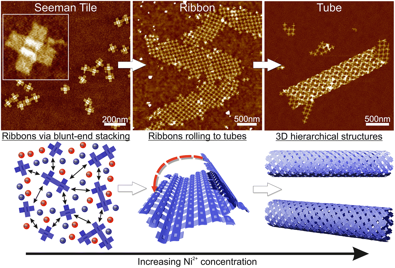 | ||
| Scheme 1 Schematic view of the formation of the hierarchical nanostructures using the Seeman tile (ST) origami and electrostatic interaction. The lower row sketches the behavior of STs with increasing Ni2+ concentration, while the upper row shows the corresponding AFM images. Left column: at low Ni2+ concentration, the DNA origami are repulsed from each other due to coulombic interaction between the negatively charged origami. The mono- and divalent cations (blue/red circles) screen the repulsion to allow some blunt-end stacking (black arrow). The AFM inset size is 125 nm × 125 nm. Middle column: when the Ni2+ concentration is increased, the STs initially form 2D ribbons. Right column: in high enough Ni2+ concentration, the ribbons roll into 3D tubes. | ||
Even the orientation of each origami within the formed ribbons and tubes is not fully controlled due to the non-specificity of the blunt-end stacking, and they are still organized with highly ordered directionality, spacing and final 3D shape. Since each origami can be functionalized with different inorganic and organic nanomaterials,23,24 such as proteins, lipids and nanoparticles, one can form many interesting and useful highly organized structures like plasmonic entities with highly controlled spacing and order of the metallic nanoparticles along the shape of ribbons or tubes.
Experimental section
The DNA origami oligonucleotides were purchased from Thermo Fisher (Waltham, Massachusetts, USA). The M13mp18 scaffold strand was bought from Tilibit Nanosystems (Munich, Germany). The origami concentration was measured using a NanoDrop One C Microvolume UV-vis spectrophotometer (Thermo Fisher Scientific). Mica V1 disc (Ted Pella) substrates were purchased from Caspilor Aktiebolag. Silicon chips were acquired from Si-Mat. Magnesium chloride hexahydrate (purity 99.0–101.0%), nickel chloride hexahydrate (min. 96.0%), sodium chloride and disodium EDTA dihydrate (99–101.0%) were acquired from Merck. Tris base (99.9%) was acquired from Sigma Aldrich. A Bruker Dimension Icon atomic force microscope (AFM) equipped with Bruker ScanAsyst-Air tips (nominal radius of 2 nm) was used in the imaging (Billerica, Massachusetts, USA). FinnSonic M3 ultrasonic cleaner was used for the sonication of silicon chips. An Oxford Plasmalab 80 Plus reactive ion etcher (RIE) was used to clean and treat the silicon substrates (Tubney Woods, Abingdon, UK).DNA origami folding and purification
DNA origami was folded as reported before.28 Both unpurified and purified DNA origami solutions were used in the experiments: the confocal and the cryo-TEM samples were prepared without purification, while both the unpurified and purified origami were used in the deposition on silicon. In general, no differences were observed between the purified and the unpurified sample concerning the formation of the ribbons, and we mainly used purified samples for the silicon deposition.The DNA origami solution was purified by ultrafiltration using 100 kDa Amicon Ultra 0.5 mL centrifugal filters just after folding the origami: 100 μL of the folded origami solution was mixed with 400 μL of the origami buffer (1× TAE/12.5 mM MgCl2). The solution was pipetted to a 100 kDa Amicon filter and spanned down at 14![[thin space (1/6-em)]](https://www.rsc.org/images/entities/char_2009.gif) 000 rcf for 3 min. The supernatant was discarded and 400 μL of the origami buffer was added to the filter. After mixing, centrifugation was repeated. In total, the sample was centrifuged 3 times for 3 min and the last run for 5 min. After the last run, the filter was placed upside-down in a new tube for collection of the sample (1000 rcf, 2 min). The volume of the sample was adjusted back to 100 μL using the origami buffer. Typical origami concentrations after folding and purification were 10–20 nM.
000 rcf for 3 min. The supernatant was discarded and 400 μL of the origami buffer was added to the filter. After mixing, centrifugation was repeated. In total, the sample was centrifuged 3 times for 3 min and the last run for 5 min. After the last run, the filter was placed upside-down in a new tube for collection of the sample (1000 rcf, 2 min). The volume of the sample was adjusted back to 100 μL using the origami buffer. Typical origami concentrations after folding and purification were 10–20 nM.
Imaging of the assembled origami ribbons on silicon
The 7 mm × 7 mm silicon chips were cut using a diamond cutter. Both sides of the chips were cleaned by immersing the chip in boiling acetone for 2–3 minutes and rubbing both sides using a cotton stick. After both sides were cleaned, the chips were immersed for a few minutes more in boiling acetone and then rinsed using room temperature acetone. Finally, the chips were sonicated in isopropanol (IPA) at 30 °C for 3 min and dried using N2 flow.Before the origami deposition, the silicon surfaces were treated with O2 plasma in the RIE for 20 min at 30 °C, while the O2 flow was 50 sccm, the pressure was 40 mTorr and the RF power was 200 W. The chips were used soon after the treatment, usually within 30 min after the plasma was switched off. Longer waiting times would result in the vanishing of the obtained hydrophilicity.
The different cation buffers (sodium, magnesium, nickel and potassium) were mixed and the origami solution was added just before the deposition so that the final origami concentration was 10 nM and the ionic strength was appropriate. The deposition time varied between 30 and 45 min. Then, the surface was washed by adding 40–80 μL of Milli-Q water back and forth 3–4 times from the edge of the chip and the water was discarded. The washing step was repeated 5 times before drying the chip by N2 flow.
Preparation and measurement of ribbons in the cryo-TEM
The cryo-TEM samples were prepared as follows: 5 μL of DNA origami solution (50 mM MgCl2, 5 mM NiCl2, 250 mM NaCl, 1× TAE and 5 nM origami) was dropped on a plasma-cleaned (30 s with 20 W forward power and 2 W reverse power, NanoClean model 1070, Fischione Instruments) R3.5/1 quantifoil TEM grid in a Leica Automatic Plunge Freezer EM GP2 maintained at 22 °C with 90% relative humidity. The sample was blotted for 2.8 s and plunged immediately into liquid ethane. The grids were transferred to a JEOL JEM-3200FSC field emission cryo-TEM operated at 300 kV in bright field mode with an Omega-type zero-loss energy filter. Imaging was done with a Gatan Ultrascan 4000 camera with a total exposure of 20 e− Å−2.Confocal microscopy characterization of the ribbons
The structures were stained with Hoechst 33342 (2 μg mL−1) DNA-specific dye and imaged with a Leica SP 8 confocal microscope. The samples were excited using a 405 nm laser and detected between 412 and 652 nm with a Leica hybrid detector. The samples were observed using a Leica HC PL APO CS2 (63×, N.A. 1.2) water immersion objective. A voxel size of 68 × 68 × 180 nm (Fig. 4C) and 68 × 68 × 356 nm was used to acquire the confocal data. A voxel size of 33 × 33 × 157 nm was used for the deconvolved images (Fig. S4A and S4B†) and the deconvolution was done using a Leica Lightning system. In the overview confocal shown in Fig. S4C,† the pixel size was 210 × 210 nm.Data analysis was performed using Fiji software. The tube length was measured only when the beginning and end of the tube were distinguished by drawing a straight line between the two points. In the case of a long tube with angles in between, such as that shown in Fig. 4C, the tube length was determined by dividing the tube into several individual, straight tubes. The widths of the tubes were determined by measuring the intensity profiles perpendicular to the tube length every 0.5–1 μm along the tube, and by manually evaluating the tube width from the intensity profiles.
Characterization of ribbons using dynamic light scattering
Characterization by dynamic light scattering (DLS) was done separately for individual Seeman tiles (within an annealing buffer of 1× TAE/12.5 mM MgCl2), ribbons and ribbons with EDTA. In each case, 80–120 μL of the sample was pipetted to a DLS cuvette (Malvern ZEN0040) and subsequently measured in backscatter configuration for around 1 h, i.e., 26 repeats of 20 × 6.71 s measurements. Attenuation was set to 9, equilibrium time between the cycles to 0 s and temperature to 25 °C. Data were measured/fitted with multiple narrow distribution modes with index of refraction for the origami set to 1.54.34 We analyzed each 1 h DLS run by plotting the collected statistics of the size distributions within three subsequent 20 min parts: the first 20 min, the middle (20–40 min) and the last (40–60 min). See Fig. S9† for individual DLS distributions.In each sample, the origami concentration was set to 10 nM. The ribbon sample had a cation buffer with 5 mM Ni2+, 50 mM Mg2+ and 250 mM Na+, and the measurements started right after the origami samples were mixed with the buffer. After the ribbon sample was incubated and measured for 1 h, the EDTA concentration in solution was fixed to 40 mM and the DLS measurement started again immediately. The goal was to analyse the reversibility of ribbon structures in the presence of EDTA. EDTA was chosen because of its well-known chelating capabilities regarding divalent cations,35,36 in our case Mg2+ and Ni2+.
Results and discussion
The fundamental building block of our hierarchical assemblies is a twist-corrected and blunt-ended version31 of the 4-fold symmetric plus-shaped DNA origami called the Seeman tile (ST),32 as shown in Scheme 1. The origami has four arms protruding outwards from the middle crossing. Each arm has 12 helices, which can attach to any arm of another origami via blunt-end stacking. Under the low salt conditions, i.e., the storage conditions (1× TAE/12.5 mM MgCl2), the repulsion between the negatively charged origami keeps them mainly separated so that the blunt-end stacking interactions and thus the lattice formation are limited. By increasing the overall salt concentration of the solution, the STs start to bind with each other on a larger scale, thus enabling the assembly into ordered 2D or 3D structures.Here, we set out to identify the conditions in which these structures form and investigate the effect of each used cation (sodium, magnesium, nickel and potassium). A similar strategy was employed by Hayakawa et al. to assemble triangular origami into tubes but only using magnesium.37 Also, Li et al. have used smaller four-point-star tiles to assemble tubes using sticky ends in the presence of magnesium and sodium cations.38 We extend these discussions to show that other cations can also play a crucial role in the formation of DNA origami assemblies via blunt-end stacking.
The starting point was based on previous experiments conducted by Shen et al.,6 Rafat et al.,31 and the Rothemund group.39 Initially, we tested the effect of magnesium on the structural formation by altering the concentration between 100 and 700 mM. Fig. 1A–F show the results of 100–300 mM MgCl2. Additional images at 500 and 700 mM MgCl2 are shown in Fig. S1,† revealing only separate STs or huge aggregates. At Mg2+ concentrations under 100 mM, only a few individual origami attached to the silicon surface and were not removed during the washing step. As seen in Fig. 1, the increase in Mg2+ concentration leads from initial small lattices to the formation of large aggregates, which is expected since divalent cations like magnesium can attach the origami to each other. It is not possible to achieve a condition to allow the systematic deposition or the formation of well-ordered shapes. Merely, increasing the Mg2+ concentration assembles the aggregation just faster and deposition to Si more efficient, which results in more randomly located and larger aggregates in the AFM images, as illustrated in Fig. 1. To prevent this, usually, monovalent cations such as sodium are used during the assembly.
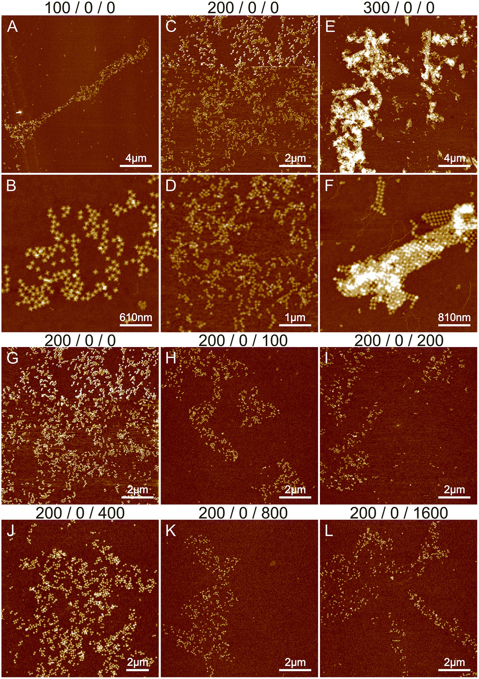 | ||
| Fig. 1 The effects of Mg2+ and Na+ ions on lattice formation. The buffer conditions are listed on top of the images as: CMg2+/CNi2+/CNa+. (A and B), (C and D) and (E and F) show the AFM images of STs deposited in 1× TAE and either 100 mM, 200 mM or 300 mM MgCl2 buffer, respectively. (G–L) The effect of Na+ ions on lattice formation. The concentration of Mg2+ remains constant at 200 mM while the concentration of Na+ is varied between 0 and 1600 mM. | ||
The effect of sodium was investigated by varying its concentration between 0 and 1600 mM. Since the threshold between smaller lattices and aggregation in the case of magnesium was around 200 mM (see Fig. 1B and E), we fixed the Mg2+ concentration to this value during the sodium experiments. The results are shown in Fig. 1G–L and S2.† Increasing the sodium concentration reduces the formation of aggregates because Na+ ions replace more Mg2+ ions and as a monovalent cation it does not cause attraction between the origami. This unfortunately also prevents the formation of lattices and more individual origami are seen on the surface. In general, the overall coverage of the origami shown in Fig. 1 is slowly diminished as the number of Na+ ions is increased, because the origami sticks less to the surface due to the monovalent charge of Na+ ions compared to Mg2+ ions. Also, the origami seems to agglomerate at higher Na+ concentrations resembling drying patterns. Overall, the results indicate that using only Na+ and Mg2+ leads to either aggregation or repulsion of origami depending on the concentration of the cations.
Since the presence of magnesium and sodium only causes either small lattices or aggregations, we hypothesize that a third element is required to facilitate a more controllable growth process. It has been reported in the literature that nickel can be used to stabilize and guide the growth process of DNA structures, which involves weak interactions, such as blunt-end stacking.40–42 Additionally, Ni2+ is a divalent cation like Mg2+ and acts as an even stronger adhesive. Since the effect of nickel is not well known, we started to experiment by using low Ni2+ concentrations and adjusting that of Mg2+ while keeping in mind the stronger binding ability of nickel. We varied the Ni2+ concentration between 5 and 10 mM, while adjusting the concentrations of Mg2+ and Na+ to avoid too high overall salt levels.
Initially, we fixed the Na+ concentration to 250 mM. The results are shown in Fig. 2. The addition of nickel produces elongated, hierarchical 2D ST ribbons (Fig. 2A and D). By increasing the concentration of Ni2+ to 10 mM, the appearance of the ribbons shifted toward a double-layered construction, resembling a flattened tubular structure (Fig. 2C and F). This is expected since nickel is known to interact with both the backbone and the bases of DNA and can thus cause the origami to stack on top of each other.43 If the nickel concentration is further increased over 10 mM, no ribbons are observed and the STs start to aggregate (see Fig. S3†). A remarkable feature is that the width of the observed 2D structures is quite uniform, while the lengths vary greatly.
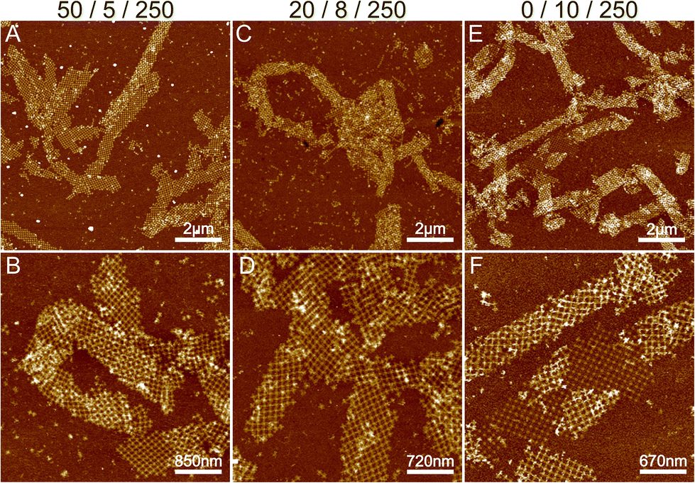 | ||
| Fig. 2 The effect of nickel on lattice formation. (A and B), (C and D) and (E and F) show AFM images of individual ST depositions when the concentrations CMg2+/CNi2+/CNa+ are 50/5/250, 20/8/250 and 0/10/250 mM, respectively. | ||
To conclude, a small amount of Ni2+ (5–10 mM) together with a Na+ concentration of 250 mM seems to endorse the formation of longer and more intact ribbons. To further study this, we fixed Ni2+ and Mg2+ concentrations to 5 mM and 50 mM, respectively (Fig. 2A), and again tested the effect of Na+ concentration on the formation of ribbons (see Fig. 3). Interestingly, there seems to be a certain optimal window in the parameter space, and Na+ concentrations outside this window prevent the formation of ribbons. For the upper limit, the explanation would follow a similar logic as in the Mg–Na deposition, where the high monovalent cation concentration prevents the attraction between the origami. In the case of low Na+ concentrations, the results seem to follow the case of the Mg2+ buffer. Hence, we can draw the following conclusions: the ribbon formation seems to require contributions from both nickel and sodium at moderate salt concentration and by substituting nickel with magnesium one can set the preference between 2D monolayer and 3D double-layered structures.
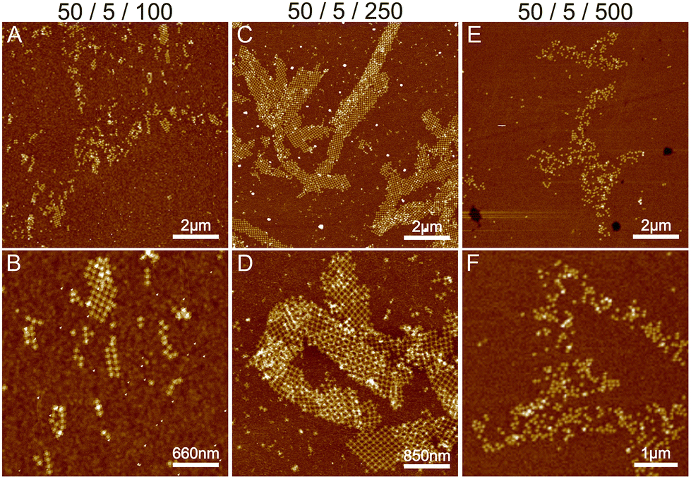 | ||
| Fig. 3 The combined effect of Mg2+, Ni2+ and Na+ on lattice formation. (A and B), (C and D) and (E and F) show AFM images of different ST depositions when the concentrations CMg2+/CNi2+/CNa+ are 50/5/100, 50/5/250 and 50/5/500 mM, respectively. | ||
Based on these findings we made the following hypothesis: the origami starts to assemble hierarchical structures already in solution and the lattice will ultimately fold/bind to itself to form a tube before depositing on the surface. Since the blunt-end stacking is a relatively weak force, in the presence of only Mg2+ and Na+ ions, the origami form only small lattices before unspecifically aggregating when increasing the ion concentrations. Both magnesium and sodium are known to bind with the DNA backbone only, whereas, since Ni2+ interacts also with the bases,43 it especially strengthens the blunt-end stacking, which causes the origami to bind together more strongly and thus form larger assemblies. Since the DNA origami structures in liquid are not usually straight but are at least slightly curved instead, the assemblies can also bend and curve, which can easily lead to rolling them into tubes. On a surface, the flexible tubes naturally collapse and appear as double-layered ribbons with well-defined width in the dry state AFM images.
To confirm this, we imaged the structures in a cryo-TEM and a confocal microscope to find out the topology of the structures in solution (see Fig. 4, S4, S5 and Video S1†). In both cases, we observed tubular or ribbon-like structures. Furthermore, in certain cases, we saw cavities inside the tubes as shown in Fig. 4C, which suggest that the object is indeed a tube. Thus, we can postulate that (i) the ordered structures form in solution and (ii) they have mostly tubular morphology.
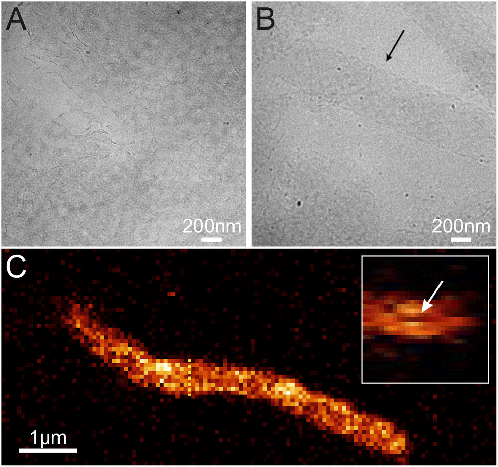 | ||
| Fig. 4 Cryo-TEM and confocal microscope images of different ribbons and tubes. (A) A cryo-TEM image of 2D ribbons, (B) a cryo-TEM image of 3D tubes and (C) a side view confocal microscope image of a 3D tube. The inset in C shows the cross-section highlighted by the yellow dashed line, where a small cavity can be seen inside the tube. The size of the inset is 2 μm × 2 μm. | ||
Based on the AFM images in Fig. 3 and S6† and the confocal images in Fig. 4 and S7,† we characterized the dimensions of the ribbons and tubes (see Fig. 5). As observed before, the length of the ribbons/tubes varies greatly, i.e., between 1 and 5 μm, while their average width is always between 450 and 650 nm. Since the size of the ST is roughly 100 nm, the variation in the average width is of the order of 2 STs. The average width was obtained by measuring it in many places along each ribbon/tube, as shown in Fig. S6† (for R1). We also characterized the uniformity of individual tubes, i.e., the variation of the width along the tube by calculating the standard deviation (SD) for the width in each case. This varied between 10 and 130 nm, and in the AFM images peaked around its mean value at 49 nm, meaning that mostly the tube width varies roughly 50 nm from the average width along the tube. The confocal images showed more random distribution of SDs, but they were still within the same range. The larger variation is explained by the limited resolution of the method. The confocal microscope resolving capability in the x–y direction is about 200 nm at the used wavelength and thus the variation is higher than that with higher-resolution AFM data. Overall, we can say that the tubes are surprisingly uniform in their widths.
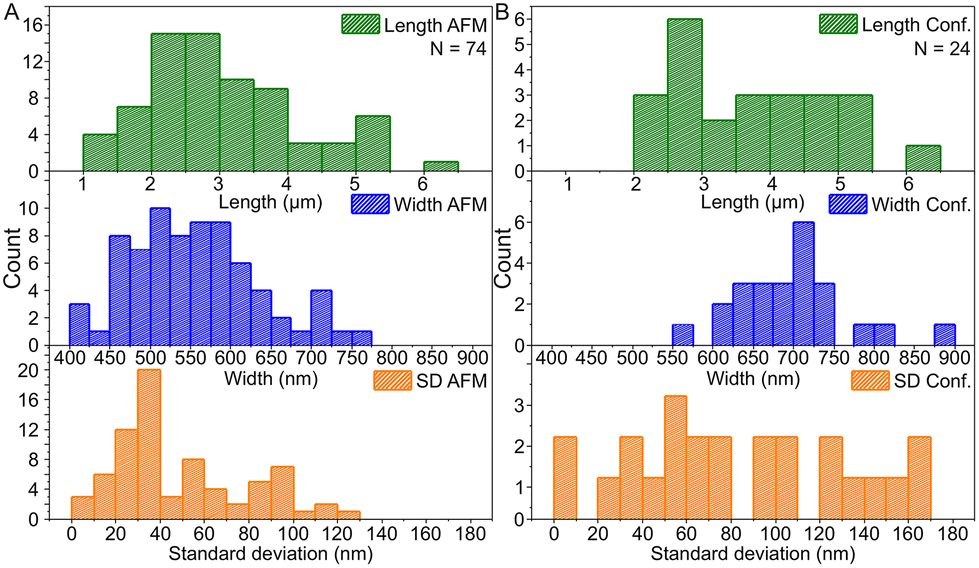 | ||
| Fig. 5 The histogram data of the dimensions of ribbons and tubes. (A) Histograms of the length, the width and the standard deviation of ribbon/tube width based on the AFM data and (B) the same histograms for the confocal microscopy data. N indicates the number of counted ribbons/tubes. | ||
Our theory is that the STs initially form a 2D lattice until the structure can bend and bind to itself along the edges of the ribbon, thus forming a tube as shown in Scheme 1, where further growth can happen in only one direction. This would also explain the uniformity of the width, since the 2D ribbon sheets will all have the same bending properties and thus the same final radius. Besides the tubes, we can also observe stacked double-layered ribbons like those shown in Fig. 2F (lower ribbon). In these cases, most probably only some parts of the ribbon can bend and bind to itself in the presence of Ni2+ ions.
In order to confirm that the main cause for the ribbon/tube formation is the presence of Ni2+ ions and to get an idea about the kinetics of the assembly, we tested if they can be reversibly disassembled by removing all the nickel ions. One of the common reagents to remove divalent ions like Ni2+ is ethylenediaminetetraacetic acid (EDTA).35,36 We utilized dynamic light scattering (DLS) analysis44 combined with AFM imaging and gel electrophoresis to assess the kinetics of the formation and disassembly of the ribbons. In DLS analysis, we first monitored STs in the annealing buffer as a control experiment. After that we prepared a similar ribbon sample as in the case of cryo-TEM and confocal microscopy, and the DLS measurement was started immediately after mixing the buffer with origami. After about 1 h of monitoring the reaction, we removed part of the sample to characterize it with AFM and added EDTA to fix the final concentration in the solution to 40 mM. Immediately after adding EDTA, the reaction was again monitored in DLS for about 1 h and the final sample was characterized in AFM. Similar preparations were done for the gel electrophoresis, where we run plain STs, STs just after the ∼1 h ribbon formation and STs after 1 h of EDTA-induced disassembly of similar ribbons, as above. The results are shown for the DLS in Fig. 6 and Fig. S9,† and in Fig. S10† for the gel electrophoresis.
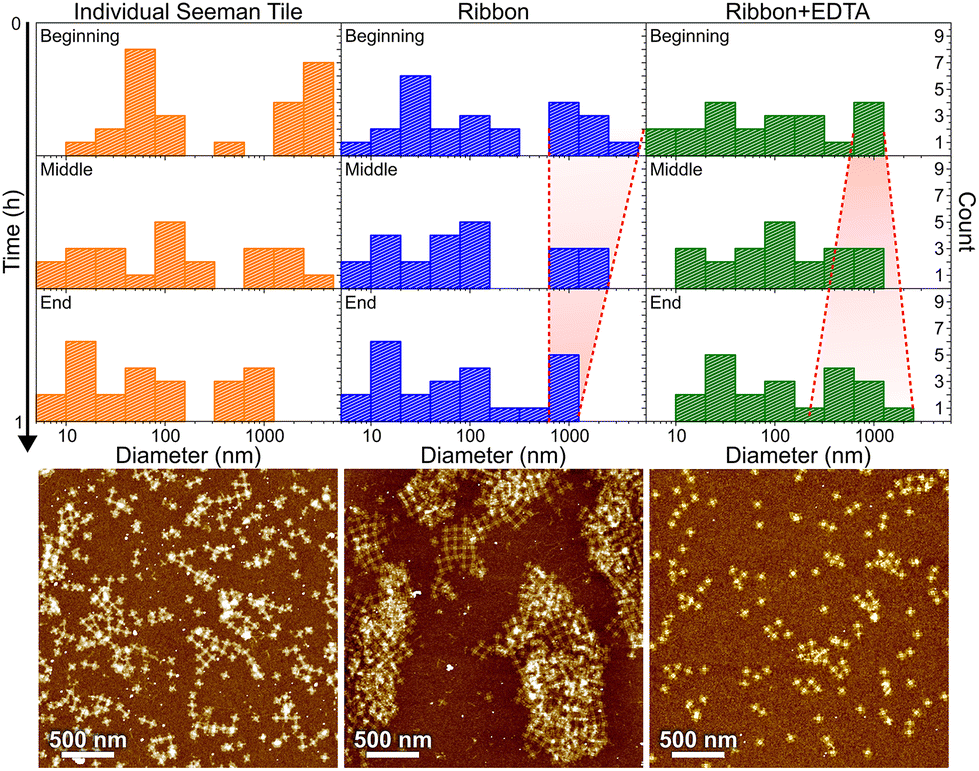 | ||
| Fig. 6 DLS characterization of individual STs, ribbon formation and ribbon disassembly by EDTA, are shown in columns from left to right, respectively. The different rows show statistics along the ∼1 h measurement series in 20 min time steps. The red dashed lines are guides to the eye showing the narrowing (middle column) or widening (right column) of the distribution of large aggregates as a function of time, as discussed in the text. Below each column is an AFM image of the same sample after the incubation. | ||
In Fig. 6, the histograms show the size distributions collected from the DLS data over a 20 min time period. The first row shows the statistics from the first 20 minutes of the total ∼1 h measurement (beginning), middle row within 20–40 min (middle) and the last row within 40–60 min (end). The AFM images below show the sample after each full 1 h step. Since the thin shape of the ST is very unsuitable for the reliable determination of the size by DLS, which is assuming spherical particles, we conclude that the distribution between 10 and 100 nm corresponds to the individual STs, because it remains almost constant between all the measurements and fits the width of the STs, i.e., ∼90 nm. From Fig. 6, it is evident that the plain STs within the annealing buffer also form large aggregates, but their size is not controlled, and they disassemble continuously as indicated by the size distribution varying drastically between 0.3 and 1 μm over time.
During the ribbon formation, i.e., in the presence of Ni2+ ions, the larger aggregates start to assume a more and more uniform size of about 1 μm, visible in the DLS data as a narrowing of the distribution of the larger aggregates. This most probably indicates the formation of controlled shapes, i.e., ribbons and tubes, as is confirmed by the AFM image after the step, shown under the middle column in Fig. 6. This is visible also in the gel electrophoresis as a reduced ST band, because more robust ribbons and tubes do not penetrate much into the gel and are left in the well (see Fig. S10†). In the case of plain STs, the aggregates are formed and deformed continuously and most probably they finally proceed in the gel as individual STs. From the above we can also deduce that the ribbons and tubes are formed in less than an hour, but not much faster. On the other hand, the addition of EDTA breaks the already formed ribbons back into STs and smaller assemblies, and the aggregates start again to have wide variance in their size, as shown by the widening of the distribution (right column in Fig. 6). The AFM imaging after the EDTA treatment indeed reveals only individual STs along the whole surface. This can be also observed in the gel electrophoresis, where the ST band is recovered after incubating ribbons with EDTA, as shown in Fig. S10.†
To summarize, the formation of ribbons is facilitated by the presence of Mg2+, Ni2+ and Na+ ions, where each of these cations interacts differently with the DNA. We characterized the Mg/Ni relationship, where the promotion of the interactions between DNA bases in addition to the backbone resulted in first the formation of the 2D ribbons and subsequently 3D tubes. Similarly, we wanted to test the effect of monovalent cations by substituting Na+ with potassium (K+) ions. Like Na+, K+ is also a monovalent cation, but it is a larger atom/ion than Na+ and it interacts with the DNA bases rather than the backbone.30 In this context, we tested the effect of potassium by substituting Na+ in a similar experiment as shown in Fig. 3C and D (Mg2+/Ni2+/Na+ = 50 mM/5 mM/250 mM) with the same amount of K+ ions, but otherwise performing the deposition process as before. The results are shown in Fig. S8,† where potassium seems to produce punctured or holey ribbons instead of the more intact ribbons that were formed in the presence of Na+ ions. It has been reported that K+ increases the mobility of DNA origami in solution,30 which could be seen as a higher rate of attachment and detachment leading to the formation of punctured structures as shown in Fig. S8.†
Conclusions
The surface deposition and lattice formation process of the blunt-ended Seeman tile (ST) origami in solution was investigated in different buffer conditions. The results revealed that, in the presence of nickel, STs are arranged into elongated, 2D or 3D, micrometer-long ribbons or tubes, with uniform width. In the absence of nickel, the origami form only small, isolated pieces of lattices. It was also observed that increasing the concentration of Ni2+ initially leads to the formation of 2D ribbons and a further increase resulted in 3D tubes. But when the concentration of Ni2+ was increased to above 10 nM, the STs tend to aggregate due to the high overall salt concentration. We hypothesize that the two-way interaction of nickel with both the backbone and the bases plays a key role in the formation of ribbons and tubes by stabilizing the blunt-end stacking between STs:43 as a divalent cation attaching to the bases, nickel could bridge two open base pairs leading to more stable blunt-end stacking. We also tested the effect of potassium as a replacement for sodium, but the samples containing potassium left the ribbons punctured, possibly due to differences in the interaction between the monovalent cation and the DNA origami.In our understanding, the ribbon or tube formation occurs already in the liquid phase and is heavily mediated by the buffer strength. One interesting property is the preferential growth direction of both ribbons and tubes, which had also been earlier observed by Woo et al.39 They attributed this to the twist of the origami, whereas in the twist-corrected version of the origami, a linear chain formation was observed. The twist-corrected version was also employed in the current study and could explain why the ribbons adopt one preferential growth direction. However, the tubes are additionally limited in growth direction by their self-binding scheme, which is also the reason why the observed tubes have a well-defined width.
The length of the tubes and ribbons is less well defined in the experiments. The exact growth mechanism of the tubes and ribbons is not known, and our investigation does not fully explain their formation. However, we could draw parallels between the synthesis of metallic nanorods45,46 and the assembly of DNA origami ribbons/tubes in that both use starting precursors to grow initial small seeds that are then grown larger using the same precursor. In the case of metallic nanorods, one way to control the length of the tube is to adjust the amount of initial seeds and the concentration and generation of the metal ions, i.e., the speed of the growth, so that the seeds grow more uniformly.47 In our case, this could be tested in a future study by making an initial, low-concentration ST solution to form smaller ribbons or tubes and then adding slowly more STs to grow the seeds larger.
The ribbons and tubes present an interesting case where the DNA origami method offers a unique way to induce directional crystal growth. One possible application of the tubes could be in the biomedical field as drug carriers, where multiple different, user-specified biomolecules can be attached inside the tube's cavity via the functionalization of the DNA molecule, or just by geometrical trapping.48,49 However, the stability of the ribbons/tubes in different physiological conditions have not been tested and increasing the stability might be required in in vivo applications. One possible way to achieve this extra stability is to silica coat the structure using previously established methods, which allow the DNA structures to retain their shape in detail.50 Such silica-coated structures could also be further metallized to create microscale plasmonic nanostructures, which could be utilized in nano-optics. Alternatively, tubes can form plasmonic entities by the introduction of metallic nanoparticles along their interiors. Another possible but fully different application for the ribbons/tubes would be in materials science as living building materials (LBMs).51,52
All in all, to the best of our knowledge, this is the first demonstration of blunt-end stacking and mono- and divalent cation-mediated assembly of hierarchical DNA origami structures within solution. This could pave a way for a new liquid assembly, controlled purely by buffer conditions without the need to use ligands or ssDNA. We hypothesize that different micrometer-sized 2D and 3D hierarchical structures could be assembled from arbitrarily shaped DNA origami via blunt-end stacking by altering the buffer conditions.
Author contributions
J.M.P., H.J., K.S., N.M. and K.T. prepared and measured the atomic force microscopy samples. V.R. performed the confocal microscopy characterization. A.K.N. characterized the samples in cryo-TEM. J.M.P. and K.T. carried out the DLS characterization and analysis. J.J.T. conceived the research and coordinated it. J.J.T., M.V.-R., N.M., J.M.P., K.T., K.S. and A.K. contributed to the results analysis, discussion, and interpretation. J.M.P. and K.T. wrote the original draft of the manuscript. The manuscript was written through contributions of all authors. All authors have given approval to the final version of the manuscript.Conflicts of interest
There are no conflicts to declare.Acknowledgements
Funding from the Jane and Aatos Erkko Foundation (J.J.T. and A.K./M.V.-R.) and the Academy of Finland (#330584 and #350797 J.J.T./#308992 A.K. and A.K.N./#330896 M.V.-R.) is gratefully acknowledged. The authors also acknowledge the provision of facilities and technical support by Aalto University at OtaNano – Nanomicroscopy Center (Aalto-NMC).References
- C. Gong, S. Sun, Y. Zhang, L. Sun, Z. Su, A. Wu and G. Wei, Nanoscale, 2019, 11, 4147–4182 RSC.
- P. Wang, T. A. Meyer, V. Pan, P. K. Dutta and Y. Ke, Chem, 2017, 2, 359–382 CAS.
- F. Hong, F. Zhang, Y. Liu and H. Yan, Chem. Rev., 2017, 117, 12584–12640 CrossRef CAS PubMed.
- H.-B. Yao, H.-Y. Fang, X.-H. Wang and S.-H. Yu, Chem. Soc. Rev., 2011, 40, 3764–3785 RSC.
- S. Yang, W. Liu, Y. Zhang and R. Wang, ACS Appl. Mater. Interfaces, 2021, 13, 50516–50523 CrossRef CAS PubMed.
- B. Shen, V. Linko, K. Tapio, S. Pikker, T. Lemma, A. Gopinath, K. V. Gothelf, M. A. Kostiainen and J. J. Toppari, Sci. Adv., 2018, 4(2), aap8978 CrossRef PubMed.
- C. Hamon, S. Nokikov, L. Scarabelli, L. Basabe-Desmonts and L. M. Liz-Marzán, ACS Nano, 2014, 8, 10694–10703 CrossRef CAS PubMed.
- H. Li, Y. Jia, A. Wang, W. Cui, H. Ma, X. Feng and J. Li, Eur. J. Chem., 2014, 20, 499–504 CrossRef CAS PubMed.
- W. Li, Y. Li, Z. Liu, N. Kerdsakundee, M. Zhang, F. Zhang, X. Liu, T. Bauleth-Ramos, W. Lian, E. Mäkilä, M. Kemell, Y. Ding, B. Sarmento, R. Wiwattanapatapee, J. Salonen, H. Zhang, J. T. Hirvonen, D. Liu, X. Deng and H. A. Santos, Biomaterials, 2018, 185, 322–332 CrossRef CAS PubMed.
- S.-W. Cao, Y.-J. Zhu, M.-Y. Ma, L. Li and L. Zhang, J. Phys. Chem. C, 2008, 112, 1851–1856 CrossRef CAS.
- D. Whang, S. Jin, Y. Wu and C. M. Lieber, Nano Lett., 2003, 3, 1255–1259 CrossRef CAS.
- W. Lu and C. M. Lieber, Nat. Mater., 2007, 6, 841–850 CrossRef CAS PubMed.
- J. Ye, R. Weichelt, U. Kemper, V. Gupta, T. A. F. König, A. Eychmüller and R. Seidel, Small, 2020, 16, 2003662 CrossRef CAS PubMed.
- V. M. Shalaev, Nat. Photonics, 2007, 1, 41–48 CrossRef CAS.
- Z. Wang, F. Cheng, T. Winsor and Y. Liu, Nanotechnology, 2016, 27, 412001 CrossRef PubMed.
- K. Sloyan, H. Melkonyan, H. Apostoleris, M. S. Dahlem, M. Chiesa and A. A. Ghaferi, Nanotechnology, 2021, 32, 472004 CrossRef CAS PubMed.
- S. Kasani, K. Curtin and N. Wu, Nanophotonics, 2019, 8, 2065–2089 CrossRef CAS.
- N. Fu, Y. Liu, X. Ma and Z. Chen, J. Microelectron. Manuf., 2019, 2, 19020202 CAS.
- T. Manouras and P. Argitis, Nanomaterials, 2020, 10, 1593 CrossRef CAS PubMed.
- M. Geese and M. Spengler, Mol. Syst. Des. Eng., 2019, 4, 29–48 RSC.
- Z. Fan, J. Yan, L. Zhi, Q. Zhang, T. Wei, J. Feng, M. Zhang, W. Qian and F. Wei, Adv. Mater., 2010, 22, 3723–3728 CrossRef CAS PubMed.
- Q. Zhang, Y. Wang, B. Zhang, K. Zhao, P. He and B. Huang, Carbon, 2018, 127, 449–458 CrossRef CAS.
- N. C. Seeman and H. F. Sleiman, Nat. Rev. Mater., 2018, 3, 17068 CrossRef CAS.
- K. Tapio and I. Bald, Multifunct. Mater., 2020, 3, 032001 CrossRef CAS.
- W. M. Jacobs and D. Frenkel, J. Am. Chem. Soc., 2016, 138, 2457–2467 CrossRef CAS PubMed.
- D. H. Gracias, V. Kavthekar, J. C. Love, K. E. Paul and G. M. Whitesides, Adv. Mater., 2002, 14, 235–238 CrossRef CAS.
- J. Yaun, X. Lu, Q. Li, Z. Lü and Q. Lu, Angew. Chem., Int. Ed., 2021, 60, 12308–12312 CrossRef PubMed.
- K. Tapio, A. Mostafa, Y. Kanehira, A. Suma, A. Dutta and I. Bald, ACS Nano, 2021, 15, 7065–7077 CrossRef CAS PubMed.
- J. M. Parikka, K. Sokołowska, N. Markešević and J. J. Toppari, Molecules, 2021, 26, 1502 CrossRef CAS PubMed.
- Y. Xin, S. M. Rivadeneira, G. Grundmeier, M. Castro and A. Keller, Nano Res., 2020, 13, 3142–3150 CrossRef CAS.
- A. A. Rafat, T. Pirzer, M. B. Scheible, A. Kostina and F. C. Simmel, Angew. Chem., Int. Ed., 2014, 53, 7665–7668 CrossRef PubMed.
- W. Liu, H. Zhong, R. Wang and N. C. Seeman, Angew. Chem., Int. Ed., 2011, 50, 264–267 CrossRef CAS PubMed.
- R. Wang, A. Kuzuya, W. Liua and N. C. Seeman, Chem. Commun., 2010, 46, 4905–4907 RSC.
- S. Elhadj, G. Singh and R. F. Saraf, Langmuir, 2004, 20, 5539–5543 CrossRef CAS PubMed.
- M. B. Johnston, A. J. Bernard Jr. and H. A. Flaschka, J. Chem. Educ., 1958, 35, 601–606 CrossRef CAS.
- C. Kielar, Y. Xin, B. Shen, M. A. Kostiainen, G. Grundmeier, V. Linko and A. Keller, Angew. Chem., Int. Ed., 2018, 57, 9187–9552 CrossRef.
- D. Hayakawa, T. E. Videbaek, D. M. Hall and W. B. Rogers, Proc. Natl. Acad. Sci. U. S. A., 2022, 119, e2207902119 CrossRef CAS PubMed.
- S. Li, Y. Wang, W. Ge, W. Zhang, B. Lu, F. Feng, C. Ni and S.-J. Xiao, Chem. – Eur. J., 2022, 29(3), e202202863 Search PubMed.
- S. Woo and P. W. K. Rothemund, Nat. Commun., 2014, 5, 4889 CrossRef CAS PubMed.
- L. Liu, Y. Li, Y. Wang, J. Zheng and C. Mao, ChemBioChem, 2017, 18, 2404–2407 CrossRef CAS PubMed.
- L. Liu, M. Zheng, Z. Li, Q. Li and C. Mao, ACS Appl. Mater. Interfaces, 2019, 11, 13853–13858 CrossRef CAS PubMed.
- S. Kempter, A. Khmelinskaia, M. T. Strauss, P. Schwille, R. Jungmann, T. Liedl and W. Bae, ACS Nano, 2019, 13, 996–1002 CAS.
- G. Barone, A. Terenzi, A. Lauria, A. M. Almerico, J. M. Leal, N. Busto and B. García, Coord. Chem. Rev., 2013, 257, 2848–2862 CrossRef CAS.
- H. Ijäs, T. Liedl, V. Linko and G. Posnjak, Biophys. J., 2022, 121, 4800–4809 CrossRef PubMed.
- X. Ye, L. Jin, H. Caglayan, J. Chen, G. Xing, C. Zheng, V. Doan-Nguyen, Y. Kang, N. Engheta, C. R. Kagan and C. B. Murray, ACS Nano, 2012, 6, 2804–2817 CrossRef CAS PubMed.
- N. D. Burrows, S. Harvey, F. A. Idesis and C. J. Murphy, Langmuir, 2017, 33, 1891–1907 CrossRef CAS PubMed.
- X. Zhang, N. Tran, T. Egan, B. Sharma and G. Chen, J. Phys. Chem. C, 2021, 125, 13350–13360 CrossRef CAS.
- H. Ijäs, I. Hakaste, B. Shen, M. A. Kostiainen and V. Linko, ACS Nano, 2019, 13, 5959–5967 CrossRef PubMed.
- F. Scheffler, M. Brueckner, J. Ye, R. Seidel and U. Reibetanz, Adv. Funct. Mater., 2019, 29, 1808116 CrossRef.
- M.-K. Nguyen, V. H. Nguyen, A. K. Natarajan, Y. Huang, J. Ryssy, B. Shen and A. Kuzyk, Chem. Mater., 2020, 32, 6657–6665 CrossRef CAS.
- C. M. Heveran, S. L. Williams, J. Qui, J. Artier, M. H. Hubler, S. M. Cook, J. C. Cameron and W. V. Srubar, Matter, 2020, 2, 481–494 CrossRef CAS.
- M. Dade-Robertson, H. Mitrani, J. R. Corral, M. Zhang, L. Hernan, A. Guyet and A. Wipat, Bioinspiration Biomimetics, 2018, 13, 046004 CrossRef PubMed.
- K. Tapio, C. Kielar, J. M. Parikka, A. Keller, H. Järvinen, K. Fahmy and J. J. Toppari, Chem. Mater., 2023, 35(5), 1961–1971 CrossRef CAS.
Footnotes |
| † Electronic supplementary information (ESI) available: Extra AFM, cryo-TEM, and confocal microscopy images of ribbons and tubes; examples of AFM and confocal statistical analysis; cryo-TEM tilting series 3D-video of a tube. See DOI: https://doi.org/10.1039/d2nr06001a |
| ‡ Present address: Microsoft Oy (Suomi), Keilalahdentie 2-4, 02150 Espoo, Finland. |
| § Present address: PiBond Oy, Kutojantie 2, 02630 Espoo, Finland. |
| ¶ Max-Delbrück-Center for Molecular Medicine (Helmholtz Association), Structural Biology Unit, Robert-Rössle-Straße 10, 13092 Berlin, Germany. |
| || Department of Neuroscience and Biomedical Engineering, Aalto University, 00076 Aalto, Finland. |
| This journal is © The Royal Society of Chemistry 2023 |