Motorized, untethered soft robots via 3D printed auxetics†
Pranav
Kaarthik
 a,
Francesco L.
Sanchez
a,
James
Avtges
b and
Ryan L.
Truby
a,
Francesco L.
Sanchez
a,
James
Avtges
b and
Ryan L.
Truby
 *abc
*abc
aDepartment of Mechanical Engineering, Northwestern University, Evanston, IL 60208, USA. E-mail: rtruby@northwestern.edu
bCenter for Robotics and Biosystems, Northwestern University, Evanston, IL 60208, USA
cDepartment of Materials Science and Engineering, Northwestern University, Evanston, IL 60208, USA
First published on 29th August 2022
Abstract
Untethered operation remains a fundamental challenge in soft robotics. Soft robotic actuators are generally unable to produce the forces required for carrying essential power and control hardware on-board. Moreover, current untethered soft robots often have low operating times given soft actuators' limited efficiency and lifetime. Here, we 3D print cylindrical handed shearing auxetics (HSAs) from single-cure polyurethane resins for use as scalable, motorized soft robotic actuators for untethered machines. Mechanical characterization of individual HSAs confirms their auxetic behaviors and suitability as actuators. HSA pairs of opposite handedness are assembled to form multi-degree-of-freedom legs for untethered quadrupeds. We explore several leg designs to understand the role of length and auxetic pattern density on overall motion and blocked force generated. Finally, we demonstrate untethered locomotion with two soft robotic quadrupeds. We find that our taller soft robot is capable of walking at 2 body lengths per min (BL min−1) for 65 min, all while carrying a payload of at least 1.5 kg. We compare our soft robots' capabilities to those of previously reported untethered, terrestrial systems and find that our motorized HSAs lead to the second highest operating time with an above average velocity. We anticipate that these methods will open new avenues for designing untethered soft robots with the robustness, operating times, and payload capacities required for future fundamental investigations in embodied intelligence and adaptive, physical learning.
1 Introduction
Soft robots are physically intelligent machines constructed from soft, deformable materials that enable continuous, bioinspired motions and passive adaptability in unstructured environments. A foundational design decision in soft robotics is actuator selection: it dictates the materials, manufacturing methods, and power requirements needed to realize the final system.1,2 However, the limitations of current soft robotic actuators remain a pressing challenge for the field. In particular, their auxiliary hardware requirements,3–5 poor energy efficiency,6 and relatively low force output7 continue to stymie advances in untethered soft robots capable of long-term operation.8Fluidic, electrostatic, and thermomechanical actuators remain popular in soft robotics.1 Commonly used fluidic actuators require hardware components like pumps, pressurized canisters, and valves for actuation,9,10 whose weight and rigidity pose challenges for untethered performance.11–16 Electrostatic actuators like dielectric elastomer actuators (DEAs) generate rapid, energy-efficient actuation,17 but they require high operating voltages from amplifiers that are non-trivial to miniaturize and integrate in untethered soft robots.18–21 Thermomechanical actuators, like liquid crystal elastomers (LCEs)22 and shape memory alloys (SMAs)4,23,24 that change shape via (Joule) heating, exhibit high actuation forces and high work capacity. However, they display slow reversibility and low energy efficiency. Moreover, each of these actuation strategies presents unique fabrication challenges that often limit them to single degree-of-freedom (DOF) motions like bending, volumetric expansion, or uniaxial contraction. To bypass the shortcomings of soft actuators, many have returned to using conventional motors for actuation.25–29 For example, strategically threaded, motorized tendon cables pull on soft robot bodies to actuate them. Recent work has even used motorized, cable tendon actuation for untethered soft robot walking.30 Still, while tendon-driven actuators are prone to developing slack that decouples body dynamics from motor activity and complicates control, conventional motors – despite their rigidity – stand out as a robust, energy-efficient approach for soft robotic actuation.
More recently, a novel class of deformable architected materials called handed shearing auxetics (HSAs)31 was introduced as an alternative means to motorized soft robotic actuation. Cylindrical HSAs couple rotational and extensional motion in a manner that enables actuation via servo motors.31–33 HSAs were first fabricated by rotary laser cutting extruded tubes of thin-walled Teflon, or polytetrafluoroethylene (PTFE).31,32 The poor reproducibility of rotational laser cutting and limited processability of PTFE tubes motivated the direct manufacturing of HSAs by 3D printing.33 In this early work, HSAs were printed by digital projection lithography (DLP) using expensive industrial printers and proprietary two-part, dual-cure polyurethane resins whose processing requirements limited the overall sizes at which HSAs could be fabricated.33 Overall, HSAs have been exclusively used for soft robotic grippers and tethered demos that use heavy, high-torque servo motors for actuation.31–34
Here, we introduce a strategy for 3D printing HSAs of scalable form factor for untethered soft robot locomotion (Fig. 1). HSAs are 3D printed using a desktop DLP printer and single-cure, polyurethane resins. We demonstrate that the use of single-cure resins with minimal post-processing enables the printing of miniaturized HSAs that maintain their shearing auxetic behavior at decreasing scale.33 We print HSAs for three multi-DOF soft robotic leg designs based on 2 × 2 assemblies of HSAs with opposite handedness, characterizing their range of motion and generated block force. Finally, we demonstrate untethered locomotion in two soft quadrupeds using different leg designs. The HSA legs' high force output enables our soft robot to carry a total payload of up to 1.5 kg, including a microcontroller and lithium ion battery (Fig. 1a). Using a non-optimized gait, we demonstrate a maximum walking speed of 0.031 body lengths per second (BL s−1) and an overall operation time of 65 min.
2 Results and discussion
In this work, we 3D print HSAs from a single-cure polyurethane resin (E-Rigid PU Black, EnvisionTec) for one-step fabrication via DLP (D4K Pro, EnvisionTec, see Fig. 1b, c and Fig. S1, ESI†). This single-cure resin simplifies and expedites HSA fabrication while allowing for miniaturization to new length scales (Fig. 1c). In previous work, using dual-cure polyurethane resins to 3D print HSAs required manual cleaning steps between printing and thermal curing.33 Any residual resin trapped within the printed HSAs' fine features polymerized during the second thermal curing step, constraining the mobility of the HSAs' living hinges that give rise to its shearing auxetic behavior. Therefore, smaller HSA features were difficult to properly print with dual-cure resins, and the overall size scale of printable HSAs was limited. Importantly, previous DLP methods for HSA fabrication involved expensive industrial DLP printers that are not accessible to the broader research community.33The auxetic behavior of HSAs depends on deformable living hinges (or flexure joints) tiled throughout their structure. To accommodate high strain for large shape change, the living hinges should be printed from a photopolymer resin that exhibits a high elongation at break. Their geometry must facilitate large strains as well; living hinges that are too thick will increase effective stiffness, reduce actuation strain, and increase the force required for elongation.31,33 We selected the polyurethane resin for this work largely for its high elongation at break (173%, see Table S1, ESI†). The single-cure polyurethane resin also possesses a shore hardness of D73 and tensile strength of 20.6 MPa. These mechanical properties are comparable to resins previously used to print HSAs.33
When considering HSAs as actuators for untethered soft robots, their size raises important considerations because it dictates the torque needed to actuate them. HSAs' living hinges become thinner as they are scaled to smaller sizes, and the torque required to actuate them decreases with HSA thickness. A servo motor's size and mass generally increase with the maximum output torque it can produce. Thus, HSAs should be scaled such that they can be actuated by servo motors with a minimized mass and footprint. We 3D printed HSAs of various sizes, scaled to 1×, 0.75×, 0.5×, and 0.3× the form of straight HSA designs reported previously33 (Fig. 1c). The geometric parameters of each HSA scaling are provided in Table 1. While HSAs can be printed at scalings between 0.3× and 0.15× (Fig. 1c), removing print supports for HSAs below 0.3× scaling resulted in damage to the part. Printing failed for HSA scalings below 0.15×.
| HSA scale | Length (mm) | Diameter (mm) | Wall thickness (mm) |
|---|---|---|---|
| 1× | 102 | 25 | 1.6 |
| 0.75× | 76 | 19 | 1.2 |
| 0.5× | 51 | 13 | 0.8 |
| 0.3× | 30 | 8 | 0.5 |
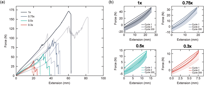
HSAs are mechanically characterized via strain to failure and cyclic extension tests to study their tensile and hysteretic behavior, respectively (Fig. 2 and Fig. S2, ESI†). As HSAs are scaled to smaller sizes, we expect that living hinges of decreasing thickness will bend and facilitate elongation under lower forces. We also anticipate that thinner HSAs will exhibit lower effective stiffness and fail at relatively higher strains. These trends are observed in the force-extension data shown in Fig. 2a, which indicate that the force required to extend an HSA and the strain at failure both decrease with decreasing HSA scaling. We observe that individual hinges or members of the HSA structure begin to fail at higher extensions before ultimate failure (Fig. S3a, ESI†). When we normalize force by HSA thickness and plot versus strain, we qualitatively see that 0.75×, 0.5×, and 0.3× HSAs exhibit similar stiffness and that all HSAs begin to fail around strains of 0.6, regardless of scaling factor (Fig. S3b, ESI†).
Results from cyclic extension tests are shown in Fig. 2b up to 200 cycles. These data reveal the HSAs' viscoelastic behavior, with strain-induced weakening resulting in the hysteresis loops observed for increasing cycle count. Similar viscoelastic behavior in HSAs has been reported previously.33 Table S2 (ESI†) provides the cycle count at which individual members of the HSA structure began to fail and the cycle count of ultimate failure. Individual links in the 0.3× HSAs began to fail before the 200th extension cycle. This did not significantly affect their global mechanical behavior. From these results, it is also likely that slight plastic deformation in the living hinges is contributing to this hysteretic mechanical response. Hysteretic force-extension behavior was observed for HSAs of all scalings and reached a steady-state after approximately 100 cycles in each. Overall, these results demonstrate that our printed HSAs can repeatedly undergo high strains for soft robotic actuation.
Miniaturizing HSAs opens opportunities for directly actuating soft robots with micro servo motors. These servo motors have a reduced physical foot print and low mass, both of which are appealing for designing untethered soft robots whose payloads should be minimized. From the mechanical characterization results and our insights into the printed HSAs' general performance, we selected 0.5× HSAs as the basis for our motorized soft actuators. We reasoned that this scaling would provide successful multi-DOF actuation with lightweight servos, reducing power draw and increasing energy-efficiency for maximum operation time. The thin walls of the 0.3× HSAs presented concerns of the limits on their maximum loading and long-term robustness, while the 0.75× and 1× HSAs qualitatively required torques that surpass those that micro servos can generate.
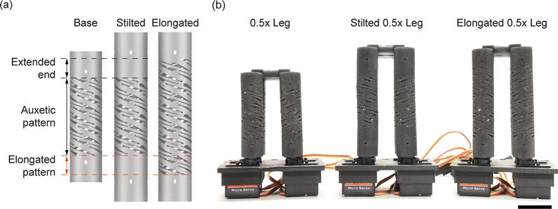
Multi-DOF actuators are readily constructed from HSAs in 2 × 2 configurations in which neighboring HSAs possess an opposite handedness.31–33 Building on this design, we explored three 0.5× HSA assemblies as motorized soft robot legs (Fig. 3 and Fig. S4, ESI†). The three leg designs – 0.5× leg, stilted 0.5× leg, and elongated 0.5× leg (Fig. 3a and b) – allow us to investigate the effect of HSA length and auxetic pattern density on leg performance. The stilted 0.5× legs are similar to the 0.5× legs, except that the ends are extended by elongating the solid ends of the individual HSAs. The elongated 0.5× leg is lengthened by increasing the HSA pattern density along the length of the cylinder. The stilted and elongated 0.5× legs have the same length (Fig. 3a). Each multi-DOF leg weighs 45 ± 1 g (n = 3) and is comprised of four HSAs and four micro servo motors (Power HD 1440A).
As shown in Fig. 4 and Movies S1–S3 (ESI†), the HSA legs are capable of executing various complex motions, including contractile, extending, directional bending, and twisting motions. The servo rotations required to execute each are shown in Fig. 4a, and close-up views of contractile actuation strokes are provided in Fig. S5 (ESI†). In this free displacement context, we qualitatively see that both of the longer HSA legs extend, bend, and twist to a greater extent than the shorter one (Fig. 4b–d). Multi-DOF motions that we demonstrate in the HSA legs have not been achieved in previous untethered soft robots, whose actuators have been limited to simpler, often single-DOF motions.4,12,14,16,19,21,22,30,35–37
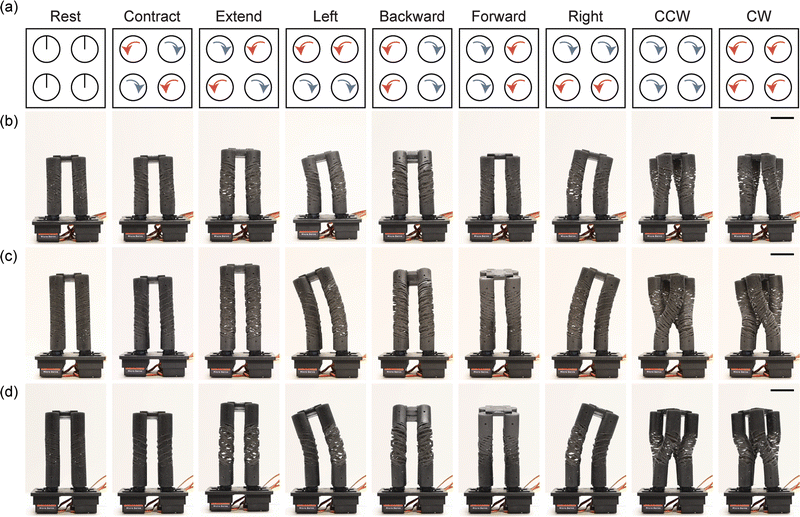 | ||
| Fig. 4 Multi-DOF leg actuation. (a) The servo rotations (to 90°) required to execute a range of linear (contract and extend), bending (left, backward, forward, and right bends), and twisting motions (counter-clockwise (CCW) and clockwise (CW)) are shown. (b–d) The corresponding actuation motifs are shown in the (b) 0.5× leg, (c) extended 0.5× leg, and (d) stilted 0.5× leg. The photographs are stills from Movies S1–S3 in the ESI.† The front two servos as seen on the legs in the photographs correspond to the bottom two servo rotations in (a). Scale bars are 20 mm. | ||
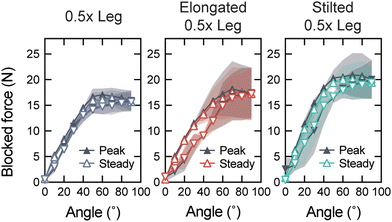
The blocked force generated by each leg design is measured as a function of servo rotation (Fig. 5). The peak blocked force is determined once a servo is rotated to a new angle; the steady blocked force is recorded after a 30 s hold. We observe that the maximum blocked force generated by the 0.5× leg, elongated 0.5× leg, and stilted 0.5× leg are 17.1 ± 1.2 N, 18.2 ± 5.4 N, and 20.9 ± 4.2 N, respectively. Thus, while the elongated legs produce higher blocked forces with the same servo motors, we qualitatively find that the stilted legs are more robust than the elongated leg design. A higher density of the HSA pattern in the elongated 0.5× leg reduces overall leg stiffness and increases the likelihood that the leg will fail at a living hinge after extended operation times. We also observe that the forces generated by the legs are sufficiently high to cause the servo motors to fail themselves before the printed HSAs do. Considering their overall weight (see Table 2), the legs' high force output speaks to their suitability for use in untethered soft robot locomotion.
| Component | Weight (g) |
|---|---|
| HSA leg (×4) | 45–48 (×4) |
| Mounting plate | 40 |
| Top shell | 145 |
| Fasteners (nuts, bolts, washers) | 60 |
| Micro-controller battery | 145 |
| Servo battery | 264 |
| Electronics and wiring | 64 |
| Total | 898–910 |
We constructed two untethered soft robotic quadrupeds using 0.5× legs (Fig. 6a) and stilted 0.5× legs (Fig. 6b). The quadrupeds weigh up to 910 g, with their battery packs representing the largest fraction of their weight (Table 2). Each soft robot is operational with a payload of up to 1.5 kg according to operation tests with additional weights placed onboard.
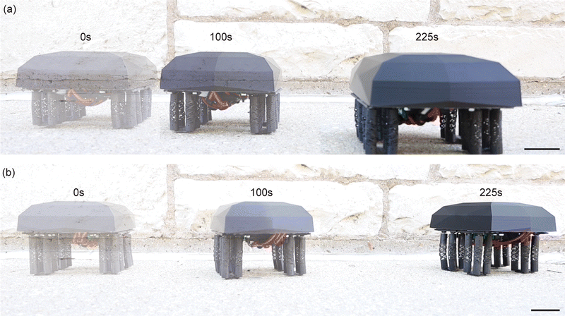 | ||
| Fig. 6 Untethered soft robotic quadrupeds. Untethered HSA-based soft robots constructed with the (a) 0.5× legs and (b) stilted 0.5× legs are shown walking on a concrete sidewalk. Overlays of the quadrupeds are shown at 0 s, 100 s, and 225 s of the walking sequence. Stills are taken from Movie S4 in the ESI.† Scale bars are 50 mm. | ||
The gait for the quadrupeds is developed based on the principles of simultaneous actuation of diagonally opposite legs as seen in nature,38 where the center-of-mass is contained within a bounding polygon formed by the distal ends of the end-effectors to prevent tipping over due to an unsupported center-of-mass.39 The unique challenges of designing and optimizing a gait for these soft robots stem not only from the HSAs' compliance, but from the non-instantaneous and lifespan-variant responses of the HSAs to an applied servo rotation. Determining an appropriate time delay between steps to ensure their full completion is crucial to achieve a smooth gait. For both robots, a uniform time step of 100 ms was satisfactory. Finally, as is always the case with terrestrial locomotion, the contact friction between the legs and the substrate the robot walks on must be balanced to prevent slipping or excessive friction that would prevent the ground reaction forces from driving the robot forward. For untethered locomotion, we designed the gait pattern shown in Fig. 7. For walking in a single direction, we use three actuation modes: extension, contraction, and forward bending.
Fig. 6 shows overlaid stills from video recordings of our two soft robots (see Movie S4, ESI†) walking along a concrete sidewalk using the gait shown in Fig. 7. Here, the bottoms of HSA legs were covered in gaffer tape that provided grip for locomotion. The overlaid stills show the soft robots with the 0.5× legs (Fig. 6a) and stilted 0.5× legs (Fig. 6b) at 0 s, 100 s, and 225 s. We clearly observe a general forward walking in both robots. Since we use the same servo rotation patterns with legs that do not perform identically, the soft robots do not perfectly walk straight forward (e.g., we see the shorter soft robot moving closer towards the camera in Fig. 6a). Still, even on uneven terrain, the soft robots successfully walk with a forward trajectory.
We analyzed the speed and operating time of our soft robots, two important properties for untethered soft robotic systems. On concrete, the shorter and taller soft robots traversed approximately 200 mm and 340 mm in 100 s, respectively. We also studied the robots walking on neoprene rubber sheets using high grit sandpaper on the bottom of their legs. On this softer substrate, the taller soft robot traversed approximately 177 mm in 32 s, while the shorter walked approximately 50 mm in 40 s. Thus, the highest walking speed was measured at 0.031 BL s−1 for the longer legged soft robot walking on the concrete sidewalk. We attribute the taller soft robot's faster walking speed to the larger range of motion its extended legs provide (see Fig. 4b and d). Finally, we measured the soft robot's untethered operating time. The taller soft robot can walk for 65 min with its 6 V 2200 mA h NiMH battery. Given the soft robots' high payload capacity, we expect operating time can be significantly improved with the addition of more battery packs or batteries with a higher capacity.
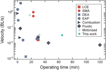
As shown in Fig. 8, we compared the velocity and operating time of our motorized soft robots with those reported for other untethered soft robotic systems4,12,14–16,19,21,22,24,29,30,35–37,40–42 (see Table S3, ESI†). The data points in Fig. 8 also indicate the type of actuation used in each: LCE, SMA, DEA, electroactive polymer (EAP), combustion-powered, fluidic, and motorized. Ideally, untethered soft robots would have high walking speeds and long operating times, but we see that current untethered soft robots are either fast or capable of extended operation – not both. To the best of our knowledge, our taller untethered HSA-based quadruped has the second highest operating time of all untethered soft robots previously reported. One of the first untethered, pneumatically actuated soft robots to be reported has the longest operating time.11 Overall, compared to motorized untethered soft robots, our soft robot's locomotion speed is on par with a reported isoperimetric roller robot.29 A motorized tendon-actuated untethered soft robot30 performed significantly faster, albeit for under a third of the operating time.
3 Conclusions
We present a strategy for developing an untethered soft robot based on 3D printed, motorized auxetic actuators. We extend HSA fabrication to small form factors with a desktop DLP 3D printer and a single-cure polyurethane resin that allows for a reduction of HSA fabrication time and cost. Mechanical characterization of 3D printed HSAs indicates that these actuators exhibit handed shearing auxetic behavior and are appropriate for use as soft robotic actuators. Assemblies of miniaturized HSAs are printed to form multi-DOF legs that we electrically drive with micro servo motors and demonstrate to generate significant force for untethered locomotion. We built two untethered soft robotic quadrupeds using two different leg designs that are capable of walking on uneven surfaces. We demonstrate the second highest operating time reported for untethered, terrestrial soft robots and an above average walking speed. We attribute this to the use of micro servo motors and the ability to carry large payloads (e.g., large batteries) with our printed HSA legs. Moving forward, we see several opportunities for improving the performance of our untethered soft robots. First, higher capacity or additional batteries can be brought onboard to increase operation time. Faster, higher-torque servos could increase walking speed, so long as they maintain suitable energy requirements, size, and mass. Our observations highlight the need to continue optimizing the quadrupeds' gaits as another way to increase walking speed. We expect that improving locomotion will involve utilizing the HSA legs' twisting and off-axis bending modes. Finally, our soft robots' performance can be improved through optimized HSA design (e.g., via topology optimization).Our methods can open opportunities for creating untethered soft robots with long operating times and efficient actuation. Motorizing soft robots built from architected materials like HSAs provides a streamlined path to practically integrating the actuation, control, perception, and power capabilities next-generation soft robots will require.2 We anticipate that future embodiments of the soft robots we present here – which have the payload capacity to bring new sensors,34 cameras, and other hardware on-board – will facilitate new, fundamental experiments with soft machines that are both physically and computationally intelligent.
4 Methods
3D printing HSAs and HSA assemblies
HSAs and HSA pairs are designed and modeled in Rhino 7 (Robert McNeel & Associates) and Solidworks 2021 (Dassault). All HSAs are 3D printed using commercially available E-Rigid PU Black (EnvisionTec), a single-cure polyurethane resin, on a desktop DLP printer (D4K Pro, EnvisionTec). The print orientation and supports are specified on Envision One RP software (EnvisionTec), and HSAs are oriented horizontally on the build platform to optimize support for the structure and reduce fabrication time (Fig. S1, ESI†). The resins are used as received. All parts are cleaned and processed according to the manufacturer's specifications.HSA mechanical characterization
HSAs are mechanically characterized by tensile and cyclic extension tests. HSAs are individually mounted to an Instron tensile testing system via custom 3D printed fixtures (Tough PLA filament, Ultimaker 3) such that one end of the HSA is fixed to the Instron and the other is mounted to a rotational bearing (Grainger) to enable free rotation31 (Fig. S2, ESI†). Before testing, each HSA is pre-cycled 10 times to an actuation strain of 25% at a rate of 10 mm s−1 for the 1× and 0.75× HSAs, and 1 mm s−1 for the 0.5× and 0.3× scale HSAs. For tensile tests, HSAs are elongated to failure at an extension rate of 1 mm s−1. For cyclic extension tests, 1× and 0.75× HSAs are cyclically extended at a rate of 10 mm s−1 for 1000 cycles or until complete HSA failure (see Table S2, ESI†), while 0.5× and 0.3× HSAs are cyclically tested at a rate of 1 mm s−1. The different actuation rates reflect the typical actuation rates in an untethered HSA soft robot.HSA leg assembly and characterization
Each HSA leg is constructed from two HSA pairs. HSA pairs are printed in 2 × 1 configurations consisting of two oppositely handed HSAs. Each free end of the HSA is glued (Gorilla Glue cyanoacrylate adhesive) to individual micro servo motors (Power HD 1440A) via 3D printed adapters that mate the spline of the servo to the inner-diameter of the HSA. The assembled 2 × 2 HSA legs are then fixed to a 3D printed mounting plate (Tough PLA filament, Ultimaker 3).HSA legs are prepared for blocked force testing by first pre-cycling them 10 times between rest and maximum actuation (i.e., at a servo rotation of 90° or −90° depending on the associated HSA's handedness) over a 3 min period. During blocked force testing, an adapter suspends the HSA leg over a digital scale (McMaster Carr) that is in contact with the leg's distal end, or foot (see Fig. S5, ESI†). Each servo is actuated equally, in 10° steps from 0° to 90° to 0°, for a total of 18 steps with a 30 s period between each actuation. This process is performed for 3 different legs per leg design.
Untethered soft robot assembly and operation
The untethered soft robotic quadruped consists of four HSA legs mounted to a custom 3D printed body plate (Tough PLA filament, Ultimaker 3). An Arduino Uno microcontroller controls the walker, and the 16 servos are driven by a PCA9685 servo driver (Adafruit) that communicates with the microcontroller via I2C. The microcontroller and servo driver are housed underneath a custom 3D printed shell (Tough PLA filament, Ultimaker 3). Power is supplied separately to the Arduino Uno and the PCA9685 via a 3S LiPo battery (Zeee Power) and a 6 V NiMH battery pack (Pololu). The LiPo battery and NiMH battery pack are mounted under the shell and underneath the body plate, respectively. The overall dimensions of the walker are 177 mm × 160 mm × 104 mm with the 0.5× HSA legs and 177 mm × 160 mm × 134 mm with both of the elongated leg designs. The gait for the untethered soft robotic walker is programmed in the Arduino IDE (Arduino). The walker is operated on a concrete sidewalk on Northwestern University's campus and a flat, neoprene surface. Operating speeds are determined from video footage of the quadrupeds walking.Comparing untethered soft robot performance
Walking speeds of untethered, terrestrial soft robots are collected from references listed in Table S3, ESI.† Operating times for each are collected and/or estimated from reported data.Author contributions
R. L. T. conceived and supervised the project. P. K. and R. L. T. designed the experiments. P. K., F. L. S., and J. A. performed the experiments, and P. K. analyzed the data. P. K. and R. L. T. wrote the original manuscript draft; all authors contributed to and approve of its final version.Conflicts of interest
There are no conflicts to declare.Acknowledgements
This work was supported by R. L. T.'s faculty start-up funds and the Office of Naval Research (ONR, grant number N00014-22-1-2447).Notes and references
- M. Li, A. Pal, A. Aghakhani, A. Pena-Francesch and M. Sitti, Nat. Rev. Mater., 2022, 7, 235–249 CrossRef PubMed
.
- R. L. Truby, Acc. Mater. Res., 2021, 2, 854–857 CrossRef CAS
.
- M. Wehner, R. L. Truby, D. J. Fitzgerald, B. Mosadegh, G. M. Whitesides, J. A. Lewis and R. J. Wood, Nature, 2016, 536, 451–455 CrossRef CAS PubMed
.
- X. Huang, K. Kumar, M. K. Jawed, A. M. Nasab, Z. Ye, W. Shan and C. Majidi, Sci. Rob., 2018, 3, eaau7557 CrossRef
.
- C. A. Aubin, B. Gorissen, E. Milana, P. R. Buskohl, N. Lazarus, G. A. Slipher, C. Keplinger, J. Bongard, F. Iida, J. A. Lewis and R. F. Shepherd, Nature, 2022, 602, 393–402 CrossRef CAS
.
- L. Shui, L. Zhu, Z. Yang, Y. Liu and X. Chen, Soft Matter, 2017, 13, 8223–8233 RSC
.
- S. M. Mirvakili and I. W. Hunter, Adv. Mater., 2017, 30, 1704407 CrossRef PubMed
.
- S. I. Rich, R. J. Wood and C. Majidi, Nat. Electron., 2018, 1, 102–112 CrossRef
.
- M. Wehner, M. T. Tolley, Y. Mengüç, Y.-L. Park, A. Mozeika, Y. Ding, C. Onal, R. F. Shepherd, G. M. Whitesides and R. J. Wood, Soft Rob., 2014, 1, 263–274 CrossRef
.
- G. M. Whitesides, Angew. Chem., Int. Ed., 2018, 57, 4258–4273 CrossRef CAS PubMed
.
-
M. T. Tolley, R. F. Shepherd, M. Karpelson, N. W. Bartlett, K. C. Galloway, M. Wehner, R. Nunes, G. M. Whitesides and R. J. Wood, IEEE/RSJ Int. Conf. Intell. Robots Syst., 2014, pp. 561–566 Search PubMed
.
- M. T. Tolley, R. F. Shepherd, B. Mosadegh, K. C. Galloway, M. Wehner, M. Karpelson, R. J. Wood and G. M. Whitesides, Soft Rob., 2014, 1, 213–223 CrossRef
.
-
D. Drotman, S. Jadhav, M. Karimi, P. Dezonia and M. T. Tolley, IEEE Int. Conf. Robot. Autom., 2017, pp. 5532–5538 Search PubMed
.
- A. Rafsanjani, Y. Zhang, B. Liu, S. M. Rubinstein and K. Bertoldi, Sci. Rob., 2018, 3, eaar7555 CrossRef
.
-
T. Duggan, L. Horowitz, A. Ulug, E. Baker and K. Petersen, IEEE Int. Conf. Soft Robot., 2019, pp. 200–205 Search PubMed
.
- S. Li, S. A. Awale, K. E. Bacher, T. J. Buchner, C. Della Santina, R. J. Wood and D. Rus, Soft Rob., 2022, 9, 324–336 CrossRef PubMed
.
- Y. Guo, L. Liu, Y. Liu and J. Leng, Adv. Intell. Syst., 2021, 3, 2000282 CrossRef
.
- T. Li, G. Li, Y. Liang, T. Cheng, J. Dai, X. Yang, B. Liu, Z. Zeng, Z. Huang, Y. Luo, T. Xie and W. Yang, Sci. Adv., 2017, e1602045 CrossRef PubMed
.
-
J. Cao, L. Qin, H. P. Lee and J. Zhu, Electroactive Polymer Actuators and Devices (EAPAD), 2017, pp. 322–328 Search PubMed
.
- J. Cao, L. Qin, J. Liu, Q. Ren, C. C. Foo, H. Wang, H. P. Lee and J. Zhu, Extreme Mech. Lett., 2018, 21, 9–16 CrossRef
.
- X. Ji, X. Liu, V. Cacucciolo, M. Imboden, Y. Civet, A. El Haitami, S. Cantin, Y. Perriard and H. Shea, Sci. Rob., 2019, 4, eaaz6451 CrossRef PubMed
.
- Q. He, Z. Wang, Y. Wang, A. Minori, M. T. Tolley and S. Cai, Sci. Adv., 2019, 5, eaax5746 CrossRef CAS PubMed
.
- H.-T. Lin, G. G. Leisk and B. Trimmer, Bioinspiration Biomimetics, 2011, 6, 026007 CrossRef PubMed
.
- X. Huang, K. Kumar, M. K. Jawed, A. Mohammadi Nasab, Z. Ye, W. Shan and C. Majidi, Adv. Mater. Technol., 2019, 4, 1800540 CrossRef
.
- B. Mazzolai, L. Margheri, M. Cianchetti, P. Dario and C. Laschi, Bioinspiration Biomimetics, 2012, 7, 025005 CrossRef CAS PubMed
.
-
J. M. Bern, G. Kumagai and S. Coros, IEEE/RSJ Int. Conf. Intell. Robots Syst., 2017, pp. 3739–3746 Search PubMed
.
- K. W. O'Brien, P. A. Xu, D. J. Levine, C. A. Aubin, H.-J. Yang, M. F. Xiao, L. W. Wiesner and R. F. Shepherd, Sci. Rob., 2018, 3, eaau5543 CrossRef PubMed
.
-
J. Barreiros, K. W. O'Brien, S. Hong, M. F. Xiao, H.-J. Yang and R. F. Shepherd, IEEE Int. Conf. Soft Robot., 2019 Search PubMed
.
- N. S. Usevitch, Z. M. Hammond, M. Schwager, A. M. Okamura, E. W. Hawkes and S. Follmer, Sci. Rob., 2020, 5, eaaz0492 CrossRef
.
-
S. Gong, J. Wu, T. Zheng, W.-M. Zhang and L. Shao, 27th International Conference on Mechatronics and Machine Vision in Practice (M2VIP), 2021, pp. 417–422 Search PubMed
.
- J. I. Lipton, R. MacCurdy, Z. Manchester, L. Chin, D. Cellucci and D. Rus, Science, 2018, 360, 632–635 CrossRef CAS PubMed
.
-
L. Chin, J. Lipton, R. MacCurdy, J. Romanishin, C. Sharma and D. Rus, IEEE Int. Conf. Soft Robot., 2018 Search PubMed
.
- R. L. Truby, L. Chin and D. Rus, IEEE Robot. Autom. Lett., 2021, 6, 795–802 Search PubMed
.
- R. L. Truby, L. Chin, A. Zhang and D. Rus, Sci. Adv., 2022, 8, eabq4385 CrossRef PubMed
.
- N. W. Bartlett, M. T. Tolley, J. T. B. Overvelde, J. C. Weaver, B. Mosadegh, K. Bertoldi, G. M. Whitesides and R. J. Wood, Science, 2015, 161–165 CrossRef CAS PubMed
.
- D. Drotman, S. Jadhav, D. Sharp, C. Chan and M. T. Tolley, Sci. Rob., 2021, 6, eaay2627 CrossRef
.
- X. Yang, L. Chang and N. O. Pérez-Arancibia, Sci. Rob., 2020, 5, eaba0015 CrossRef PubMed
.
- C. S. Mendes, I. Bartos, Z. Márka, T. Akay, S. Márka and R. S. Mann, BMC Biol., 2015, 13, 1–11 CrossRef PubMed
.
- M. Calisti, G. Picardi and C. Laschi, J. R. Soc., Interface, 2017, 14, 20170101 CrossRef
.
- B. Goldberg, R. Zufferey, N. Doshi, E. F. Helbling, G. Whittredge, M. Kovac and R. J. Wood, IEEE Robot. Autom. Lett., 2018, 3, 987–993 Search PubMed
.
- I. Must, F. Kaasik, I. Põldsalu, L. Mihkels, U. Johanson, A. Punning and A. Aabloo, Adv. Eng. Mater., 2015, 17, 84–94 CrossRef CAS
.
-
M. Qi, Y. Zhu, Z. Liu, X. Zhang, X. Yan and L. Lin, Proc. IEEE Int. Conf. Micro Electro Mech. Syst., 2017, pp. 761–764 Search PubMed
.
Footnote |
| † Electronic supplementary information (ESI) available. See DOI: https://doi.org/10.1039/d2sm00779g |
| This journal is © The Royal Society of Chemistry 2022 |


