
 Open Access Article
 This Open Access Article is licensed under a
 Creative Commons Attribution 3.0 Unported Licence
3D printing of soft fluidic actuators with graded porosity†
Nick
Willemstein
,
Herman
van der Kooij
 and
Ali
Sadeghi
*
and
Ali
Sadeghi
*
Department of Biomechanical Engineering, University of Twente, 7500AE, Enschede, The Netherlands. E-mail: a.sadeghi@utwente.nl
First published on 22nd August 2022
Abstract
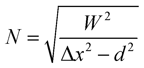
New additive manufacturing methods are needed to realize more complex soft robots. One example is soft fluidic robotics, which exploits fluidic power and stiffness gradients. Porous structures are an interesting type for this approach, as they are flexible and allow for fluid transport. In this work, the infill foam (InFoam) method is proposed to print structures with graded porosity by liquid rope coiling (LRC). By exploiting LRC, the InFoam method could exploit the repeatable coiling patterns to print structures. To this end, only the characterization of the relationship between nozzle height and coil radius and the extruded length was necessary (at a fixed temperature). Then by adjusting the nozzle height and/or extrusion speed the porosity of the printed structure could be set. The InFoam method was demonstrated by printing porous structures using styrene–ethylene–butylene–styrene (SEBS) with porosities ranging from 46% to 89%. In compression tests, the cubes showed large changes in compression modulus (more than 200 times), density (−89% compared to bulk), and energy dissipation. The InFoam method combined coiling and normal plotting to realize a large range of porosity gradients. This grading was exploited to realize rectangular structures with varying deformation patterns, which included twisting, contraction, and bending. Furthermore, the InFoam method was shown to be capable of programming the behavior of bending actuators by varying the porosity. Both the output force and stroke showed correlations similar to those of the cubes. Thus, the InFoam method can fabricate and program the mechanical behavior of a soft fluidic (porous) actuator by grading porosity.
1 Introduction
Soft robotics utilizes softness and smart design to realize robots that are inherently safe for human–robot interaction and compliant to unforeseen disturbances. Soft fluidic robotics is among the most popular types due to its flexibility, wide range of applications, and (relative) simplicity for actuation. It has been used in a broad range of applications from grippers1 to autonomous systems.2Soft fluidic robotics works by transferring fluidic power (flow and pressure) from one place to another. This power can be used for actuation,1 sensing,3 and control.2,4 Soft fluidic actuators (SFAs) consist of mechanically compliant chambers that can be deformed using fluidic power. The deformation of these chambers is defined by the stiffness gradient of the structure. This gradient allows for motions such as translation, bending, and twisting.5 Researchers employ a broad number of methods to realize this stiffness gradient, which include exploiting material properties and/or geometry. An approach is to add a second material such as fibers5 textile,1 and/or paper6 in a dedicated geometry. Other approaches use a single material and exploit geometrical features, such as origami7 and kirigami.8 A prominent example of exploiting internal geometry is porous structures, such as foam.
An advantage of porous structures is that they can, inherently, allow for fluidic transport and are flexible. In addition, porous structures are compressible. This feature has been exploited to realize vacuum-driven actuators. Examples thereof include a continuum soft robot,9 high-force sensorized foam actuators,10 and bending actuators.11 Lastly, positive pressure actuation is also feasible with porous structures for both actuation12 and control.13
Existing methods for fabricating porous structures span a broad spectrum of approaches. A popular approach is to use commercial foams combined with semi-automatic/manual processing, such as laser-cutting, gluing, and coating with silicone or lamination (for airtightness).9,10,14 Another method is to use casting with a sacrificial scaffold/material such as salt,12,13 sugar15 or polyvinyl alcohol (PVA)16 that can be removed afterwards.
To realize the multifunctional nature of soft robotic systems (including SFAs based on porous structures), additive manufacturing (AM) is considered a promising fabrication method. The literature has already demonstrated that AM can realize (sensorized) SFAs.17–21 However, the fabrication of porous structures for soft robots by AM methods is less developed.
Recently, a custom ink22 for realizing local porosity was developed by adding a porogen. By regulating the ratio of ammonium bicarbonate (the porogen) and silicone rubber the porosity can be changed locally. This approach requires modification of the material itself.
Besides using a chemical reaction, a porous structure can also be realized by the fabrication of miniature patterns during the AM process. Liquid rope coiling (LRC) is an interesting candidate for the fabrication of these patterns. LRC is the coiling of a viscous fluid, such as honey, due to buckling when falling from an elevated height.23
LRC has already been exploited to fabricate porous structures.24–28 Results in the literature indicate that LRC can realize stiffness changes of more than one order of magnitude.24,28 In addition, it has been shown to be feasible to print different patterns by proper selection of process parameters.25,26,28 Such an approach has been applied to AM processes to extrude molten materials that solidify in the process, such as glass25 and thermoplastics.27,28 Although these initial results indicate that porous structures can be realized with LRC and AM, its application to soft robotics has, to the knowledge of the authors, not yet been explored. In addition, we also explore how to use LRC to create multiple levels of porosity in a single structure to realize mechanical programming with porosity. In this work, a new printing approach that exploits LRC for the fabrication of porous structures using hyperelastic materials is proposed. This new approach is referred to as the infill foam (InFoam) approach. We demonstrate how the coiling behavior of LRC can be incorporated into the fused deposition modeling (FDM) process to fabricate porous hyperelastic structures. To use hyperelastic materials within the FDM process a screw extruder (see Fig. 1(a)) was used.20,29 Subsequently, the InFoam method is used for mechanical programming of stiffness, density, and energy dissipation. Then the extension to graded porosity is demonstrated as a tool for programming the deformation and to program the behavior of soft bending vacuum actuators.
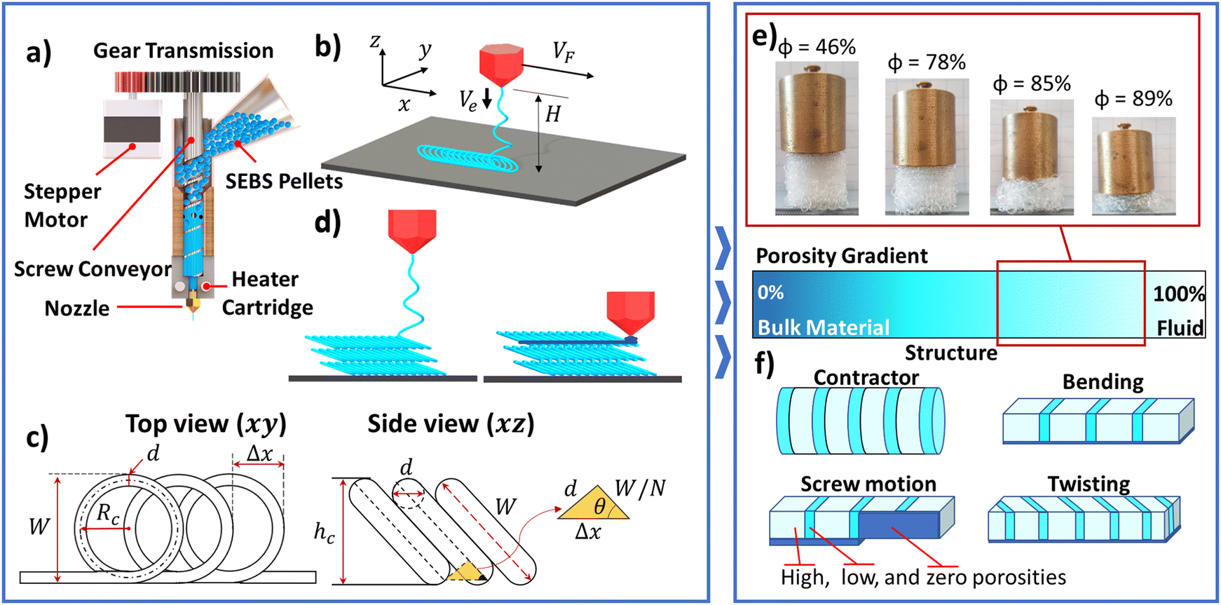 | ||
| Fig. 1 (a) Screw extruder, (b) liquid rope coiling setup with important parameters, (c) coil geometry, (d) grading approach, (e) cubes with different porosities under the same load, and (f) porosity gradients for soft vacuum actuators. | ||
2 Materials and methods
2.1 From coiling to printing
Liquid rope coiling is a phenomenon that can be observed when extruding a viscous liquid above the printing surface (see Fig. 1(b)). This situation is also observed in extrusion-based AM methods such as FDM. When there is a gap between the nozzle and printing surface, the deposited material acts as a flexible (liquid) rope that buckles, which leads to a pattern of coils on the surface (see Fig. 1(b)). A wide variety of shapes can be achieved through LRC, such as a meander and figure of eight.30,31 In this work, the focus is purely on the circular coil pattern. The repetitive nature of the circular coiling pattern makes it an interesting tool for 3D printing.The literature has shown that the shape of the deposited coils (called the coiling pattern) depends on three parameters, namely (I) the viscosity of the extruded material, (II) the height (H) of the nozzle above the platform, and (III) the ratio of extrusion (Ve) and printhead speed (VF).30,32 All three parameters can be set by the user in the FDM process. The viscosity can (primarily) be set using the printing temperature and height by moving the nozzle, whereas the ratio of extrusion and printhead speed is set by the extrusion multiplier (α). The variable α is the screw rotation (in radians) per millimeter moved of the nozzle. In essence, α scales the distance traveled by the printhead to compute the required screw rotation, which defines the ratio of speeds.
These parameters can be set to control the coiling pattern and to plan the desired shape. However, modeling the coiling pattern is not straightforward due to the changes in material properties (such as viscosity) due to the solidification of the thermoplastic during deposition. In this work, an experimental method, similar to that in ref. 25, is used to characterize the coiling pattern.
Similar to conventional printing, the InFoam method needs the dimensions (width and height) of the coiling pattern for path planning. The coiling pattern consists of coils that stack on top of each other in line with the movement of the printhead (see Fig. 1(b)). The geometry of this coiling pattern can be used to compute the width and height. As can be observed from Fig. 1(c), the width W of the coiling pattern is equal to the diameter of the coil, which is equal to
| W = 2Rc + d | (1) |
 | (2) |
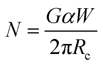 | (3) |
The coil density and radius can be used to compute the coil height hc. The coil can be modelled as a rectangle with rounded corners (see Fig. 1(c)) under an angle of 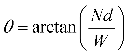 . The height is then equal to
hc = W![[thin space (1/6-em)]](https://www.rsc.org/images/entities/i_char_2009.gif) sin(θ) + (1 − sin(θ))d sin(θ) + (1 − sin(θ))d | (4) |
The preceding equations can be used for path planning and characterization of the coiling pattern. Specifically, eqn (1) and (4) can be used to compute the width and height of the coiling pattern, whereas eqn (2) and (3) can be used to measure and set the desired coil density (N-value), respectively. To use these equations the value of Rc needs to be characterized to relate it to H. The geometry of the deposited coiling patterns will introduce porosity. This porosity can be used for mechanical programming of a structure.34 The possibility of grading the porosity allows for localized mechanical programming. Combining LRC and the normal plotting of the 3D printer enables such functionality by using the deposited coils as a scaffold for the normal plotting. A solution for printing non-porous zones is to move the nozzle down after extruding a layer of coils (i.e. the scaffold) and then locally plot the additional material (see Fig. 1(d)). This simple approach enables porosity grading and ensures proper force transfer by welding layers of coils together.
2.2 Mechanical programming with porosity
The InFoam method can produce (graded) coiling patterns with different coiling radii and N-values by adjusting the extrusion multiplier (α) and/or the height (H). The realized coiling patterns can be used to print porous structures. The porosity will have a major influence on the resulting mechanical properties.34 The repetitive nature of the coiling pattern was exploited to estimate the porosity ϕ (in percent), which is equal to (see the ESI† for the derivation)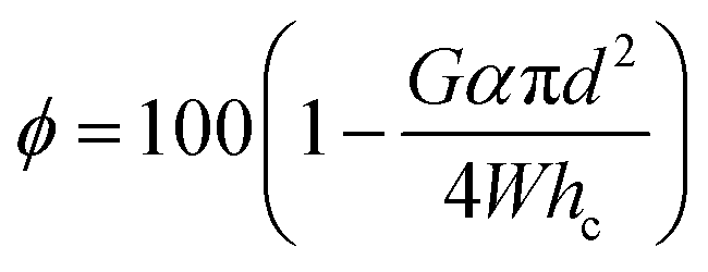 | (5) |
The porosity can be used to program a wide variety of mechanical properties, which include elastic modulus and density. The elastic modulus decreases quadratically with the porosity.34 The large change in stiffness is visualized by the samples shown in Fig. 1(e) wherein the same load leads to deformations ranging from minor (ϕ = 46%) to large (89%).
In general, the effect of porosity on the mechanical properties can be captured in a power-law relationship through the phenomenological model:34
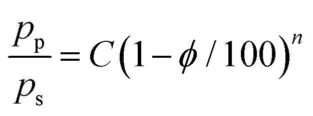 | (6) |
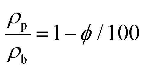 | (7) |
Based on the capability of porosity for mechanical programming it is interesting to estimate the range of porosities that the InFoam method can provide through LRC. Eqn (5) can be rewritten using eqn (3) to express the porosity purely as coil geometry to get
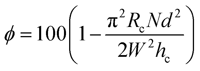 | (8) |
 | (9) |
 | (10) |
Lastly, the theoretical porosity gradient can be determined based on the coil geometry. Changing either the coil density and/or radius requires changing the extrusion rate and/or height, respectively. However, either change will always be limited by the geometry of the coiling pattern, which means the distance between successive coils in plane (Δx) and the coil height (hc) out-of-plane. A higher resolution can be achieved by using the plotting method (Fig. 1(d)), as it is not limited by the geometry of the coiling pattern.
2.3 Experimental setup and methodology
![[thin space (1/6-em)]](https://www.rsc.org/images/entities/char_2009.gif) :63 gear ratio between the stepper motor and screw was added. However, the extrusion multiplier (α) will always refer to the rotation of the screw. As the printing material G1657 styrene–ethylene–butylene–styrene (SEBS) pellets (Kraton Corporation, USA) with a Shore hardness of 47A and a bulk density of 900 kg m−3 were used. In addition, all experiments were conducted with a printing temperature of 230 °C and a nozzle diameter of d = 0.4 mm. Lastly, the G-code for printing with the InFoam method was generated using a custom script in MATLAB (MathWorks, Inc., USA). Printing with the InFoam method is shown in Movies 1 in the ESI.†
:63 gear ratio between the stepper motor and screw was added. However, the extrusion multiplier (α) will always refer to the rotation of the screw. As the printing material G1657 styrene–ethylene–butylene–styrene (SEBS) pellets (Kraton Corporation, USA) with a Shore hardness of 47A and a bulk density of 900 kg m−3 were used. In addition, all experiments were conducted with a printing temperature of 230 °C and a nozzle diameter of d = 0.4 mm. Lastly, the G-code for printing with the InFoam method was generated using a custom script in MATLAB (MathWorks, Inc., USA). Printing with the InFoam method is shown in Movies 1 in the ESI.†
For this characterization, several lines were printed. Afterwards, the printed lines were scanned with a USB camera, and the acquired images were analyzed using ImageJ.35 To relate the pixel distance to real-world distances dots on the printbed were used as a reference distance. Specifically, the width (W) and linear distance (Δx) were measured. These measurements were used to determine Rc and the N-value using eqn (1) and (2), respectively.
After printing the cubes, the mass and height were measured using a scale and caliper, respectively. The resulting porosity was then computed using the measured density by dividing the mass by the volume of the cube. The resulting porosity (in percent) is then computed using eqn (7).
Subsequently, the stiffness and damping were investigated using a universal tensile tester (Instron 3343, Instron, USA). The testing was done in four phases. Firstly, the cubes were pre-loaded by compressing to 5 mm (engineering strain of 0.2 mm mm−1) at a speed of 5 mm min−1 (engineering strain rate of 1/300 s−1). Secondly, it returned to its original position at 60 mm min−1 (1/25 s−1). These two load steps were performed to have a similar pre-load for all cubes. After pre-loading both slow compression (10 mm min−1 or an engineering strain rate of 1/150 s−1) and fast decompression (60 mm min−1 or 1/25 s−1) were performed. The slow compression load step compressed the cube for 21 mm (a strain of 0.84 mm mm−1). This loading step was slow to have a primarily elastic response. Lastly, the tensile tester returned to its original position with a speed of 60 mm min−1. The speed was higher in this step to increase the viscous damping component. These loading steps were performed for all three axes (each in triplicate).
The stiffness was approximated by computing the segment modulus of compression at different levels of strain. A quadratic curve was fitted at specific levels of strain using the twelve preceding data points. These data points were acquired at a sampling time of 0.1 s and a strain rate of 1/150 s−1. This condition meant that the segment modulus of compression was computed by fitting a curve over a strain of 0.008 mm mm−1 and taking its slope. In addition, the dissipated energy by hysteresis was investigated to evaluate the damping. The dissipated energy was computed by taking the ratio of the stress–strain curve's inner shape (i.e. between the forward and backward motions) and the overall curve. This approach computes the energy dissipation relative to the total energy.
The bending actuators with spacers were further investigated to characterize the effect of porosity on the output force and stroke. To this end, four soft bending actuators were printed with different levels of high porosity (ϕ = [77.6, 79.1, 83.8, 85.2]). In contrast, the low porosity spacer was kept the same for all (15%). The nominal dimensions of these actuators were 15 mm width, 75 mm length and 8 mm height. These actuators used a zero porosity strip as a (relatively) stiff substrate (1 mm thick). Subsequently, the actuators were put in a heat-sealed SEBS sleeve (0.4 mm thick). Both the sleeves and actuators were fabricated in triplicate. The setup used for characterization of the output force and stroke evaluation is shown in Fig. 2. The swing acts as a grasping object with a bearing to reduce friction. An LSB200 load cell (Futek, USA) was integrated into the swing to measure the output force, which was connected to an Arduino Uno (Arduino AG, Italy) through an HX711 load cell amplifier (Avia Semiconductor, China). The load cell was tared right before starting a measurement to offset the mass of the actuator. For actuation, a vacuum source was operated using a manually triggered valve, and the vacuum pressure was set using a flow valve. The pressure was read by the Arduino Uno using an MXP5011DP pressure sensor (NXP Semiconductors, The Netherlands). The Arduino and a USB webcam (to record the deformation of the actuator) were connected through a USB to MATLAB. This experiment was performed in triplicate for each actuator for 30 seconds.
 | ||
| Fig. 2 Actuator characterization setup. | ||
For analysis of the data, a Maxwell viscoelastic model36 with one term was fitted to the force data, which is defined as
| F(t) = (K0 + K1exp(−t/τ1))Fmax | (11) |
exp(−ts/τ1)).
In addition, the bending actuators were characterized in terms of stroke using the same setup. For these experiments (repeated thrice), the swing was removed and the actuator was pressurized. Afterwards, the captured images were used to compute the stroke. Specifically, MATLAB was used to fit a circle along the deformed structure using three points to compute the maximum curvature.
Lastly, one printed bending actuator per level of porosity was subjected to a fatigue test. In this fatigue test, the actuators were pressurized (50 kPa, 1.5 seconds) and depressurized (atmosphere, 1.5 seconds) for 1500 cycles in the setup shown in Fig. 2. The pressure cycling was regulated using an Arduino Uno that controlled a solenoid valve using on/off control with the pressure measured using the aforementioned MXP5011DP pressure sensor. After the first and then every 500 cycles the actuator was characterized for its stroke without the swing (at 50 kPa). In contrast, the output force was computed by taking the minimum and maximum peaks per cycle. The aforementioned HX711 load cell amplifier was used to measure the output force.
3 Results and discussion
3.1 Characterization of coiling pattern
The effect of the height (H) on the coil radius (Rc) is shown in Fig. 3(a). The plotted values of Rc are plotted for multiple values of screw rotational speed (αVf with Vf being the printhead speed) at the same height. It can be observed that Rc is linearly related to the height (H) in the range of 2.5 mm to 15 mm, with almost one order of magnitude of increase. In contrast, the increase of Rc seems to stall between 15 and 20 mm. This stalling implies that increasing H will no longer increase Rc (and could even decrease).32 This behavior makes further increasing the height not interesting for the InFoam method as it does not allow for larger coils. In addition, it further cools down the thermoplastic, which can lead to bonding issues making it even less appealing. | ||
| Fig. 3 (a and b) Coil radius versus height H (a) and (b) rotational speed of screw (αVF), and (c) the coil density (N-value) versus coil density multiplier (αW(2πRc)) used to estimate G (see eqn (3)). | ||
Besides H, the literature indicates that Rc decreases when the viscosity decreases.32 Due to the shear-thinning behavior of the thermoplastic, a decrease in viscosity (for constant temperature) should therefore coincide with an increased extrusion speed. The extrusion speed is equivalent (under the assumption of linearity) to an increased rotational speed of the screw αVF, which is plotted against Rc in Fig. 3(b). It can be observed that there is a nonlinear and downwards trend with increasing extrusion speed. This behavior is in line with a power-law shear-thinning relationship. To compare the shear-thinning behavior, the viscosity of the SEBS material was first measured using a Rheocompass MC501 (Anton Paar GmbH, Germany) with the data shown in Fig. S2 of the ESI.† The data were then fitted to a power-law normalized by Rc (using the exponent of the viscosity (n − 1 = −0.09), average coil radius ![[R with combining circumflex]](https://www.rsc.org/images/entities/i_char_0052_0302.gif) c per H, and the rotational speed of the screw αVF):
c per H, and the rotational speed of the screw αVF):
| Rc = a(αVF)n−1c | (12) |
The N-value is plotted against the coil density multiplier αW/(2πRc) (see eqn (3)) in Fig. 3(c) (using the mean value of Rc per H). It can be observed that there is indeed a linear relationship for the N-value. The linearity is also observed by fitting a line with G = 0.17 mm mrad−1 (eqn (3)). The accuracy thereof implies that the proposed relationship is valid. In addition, when extruding in the air the value of G was found to be in the range of 0.154–0.165 mm mrad−1, which is in the same range as the fitted value (see the ESI†). Lastly, it can be observed that lower H values do not achieve high N-values. This discrepancy is due to the coils stacking up too much. When this occurs the coiling pattern is replaced with an accumulation of material.31 This accumulation phase is more chaotic and not used in the InFoam method.
In addition, the coil height (hc) estimation (eqn (4)) was validated using the coiling patterns to be on average within 4% (see the ESI†).
Lastly, the complexities of the solidification and viscoelastic behavior during deposition make it challenging to generalize the coiling patterns to other temperatures and/or materials. The modelling thereof is beyond the scope of this work. However, the experimental approach used in this work allows for the collection of the required coiling data (for a single temperature) in a straightforward manner, thereby providing a starting point if other materials, temperatures, extruders, and/or nozzles are used.
3.2 Mechanical programming of soft cubes
The measured and computed porosity values of the soft cubes versus the height (H) and the coil density (N-value) are shown in Fig. 4(a). It can be observed that the porosity ranged from 45 to 89% with similar levels of porosities attained by changing H and the N-value. Increases in the N-value/H lead to a linear decrease and a nonlinear increase of the porosity, respectively. The predicted porosity in eqn (5) (with the estimate of G from the previous section) correlated quite well. Even though the accuracy of the N-value is lower than the coil radius (Rc) estimate, the mean absolute error was less than 4% for both (H of 2.6% and the N-value of 3.9%). This graph demonstrates that the N-value can be used to tune the level of porosity independent of H. This change in porosity is advantageous as it means the InFoam method can adjust the N-value by setting the extrusion multiplier (α) accordingly (see eqn (3)). By doing so the InFoam method can use both large and small coiling radii to increase accuracy (smaller) or printing speed (larger) while still achieving the desired porosity. | ||
| Fig. 4 (a) Porosity versus height (H) and coil density (N-value) with the base sample at [H, N] = [6, 3], (b and c) stress–strain curve at 46% and 89% porosity, (d and e) segment modulus of compression versus porosity for different axes at maximum strain (d) and different levels of strain (e), and (f) the energy dissipation versus porosity. | ||
The results of the compression tests on the cubes were analyzed with the axes defined as follows: in line with the coils x, perpendicular to the coils but in-plane y, and layer-wise z. The stress–strain behavior of the soft cubes is shown in Fig. 4(b) and (c) for the x- and z-axis (the y-axis is similar but not shown for clarity) for both low (46% (b)) and high (89% (c)) porosity, respectively. Their general shape is similar with a clear hysteretic behavior but with much lower magnitudes for the higher porosity cube. Interestingly, the relative magnitudes of the hysteresis show the inverse as the (relative) amount of dissipated energy is larger for the higher porosity cube. It can also be noted that both have a linear region and a nonlinear region. The nonlinearity occurs due to the densification of the porous structure (i.e. when all air has been pushed out). This densification limits the effective deformation one can practically achieve,37 which is reached at an earlier stage in the higher porosity than in the lower porosity cube. The stress in x, z seems linear up to 0.2 and 0.5 strains, for the high and low porosity cubes, respectively. The compression of three foam cubes with different porosities is shown in Movies 2 in the ESI.†
The segment modulus of compression at maximum strain (0.84) is plotted in Fig. 4(d) for all three axes. The raw data are shown for the x- and z-axis (see Fig. S3 of the ESI† for the y-axis). Error bars were not added for clarity but the standard errors were on average within 13%. The fits were computed for CEb (i.e.eqn (6) multiplied by pb (= Eb in this case) and n. It can be observed that the trends in both the N-value and H are similar. This observation implies that the magnitude of the porosity is important and not the geometry of the underlying coiling pattern (i.e. the specific Rc and N-value combination). This effect of porosity is interesting, as it could enable an adaptive resolution by increasing Rc or N to reduce the printing time or increase resolution (i.e. smaller coils), respectively. In addition, it can be observed that all three axes have a power-law relationship with porosity, as expected. The fitted line shows that a (nearly) quadratic function describes all three directions reasonably well, which is in line with the decay of the elastic modulus seen in normal foams.34 In addition, different compression moduli can be observed for the three axes, which indicates that the layout of the coiling pattern will induce some anisotropy. A possible method to reduce the anisotropy between x and y is to change the coil trajectory by 90 degrees between layers. This approach leads to similar stress in the x- and y-direction (see Fig. S4 in the ESI†).
The segment modulus of compression was also evaluated at multiple levels of strain for the x-axis (see Fig. 4(e)). It can be observed that before densification (low strain) the compression moduli are more similar. After densification the slope at which the compression modulus changes increases significantly (from 11.25 to 19.09). Interestingly, the compression modulus decreases faster but still in a very similar magnitude to normal foams (i.e. around quadratically).34 This change allows for mechanical programming to have parts that behave very differently under the same load. To compare the magnitudes to the bulk material, the compression modulus was approximated using the Shore hardness (47A) and the equation38E = 0.486exp(0.0345·47) = 2.46 MPa. It can be observed that even at a strain of 0.4 the 45.8% and 89% cubes were 3.26 and 246 times as small, thereby indicating that the InFoam method can reduce the compression modulus by over two orders of magnitude. This value exceeds the 66 times already demonstrated in the literature when printing with LRC.24
In addition, the relative dissipated energy (in percentage) versus porosity is plotted in Fig. 4(f) with the standard deviation. It is important to note that this value differs from the magnitude, as we only consider the relative energy dissipated (i.e. dissipated/total energy). It can be observed that the x-direction (with 31–40%) dissipates the most energy. Fitting was performed similar to the compression modulus. A power-law relationship with porosity can be observed for the x and y directions but is nearly constant in z. We expect that this is due to the buckling of coils in both x and y, whereas the coils are compressed/bent in the z-direction. In addition, the effects of H and the N-value are similar (just as for the stiffness), providing more evidence that not the coil geometry but porosity is the important value. The large amount of dissipated energy (29–38%) indicates that the viscous component is large during the higher speed decompression (1/25 s−1). This large viscous component could affect our observed compression moduli. However, this discrepancy is not expected to affect the fits significantly. Because the dissipation has comparable magnitudes over the entire range of porosities, all compression moduli are expected to be affected similarly over the entire range but the magnitudes should be considered an overestimate.
Lastly, with a single material the predictive powers of eqn (6) are limited in terms of physical interpretation. Specifically, the fits use the multiplication of C and the properties of the bulk material. This multiplication makes interpretation from a physical perspective difficult. Printing a second material could provide insight into whether the fitted values for C and n would scale with the bulk material properties. Such a result could generalize the fitted results to other materials but is outside the scope of this work.
3.3 Graded porosity for soft fluidic actuators
The printed structures with porosity gradients are shown in Fig. 5 and Movies 3 (see the ESI†). By combining the InFoam method and plotting, actuators with different porosity gradients were realized. The porosity details are discussed in Section 2.3.4. These actuators include the contractor (Fig. 5(a)) and twister (Fig. 5(b)), which are shown in both actuated and unactuated forms. The screw motion in Fig. 1(f) uses two zones with its own porosity gradient but rotated 90 degrees relative to the axis of rotation. The resulting actuator is shown in Fig. 5(c)). Lastly, Fig. 5(d) and (e) show that a porosity gradient and the presence of spacers (Fig. 5(d)) or absence thereof (Fig. 5(e)) significantly change the achievable bending. In general, the screw, twisting, and two bending actuators all have similar external geometry but using different porosity gradients allows for a wide variety of deformation patterns. These examples show that the InFoam method can change the deformation behavior significantly. This grading capability during AM enables designers to design the deformation behavior purely by the porosity gradient. In this work, the combination with plotting was used. But other approaches could create more complex coiling patterns, for instance, by increasing the height after printing one coil radius to print a bigger/smaller one and/or a linear increase in height to create a transition zone from low to high coiling radii (or the other way around)). Such approaches could allow for more complex gradients.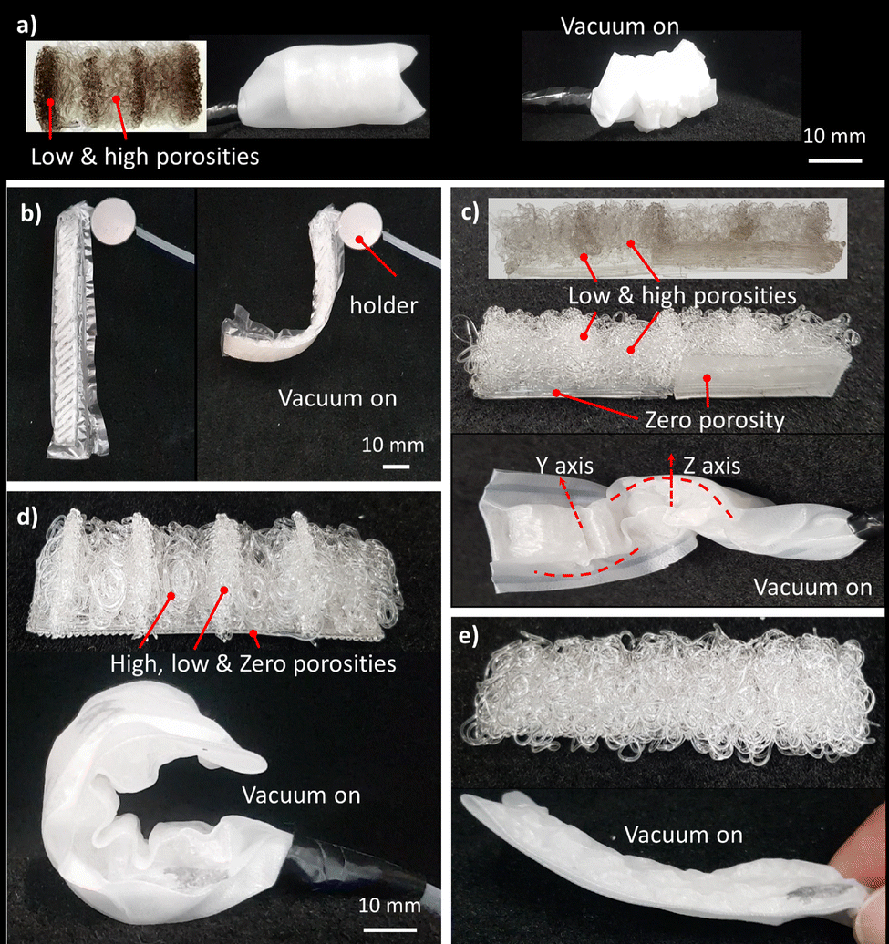 | ||
| Fig. 5 Deformation pattern for the different porosity patterns at a vacuum pressure of 95 kPa shown in Fig. 1(f): (a) contractor, (b) twisting, (c) screw pattern and (d and e) bending with (d) and without (e) a low porosity spacer. | ||
The maximum and steady-state forces of the bending actuators (in Fig. 5(d)) are plotted in Fig. 6(a) (and in Movies 4 of the ESI†). For clarity of the image, the error bars are omitted but these were lower than 10% for most (the data are provided with error bars in Fig. S5 of the ESI†). It can be observed that an increase in pressure leads to an increase in both steady-state and maximum forces. The maximum forces were in the range of 67.2 to 21.1 grams for actuators, which is 10.2 are 3.8 times their weight (6.6 and 5.5 grams, respectively). In addition, a decrease in force for higher porosity actuators is observed. This behavior is expected to be due to the lower stiffness. The lower stiffness would allow the actuator to deform such that the output force is reduced. The steady-state value of the force increases less with increasing pressure for lower porosity samples. This trend is expected to be linked to densification, which decreases the achievable deformation of lower porosity samples. Fitting a curve for the maximum and steady-state force curves gives exponents that are similar to each other. However, there is a discrepancy between the maximum and steady-state values in terms of their exponents. This discrepancy is expected to be due to the viscous component of the thermoplastic, which impacts the maximum force only. Interestingly, the power-law fits for both maximum and steady-state forces correlate well with data, which indicates that porosity could be an interesting metric to predict the mechanical performance of an SFA. However, although the power-law fit shows a good correlation further research is required to validate it for other geometries and investigate the limitations in its applicability.
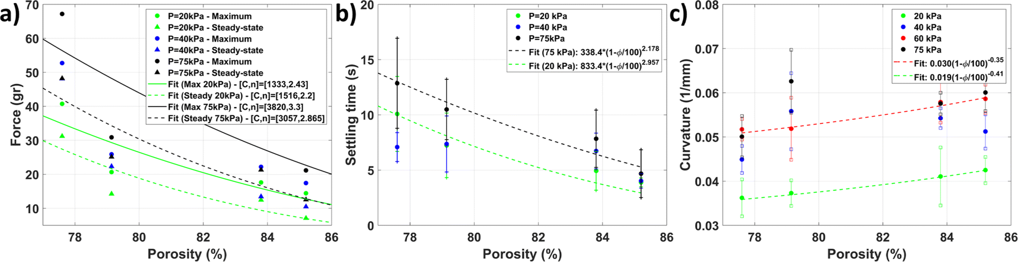 | ||
| Fig. 6 (a) Maximum and steady state force, (b) settling time, and (c) curvature versus the porosity of the high porosity section. | ||
The settling time, i.e. when the force is within 5% of the steady-state value, is plotted in Fig. 6(b). Although there is a significant spread, the trend does indicate that the settling time decreases with increasing porosity. This decrease is expected to be due to the combination of decreased density and increased energy dissipation associated with higher porosity, as seen in the soft cubes. Fits based on the average settling time for 20 and 75 kPa follow a power-law behavior with the porosity, thereby supporting that the porosity could be an interesting metric to predict the mechanical performance.
The maximum curvature versus porosity for different pressures is shown in Fig. 6(c). A nonlinear relationship can be observed between the curvature and porosity. This behavior is expected as the higher porosity actuators will deform more under the same load. Similar to the force metrics discussed previously, these curves can be described with a power-law relationship. Fitting the data shows that the curvature increases with the porosity with an exponent around the cubic root of the porosity, thereby indicating again that porosity could be a useful tool for programming deformation behavior. In addition, a nonlinear relationship between the curvature and pressure can be observed. Independent of the porosity the actuators seem to plateau at 60 and 75 kPa. This plateau is expected to be due to the densification of the porous structure. The densification means that exponentially more pressure would be required to increase the curvature. The higher densification strain of the higher porosity structures allows them to deform more before reaching this point.
The output force versus porosity is shown in Fig. 7. For comparison, the 250th cycle is used as a baseline. This cycle ensures that start-up effects do not affect the result. It can be observed that all actuators have some changes in their output force but similar to the variance shown in Fig. 6(a). However, three do not show any trend that indicates a decline in output force. The only exception is the 83.8% porosity actuator, which shows a trend that indicates a loss of output force. However, there does not seem to be an overall trend that can be explained by porosity.
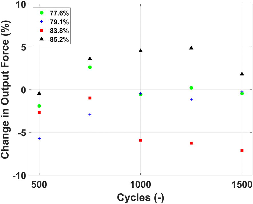 | ||
| Fig. 7 Change in output force compared to cycle 250 versus the number of pressurization cycles. | ||
Similarly, the stroke after pressurization cycles is shown in Fig. 8. It can be observed that the stroke of the actuators is still similar after 1500 cycles of pressurization for three actuators. The same actuator where a downward trend was observed for the output force shows a similar trend for its stroke, implying that some fatigue-induced behavior occurred. As this value of porosity is in between the other four it is expected that this behavior is due to a manufacturing imperfection as there is no indication that it is a porosity-induced behavior.
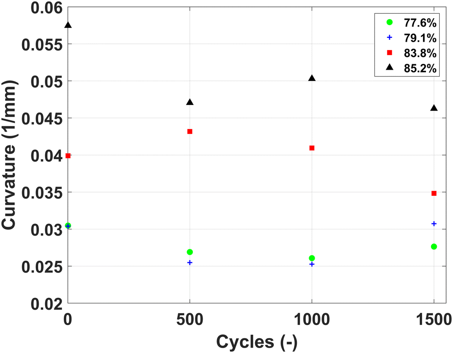 | ||
| Fig. 8 Stroke versus the number of pressurization cycles. | ||
Although only boundary cases were used in this experiment, it seems unlikely that the curve will change with intermediate points. A smooth curve is expected both in the literature34 and in our cube experiments. For instance, in Fig. 4(c)–(f) there is a smooth curve that fits the mechanical properties (compression modulus and energy dissipation) in the range of 45–89%. Therefore, as the actuator's performance is directly related to the mechanical properties, it seems reasonable to see similar smoothness in these experiments. However, the exact values will likely change if additional intermediate levels of porosity were added.
4 Conclusion
Soft fluidic actuators are a popular choice in soft robotics due to their versatility, accessibility, and (relative) simplicity. To further expand their capabilities, fabrication methods for structures that simultaneously allow for the transfer of fluidic power and have a stiffness gradient are required. Our InFoam method, as proposed in this work, can provide this capability by allowing for the direct printing of porous structures. The printed porous structures allow for fluid transport and mechanical flexibility. In addition, the structures used a hyperelastic thermoplastic to further reduce the stiffness due to the usage of a hyperelastic thermoplastic.The InFoam method is capable of mechanical programming by a single level or gradient of porosity (by combining it with normal plotting). To achieve this capability it only requires the characterization of the coil radius (with respect to the height) and the length of the extruded material per unit of movement (G) at the printing temperature. Subsequently, the InFoam method can use the developed equations to adjust the porosity of a structure by setting the height and/or extrusion speed while taking the width and height of the coiling pattern into account.
With a single level of porosity, the InFoam method can program the density, stiffness, and energy dissipation. Large changes could be realized such as an 89% lower density and scaling the compression modulus by a factor of 246. In addition, the energy dissipation in x and y could be programmed without affecting the z-direction. All of these properties were shown to correlate well through a power-law relationship with the porosity.
By printing a porosity gradient, the InFoam method allowed for a wide range of motions (including twisting, contraction, and bending). In addition, the grading was shown to be capable of programming the behavior of soft bending actuators. Specifically, it was shown that the porosity could be used to program both the output force (magnitude and settling time) and stroke.
Thus, the InFoam method can print graded porous structures that are mechanically programmed by porosity. The InFoam method allows this capability by solely adjusting the height of the nozzle and the ratio of extrusion and movement speed. An interesting observation of the printed porous structures is that the mechanical behavior of both the cubes and bending actuators could be correlated through a power-law relationship with the porosity. In addition, they showed similar trends in their changes in behavior. Further investigation of this correlation could enable tuning of the mechanical performance of soft (porous) actuators using a simple compression experiment. In addition, the stiffness grading of the InFoam method can be further investigated. A structure with high porosity has low stiffness and allows fluid transport, which can be interesting for applications such as scaffolds for more complex SFAs and support, whereas graded porosity can be a tool for soft fluidic actuators/sensors with complex deformation patterns. Lastly, an important next step for the InFoam method is to integrate the capability to print an airtight envelope. Printing of such an envelope would enable the direct 3D printing of soft fluidic actuators based on graded porous structures.
Author contributions
Conceptualization, methodology, and visualization: N. W. and A. S.; data curation, formal analysis, software, and investigation: N. W.; writing: N. W., H. K., and A. S.; supervision: H. K. and A. S.Conflicts of interest
There are no conflicts to declare.Acknowledgements
The authors would like to thank Saivimal Sridar and Farshid Jalalimoghadas for their helpful suggestions and discussions. This work was partially funded by the 4TU Dutch Soft Robotics program.Notes and references
- B. Mosadegh, P. Polygerinos, C. Keplinger, S. Wennstedt, R. F. Shepherd, U. Gupta, J. Shim, K. Bertoldi, C. J. Walsh and G. M. Whitesides, Adv. Funct. Mater., 2014, 24, 2163–2170 CrossRef CAS.
- M. Wehner, R. L. Truby, D. J. Fitzgerald, B. Mosadegh, G. M. Whitesides, J. A. Lewis and R. J. Wood, Nature, 2016, 536, 451–455 CrossRef CAS PubMed.
- N. Cheng, J. H. Low, B. W. Ang, A. J. Goh and C.-H. Yeow, IEEE Sens. J., 2018, 19, 1269–1279 Search PubMed.
- S. T. Mahon, A. Buchoux, M. E. Sayed, L. Teng and A. A. Stokes, 2019 2nd IEEE international conference on soft robotics (RoboSoft), 2019, pp. 782–787 Search PubMed.
- F. Connolly, P. Polygerinos, C. J. Walsh and K. Bertoldi, Soft Robot., 2015, 2, 26–32 CrossRef.
- R. V. Martinez, C. R. Fish, X. Chen and G. M. Whitesides, Adv. Funct. Mater., 2012, 22, 1376–1384 CrossRef CAS.
- L. Paez, G. Agarwal and J. Paik, Soft Robot., 2016, 3, 109–119 CrossRef.
- M. A. Dias, M. P. McCarron, D. Rayneau-Kirkhope, P. Z. Hanakata, D. K. Campbell, H. S. Park and D. P. Holmes, Soft Matter, 2017, 13, 9087–9092 RSC.
- M. A. Robertson and J. Paik, Sci. Rob., 2017, 2, eaan6357 CrossRef PubMed.
- S. P. Murali Babu, F. Visentin, A. Sadeghi, A. Mondini, F. Meder and B. Mazzolai, Adv. Intelligent Syst., 2021, 2100022 CrossRef.
- Y. Yamada and T. Nakamura, 2019 IEEE/RSJ International Conference on Intelligent Robots and Systems (IROS), 2019, pp. 4359–4364 Search PubMed.
- B. C. Mac Murray, X. An, S. S. Robinson, I. M. van Meerbeek, K. W. O'Brien, H. Zhao and R. F. Shepherd, Adv. Mater., 2015, 27, 6334–6340 CrossRef CAS PubMed.
- C. C. Futran, S. Ceron, B. C. Mac Murray, R. F. Shepherd and K. H. Petersen, 2018 IEEE International Conference on Soft Robotics (RoboSoft), 2018, pp. 473–478 Search PubMed.
- Y. Yamada and T. Nakamura, 2020 IEEE/SICE International Symposium on System Integration (SII), 2020, pp. 74–79 Search PubMed.
- S. Bilent, T. H. N. Dinh, E. Martincic and P.-Y. Joubert, Sensors, 2019, 19, 1968 CrossRef CAS PubMed.
- S. Bilent, E. Martincic and P.-Y. Joubert, 2020 Symposium on Design, Test, Integration & Packaging of MEMS and MOEMS (DTIP), 2020, pp. 1–4 Search PubMed.
- J. Morrow, S. Hemleben and Y. Menguc, IEEE Robot. Autom. Lett., 2016, 2, 277–281 Search PubMed.
- H. K. Yap, H. Y. Ng and C.-H. Yeow, Soft Robot., 2016, 3, 144–158 CrossRef.
- S. Walker, U. Daalkhaijav, D. Thrush, C. Branyan, O. D. Yirmibesoglu, G. Olson and Y. Menguc, 3D Print. Addit. Manuf., 2019, 6, 139–147 CrossRef.
- M. A. H. Khondoker and D. Sameoto, Progress Additive Manuf., 2019, 4, 197–209 CrossRef.
- A. Georgopoulou, L. Egloff, B. Vanderborght and F. Clemens, Actuators, 2021, 102 CrossRef.
- O. D. Yirmibesoglu, L. E. Simonsen, R. Manson, J. Davidson, K. Healy, Y. Menguc and T. Wallin, Commun. Mater., 2021, 2, 1–14 CrossRef.
- N. M. Ribe, Proc. R. Soc. London, Ser. A, 2004, 460, 3223–3239 CrossRef.
- J. I. Lipton and H. Lipson, Sci. Rep., 2016, 6, 1–6 CrossRef PubMed.
- P.-T. Brun, C. Inamura, D. Lizardo, G. Franchin, M. Stern, P. Houk and N. Oxman, Philos. Trans. R. Soc., A, 2017, 375, 20160156 CrossRef PubMed.
- X. Tian, J. Plott, H. Wang, B. Zhu and A. J. Shih, Proc. CIRP, 2017, 65, 196–201 CrossRef.
- S. Zou, D. Therriault and F. P. Gosselin, Cell Rep. Phys. Sci., 2020, 1, 100240 CrossRef.
- B. Emery, D. Revier and J. Lipton, 2021 International Solid Freeform Fabrication Symposium, 2021.
- M. Saari, M. Galla, B. Cox, P. Krueger, A. Cohen and E. Richer, 2015 International Solid Freeform Fabrication Symposium, 2015.
- S. Chiu-Webster and J. Lister, J. Fluid Mech., 2006, 569, 89 CrossRef.
- H. Yuk and X. Zhao, Adv. Mater., 2018, 30, 1704028 CrossRef PubMed.
- N. M. Ribe, M. Habibi and D. Bonn, Annu. Rev. Fluid Mech., 2012, 44, 249–266 CrossRef.
- R. J. Crawford and P. Martin, Plastics engineering, Butterworth-Heinemann, 2020 Search PubMed.
- I. Gibson and M. F. Ashby, Proc. R. Soc. London, Ser. A, 1982, 382, 43–59 Search PubMed.
- J. Schindelin, I. Arganda-Carreras, E. Frise, V. Kaynig, M. Longair, T. Pietzsch, S. Preibisch, C. Rueden, S. Saalfeld and B. Schmid, et al. , Nat. Methods, 2012, 9, 676–682 CrossRef CAS PubMed.
- C. W. Macosko, Rheology Principles, Measurements, and Applications, Wiley-VCH, 1994 Search PubMed.
- B. C. Mac Murray, C. C. Futran, J. Lee, K. W. O'Brien, A. A. Amiri Moghadam, B. Mosadegh, M. N. Silberstein, J. K. Min and R. F. Shepherd, Soft Robot., 2018, 5, 99–108 CrossRef PubMed.
- K. Larson, Can You Estimate Modulus From Durometer Hardness for Silicones? 2016, https://www.dow.com/content/dam/dcc/documents/en-us/tech-art/11/11-37/11-3716-01-durometer-hardness-for-silicones.pdf, [Accessed 3rd of March 2022].
Footnote |
| † Electronic supplementary information (ESI) available. See DOI: https://doi.org/10.1039/d2sm00524g |
| This journal is © The Royal Society of Chemistry 2022 |