
Conductive metal and covalent organic frameworks for electrocatalysis: design principles, recent progress and perspective
Jinyan
Wang†
a,
Hongyin
Hu†
a,
Shuanglong
Lu
 *a,
Jundie
Hu
b,
Han
Zhu
a,
Fang
Duan
a and
Mingliang
Du
a
*a,
Jundie
Hu
b,
Han
Zhu
a,
Fang
Duan
a and
Mingliang
Du
a
aKey Laboratory of Synthetic and Biological Colloids, Ministry of Education, School of Chemical and Material Engineering, Jiangnan University, Wuxi, 214122, China. E-mail: lushuanglong@jiangnan.edu.cn
bSchool of Materials Science and Engineering, Suzhou University of Science and Technology, Suzhou, 215009, China
First published on 30th November 2021
Abstract
Metal and covalent organic frameworks (MOFs/COFs) are emerging promising candidates in the field of catalysts due to their porous nature, chemically well-defined active sites and structural diversity. However, they are typically provided with poor electrical conductivity, which is insufficient for them to work as satisfying electrocatalysts. Designing and fabricating MOFs/COFs with high conductivity presents a new avenue towards special electrochemical reactions. This minireview firstly highlighted the origin and design principles of conductive MOFs/COFs for electrocatalysis on the basis of typical charge transfer mechanisms, that is “through space”, “extended conjugation” and “through bond”. An overview of conductive MOFs/COFs used in the electrocatalytic carbon dioxide reduction reaction (CO2RR), water splitting and the oxygen reduction reaction (ORR) was then made to track the very recent progress. In the final remarks, the present challenges and perspectives for the use of conductive MOFs/COFs as electrocatalysts including their structural optimization, feasible applications and structure–activity correlation are proposed.
 Shuanglong Lu | Shuanglong Lu received his BS and PhD degrees from Soochow University in 2013 and 2018, respectively, under the supervision of Prof. Hongwei Gu. Meanwhile, he got financial support from the Chinese government to complete his joint PhD research at University of Colorado at Boulder, USA, in Prof. Wei Zhang's group. He then joined Jiangnan University, China, as an associate professor in 2018. His current research interests mainly focus on engineering nanoporous materials including nanoporous metals and nanoporous organic frameworks, and their applications in both organic catalysis and electrocatalysis. |
1. Introduction
Energy and environmental issues have become the focus of research all over the world in the past few decades due to the serious negative impact originating from the over-exploration of fossil fuels. Clean energy conversions based on electrocatalysis are among the most efficient ways to realize the water cycle, carbon cycle and nitrogen cycle, which are beneficial for the mitigation of energy and environmental problems.1 Meanwhile, the involved electrocatalytic reactions include the carbon dioxide reduction reaction (CO2RR),2 the oxygen evolution reaction (OER),3 the hydrogen evolution reaction (HER),4 the oxygen reduction reaction (ORR)5 and the nitrogen reduction reaction (NRR),6 all of which are typically slow in kinetics or complex in final products. Thus, it is particularly significant to develop advanced electrocatalysts with high activity, selectivity and efficiency.Conventional homogeneous catalysts are usually highly selective but inefficient due to their superior well-designed chemical structures but limited mass transfer properties in electrocatalytic solutions.7 However, even though great efforts have been devoted to optimizing heterogeneous catalysts in their morphology, composition and nanostructures, it is still hard to maximize their active sites.8 Recently, metal–organic frameworks and covalent organic frameworks (MOFs/COFs), as emerging types of porous crystalline materials with molecular active sites installed, could provide homogeneous catalytic domains within the heterogeneous matrix, serving as ideal bridges between the homogeneous and heterogeneous catalysts. They have fascinating characteristics such as highly accessible areas, abundant active sites, predesigned building units and well-defined catalytic environments.9–12 The intrinsic activity of MOFs/COFs can be easily tuned and the active sites anchored inside the inherently ordered nanopores can be fully utilized. However, the applications of MOFs/COFs in electrocatalysis are far away from expected.13,14 The underlying challenge is the ability of electron transfer in MOF/COF materials, most of which have very poor intrinsic conductivities.
In a study published in 2008, Takaishi et al. proposed the first case of conductive MOFs, Cu[Cu(PDT)2] (PDT is 2,3-pyrazinedithiolate) with a high electrical conductivity of 6 × 10⁻⁴ S cm−1 at 300 K.15 This finding shed light on the potentially feasible MOF/COF electrocatalysts. Combined with their fascinating characteristics, the electrically conductive MOFs/COFs may provide an effective way to boost their electrocatalytic performance. The conductive MOFs/COFs can be either a conductor (on the order of 10 to 105 S cm−1) or a semi-conductor (on the order of 10−10 to 10 S cm−1). The conductivities of the reported conductive MOFs/COFs for electrocatalysis are statistically larger than 10−10 S cm−1, to be competent as efficient electrocatalysts.
Herein, a comprehensive minireview is made over conductive MOFs/COFs specifically for electrocatalysis. The design principle will be firstly summarized on the basis of three typical charge transfer mechanisms, that is “through space”, “extended conjugation” and “through bond”. The emphasis will be laid on the combination of electrocatalytic active sites and conductivity. Then recent progress of conductive MOFs/COFs in the electrocatalytic CO2RR, the HER/OER and the ORR will be surveyed, covering the synthesis and properties of different electroactive MOFs/COFs. It can be seen that not so many research achievements can be found in this area, so the perspectives and standing challenges will be proposed after the conclusion section. Through this minireview, we believe that researchers can systematically understand the origin and design principles for the use of conductive MOFs/COFs as electrocatalysts, which would open a new avenue for their further study in electrochemical related areas (Fig. 1).
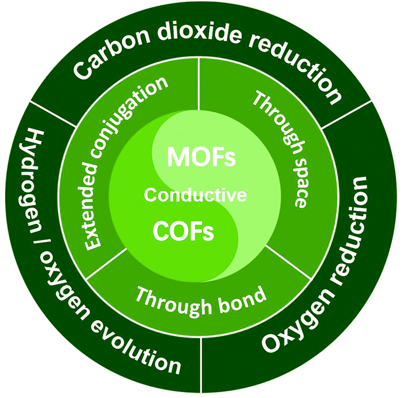 | ||
| Fig. 1 Illustration of the charge transfer mechanism involved in conductive MOF/COF based electrocatalysts and their typical electrocatalytic applications. | ||
2. Design principle
Electrical conductivity, (σ), is an intrinsic characteristic that quantifies the charge transfer in a material. It varies by orders of magnitude for different samples. Two parameters are decisive to influence the electrical conductivity. One is the charge carrier concentration and the other is the charge carrier mobility.16 In the case of conductive MOF/COF materials, highly conjugated structures are typically designed to increase the charge carrier concentration via the delocalized electrons in a large area. Strategies involving different charge transfer mechanisms are proposed to further increase the charge carrier mobility. The charge transfer mechanisms can be mainly summarized as “through space”, “extended conjugation” and “through bond”. Each charge mechanism contains several different structure types. On the basis of diverse charge transfer mechanisms, two main design strategies are typically used to embrace electroactive sites. The first one is that through the modulation of charge transfer, the active sites are in situ created due to the uneven distribution of electrons or changes in the oxidation states. Another strategy is matching electroactive building blocks without affecting the charge transfer ability.2.1 Origin and structural design in the “through space” mechanism
In the “through space” conduction mechanism, charges are generally transferred between MOF/COF layers17 (Fig. 2a). The most possible reason for that is the π–π stacking between the organic ligand layers, and electrons are transported along the c axis. Tetrathiafulvalene (TTF) and its derivatives functionalized with aldehyde (–CHO), carboxy (–COOH), amino (–NH2) or thioether (–SR) groups (Fig. 2b) are excellent electron donors because they can be reversibly oxidized to form stable free radical cations TTF˙+ and TTF2+ to promote redox activity.18 Besides, they can be easily functionalized by coordination groups. Due to their high π–π accumulation and close contact between spatial molecules,19 when TTF is coordinated with metals to form MOFs, or linked with another organic unit to synthesize COFs, most oxidized TTF-based polymers have a high degree of electrical conductivity. Nguyen et al. studied the properties of a carboxylate functionalized TTF structure as a unit to synthesise three-dimensional coordination polymers with different metals (K, Rb and Cs). The conductivity can reach up to 10−3 S cm−1.20 TTF-based COFs also show good electrical conductivity. Li and co-workers reported a three-dimensional TTF-COF, which has adjustable conductivity which can be as high as 1.4 × 10⁻² S cm−1 at 120 °C. The densely packed two-dimensional grids facilitate the delocalization of TTF radical cations to enhance their conductivity.21 Cai et al. doped electron acceptors in TTF-based COFs. The conductivity of the material reached 2.8 × 10⁻³ S cm−1.22 Apparently, the different functional TTF units, coordination metals ions in MOFs, and matching units in COFs could provide a series of specialized structures, which may show remarkable electrocatalytic activities.23–25 Notably, the conductivity of TTF-based polymers is highly correlated with the distance between the S atoms in adjacent TTF nuclei. With a decrease of the distance, the overlap of these orbitals and the dispersion of the bands formed by atom S and 3pz orbitals will increase correspondingly. Park et al. synthesized four isomorphic metal-coordinated TTF-based MOFs (metals including Mn, Co, Zn and Cd). They found that among them, the Cd-MOF with the shortest adjacent S–S distance has a highest conductivity of 2.86 × 10⁻⁴ S cm−1.25 It presents a novel viewpoint in designing conductive MOF/COF based electrocatalysts.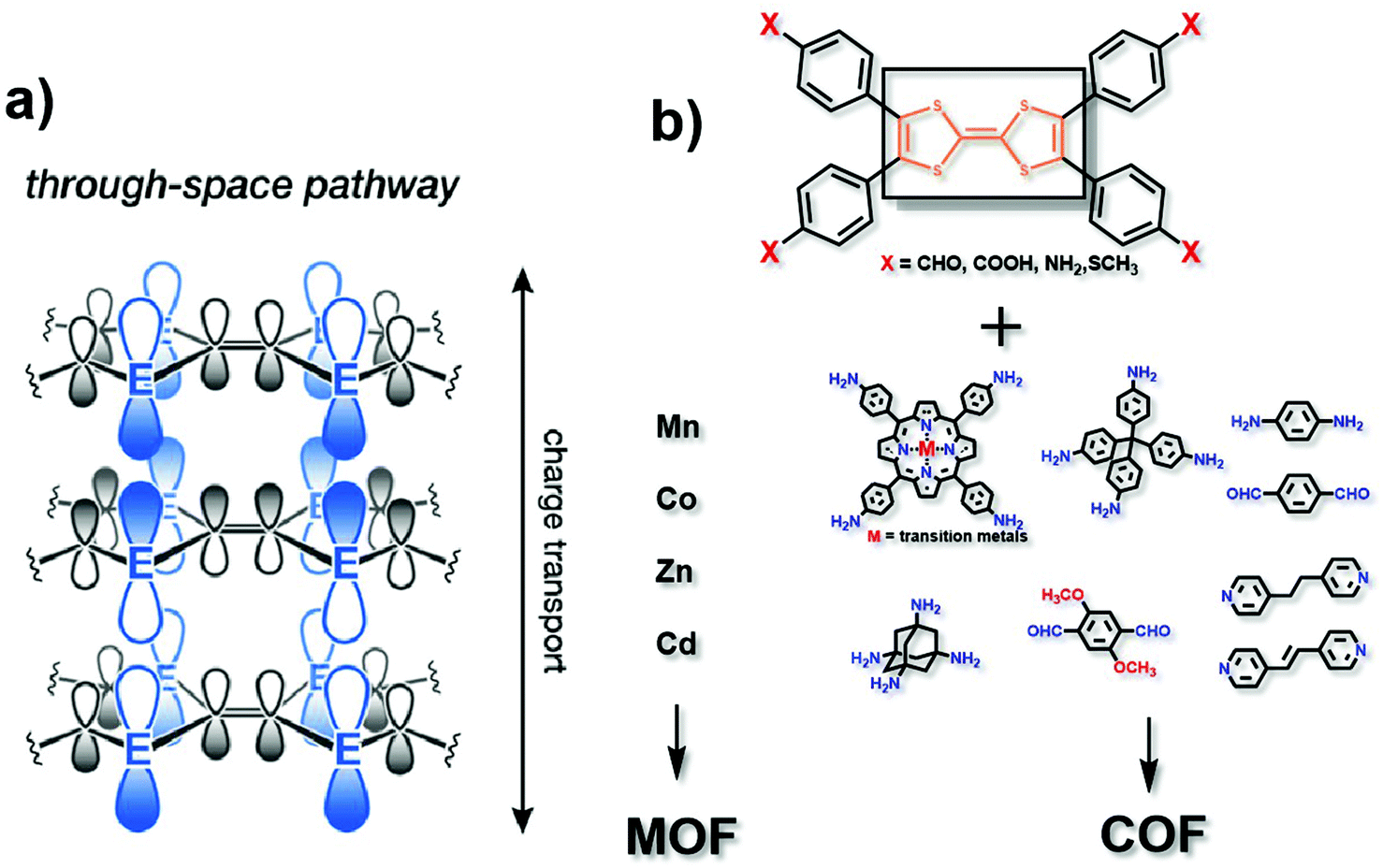 | ||
| Fig. 2 (a) Charge transport pathway of the through space mechanism. This figure has been adapted from ref. 17 with permission from the American Chemical Society, copyright 2020; (b) structure of the TTF analog, matching metals (for MOFs) and matching organic ligands (for COFs). | ||
2.2 Origin and structural design in the “extended conjugation” mechanism
In the mechanism of “extended conjugation”, structures usually contain π–d full in-plane conjugation in the layer17 (Fig. 3a). Charge transfer can be easier with the extended structures both in MOFs and COFs. Typically, transition metal ions are coordinated with polycyclic aromatic hydrocarbons or organic ligands with chelating structures to form the full in-plane conjugation. The electronic structure of such porous polymers is regarded as similar to that of the in-plane π conjugated structure of graphene, which has a high level of conductivity.26 The most typical organic unit coordinated with transition metal ions is 2,3,6,7,10,11-hexaiminotriphenylene (HITP). In 2014, Sheberla et al. discovered for the first time the excellent conductivity of the Ni3(HITP)2 coordination polymer. Its pellet conductivity and film conductivity were 2 and 40 S cm−1, respectively. Theoretical calculations show that the electronic structure of Ni3(HITP)2 is metallized, even though in fact the experimental value of conductivity is not so excellent as metals.27 The possible reason for this can be due to the inevitable defects including interface defects, permanent grain boundaries and strike-slip fault defects in the material, which may break the electron delocalization and introduce a band gap subsequently resulting in a decrease in the conductivity.28 Although these defects may be unfavourable for the conductivity, they can facilitate the catalytic activity to some extent.29–31 It is necessary to balance the decreased conductivity and increased numbers of active sites. Defects should be introduced into the framework without greatly destroying the conductivity of the material. Typically, defects would not exist in the entire framework, and therefore, experiments and calculations should be combined to exert rational control over the degree, number, and location of defects. It is notable that not all electrocatalytic active sites are derived from defects, and in these cases, the defects should be avoided as much as possible to maintain conductivity. This combination in this π–d full in-plane conjugation can be extended to different metal ions such as Cu2+ and Co2+,32–35 and different ligands such as 2,3,6,7,10,11-hexahydroxytriphenylene (HHTP), 2,3,7,8,12,13-hexahydroxytricycloquinazoline (HHTQ), 2,3,6,7,10,11-hexaoxotriphenylene (HOTP) and tetrahydroxyquinone (THQ) (Fig. 3b).36–40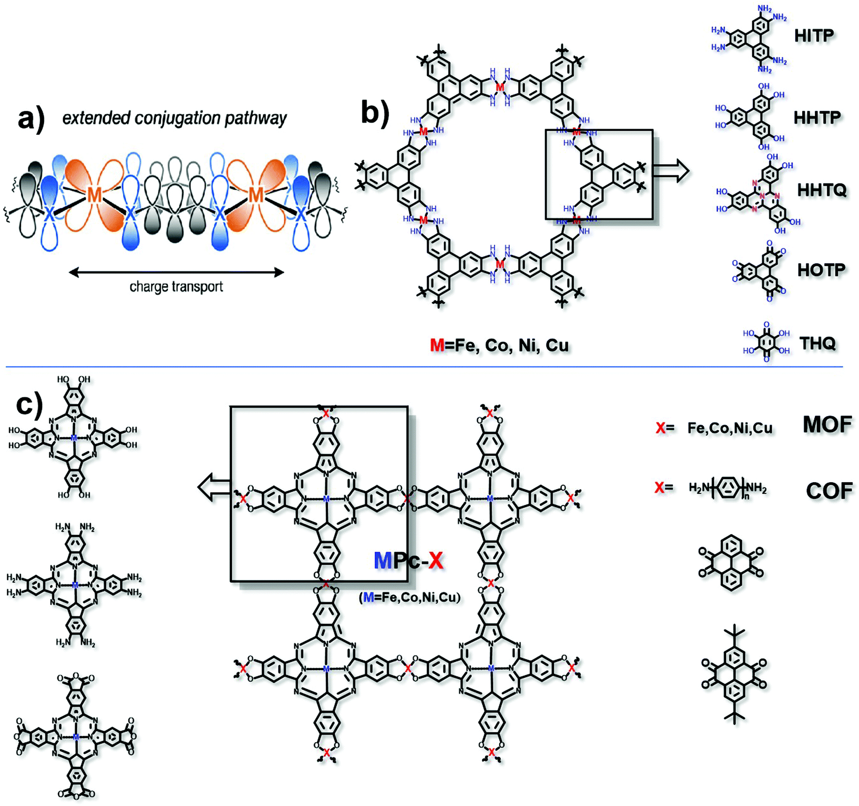 | ||
| Fig. 3 (a) Charge transport pathway of extended conjugation. This figure has been adapted from ref. 17 with permission from the American Chemical Society, copyright 2020; (b) structure of HITP analog based MOFs; and (c) structure of MPc-X, matching metals (for MOFs) and organic ligands (for COFs). | ||
Another typical example is the π–d conjugation formed between transition metal ions and phthalocyanine (Pc) (Fig. 3c). For example, Zhang et al. obtained a NiPc-COF by condensing octaamine-functionalized, Ni-coordinated Pc and tert-butylpyrene-tetraone (tBu-PT). It is a COF network connected by pyrazine. Due to the in-plane π delocalization and the ordered out-of-plane π–π stacking along the c axis, the transmission of electrons in the entire material is effectively enhanced. Through ultraviolet-visible spectra, it is found that pyrazine is responsible for extended conjugation. What's more, the electron is proved to transfer from the electron donating pyrazine group to the electroactive site nickel phthalocyanine. The conductivity is 3.77 × 10⁻⁶ S cm−1.41 The replaceable metal ions include Fe2+, Co2+ and Cu2+. Besides, Han et al. reported a conductive COF synthesized by the reaction between octacarboxy-functionalized, Co-coordinated Pc and 1,4-phenylenediamine (PD) or 4,4′-biphenyldiamine (BD), the conductivities of which can reach 3.7 × 10⁻⁵ S cm−1 and 1.6 × 10⁻⁵ S cm−1, respectively.42 Similarly, by varying the functional groups in both HITP and Pc units, the types of coordination metals and the matching units for the HITP or Pc unit (in the COF only), excellent electrocatalysts based on conductive MOFs/COFs can be prepared and optimized.
2.3 Origin and structure design in the “through bond” mechanism
Since the d orbital of the metal and the π orbital of the organic ligand are highly overlapped, the “through bond” mechanism is also a vital way of electron transport17 (Fig. 4a). Different from the π–d full in-plane conjugation in the “extended conjugation” mechanism, the metal ions and ligands here are not in the same plane. The typical example is 2,5-dioxido-1,4-benzenedicarboxylate (DOBDC) and its derivatives, such as 2,5-sulfhydryl-1,4-benzenedicarboxylate (DSBDC), which are coordinated with transition metal ions such as Mg2+, Mn2+, Fe2+, Co2+, Ni2+, Cu2+ and Zn2+ (Fig. 4b). The symmetrical orbital is conducive to energy overlap for better charge transfer. Modulating the suitable orbital interaction will not only favor the conductivity, but also optimize the electrocatalytic activity. Previous studies have shown that if sulfur atoms with lower electronegativity substituted the bridged oxygen atoms, the charge mobility can be facilitated.43 What's more, Sun et al. found that the conductivity can be increased by six orders of magnitude if ferric ions substituted the bivalent manganese ions.44 Therefore, bridging atoms and coordinated metal ions on the basis of the “through bond” mechanism in conductive MOFs need to be carefully optimized to find their suitable electrocatalytic conditions.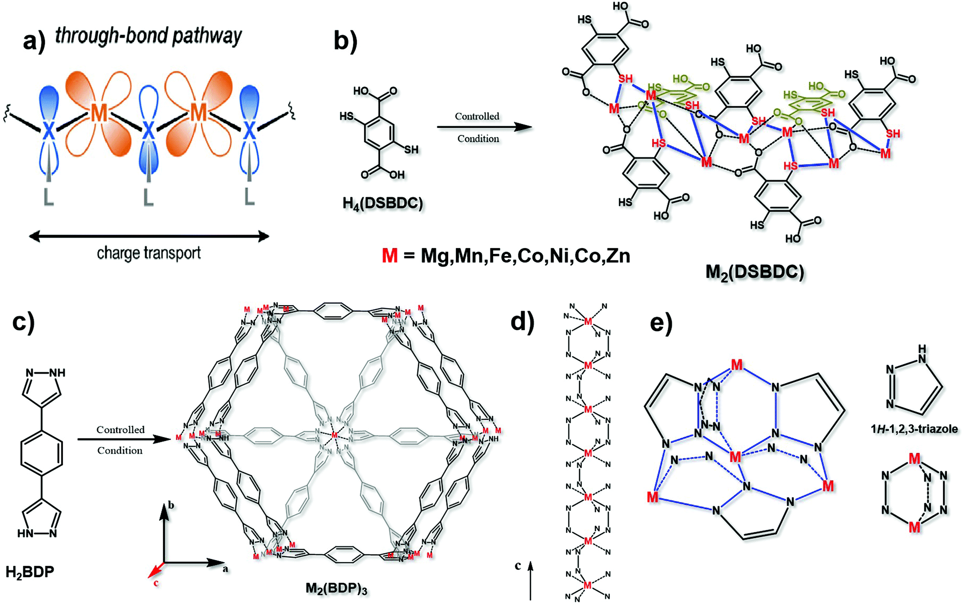 | ||
| Fig. 4 (a) Charge transport pathway of the through bond mechanism. This figure has been adapted from ref. 17 with permission from the American Chemical Society, copyright 2020; (b) synthesis of M2(DSBDC), and the charge transport chain (–M–S–) in this material. This figure has been reproduced from ref. 43 with permission from the American Chemical Society, copyright 2013; and (c) synthesis of M2(BDP)3. (d) The charge transport chain (–M–N–N) in the c axis of M2(BDP)3. These two figures have been reproduced from ref. 16 with permission from Springer Nature, copyright 2018. (e) Charge transport 3D net (–M–N–N–) in M(tri)2 with its structural units. This figure has been reproduced from ref. 45 with permission from the American Chemical Society, copyright 2018. | ||
Notably, the transmission of electrons through bonds can be along a one-dimensional long chain of alternating metal and heteroatoms (Fig. 4d), or along a three-dimensional network of alternating metal and heteroatoms, such as Fe(tri)2 (tri = 1,2,3-triazolate)45 (Fig. 4e). Conductive MOFs like this which contain azolate ligands, such as 1,4-benzenedipyrazolate (BDP), usually conform to the “through bond” mechanism. In particular, if the metal ion is iron with a mixed valence, the charge mobility between adjacent atoms can be increased, resulting in excellent conductivity.44 Aubrey and co-workers reported the synthesis of Fe-MOFs with BDP as a ligand. They verified that the enhancement of conductivity is caused by the fractional reduction of Fe2(BDP)3 (Fig. 4c and d), and when it is reduced to K0.78Fe2(BDP)3, the conductivity is as high as 0.025 S cm−1. This polymer is composed of octahedral d5/6 transition metals, bridged by nitrogen-donor and π-acid ligands. In this coordination environment, the π orbitals between the metal and organic ligand can achieve the maximum overlap, effectively promoting electron delocalization, minimizing the reorganization energy on electron transfer and facilitating the electronic coupling between adjacent metals.16 Similar results were also obtained by Xie and co-workers that the conductivity is tunable by varying the extent of the Fe2+/3+ mixed valence. When exposing Fe2(BDT)3 (H2BDT is 5,5′-(1,4-phenylene)bis(1H-tetrazole)) in air for 30 days, the average conductivity reached 1.2 S cm−1 and the best is 1.8 S cm−1, the reason for which is the partial oxidation of the material resulting in Fe3+ defects.46 Therefore, changing the oxidation state of metal ions is also a feasible way in the “through bond” mechanism to design conductive MOF-based electrocatalysts.
2.4 Other mechanisms
In addition to the three mechanisms mentioned above, there are still other mechanisms. For example, a “redox hopping” mechanism refers to the situation that the components in MOFs/COFs with redox activity are relatively far apart such that their orbitals cannot directly overlap. It is found that the longer the distance between the redox active sites is, the lower the charge mobility is. However, almost no existing conductive MOF/COF based electrocatalysts follow this mechanism, so we will not discuss it in detail here. Additionally, there is another mechanism denoted as “guest-promoted”, which refers to improving the conductivity by introducing highly loaded electroactive molecules into the pores of MOFs/COFs. As it is different from the intrinsic conductivity of MOFs/COFs, it will not be covered as well.17Very recently, Jiang et al. discovered a kind of COF with a new conductive mechanism. This COF with a planar conformation uses isoindigo as an organic linker, in which the π electron cloud of the building unit can be unidirectionally arranged at the bottom and top of the xy plane to ensure the horizontal overlap of the orbital. These two characteristics not only greatly reduce the recombination energy of carrier transmission, but also trigger the electronic coupling effect. Therefore, although this COF does not have a conjugated structure, it also has ultra-high electron mobility, with a conductivity of 10−6 S cm−1. This new finding will open up a new direction for the development of conductive COF-based electrocatalysts.47
3. Applications of conductive MOFs/COFs as electrocatalysts
Highly conductive MOFs/COFs are expected to exhibit ideal performance in the field of electrocatalysis due to their excellent characteristics. In the following, several concerns will firstly be proposed and discussed, including the superiority of conductive MOFs/COFs when compared with non-conductive MOFs/COFs on conductive supports, stability, durability and limitations of conductive MOFs/COFs during electrocatalysis, and then, an overview of conductive MOFs/COFs used in the electrocatalytic carbon dioxide reduction reaction (CO2RR), water splitting and the oxygen reduction reaction (ORR) will be made to track the very recent progress.3.1 Several concerns of conductive MOFs/COFs as electrocatalysts
As MOFs/COFs have fascinating characteristics such as highly accessible areas, abundant active sites, predesigned building units and well-defined catalytic environments, they are highly promising in electrocatalysis if the electrons can be easily transferred to active sites.9–12 Compared with the already-developed strategy that supports non-conductive MOFs/COFs on conductive supports,48–52 intrinsic conductive MOFs/COFs have distinct benefits. For one thing, the whole structure is conductive and the electron transfer would not be hindered throughout all active sites,53,54 while for the supported non-conductive MOFs/COFs, it is still difficult for electrons to reach the outer layer of MOFs/COFs.51–55 For another thing, in contrast to the straightforward structure design and clear porosity of intrinsic conductive MOFs/COFs, the introduction of additional supports brings about more factors needed to be considered, such as the suitable matching and successful loading of MOFs/COFs on conductive supports,50,52,56 the interface engineering of these two components and the negative effects on porosity during the synthesis.Stability is another big concern when we evaluate the performance of electrocatalysts. Conductive MOFs/COFs show variable stability with different materials and in different electrolytes.57 In alkaline media, various conductive MOFs/COFs can maintain their structures after electrocatalysis, accompanying high catalytic performance after a long-term stability test.58–60 Some research studies verified the stability of conductive MOFs during electrocatalysis using multiple characterization methods.42,59 The results show that the metal atoms in the conductive MOFs were not immersed and even their valence state did not change. What's more, their pore structures also remained the same without collapse, indicating their superior stability. The electrocatalysis under acidic electrolytes is reported to potentially change the structure of conductive MOFs/COFs. For example, when TTF-Por(Co)-COFs served as electrocatalysts for the CO2RR, the stability is relatively poor, with a sharp decrease in the current density and selectivity.24 The possible reason is that the pyrrole in the porphyrin ring was hydrogenated, resulting in the overall structure change of TTF-Por(Co)-COFs. The properties are quite similar to the corresponding monomers, such as nickel porphyrin62 and cobalt phthalocyanine.63 Even the polarity of the solvent may also induce structural changes, especially for conductive COFs, whose adjacent layers are typically held together by π–π stacking. A conductive COF synthesized with a TTF monomer is reported to be sensitive to polar solvents.22 When it is exposed to polar solvents such as ethanol, its crystallinity will decrease and the stacked structure will rearrange.64 However, this change is reversible. After desolvation, the conductive COF will return to its original state. Interestingly, as the polar solvent is added, the conductivity of the COF increases instantly. This is because the polar solvent increases the transfer rate of electrons and holes. However, this increase in conductivity is minimal compared to the overall conductivity. In addition to the change in the organic ligands and their spatial locations, metal ions could also be oxidized or reduced during electrocatalysis. When in an alkaline KOH electrolyte solution, the Cu2+ in Cu-THQ was reduced to Cu+ and copper clusters in the CO2RR catalytic process.65 This process is not that reversible and the copper clusters are difficult to oxidize back to Cu2+, only if it undergoes prolonged exposure to the air. Apart from the factors mentioned above, high temperatures and the introduction of guest molecules can also cause structural changes.66 A few conductive MOFs will also be affected by water, leading to the hydrolysis of the secondary building units.67 When the structure of conductive MOFs/COFs changes, the catalytic activity and conductivity will also be affected.
The stability of some conductive MOFs/COFs is a standing concern for their practical applications. In addition, the conductivity of most MOFs/COFs could be further optimized. Although it is difficult to make their electrical conductivity reach the same level as metals, there is still a lot of room for improvement in the current electrical conductivity. Also, the efficient mass transfer in the micropores of conductive MOFs/COFs should be well guaranteed by the thorough elimination of contamination. Only when the structural stability, conductivity and mass transfer could be balanced well, conductive MOFs/COFs could maximize their strength in electrocatalysis.
3.2 Carbon dioxide reduction reaction (CO2RR)
Nowadays, excessive carbon dioxide emissions have led to the destruction of ecosystems and global climate warming. Therefore, it is necessary to convert carbon dioxide into methane, ethane, methanol, ethanol and other valuable chemicals for recycling to accelerate the carbon cycle.1,68 The electrocatalytic carbon dioxide reduction reaction (CO2RR) is considered as an efficient and environmentally benign pathway to convert carbon dioxide into high-value carbon-containing products. The CO2RR can be expressed using the following reaction:| xCO2 + nH+ + ne− → Product + yH2O |
Metal phthalocyanine complexes with M–N4 (M = Fe\Co\Ni) structures are considered to provide active sites for the CO2RR, but usually the selectivity and current density are not very satisfactory.69 Yi et al. synthesized NiPc–NiO4, a conductive MOF based on phthalocyanine with excellent performance. The current density is 34.5 mA cm−2 at −1.2 V vs. RHE. The selectivity to CO is as high as 98.4%. After 10 hours of the stability test, the selectivity is still at an acceptable level of 86%. Theoretical calculations have proved that the active sites are in nickel. What's more, the Ni in the phthalocyanine center has a strong adsorption capacity for carbon dioxide. Its excellent electron-rich environment and reducibility make it an ideal catalytic active site, resulting in a higher current density in the CO2RR process than the ordinary M–N4 structure.60 In addition to the MOF of nickel phthalocyanine, nickel or cobalt phthalocyanine based COFs also exhibit excellent CO2RR performance. Their selectivity toward CO is higher than 90%.23,24,41,41,59
In addition to the metal phthalocyanine complexes, Majidi et al. synthesized a two-dimensional copper-based conductive MOF, Cu-THQ. At −0.45 V vs. RHE, the current density is as high as 173 mA cm−2, the average Faraday efficiency of the product CO reaches 91%, and the turnover frequency is as high as 20.82 s−1. Among them, copper ions and adjacent oxygen are proved to be the catalytic active centers.65 Based on nitrogen-rich electron-rich tricyclic quinazoline (TQ), Liu et al. coordinated Cu2+ and Ni2+ with a multi-site catechol ligand to obtain a two-dimensional nanosheet M3(HHTQ)2. Copper ions and nickel ions are uniformly distributed in the hexagonal lattice. Through comparison, it is found that Cu3(HHTQ)2 has high selectivity to methanol. In addition to hydrogen, methanol is the only product of the CO2RR. The highest Faraday efficiency reaches 53.6%, which is about 100 times those of Ni3(HHTQ)2 and Cu3(HHTP)2 and it maintains good stability.35
Combining the highly conductive TTF with electroactive species also works for the CO2RR. Wu et al. reported a COF material constructed with TTF and two-dimensional cobalt porphyrin. The introduction of TTF can enhance the electron transfer ability from TTF to the cobalt porphyrin ring, decreasing the active energy and facilitating the efficiency of the CO2RR in water. Its Faraday efficiency of reducing carbon dioxide to carbon monoxide can reach 95%.24 For TTF-based COFs, Co-TTCOFs show the best Faraday efficiency of CO, which is up to 99.7%.23
As one of the most high-value products from the CO2RR, ethylene is produced through a multi-proton coupled electron transfer mechanism. A conductive MOF based on phthalocyanine, PcCu–Cu–O, has been proven to be applicable to the reduction of carbon dioxide to ethylene. Due to the synergy between the copper-phthalocyanine unit and the other unit CuO4, the current density at −1.2 V vs. RHE is 7.3 mA cm−2. The Faraday efficiency of ethylene is 50%. The selectivity is higher than that of discrete molecular copper-phthalocyanine.61 All of the typical conductive MOFs/COFs as electrocatalysts in the CO2RR have been summarized in Table 1.
| Materials | MOF/COF | Conductive mechanism | Conductivity (S cm−1) | Media | Organic ligand | Main product | Faradaic efficiency (FE) | Ref. |
|---|---|---|---|---|---|---|---|---|
| PcCu–Cu–O | MOF | Extended conjugation | — | 0.1 M KHCO3 | Phthalocyanine | C2H4 | 50% | 61 |
| NiPc–NiO4 | MOF | Extended conjugation | 4.8 × 10⁻⁷ | 0.5 M KHCO3 | Phthalocyanine | CO | ∼100% | 60 |
| Cu3(HHTQ)2 | MOF | Extended conjugation | (2.74 ± 0.15) × 10−5 | 0.1 M KHCO3 | HHTQ | CH3OH | 53.6% | 35 |
| Cu2O@CuHHTP | MOF | Extended conjugation | 4.3 × 10⁻⁸ | 0.1 M KCl/0.1 M KHCO3 | HHTP | CH4 | 73% | 70 |
| Cu-THQ | MOF | Extended conjugation | 1.5 × 10⁻⁷ | 1 M C5H14CINO/1 M KOH | THQ | CO | 91% | 65 |
| TTF-Por(Co)-COF | COF | Through space | 1.32 × 10⁻⁹ | 0.5 M KHCO3 | TTF | CO | 95% | 24 |
| Co-TTCOF | COF | Through space | — | 0.5 M KHCO3 | TTF | CO | 99.7% | 23 |
| CoPc-PI-COFs | COF | Extended conjugation | 3.7 × 10⁻⁵ | 0.5 M KHCO3 | Phthalocyanine | CO | 87%–97% | 42 |
| 1.6 × 10⁻⁵ | ||||||||
| NiPc-COF | COF | Extended conjugation | 3.77 × 10⁻⁸ | 0.5 M KHCO3 | Phthalocyanine | CO | ∼100% | 41 |
| CoPc-PDQ-COF | COF | Extended conjugation | 3.68 × 10⁻⁵ | 0.5 M KHCO3 | Phthalocyanine | CO | 96% | 59 |
3.3 Water splitting
Hydrogen (H2) has been regarded as an ideal substitute for non-renewable fossil energy due to its high energy density and environmental benignity. Nowadays, water splitting is considered as the most convenient, eco-friendly and efficient way for H2 generation. Water splitting involves both the cathodic reaction, the hydrogen evolution reaction (HER), and the anodic reaction, the oxygen evolution reaction (OER). The OER always occurs through a four-electron pathway and can be expressed using the following reactions:| 2H2O − 4e− → O2 + 4H+ (acid media) |
| 4OH− − 4e− → O2 + 2H2O (basic media) |
Meanwhile, the HER can be expressed using the following reactions:
| 2H+ + 2e− → H2 (acid media) |
| 2H2O + 2e− → H2 + 2OH− (basic media) |
So far, noble metal catalysts, such as IrO2/RuO2 and Pt/C, are still the state-of-the-art catalysts for the OER and HER, respectively, which drastically restricts their industrial application on a large scale.71 Thus, seeking effective and durable new types of electrocatalysts for water electrolysis is still urgent and vital.
Heretofore, an HER/OER catalyst was limited by the activity and number of active sites as well as charge transfer capability. MOFs are anticipated to be ideal candidate materials for electrocatalysis, including the HER and OER, due to their large surface area, unique pore/channel structures, and abundant accessible metal sites. The high conductivity of conductive MOFs enables OER and HER catalysts to have efficient electron transfer based on the above advantages.72
Wang et al. proposed that Cu3(HITP)2 is an ideal bi-functional catalyst for the HER and OER in overall water splitting through calculation. The HER performance of Cu3(HITP)2 is even superior to that of the precious Pt-based catalyst. Meanwhile, Co3(HITP)2 and Zn3(HITP)2 are excellent OER catalyst candidates for IrO2/RuO2. The calculation result elucidated the possibility of the application of conductive MOFs in the field of water splitting.73
Metal ions coordinated with N/O/S units typically show effective electronic coupling, which can reduce the adsorption energy of intermediates such as OH*, O* and OOH*, and present excellent catalytic activity for the OER.74 Li et al. reported the application of phthalocyanine-based MOFs (NiPc–NiFex MOFs) as efficient OER catalysts. By replacing an appropriate number of Ni–O4 sites with Fe–O4 sites in NiPc–Ni, the optimal bimetallic conductive MOF delivers a low overpotential of 300 mV at 10 mA cm−2 and an ultra-high TOF value of 1.943 s−1 at η = 300 mV. After 1000 CV cycles, the OER polarization curve only displays a slightly positive shift (33 mV shift at 50 mA cm−2), indicating excellent stability.75 Xing et al. studied the OER performance of Co3(HITP)2. The overpotential of Co3(HITP)2 is less than those of RuO2 and IrO2 under 1.0 M KOH. The synergistic effect of the cobalt ion and organic ligand provides higher activity. During the catalytic process, a change in the valence state of the cobalt ion is observed, which verifies that the cobalt ion is the catalytic active center of the OER.34 In fact, both Ni–N4 and Ni–O4 sites help catalyse the OER.76
Replacing the Ni in Ni3(HHTP)2 with a certain amount of Ru can make the conductive MOFs bifunctional catalysts.37 As an electrocatalyst for OER, its onset potential is 1.52 V and the potential to reach 10 mA cm−1 is 1.62 V. Typical conductive MOFs as electrocatalysts in the OER have been summarized in Table 2.
| Materials | MOF/COF | Conductive mechanism | Media | Organic ligand | Tafel slope (mV dec−1) | Overpotential (η) (mV) | Ref. |
|---|---|---|---|---|---|---|---|
| Ni5.7Ru0.3(HHTP)3(H2O)x | MOF | Extended conjugation | 0.1 M KOH | HHTP | 61 | η onset = 290 | 37 |
| Co3(HHTP)2 | MOF | Extended conjugation | 1.0 M KOH | HHTP | 83 | η onset = 340 | 76 |
| LSCF@Ni3(HITP)2 | MOF | Extended conjugation | 1.0 M KOH | HITP | 95 | η 10 = 272 | 77 |
| NiPc–Ni | MOF | Extended conjugation | 1.0 M KOH | Phthalocyanine | 83 | η onset = 319 | 75 |
| η 10 = 427 | |||||||
FeNi–DOBDC (Fe![[thin space (1/6-em)]](https://www.rsc.org/images/entities/char_2009.gif) :Ni = 3:1) :Ni = 3:1) |
MOF | Through bond | 1.0 M KOH | H4DOBDC | 49 | η 50 = 270 | 78 |
| η 100 = 287 | |||||||
| η 155.5 = 300 | |||||||
| Co0.6Fe0.4-MOF-74 | MOF | Through bond | 1.0 M KOH | H4DOBDC | 56 | η 10 = 280 | 79 |
| NiCo-BDC | MOF | Through bond | 1.0 M KOH | BDC | 61 | η 10 = 230 | 80 |
| η 100 = 292 | |||||||
| Fe/Ni2.4/Co0.4-MIL-53 | MOF | Through bond | 1.0 M KOH | BDC | 52.2 | η 10 = 219 | 81 |
| η 20 = 236 | |||||||
| Fe/Ni1.6-MIL-53/C | MOF | Through bond | 1.0 M KOH | BDC | 37.8 | η 10 = 258 | 81 |
| Fe/Ni2.0-MIL-53/C | MOF | Through bond | 1.0 M KOH | BDC | 45.5 | η 10 = 258 | 81 |
| Fe/Ni2.4-MIL-53/C | MOF | Through bond | 1.0 M KOH | BDC | 48.7 | η 10 = 244 | 81 |
Compared with conductive MOFs used in the OER, only few works reported conductive MOFs in the HER. Huang et al. selected hexaiminohexaazatrinaphthalene (HAHATN), an analog of HATN, as an organic ligand to fabricate conductive MOFs and coordinate Ni2+ ions (Ni3(Ni3·HAHATN)2). Hexaazatriphenylene (HATN) is an N-containing tris(bidentate) polyheterocyclic ligand with an electron-deficient conjugated structure. The bidentate tertamine of HATN can coordinate metal ions with a two-coordinated (M–N2) moiety and endow metal atoms with more variable oxidation states during catalysis. The bimetallic sited conductive MOFs exhibit outstanding HER performances in alkaline solution, with a low overpotential of 115 mV at 10 mA cm−2 and the corresponding Tafel slope of 45.6 mV dec−1. After the 10 h test, the HER current retains 83.4% of the initial activity, which exhibits promising electrocatalytic stability.82
Compared with the remarkable progress of conductive MOFs in the OER, a number of COF-based OER electrocatalysts were also reported. However, the electrical conductivities of almost none of them were reported, so they will not be included in this review. As the concept of conductive COFs was put forward later than MOFs, it is anticipated that conductive COFs will have their correlation between the structures and electrocatalytic performance in the OER in the near future considering their already developed electrocatalytic applications and theoretical calculations.
3.4 Oxygen reduction reaction (ORR)
The electrochemical oxygen reduction reaction (ORR) is one of the most important reactions in the field of energy conversion. As is known to all, the ORR is always divided into two pathways: 2e− ORR for generating H2O2 and 4e− ORR for producing H2O. The 2e− pathway can be expressed using the following reactions to electro-synthesize H2O2:| O2 + 2H2O + 2e− → H2O2 + 2OH− (basic media) |
| O2 + 2H+ + 2e− → H2O2 (acid media) |
While 4e− ORR, expressed with the following reactions, can be used in proton-exchange membrane fuel cells (PEMFCs) and rechargeable metal–air batteries
| O2 + 2H2O + 4e− → 4OH− (basic media) |
| O2 + 4H+ + 4e− → 2 H2O (acid media) |
However, the coexistence of the two approaches will lead to energy waste. Similar to the CO2RR, selectivity is one of the decisive criteria for determining the performance of electrocatalysts towards the ORR.
It has been proved that the bonding motif of M–N4 (M = non-platinum group metal chelated in a nitrogen-containing environment) can catalyse the ORR process with high activity.83–85 As is known to all, the ORR is always divided into two pathways, they are 2e− ORR for generating H2O2 and 4e− ORR for producing H2O.71 In 2016, Miner et al. discovered for the first time that Ni3(HITP)2 can be used to catalyse the four-electron ORR process in an alkaline medium, and it did not show obvious morphological changes during a long electrochemical cycle. It is found that the active site of catalysis is on the organic ligand.86,87
In the next year, Sun et al. found through theoretical calculations that Ni3(HITP)2 can catalyse the two-electron process of the oxygen reduction reaction to generate H2O2. They even proposed that besides the Ni–N4 part that can be used as a catalytically active site, the H atom which is directly connected to the Ni atom also shows catalytic activity, even higher than that of Ni–N4. First-principles molecular dynamics simulations show that Ni3(HITP)2 also exhibits excellent thermodynamic stability. Through simulation and calculation of the adsorption configuration, it is confirmed that the electron cloud between the positively charged hydrogen atom and the adsorbed oxygen has a large overlap, and there is a strong interaction between them. The enhanced adsorption energy is conducive to the ORR process. In addition, Ni3(HITP)2 is more beneficial to the ORR process of the two-electron generation of hydrogen peroxide, and calculations show that the selectivity of the process can be as high as 88%.88 However, even though credible theoretical predictions have been made, there have been few reports on the experimental results using conductive MOFs/COFs as ORR electrocatalysts.
4. Conclusion and perspective
Developing advanced electrocatalysts with high activity, selectivity and efficiency is of great importance to clean energy conversions. As promising candidates, conductive MOFs/COFs can not only provide high atomic utilization, easy mass transfer and well-defined active sites, but also establish a highway for electrons, which is highly favourable for the enhancement of electrocatalytic performance. Through this review, we proposed the design principles of conductive MOF/COF electrocatalysts on the basis of three typical charge transfer mechanisms. The corresponding featured structures are summarized to guide the rational design. In addition, the very recent progress of conductive MOFs/COFs used in different electrocatalytic reactions including the CO2RR, OER/HER and ORR is surveyed. With the development of a synthetic method and suitable match between building blocks and specific reactants, some conductive MOFs/COFs are reported to show remarkable electrocatalytic performance. However, it is still a burgeoning area remaining to be further explored, and also, some standing challenges need to be overcome before the large-scale applications.(1) Structure design and optimization. It shows that the research regarding conductive MOFs/COFs is still an emerging field, and there are not many types of structures with high conductivity that have been developed let alone their applications in the field of electrocatalysis. Therefore, more new types of MOFs/COFs are expected to be synthesized in the future. In the case of conductive MOFs, the same organic monomer can be used to coordinate with multiple metals, which may result in distinctive electronic structures suitable for certain types of electrocatalytic reactions. While in the case of conductive COFs, the matching of different organic monomers may also contribute to the modulation of catalytic activity or selectivity. In addition, it calls for types of organic monomers with totally newly proposed structures or with modification in the present structures under the guidance of electron transfer mechanisms.
(2) Versatile electrocatalytic applications. Due to the fascinating characteristics, optimized conductive MOFs/COFs can provide high activity for electrocatalytic reactions, such as the OER and CO2RR. Their durability during constant electrocatalysis is also a big concern. Problems such as the aggregation of active sites and the degradation of conductivity as the reaction progress will decrease the electrocatalytic performance, affecting their practical applications, and also, higher selectivity towards value-added products, such as ethanol or ethylene in the CO2RR, is a standing big challenge. Conductive MOFs/COFs may have an opportunity in tuning the selectivity due to their excellent flexibility in structures. Besides, applications in the theoretically feasible ORR, cutting-edge electrocatalytic nitrogen reduction (NRR) and other electrocatalytic reactions are waiting to be explored. Meanwhile, both types of conductive MOFs/COFs and their stability under suitable conditions should be well-optimized in their specific electrocatalytic applications.
(3) Structure–activity relationship. It is necessary to clearly define the structure–activity relationship between various conductive MOF/COF structures and their catalytic performance, such as the effects of different coordination environments, different metal ions or doping atoms on the charge transfer and local electron density of active sites. A clear structure–mechanism–function study may help to understand the properties of conductive MOF/COF electrocatalysts more systematically and guide the design of suitable structures. To achieve this goal, researchers may also rely on theoretical calculation and advanced characterization technology, such as in situ surface IR or Raman techniques.
Conflicts of interest
There are no conflicts to declare.Acknowledgements
This work was supported by the National Natural Science Foundation of China (NSFC) (21905115 and 52173201), the China Postdoctoral Science Foundation (Grant No. 2020M671334), the MOE & SAFEA, the 111 Project (B13025), the National First-Class Discipline Program of Light Industry Technology and Engineering (LITE2018-19), and the Fundamental Research Funds for the Central Universities (JUSRP11929).References
- J. A. Turner, Science, 1999, 285, 687–689 CrossRef CAS PubMed
.
- D. H. Nam, P. De Luna, A. Rosas-Hernandez, A. Thevenon, F. Li, T. Agapie, J. C. Peters, O. Shekhah, M. Eddaoudi and E. H. Sargent, Nat. Mater., 2020, 19, 266–276 CrossRef CAS PubMed
- D. Y. Chung, P. P. Lopes, P. Farinazzo Bergamo Dias Martins, H. He, T. Kawaguchi, P. Zapol, H. You, D. Tripkovic, D. Strmcnik, Y. Zhu, S. Seifert, S. Lee, V. R. Stamenkovic and N. M. Markovic, Nat. Energy, 2020, 5, 222–230 CrossRef
- L. Cao, Q. Luo, W. Liu, Y. Lin, X. Liu, Y. Cao, W. Zhang, Y. Wu, J. Yang, T. Yao and S. Wei, Nat. Catal., 2018, 2, 134–141 CrossRef
- M. Luo, Z. Zhao, Y. Zhang, Y. Sun, Y. Xing, F. Lv, Y. Yang, X. Zhang, S. Hwang, Y. Qin, J. Y. Ma, F. Lin, D. Su, G. Lu and S. Guo, Nature, 2019, 574, 81–85 CrossRef CAS PubMed
- Y. Yao, H. Wang, X.-Z. Yuan, H. Li and M. Shao, ACS Energy Lett., 2019, 4, 1336–1341 CrossRef CAS
- R. Ren, X. Wang, H. Chen, H. A. Miller, I. Salam, J. R. Varcoe, L. Wu, Y. Chen, H. G. Liao, E. Liu, F. Bartoli, F. Vizza, Q. Jia and Q. He, Angew. Chem., Int. Ed., 2021, 60, 4049–4054 CrossRef CAS PubMed
- D. Böhm, M. Beetz, M. Schuster, K. Peters, A. G. Hufnagel, M. Döblinger, B. Böller, T. Bein and D. Fattakhova-Rohlfing, Adv. Funct. Mater., 2019, 30,
1906670 CrossRef
- A. Dhakshinamoorthy, Z. Li and H. Garcia, Chem. Soc. Rev., 2018, 47, 8134–8172 RSC
- Y. Shi, X. Zhang, H. Liu, J. Han, Z. Yang, L. Gu and Z. Tang, Small, 2020, 16,
2001998 CrossRef CAS PubMed
- Y. B. Huang, J. Liang, X. S. Wang and R. Cao, Chem. Soc. Rev., 2017, 46, 126–157 RSC
- V. Hasija, S. Patial, P. Raizada, A. Aslam Parwaz Khan, A. M. Asiri, Q. Van Le, V.-H. Nguyen and P. Singh, Coord. Chem. Rev., 2022, 452,
214298 CrossRef CAS
- J. Liu, L. Chen, H. Cui, J. Zhang, L. Zhang and C. Y. Su, Chem. Soc. Rev., 2014, 43, 6011–6061 RSC
- Y. Yusran, H. Li, X. Guan, Q. Fang and S. Qiu, Energy Chem., 2020, 2,
100035 CrossRef
- S. Takaishi, M. Hosoda, T. Kajiwara, H. Miyasaka, M. Yamashita, Y. Nakanishi, Y. Kitagawa, K. Yamaguchi, A. Kobayashi and H. Kitagawa, Inorg. Chem., 2009, 48, 9048–9050 CrossRef CAS PubMed
- M. L. Aubrey, B. M. Wiers, S. C. Andrews, T. Sakurai, S. E. Reyes-Lillo, S. M. Hamed, C. J. Yu, L. E. Darago, J. A. Mason, J. O. Baeg, F. Grandjean, G. J. Long, S. Seki, J. B. Neaton, P. Yang and J. R. Long, Nat. Mater., 2018, 17, 625–632 CrossRef CAS PubMed
- L. S. Xie, G. Skorupskii and M. Dinca, Chem. Rev., 2020, 120, 8536–8580 CrossRef CAS PubMed
- M. Jiang, Y. G. Weng, Z. Y. Zhou, C. Y. Ge, Q. Y. Zhu and J. Dai, Inorg. Chem., 2020, 59, 10727–10735 CrossRef CAS PubMed
- W. Wu, Y. Liu and D. Zhu, Chem. Soc. Rev., 2010, 39, 1489–1502 RSC
- T. L. A. Nguyen, R. Demir-Cakan, T. Devic, M. Morcrette, T. Ahnfeldt, P. Auban-Senzier, N. Stock, A. M. Goncalves, Y. Filinchuk, J. M. Tarascon and G. Ferey, Inorg. Chem., 2010, 49, 7135–7143 CrossRef CAS PubMed
- H. Li, J. Chang, S. Li, X. Guan, D. Li, C. Li, L. Tang, M. Xue, Y. Yan, V. Valtchev, S. Qiu and Q. Fang, J. Am. Chem. Soc., 2019, 141, 13324–13329 CrossRef CAS PubMed
- S. Cai, B. Sun, X. Li, Y. Yan, A. Navarro, A. Garzon-Ruiz, H. Mao, R. Chatterjee, J. Yano, C. Zhu, J. A. Reimer, S. Zheng, J. Fan, W. Zhang and Y. Liu, ACS Appl. Mater. Interfaces, 2020, 12, 19054–19061 CrossRef CAS PubMed
- H. J. Zhu, M. Lu, Y. R. Wang, S. J. Yao, M. Zhang, Y. H. Kan, J. Liu, Y. Chen, S. L. Li and Y. Q. Lan, Nat. Commun., 2020, 11, 497 CrossRef CAS PubMed
- Q. Wu, R.-K. Xie, M.-J. Mao, G.-L. Chai, J.-D. Yi, S.-S. Zhao, Y.-B. Huang and R. Cao, ACS Energy Lett., 2020, 5, 1005–1012 CrossRef CAS
- S. S. Park, E. R. Hontz, L. Sun, C. H. Hendon, A. Walsh, T. Van Voorhis and M. Dinca, J. Am. Chem. Soc., 2015, 137, 1774–1777 CrossRef CAS PubMed
- D. Cai, M. Lu, L. Li, J. Cao, D. Chen, H. Tu, J. Li and W. Han, Small, 2019, 15,
1902605 CrossRef CAS PubMed
- D. Sheberla, L. Sun, M. A. Blood-Forsythe, S. Er, C. R. Wade, C. K. Brozek, A. Aspuru-Guzik and M. Dinca, J. Am. Chem. Soc., 2014, 136, 8859–8862 CrossRef CAS PubMed
- M. E. Foster, K. Sohlberg, M. D. Allendorf and A. A. Talin, J. Phys. Chem. Lett., 2018, 9, 481–486 CrossRef CAS PubMed
- Y. Jiao, Y. Zheng, M. Jaroniec and S. Z. Qiao, J. Am. Chem. Soc., 2014, 136, 4394–4403 CrossRef CAS PubMed
- S. Liu, M. Wang, T. Qian, H. Ji, J. Liu and C. Yan, Nat. Commun., 2019, 10, 3898 CrossRef PubMed
- N. Sagara, S. Kamimura, T. Tsubota and T. Ohno, Appl. Catal., B, 2016, 192, 193–198 CrossRef CAS
- A. Nazir, H. T. T. Le, A. Kasbe and C.-J. Park, Chem. Eng. J., 2021, 405,
126963 CrossRef CAS
- M. G. Campbell, D. Sheberla, S. F. Liu, T. M. Swager and M. Dinca, Angew. Chem., Int. Ed., 2015, 54, 4349–4352 CrossRef CAS PubMed
- D. Xing, Y. Wang, P. Zhou, Y. Liu, Z. Wang, P. Wang, Z. Zheng, H. Cheng, Y. Dai and B. Huang, Appl. Catal., B, 2020, 278,
119295 CrossRef CAS
- J. Liu, D. Yang, Y. Zhou, G. Zhang, G. Xing, Y. Liu, Y. Ma, O. Terasaki, S. Yang and L. Chen, Angew. Chem., Int. Ed., 2021, 60, 14473–14479 CrossRef CAS PubMed
- M. A. Gordillo, P. A. Benavides, D. K. Panda and S. Saha, ACS Appl. Mater. Interfaces, 2020, 12, 12955–12961 CrossRef CAS PubMed
- N. Pan, H. Zhang, B. Yang, H. Qiu, L. Li, L. Song and M. Zhang, Chem. Commun., 2020, 56, 13615–13618 RSC
- H. Duan, Z. Zhao, J. Lu, W. Hu, Y. Zhang, S. Li, M. Zhang, R. Zhu and H. Pang, ACS Appl. Mater. Interfaces, 2021, 13, 33083–33090 CrossRef CAS PubMed
- R. W. Day, D. K. Bediako, M. Rezaee, L. R. Parent, G. Skorupskii, M. Q. Arguilla, C. H. Hendon, I. Stassen, N. C. Gianneschi, P. Kim and M. Dinca, ACS Cent. Sci., 2019, 5, 1959–1964 CrossRef CAS PubMed
- L. Yang and M. Dinca, Angew. Chem., Int. Ed., 2021, 60, 23784–23789 CrossRef CAS PubMed
- M. D. Zhang, D. H. Si, J. D. Yi, S. S. Zhao, Y. B. Huang and R. Cao, Small, 2020, 16,
2005254 CrossRef CAS PubMed
- B. Han, X. Ding, B. Yu, H. Wu, W. Zhou, W. Liu, C. Wei, B. Chen, D. Qi, H. Wang, K. Wang, Y. Chen, B. Chen and J. Jiang, J. Am. Chem. Soc., 2021, 143, 7104–7113 CrossRef CAS PubMed
- L. Sun, T. Miyakai, S. Seki and M. Dinca, J. Am. Chem. Soc., 2013, 135, 8185–8188 CrossRef CAS
- L. Sun, C. H. Hendon, S. S. Park, Y. Tulchinsky, R. Wan, F. Wang, A. Walsh and M. Dinca, Chem. Sci., 2017, 8, 4450–4457 RSC
- J. G. Park, M. L. Aubrey, J. Oktawiec, K. Chakarawet, L. E. Darago, F. Grandjean, G. J. Long and J. R. Long, J. Am. Chem. Soc., 2018, 140, 8526–8534 CrossRef CAS PubMed
- L. S. Xie, L. Sun, R. Wan, S. S. Park, J. A. DeGayner, C. H. Hendon and M. Dinca, J. Am. Chem. Soc., 2018, 140, 7411–7414 CrossRef CAS PubMed
- E. Jin, K. Geng, S. Fu, S. Yang, N. Kanlayakan, M. A. Addicoat, N. Kungwan, J. Geurs, H. Xu, M. Bonn, H. I. Wang, J. Smet, T. Kowalczyk and D. Jiang, Chem, 2021, 7, 3309–3324 CAS
- C.-K. Ho, C.-Y. V. Li, L. Gao, K.-Y. Chan, J. Chen, J. Tang, J. F. Olorunyomi, C. Liao and T. Zhao, ACS Energy Lett., 2021, 6, 3769–3779 CrossRef CAS
- D. Iglesias, A. Giuliani, M. Melchionna, S. Marchesan, A. Criado, L. Nasi, M. Bevilacqua, C. Tavagnacco, F. Vizza, M. Prato and P. Fornasiero, Chem, 2018, 4, 106–123 CAS
- D. Ukaj, H. Bunzen, J. Berger, G. Kieslich and R. A. Fischer, Chem. Mater., 2021, 33, 2532–2542 CrossRef CAS
- S. Goswami, D. Ray, K. I. Otake, C. W. Kung, S. J. Garibay, T. Islamoglu, A. Atilgan, Y. Cui, C. J. Cramer, O. K. Farha and J. T. Hupp, Chem. Sci., 2018, 9, 4477–4482 RSC
- C. W. Kung, K. Otake, C. T. Buru, S. Goswami, Y. Cui, J. T. Hupp, A. M. Spokoyny and O. K. Farha, J. Am. Chem. Soc., 2018, 140, 3871–3875 CrossRef CAS PubMed
- Y. Zhang, M. X. Wu, G. Zhou, X. H. Wang and X. Liu, Adv. Funct. Mater., 2021, 31,
2104996 CrossRef CAS
- Z. H. Zhu, B. H. Zhao, S. L. Hou, X. L. Jiang, Z. L. Liang, B. Zhang and B. Zhao, Angew. Chem., Int. Ed., 2021, 60, 23394–23402 CrossRef CAS PubMed
- C. Liu, F. Liu, H. Li, J. Chen, J. Fei, Z. Yu, Z. Yuan, C. Wang, H. Zheng, Z. Liu, M. Xu, G. Henkelman, L. Wei and Y. Chen, ACS Nano, 2021, 15, 3309–3319 CrossRef CAS PubMed
- R. M. Stolz, A. Mahdavi-Shakib, B. G. Frederick and K. A. Mirica, Chem. Mater., 2020, 32, 7639–7652 CrossRef CAS
- S. Xu, S. Chansai, C. Stere, B. Inceesungvorn, A. Goguet, K. Wangkawong, S. F. R. Taylor, N. Al-Janabi, C. Hardacre, P. A. Martin and X. Fan, Nat. Catal., 2019, 2, 142–148 CrossRef CAS
- J. D. Yi, R. Xie, Z. L. Xie, G. L. Chai, T. F. Liu, R. P. Chen, Y. B. Huang and R. Cao, Angew. Chem., Int. Ed., 2020, 59, 23641–23648 CrossRef CAS PubMed
- N. Huang, K. H. Lee, Y. Yue, X. Xu, S. Irle, Q. Jiang and D. Jiang, Angew. Chem., Int. Ed., 2020, 59, 16587–16593 CrossRef CAS PubMed
- J. D. Yi, D. H. Si, R. Xie, Q. Yin, M. D. Zhang, Q. Wu, G. L. Chai, Y. B. Huang and R. Cao, Angew. Chem., Int. Ed., 2021, 60, 17108–17114 CrossRef CAS PubMed
- X. F. Qiu, H. L. Zhu, J. R. Huang, P. Q. Liao and X. M. Chen, J. Am. Chem. Soc., 2021, 143, 7242–7246 CrossRef CAS PubMed
- A. G. Maher, M. Liu and D. G. Nocera, Inorg. Chem., 2019, 58, 7958–7968 CrossRef CAS PubMed
- Y. Wu, Z. Jiang, X. Lu, Y. Liang and H. Wang, Nature, 2019, 575, 639–642 CrossRef CAS PubMed
- C. Kang, Z. Zhang, V. Wee, A. K. Usadi, D. C. Calabro, L. S. Baugh, S. Wang, Y. Wang and D. Zhao, J. Am. Chem. Soc., 2020, 142, 12995–13002 CrossRef CAS PubMed
- L. Majidi, A. Ahmadiparidari, N. Shan, S. N. Misal, K. Kumar, Z. Huang, S. Rastegar, Z. Hemmat, X. Zou, P. Zapol, J. Cabana, L. A. Curtiss and A. Salehi-Khojin, Adv. Mater., 2021, 33,
2004393 CrossRef CAS PubMed
- D. Liu, T. F. Liu, Y. P. Chen, L. Zou, D. Feng, K. Wang, Q. Zhang, S. Yuan, C. Zhong and H. C. Zhou, J. Am. Chem. Soc., 2015, 137, 7740–7746 CrossRef CAS PubMed
- Y. Shi, M. R. Momeni, Y.-J. Chen, Z. Zhang and F. A. Shakib, Chem. Mater., 2020, 32, 9664–9674 CrossRef CAS
- G. Centi, E. A. Quadrelli and S. Perathoner, Energy Environ. Sci., 2013, 6, 1711 RSC
- K. Kamiya, Chem. Sci., 2020, 11, 8339–8349 RSC
- J. D. Yi, R. Xie, Z. L. Xie, G. L. Chai, T. F. Liu, R. P. Chen, Y. B. Huang and R. Cao, Angew. Chem., Int. Ed., 2020, 59, 2–9 CrossRef
- H. F. Wang, L. Chen, H. Pang, S. Kaskel and Q. Xu, Chem. Soc. Rev., 2020, 49, 1414–1448 RSC
- G. Cai, W. Zhang, L. Jiao, S.-H. Yu and H.-L. Jiang, Chem, 2017, 2, 791–802 CAS
- J. Wang, Y. Fan, S. Qi, W. Li and M. Zhao, J. Phys. Chem. C, 2020, 124, 9350–9359 CrossRef CAS
- X. H. Liu, Y. W. Yang, X. M. Liu, Q. Hao, L. M. Wang, B. Sun, J. Wu and D. Wang, Langmuir, 2020, 36, 7528–7532 CrossRef CAS PubMed
- J. Li, P. Liu, J. Mao, J. Yan and W. Song, J. Phys. Chem. A, 2021, 9, 1623–1629 CAS
- M. Zhang, B. H. Zheng, J. Xu, N. Pan, J. Yu, M. Chen and H. Cao, Chem. Commun., 2018, 54, 13579–13582 RSC
- Z. Li, J.-G. Li, X. Ao, H. Sun, H. Wang, M.-F. Yuen and C. Wang, Electrochim. Acta, 2020, 334,
135638 CrossRef CAS
- F. Zheng, D. Xiang, P. Li, Z. Zhang, C. Du, Z. Zhuang, X. Li and W. Chen, ACS Sustainable Chem. Eng., 2019, 7, 9743–9749 CrossRef CAS
- X. Zhao, B. Pattengale, D. Fan, Z. Zou, Y. Zhao, J. Du, J. Huang and C. Xu, ACS Energy Lett., 2018, 3, 2520–2526 CrossRef CAS
- B. Wang, J. Shang, C. Guo, J. Zhang, F. Zhu, A. Han and J. Liu, Small, 2019, 15,
1804761 CrossRef PubMed
- F. L. Li, Q. Shao, X. Huang and J. P. Lang, Angew. Chem., Int. Ed., 2018, 130, 1906–1910 CrossRef
- H. Huang, Y. Zhao, Y. Bai, F. Li, Y. Zhang and Y. Chen, Adv. Sci., 2020, 7,
2000012 CrossRef CAS PubMed
- H. Tang, H. Yin, J. Wang, N. Yang, D. Wang and Z. Tang, Angew. Chem., Int. Ed., 2013, 52, 5585–5589 CrossRef CAS PubMed
- J. Masa, W. Xia, M. Muhler and W. Schuhmann, Angew. Chem., Int. Ed., 2015, 54, 10102–10120 CrossRef CAS PubMed
- Z. Chen, D. Higgins, A. Yu, L. Zhang and J. Zhang, Energy Environ. Sci., 2011, 4, 3167–3192 RSC
- E. M. Miner, T. Fukushima, D. Sheberla, L. Sun, Y. Surendranath and M. Dinca, Nat. Commun., 2016, 7, 10942 CrossRef CAS PubMed
- E. M. Miner, S. Gul, N. D. Ricke, E. Pastor, J. Yano, V. K. Yachandra, T. Van Voorhis and M. Dincă, ACS Catal., 2017, 7, 7726–7731 CrossRef CAS
- F. Sun and X. Chen, Electrochem. Commun., 2017, 82, 89–92 CrossRef CAS
Footnote |
| † These authors contributed equally to this minireview. |
| This journal is © The Royal Society of Chemistry 2022 |