
 Open Access Article
 This Open Access Article is licensed under a
 Creative Commons Attribution 3.0 Unported Licence
Recent advances in integrated CO2 capture and utilization: a review
Shuzhuang
Sun
a,
Hongman
Sun
 b,
Paul T.
Williams
*c and
Chunfei
Wu
*a
b,
Paul T.
Williams
*c and
Chunfei
Wu
*a
aSchool of Chemistry and Chemical Engineering, Queen's University Belfast, Belfast, BT7 1NN, UK. E-mail: c.wu@qub.ac.uk
bSchool of Science, State Key Laboratory of Heavy Oil Processing, China University of Petroleum, Qingdao, 266580, China
cSchool of Chemical and Process Engineering, University of Leeds, Leeds, LS2 9JT, UK. E-mail: p.t.williams@leeds.ac.uk
First published on 20th July 2021
Abstract
CO2 is one of the most important greenhouse gases leading to severe environmental issues. The increase of CO2 emissions from the consumption of fossil fuels has received much research attention. One promising solution to reduce the impact of CO2 is to integrate CO2 capture and utilization (ICCU), which shows many advantages compared to traditional separate CO2 capture and utilization (CCU) processes. The ICCU process shortens the path of CO2 utilization such as CO2 transportation and storage, and further negates the need for purification of products owing to the high conversion of CO2. As an emerging integrated process, the improvement of ICCU performance is crucial for future applications. This review analyses and discusses the influence of the key process parameters of ICCU such as temperature, the presence of O2 or H2O in CO2, GHSV etc., to provide guidance for future investigation. The development and application of dual functional materials (DFMs) in ICCU are investigated and the roles and influence of interaction between adsorbents and catalysts are discussed. CaO showed superiority as an adsorbent to combine with CO2 utilization catalysts owing to its low cost and high CO2 capture capacity. The DFM system has opportunities to retard the deactivation of CaO owing to the presence of catalysts and the formed interaction. Nevertheless, there are several considerations from the industrial application perspective such as the reduction of overall cost and the possible post-processing requirements.
1. Introduction
The significant increase of CO2 emissions, from 280 ppm in 1760 to 410 ppm in 2020,4 has become a serious global warming problem, resulting in a series of severe climate and environmental changes.5 The emissions of CO2 are mainly attributed to fossil fuel consumption,6 in particular, the power generation sector emits the most CO2, followed by industrial and transportation vehicles.6,7 Therefore, there is an urgent requirement for CO2 reduction which is recognised by the Intergovernmental Panel on Climate Change (IPCC) and the introduction of relevant policies and regulations.8,9 The measures to reduce carbon emissions include the improvement of fuel energy efficiency,10 CO2 capture,11,12 carbon storage13,14 and CO2 conversion.15 CO2 capture and storage (CCS) is a technology that decarbonises the use of fossil fuels in industries, such as power plants, steel works, cement kilns and oil refineries.6 CCS includes three main stages: (1) CO2 capture; (2) transportation; (3) permanent CO2 storage by mineralizing14 or injecting CO2 into the ground or deep ocean.7 Porous materials such as activated carbon and zeolites are possible adsorbents for carbon capture. However, the poor adsorption selectivity of physical carbon capture limits its industrial application. Chemical adsorption is more promising and has already been applied in the CO2 capture process, mainly including aqueous monoethanolamine (MEA) adsorption16 and calcium looping.17 The captured CO2 can be released at a high concentration by temperature swing. As for the storage process, CCS could also be combined with the current fossil fuel extraction processes, for example, the underground injection of CO2 for crude oil enhanced oil recovery.16,18 However, the high cost of separation, enrichment19 and transportation of CO2 (ref. 20) limits the deployment of CCS. Moreover, physical storage methods, such as underground or ocean injection, have negative impacts on natural ecology.21 Therefore, in addition to the development of CCS, increasing attention is being paid to the application of the captured CO2 as a feedstock to produce valuable chemicals or fuels.2,22CO2 capture and utilization (CCU) is a more sustainable process that can partially close the carbon cycle (as shown in Fig. 1). It is attractive to store the excess and uncertain supply of energy from renewable sources as stable chemical energy (i.e. methane, syngas or liquid chemicals23,24) by integrating with CCU.25 Nowadays, there are many effective CO2 utilization routes, including thermal-catalysis, photo-catalysis, electronic-catalysis,26–28 plasma-catalysis,29etc. Several reviews have summarized integrated CO2 capture and low-temperature utilization, such as the production of formic acid, carbamate, urea, 30,31etc., using MOFs/COFs or other chemicals.15,31–33 However, considering the large scale application in industry, materials with high cost are not reasonable for reducing CO2 emissions. This review focuses more attention on high-temperature CO2 capture and in situ utilization technologies using low-cost adsorbents (i.e. MgO and CaO) and commonly used catalysts, such as Ni, Fe-based or low loading of noble metal-based materials. Although high-temperature applications will bring additional energy consumption, ICCU can be operated isothermally and continuously by swinging the inlet gas. Furthermore, rapid and efficient carbon capture can be achieved using low-cost CaO or MgO at high temperatures. Industrially applicable CO2 hydrogenation can be easily realized using the most common catalysts (i.e. Ni, Fe or Cu-based catalysts). As an important C1 chemical, CO2 has attracted much attention for various end-use applications including CO2 methanation,34,35 dry reforming of alkanes,36,37 the reverse water-gas shift reaction,38,39etc.15,31 However, CCU requires high CO2 concentration for high conversion40 and inevitable product purification before it can be utilized for the production of useful products. As shown in Fig. 1, the traditional CCU process includes several steps to achieve ideal carbon capture and utilization, and in which the process would be also accompanied by undesirable high costs.
 | ||
| Fig. 1 Schematic diagram of ICCU and its advantages over traditional CCU and CCS processes. | ||
In recent years, increasing studies have been carried out on integrated CO2 capture and utilization (ICCU) to reduce the cost of the overall process by eliminating transportation and storage of CO2. As shown in Fig. 1, ICCU achieves in situ CO2 adsorption, separation and conversion using dual-function materials (DFMs), which consist of CO2 adsorbents and catalysts. First, DFMs can capture CO2 from flue gas (∼15 vol% CO2) to effectively reduce carbon emissions. When the carbon capture process is completed, the feed gas is switched to a reducing agent (i.e. H2, CH4) for the conversion of the adsorbed CO2 accomplished with the regeneration of the adsorbents. The reduction of CO2 in ICCU is carried out under reducing agent-rich conditions, further avoiding the purification of products by significantly improving the conversion of CO2. Compared with the traditional MEA adsorption and calcium looping process, the ICCU process avoids CO2 desorption by temperature swing, which is considered as an energy-intensive process. What's more, the effective in situ CO2 utilization accompanied by adsorbent regeneration significantly simplifies the overall CO2 utilization process.
The CO2 adsorption, desorption and catalytic performances are significantly affected by the reaction temperature as well as the combination between catalysts and adsorbents. There are specific requirements for catalysts and adsorbents applied in DFMs, including the interaction between catalysts and adsorbents and the matching of adsorption/desorption efficiency and catalytic performance. ICCU has research gaps in both process optimization and catalytic mechanism investigation. In addition, the interactions and synergy effect between sorbents and catalysts of DFMs need significant research for better DFM design. This review critically introduces recent literature on CO2 capture integrated with methanation, dry reforming of methane (DRM) and the reverse waste gas shift reaction (RWGS) from the perspectives of ICCU performance (i.e. CO2 conversion, product yield, selectivity and process parameter optimization), CO2 adsorbents (i.e. adsorbent system and understanding of the synergistic effect between catalysis and adsorption) and catalysts (i.e. catalytic system, active sites and catalytic mechanism). CO2 utilization requires a specific reaction temperature which limits the selection and design of adsorbent in DFMs. In contrast, the presence of adsorbents promotes the performance of catalysts by assisting catalyst dispersion and provides close contact with CO2 and catalysts. The interactions between adsorbents and catalysts are believed to play multifunctional roles in ICCU including promoting the stability of DFMs, providing effective catalytic sites and affecting the optimal parameters of ICCU. Furthermore, this review proposes research directions by pointing out the shortcomings of existing research from the perspective of industrial applications.
2. Progress in integrated CO2 capture and methanation
Methane is the simplest hydrocarbon with the lowest C/H ratio, and is widely used in transportation, domestic heating and power plants because of its high calorific value (55.7 kJ g−1), ready availability, low cost and clean combustion products. As shown in eqn (1), the conversion between CO2 and CH4, representing two important chemicals in C1 chemistry, has attracted great attention. Integrating CO2 capture and methanation (ICCU-methanation) has advantages in improving the process and energy efficiency.| CO2 + 4H2 = CH4 + 2H2O ΔH298 K = −252.9 kJ mol−1 | (1) |
2.1 Influence of process parameters on ICCU-methanation
Temperature, reaction time, reducing agent parameters, the presence of O2 and H2O, etc., have large influences on the efficiency of ICCU-methanation which normally happens at an intermediate temperature (∼300 °C). Table 1 summarizes the performance of ICCU-methanation in relation to catalyst systems and reaction conditions. Most of those reported in the literature have been carried out under isothermal conditions and atmospheric pressure.| DFMs | Adsorption process | Hydrogenation process | CO2 cap.a | CO2 con.b | CH4 yieldc | CH4 sel.d | Cycle | Ref. |
|---|---|---|---|---|---|---|---|---|
| a CO2 capture capacity (mmol gDFM−1). b CO2 conversion (%). c CH4 yield (mmol gDFM−1). d CH4 selectivity (%). | ||||||||
| 5% Ru,10% CaO/γ-Al2O3 | 10% CO2/N2, 20 min, T = 320 °C, 1 atm | 5% H2/N2, 20 min, T = 320 °C, 1 atm | 0.4 | 82.7 | 0.30 | NA | 20 cycles | 45 |
| 5% Ru,10% Na2CO3/γ-Al2O3 | 5% CO2/N2, 30 min, T = 320 °C, 1 atm | 5% H2/N2, 30 min, T = 320 °C, 1 atm | 0.5 | NA | 1.05 | NA | 3 cycles | 46 |
| 5% Ru,10% CaO/Al2O3 pellets | 7.5% CO2 + 15% H2O + 4.5% O2 + 73% N2, 20 min, T = 320 °C, 1 atm | 5% H2/N2, 60 min, T = 320 °C, 1 atm | 0.14 | 91.2 | 0.13 | NA | 10 cycles | 44 |
| Commercial Ni catalyst/hydrotalcite | 15% CO2/N2, 100 ml min−1, 1.34 atm, T = 350 °C | 10% H2/N2, 100 ml min−1, 1.34 atm, T = 350 °C | 0.32 | 92 | 2.36 mol (kg−1 h−1) | NA | 15 cycles | 47 |
| 5% Ru,10% Na2CO3/Al2O3 | 7.5% CO2 + 15% H2O + 4.5% O2/N2, 300 ml min−1, T = 320 °C, 1 atm | 5% H2/N2, 300 ml min−1, 30 min, T = 320 °C, 1 atm | 0.29 | 73.3 | 0.21 | NA | 12 cycles | 48 |
| 5% Ru,6.1% Na2O/γ-Al2O3 | 7.5% CO2 + 15% H2O + 4.5% O2/N2, 15 min, GHSV = 521 h−1, T = 300 °C, 1 atm | 15% H2/N2, 15 min, GHSV = 1389 h−1, T = 300 °C, 1 atm | 0.44 | 80 | 0.35 | NA | 50 cycles | 49 |
| 10% Ni,6.1% “Na2O”/Al2O3 | 7.5% CO2 + 15% H2O + 4.5% O2/N2, 40 min, 30 ml min−1, T = 320 °C | 10% H2/N2, 60 min, 30 ml min−1, T = 320 °C | 0.43 | 71 | 0.30 | NA | 50 | |
| 5% Ru,6.1% “Na2O”/Al2O3 | 7.5% CO2 + 15% H2O + 4.5% O2/N2, 40 min 30 ml min−1, T = 320 °C | 10% H2/N2, 60 min, 30 ml min−1, T = 320 °C | 0.42 | 75 | 0.32 | NA | ||
| 1% Ru,6.1% “Na2O”/Al2O3 | 7.5% CO2 + 15% H2O + 4.5% O2/N2, 20 min, 100 ml min−1, T = 320 °C, 1 atm | 15% H2/N2, 200 ml min−1, T = 320 °C | 0.41 | 89 | 0.31 | NA | 20 cycles | 51 |
| 1% Ru,10% Ni,6.1% “Na2O”/Al2O3 | Same as above | Same as above | 0.52 | 81 | 0.38 | NA | ||
| 0.1% Ru,10% Ni, 6.1% “Na2O”/Al2O3 | Same as above | Same as above | 0.50 | 78 | 0.32 | NA | ||
| 1% Pt, 10% Ni, 6.1% “Na2O”/Al2O3 | Same as above | Same as above | 0.35 | 87 | 0.25 | NA | ||
| 0.1% Pt, 10% Ni, 6.1% “Na2O”/Al2O3 | Same as above | Same as above | 0.39 | 52 | 0.16 | NA | ||
| 0.1% Pd, 10% Ni, 6.1% “Na2O”/Al2O3 | Same as above | Same as above | 0.47 | 57 | 0.18 | NA | ||
| Ru10Na2CO3 | 11% CO2/Ar, 1 min, 1200 ml min−1, T = 400 °C 1 atm | 10% H2/Ar, 2 min, 1200 ml min−1, T = 400 °C, 1 atm | 0.42 | 94 | 0.39 | >99 | 52 | |
| Ru10CaO | Same as above | Same as above | 0.34 | 80 | 0.27 | >99 | ||
| 10% Ni/CaO | 10% CO2 + 10% H2O + 80% N2, 120 min, 40 ml min−1, T = 500 °C, 1 atm | 90% H2/N2, 230 min, 40 ml min−1, T = 500 °C, 1 atm | 8.96 | 93 | 8.34 | 93 | 5 cycles | 43 |
| 10% Ni/CaO | 10% CO2 + 10% H2O + 80% N2, 120 min, 40 ml min−1, T = 600 °C, 1 atm | 90% H2/N2, 230 min, 40 ml min−1, T = 600 °C, 1 atm | 15.49 | 96 | 14.94 | 96 | NA | |
| 10% Ni/CaO | 10% CO2 + 10% H2O + 80% N2, 120 min, 40 ml min−1, T = 700 °C, 1 atm | 90% H2/N2, 230 min, 40 ml min−1, T = 700 °C, 1 atm | 16.22 | 83 | 4.7 | 29 | NA | |
| 15% Ni 15% CaO/Al2O3 | 10% CO2/Ar, 1 min, 1200 ml min−1, T = 520 °C, 1 atm | 10% H2/Ar, 2 min, 1200 ml min−1, T = 520 °C, 1 atm | 0.16 | 88 | 0.14 | 87 | 41 | |
| 15% Ni 15% Na2CO3/Al2O3 | 10% CO2/Ar, 1 min, 1200 ml min−1, T = 400 °C, 1 atm | 10% H2/Ar, 2 min, 1200 ml min−1, T = 400 °C, 1 atm | 0.21 | 88 | 0.19 | 86 | ||
| 2D-layered Ni–MgO–Al2O3, 2.0NiMgAl-LDO-re | 15% CO2/N2, 25 s, 70 ml min−1,T = 250 °C, 1 atm | 100% H2, 35 s, 70 ml min−1, T = 250 °C, 1 atm | 0.32 | 100 | NA | 100 | 10 cycles | 42 |
| 1% Ni/CeO2–CaO-physically mixed | 15% CO2/N2, 60 min, 50 ml min−1, T = 550 °C, 1 atm | 100% H2, 60 min, 50 ml min−1, T = 550 °C, 1 atm | 15.3 | 62 | 8.0 | 84 | 53 | |
| 5% Ru/CeO2–MgO | 65% CO2/N2, 60 min, 50 ml min−1, T = 300 °C, 1 atm | 5% H2/N2, 60 min, 50 ml min−1, T = 300 °C, 1 atm | 4.25 | 79 | 3.36 | NA | 10 cycles | 54 |
Temperature is one of the most important parameters in catalytic processes. For ICCU-methanation, Bermejo-López et al.41 investigated the influence of a wide temperature range, i.e. 200–600 °C, on ICCU-methanation using Ni–Ca/Al2O3 DFMs. The temperature showed a positive correlation with CO2 capture capacity, CH4 yield and CO yield. A similar trend of temperature related to CO2 capture capacity was observed by Zhou et al.42 and Jo et al.43 The matching of temperature between adsorption and methanation is also very important for ICCU. Generally, lower process temperature promotes CH4 selectivity but decreases CO2 conversion for ICCU-methanation. By comparing different temperatures (280–350 °C), Zheng et al.44 achieved the best ICCU performance at 320 °C (32.41 ml CO2 captured and 31.56 ml CH4 generated). A higher temperature was found to decrease the CO2 capture capacity and cause excessive oxidation of Ru for the processing of O2-containing flue gas (32.86 ml CO2 captured and 29.73 ml CH4 generated at 350 °C), while a lower temperature significantly limited the catalytic activity (41.21 ml CO2 captured and 1.2 ml CH4 generated at 280 °C).
In addition to the effect of temperature, the reaction time of adsorption and conversion stages also affects the catalytic performance. Zheng et al.44 investigated the influence of adsorption time on ICCU-methanation. Increasing the reaction time of adsorption benefited the generation of CH4. However, it was found that the CO2 adsorption rate dropped significantly after 20 min. In addition, a longer adsorption time resulted in the deactivation of catalysts by inducing excessive oxidation of catalysts in the flue gas. As listed in Table 1, most of the research used more than 20 min reaction time in the first carbon capture stage. This could increase the overall CO2 capture capacity. However, it might not be beneficial to the overall ICCU-methanation process. Excessive CO2 adsorption could produce more carbonates than active formate species which are mainly responsible for the formation of methane. For example, Zhou et al.42 applied a fast adsorption and methanation process (25 s and 35 s for adsorption and methanation) and reported a nearly 100% CO2 conversion. This was due to the formation of dominant formate species and few carbonates.
The concentration of H2 is another important parameter that has a significant impact on CH4 yield. Wang et al.48 investigated the influence of H2 partial pressure (5% and 10% H2/N2) and found that the presence of more sufficient H2 could generate more CH4 (58.66 ml and 131 ml CH4). The authors reported that a higher H2 concentration is important for the activation of Ru-based DFMs when processing O2-containing flue gas. A higher H2 concentration could also effectively improve the CO2 conversion by positively promoting the equilibrium of CO2 methanation.43,53 Apart from the gas concentration, GHSV also influences the ICCU performance by altering the gas diffusion pathways within DFMs.44 Generally, a higher GHSV results in an enhanced CO2 conversion and is accomplished with higher H2 consumption.
In practice, it is known that contaminants in flue gas such as H2O and O2 can affect CO2 capture55 and conversion.56 Martha et al.50 simulated a flue gas by mixing 4.5% O2 and 15% H2O with 7.5% CO2/N2 to investigate CH4 formation using Ni-based DFMs. The reduction of ICCU performance in relation to CH4 production was observed owing to the oxidation of active metals. In addition, the presence of H2O and O2 in the feed gas decreases the capacity of CO2 capture by competitive adsorption.44 Interestingly, the presence of H2O might not always play a negative role in ICCU. Miguel et al.47 found that H2O can participate in CO2 desorption, removing CO2 and promoting CH4 formation. The presence of H2O helped to dissolute K2CO3, which promoted the formation of bidentate carbonate in the CO2 adsorption process. The H2O generated in CO2 methanation was also suggested to be helpful for CO2 desorption, especially in the regeneration of sorbent sites.47
2.2 Development of DFMs for ICCU-methanation
 | ||
| Fig. 2 Summary of the CO2 adsorption capacity of DFMs applied in ICCU.41–54. (orange zone: CaO application in ICCU; red zone: MgO application in ICCU; green zone: K2O and Na2O application in ICCU; black dotted zone: supported adsorbent application in ICCU). | ||
Mg-based adsorbents are widely used in DFMs due to their low cost and medium adsorption temperature (∼300 °C), as shown in Table 1 and Fig. 2. In addition, MgO does not have serious sintering issues like CaO, and the use of adsorbent carriers can be avoided to achieve more abundant adsorption capacity. Miguel et al.47 investigated the cycle stability of a Mg–Al hydrotalcite-based DFM. The authors obtained a decreased CO2 capacity in cycles, from 0.52 mmol g−1 to 0.32 mmol g−1, owing to the formation of irreversible bulk polydentate carbonate from unidentate and bridged carbonates. Thus promoters such as Li were used to stabilize MgO during the carbon capture stage of ICCU. Sun et al.54 applied alkali metal (Li, Na, and K) promoted MgO in DFMs and obtained ∼4 mmol gDFM−1 CO2 capacity after 10 cycles at a temperature below 300 °C. Attractively, Zhou et al.42 synthesized 2D-layered Ni–MgO–Al2O3 nano-sheets and obtained prolonged cycling performance at low temperatures (≤250 °C). However, the formation of difficult-to-reduce species, such as Ni–O–Mg and/or Ni–O–Al, suppressed the reducibility of low Ni-loading catalysts. Zhou et al.42 observed the formation of formate species in the CO2 capture process, which was formed from the hydrogenation of carbonate and/or bicarbonate.58 These formed formate species are desirable for methanation.59
The loading of adsorbents in DFMs can directly affect the capacity of CO2 capture. Melis et al.46 reported a positive correlation between adsorbent loading and CO2 capture capacity using dispersed K2CO3 as an adsorbent. However, a higher loading of the adsorbent could not always result in a better CO2 capture capacity when applying other alkali metal-based adsorbents. Melis et al.46 found an optimal loading of 10% for Na2CO3 and MgO. In addition to providing adsorption sites, the presence of sorbent could also promote catalytic performance in relation to the conversion of CO2. For example, Bermejo-López et al.52 reported that the dispersion of Ru or Ni was improved with the increase of adsorbent loading.
Different adsorbents show various performances for the process temperature of ICCU-methanation. Bermejo-López et al.52 observed that the performance of the CaO-based DFMs showed a significantly more positive correlation with the increase of temperature, while the medium temperature (i.e. 340 °C) is optimal for the Na2CO3-based DFMs. In the case of using CaO, a higher temperature was attributed to the decomposition of stable carbonates, while the Na2CO3 sorbent could release CO2 at a relatively lower temperature. The CaO and Na2CO3-based DFMs with low adsorbent loadings (i.e. 5 wt%) possess relatively weak basicity, results in decreased CO2 storage capacity and CH4 production at higher temperature.
In addition, the carriers used to disperse the adsorbent affect the adsorption performance in ICCU-methanation. For example, Martha et al.50 studied carrier materials, including CeO2, CeO2/ZrO2, Nazeolite-X, H-mordenite zeolite, SiC, SiO2 and ZrO2–Y and demonstrated that γ-Al2O3 was the most suitable carrier for DFMs. In addition to acting as a carrier, γ-Al2O3 could adsorb CO2 over Al2O3–OH groups.59 Laura et al.59 proposed that Al–O−–Na+ species formed by the interaction between Na2O and Al2O3 allowed CO2 adsorption by the formation of bidentate carbonates over the sorbent surface using in situ DRIFTS (diffuse reflectance infrared fourier transform Spectroscopy) characterization.
As shown in Fig. 2, sorbents for CO2 capture could be dispersed into supports to enhance the stability of adsorbents, however, it could significantly reduce the capacity of CO2 capture owing to the reduction of adsorbent content. It is important to develop intermediate temperature adsorbents (∼300 °C) with excellent stability and CO2 capture capacity for ICCU-methanation to increase the CO2 throughput of DFMs.
Notably, the interaction between catalysts and adsorbents could positively affect ICCU-methanation. It was proposed that the reducibility of Ni species was enhanced in the presence of the adsorbent.41 The adsorbent impeded the close contact between Ni and Al2O3 weakening the interaction between both phases and favoring the formation of reducible NiO species.
However, there are shortcomings of Ni-based catalysts in DFMs for ICCU-methanation. When processing O2-containing flue gas, Ni-based catalysts were oxidized and required much higher temperatures (i.e. 600 °C) to reduce.51 Other possible causes of the deactivation of Ni-based catalysts at low temperatures are the interaction of the metal particles with CO and the formation of mobile Ni subcarbonyls.61 Introducing other metals could help to decrease the reduction temperature of oxidized Ni-based DFMs in the step of CO2 methanation. For example, Martha et al.51 introduced noble metals (Pt, Pb or Ru ≤ 1%) into Ni-based DFMs and obtained enhanced ICCU performance in the presence of H2O and O2. The authors51 also reported stable capacity of CO2 capture (0.52 mmol gcat−1) and CH4 yield (0.38 mmol gcat−1) after 20 cycles of capture and methanation using 1% Ru, 10% Ni, and 6.1%Na2O/Al2O3 at 320 °C, indicating excellent long term stability of the Ru-promoted Ni-based DFM.
Noble metals could not only be used as a promoter of Ni-based DFMs, but also show impressive catalytic performance as the main active metal. Ru was the most promising one owing to its excellent catalytic activity of CO2 methanation. Melis et al.45 applied 5 wt% Ru/CaO/γ-Al2O3 DFMs in ICCU-methanation and obtained around 290 μmol gcat−1 CH4 yield. Sun et al.54 utilized 10 wt% Ru/CeO2–MgO and achieved higher CH4 yield (7.07 mmol gcat−1) and CO2 conversion (89%) in ICCU-methanation. Ru-based DFMs have also shown excellent stable performance in ICCU. Wang et al.49 applied 5% Ru-6.1% Na2O/γ-Al2O3 DFMs and obtained 0.35 mmol gcat−1 CH4 yield after 80 h operation. During the stability test, there was no loss of the BET surface area, CO2 capture capacity and Ru dispersion. Ru showed acceptable performance in the presence of O2. For example, Zheng et al.44 investigated the performance of Ru–CaO/Al2O3 DFMs under simulated flue gas conditions and proposed that Ru-based catalysts could be easily reduced after exposure to O2-containing CO2 flue gas. As shown in Fig. 3a, it is suggested that H2 reduced oxidized Ru first, followed by the spillover of CO2 from CaO to Ru. Lastly, the dissolved CO2 at Ru sites formed CH4 with the assistance of H2.
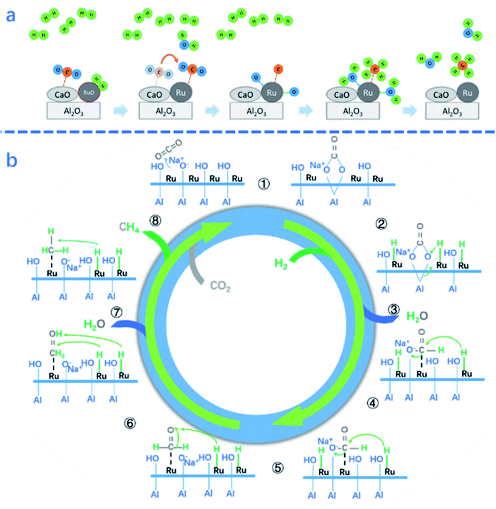 | ||
| Fig. 3 (a) Proposed schematic mechanism of the surface reactions on Ru,CaO/Al2O3 DFMs for CO2 methanation in ICCU.44 (b) Proposed CO2 methanation mechanism over 5%Ru–Na2O/Al2O3 DFMs.59 | ||
It is known that the loading of Ru is closely related to the catalytic performance. Bermejo-López et al.52 proposed that a higher Ru loading in Ru–10%Na2CO3/Al2O3 resulted in an acceptable ICCU performance even at a notably lower temperature (i.e. 310 °C). However, there is an optimum Ru loading for ICCU-methanation. For example, Sun et al.54 reported that 10% Ru/CeO2–MgO showed poorer stability than 5% Ru/CeO2–MgO. It is mainly attributed to the presence of more oxygen vacancies that remained in 5% Ru/CeO2–MgO. Better dispersion of Ru also promotes ICCU-methanation. For example, Melis et al.45 reported that increasing the weight ratio of CaO to Ru promoted CO2 spillover from CaO to Ru sites and then increased the performance of ICCU-methanation.
The distance between the active metals and the adsorbents also affects the performance of ICCU-methanation. Melis et al.45 compared physically mixed 10% Ru/γ-Al2O3 and 10% CaO/γ-Al2O3 with 10% Ru-10% CaO/γ-Al2O3 for ICCU-methanation. The physically mixed DFMs showed a poor ICCU performance (0.12 g-mol CH4/kg DFM) owing to the longer distance between active sites within the DFMs decreasing the effective CO2 spillover. However, Sun et al.53 reported different conclusions by comparing physically mixed Ni/CeO2–CaO with impregnated Ni/CeCaO DFMs. The longer distance between Ni and CaO prevented the coverage of Ni from the formation of CaCO3. Furthermore, the introduction of a CeO2 support would promote the dispersion of Ni and increase the performance of ICCU-methanation.
The addition of additives could promote the catalytic performance of DFMs for ICCU-methanation. For example, Stefano et al.62 introduced various alkali metals (Li, Na, and K carbonates vs. nitrates) into 1% Ru/Al2O3 DFMs and found that both the capture capacity of CO2 and activity of methanation were enhanced via doping with Li (nitrates), which could react with Al2O3 to form a mixed spinel phase.
Investigating the catalytic mechanism helps to develop DFMs for ICCU-methanation. The mechanism and key intermediates of CH4 formation from the ICCU process were studied by in situ diffuse reflectance infrared fourier transform spectroscopy (DRIFTS).59 Proaño et al.59 investigated the two steps of ICCU-methanation, including CO2 adsorption and hydrogenation, over 5% Ru–6.1% Na2O/Al2O3 DFMs. The authors found that CO2 absorbed on the AlO−–Na+ species formed bidentate carbonates (i.e. 1st step in Fig. 3b), and then the adsorbed bicarbonates and bidentate carbonates spilled over onto the Ru-support interface during the CO2 methanation process, with formates as reaction intermediates (i.e. 2nd and 3rd steps in Fig. 3b), which is consistent with the results reported by Sun et al.54 In addition to the adsorbent, Ru as the catalytic site also showed the capacity of CO2 adsorption,44,59 generating carbonyl groups.54
A lot of research has been conducted on the production of CH4 by ICCU, but there is no valuable economic evaluation research in this field yet. However, ICCU-methanation can be combined with renewable H2, and it still has a very broad prospect as integrated hydrogen storage and carbon-neutral solution.
3. Progress in integrated CO2 capture and DRM
Compared to CO2, the greenhouse effect of CH4 is 22 times higher. Currently, CH4 is widely used to produce H2 by chemical looping reforming63 or steam methane reforming.64 Dry reforming of methane (DRM) utilizing these two major greenhouse gases, as shown in eqn (2), has received increasing attention in recent years.36,65 In addition to CH4, C2H6 and other low-carbon alkanes could also be used for dry reforming. Integrated CO2 capture and dry reforming (ICCU-DRM) provides a promising solution for utilizing low carbon alkanes accompanied by the reduction of CO2 emissions. Synthesizing liquid fuels or high-value hydrocarbons by Fischer–Tropsch synthesis using the products from the ICCU-DRM process could be a practical route for upgrading alkanes.| CH4 + CO2 = 2CO + 2H2 ΔH298 K = +247 kJ mol−1 | (2) |
3.1 Influence of process parameters on ICCU-DRM
In this section, the influences of process parameters on the performance of ICCU-DRM are reviewed and discussed. As shown in Fig. 4a, there are various side reactions in ICCU-DRM, including CH4 decomposition and the reverse-water-gas shift reaction (RWGS), which would generate coke on the surface of DFMs and affect the ratio of H2/CO in the final product. | ||
| Fig. 4 (a)Gibbs free energy of related reactions in integrated CO2 capture and DRM as a function of temperature.2 (b) Coupled CO2 capture and conversion reactions: molar flow rate of the effluent gas in the first cycle of the coupled CO2 capture–conversion process and schematic description of the main processes occurring in the reactor.1 | ||
Temperature is one of the most effective parameters to influence the balance of DRM and side reactions. Molina-Ramírez et al.66 studied different temperatures (600–700 °C) of ICCU-DRM using a non-supported Ni–Ba bifunctional catalyst. The conversion of CH4 increased with the increase of temperature (11.04% at 600 °C and 18.57% at 700 °C), while the selectivity to CO showed an opposite trend (14.89% at 600 °C and 4.69% at 700 °C). The side reactions, especially CH4 decomposition, are favored at a higher temperature. The ratio of H2/CO increased from 5.7 at 600 °C to 20.4 at 700 °C, which was accompanied by a significant carbon deposition on the surface of the DFMs. By applying dry reforming of ethane, Ahmed et al.67 investigated the influence of reaction temperature on Ni20@(K–Ca)50/(γ-Al2O3)50 over ICCU and found that the yield of syngas continuously increased with increasing temperature. Ethane conversion was positively correlated with temperature and could be fully converted at a higher temperature (>650 °C), while the CO2 conversion equilibrated at ∼65% (>600 °C).
For ICCU-DRM, a higher temperature is not always preferred. Molina-Ramírez et al.66 reported that the optimal temperature of Ni–Ba DFMs for CO2 adsorption is 650 °C (0.37 mmol g−1), capturing 0.23 and 0.13 mmol g−1 CO2 at 600 and 700 °C, respectively. It is suggested that a higher temperature enables the adsorption to approach equilibrium faster, but reduces the adsorption capacity at equilibrium. In terms of the desorption temperature for ICCU-DRM, Kim et al.1 proposed that a reaction temperature of around 720 °C could steadily release CO2. Too fast desorption would cause excessive CO2 release at the initial time of the conversion stage, while slow desorption would decrease the overall efficiency of ICCU-DRM.
Reaction time is another important parameter in ICCU-DRM. For example, Kim et al.1 studied different stages of ICCU through continuous online gas analysis. As shown in Fig. 4b, three reaction stages were proposed: (1) in the pre-breakthrough stage, CO2 and CH4 were almost fully converted, only 0.08% and 0.06% escaped, respectively. The produced syngas had a slightly higher H2/CO ratio (∼1.06![[thin space (1/6-em)]](https://www.rsc.org/images/entities/char_2009.gif) :1) than thermodynamic equilibrium (0.94:1) at 720 °C, probably owing to the decomposition of CH4. (2) The CO yield was gradually decreased due to the reduction of CO2 release, while the H2 yield remained stable during the following ∼18 min, namely the breakthrough stage. (3) The H2 mole flow rate gradually decreased in the post-breakthrough stage due to the deactivation of the catalyst, which was caused by the deposition of carbon generated by CH4 decomposition in the previous stages. Therefore, the ratio of H2/CO in the product can be controlled by adjusting the reaction time at different stages of ICCU-DRM.
:1) than thermodynamic equilibrium (0.94:1) at 720 °C, probably owing to the decomposition of CH4. (2) The CO yield was gradually decreased due to the reduction of CO2 release, while the H2 yield remained stable during the following ∼18 min, namely the breakthrough stage. (3) The H2 mole flow rate gradually decreased in the post-breakthrough stage due to the deactivation of the catalyst, which was caused by the deposition of carbon generated by CH4 decomposition in the previous stages. Therefore, the ratio of H2/CO in the product can be controlled by adjusting the reaction time at different stages of ICCU-DRM.
3.2 Development progress of DFMs for ICCU-DRM
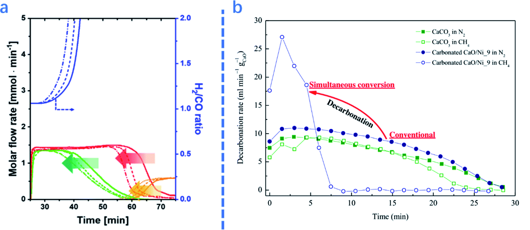 | ||
| Fig. 5 (a): Molar flow rate and H2/CO ratio of the effluent gas as a function of cycle number: (—) 1st, (- - -) 5th, and (–•–) 10th cycles. The arrows highlight the trends with cycle number;1 (b) comparison of decarbonation kinetics as a function of time at 1073 K between CaL methane reforming and separate CaL processes.2 | ||
The presence of catalysts also affects the performance of adsorbents in ICCU-DRM. As shown in Fig. 5b, Tian et al.2 reported that introducing catalysts in adsorbents significantly promoted the decomposition of CaCO3 (∼3 times faster). A similar promotion effect of catalysts on adsorbents was also reported by Ahmed et al.67
Other adsorbents were also applied in ICCU-DRM, however with poor adsorption performance. For example, Molina-Ramírez et al.66 synthesized a Ni–Ba unsupported DFM and obtained 0.232 mmol g−1 capacity of CO2 capture. In addition, MgO is not a suitable adsorbent for ICCU-DRM as Ahmed et al.67 only achieved 0.22 mmol g−1 capture capacity of CO2 using Ni10@(K–Mg)25/(γ-Al2O3)75 DFMs at 650 °C, which was much lower than that achieved by Ca-based adsorbents.
Fe-based catalysts also showed a good performance for ICCU-DRM. For example, Zhao et al.3 demonstrated a Ca–Fe chemical looping reforming process for ICCU. The authors observed the occurrence of the reaction between CH4 and CaCO3 and Fe2O3. As shown in Fig. 6b, in the 1st stage, the rapid full CH4 oxidation reaction occurred and all Fe2O3 was changed into Fe3O4 (eqn (3) and eqn (4)) without CO generation.
 | ||
| Fig. 6 Diagram of the reaction mechanism for the novel Ca–Fe chemicallooping reforming process.3 | ||
In the 2nd stage, the interaction between Fe-based oxygen storage materials and CO2 adsorbents accompanied by the CH4 reforming of CaCO3 (eqn (5) and eqn (6)) achieved pure syngas production. Fe3O4 was gradually transformed into Fe and FeAl2O4 with the grain size change in this stage. Along with further interactions, FeO rather than Fe was detected at the 3rd reaction stage. This might be attributed to the influence of the oxygen sources, including CO2, lattice oxygen from the incompletely reduced Fe-based oxygen storage materials, or even lattice oxygen from the Al2O3 support. In the final stage, there was a reappearance of CaCO3, which suggested that when the spine FeAl2O4 was reformed by methane, the unwanted byproduct CO2 was recaptured by the carbonation reaction and thus utilized. In conclusion, the Ca–Fe DFM could restore its state and activity after oxidation and carbonation in flue gas and showed acceptable cycle stability.
| 12Fe2O3 + CH4 → 8Fe3O4 + CO2 + 2H2O ΔG1173 K = −532.33 kJ mol−1 | (3) |
| 6Fe2O3 + CH4 → 4Fe3O4 + CO2 + 2H2 ΔG1173 K = −300.08 kJ mol−1 | (4) |
| CaCO3 + CH4 → CaO + 2CO + 2H2 ΔG1173 K = −74.96 kJ mol−1 | (5) |
| 3CaCO3 + CH4 → 3CaO + 4CO + 2H2O ΔG1173 K = −84.07 kJ mol−1 | (6) |
Introducing specific additives promotes ICCU-DRM. Ahmed et al.67 proposed that a K-introduced DFM showed better reducibility than a Na-introduced DFM by enhancing catalyst–support interactions. The promotion effect of Ni–Ca interactions was also verified by comparison with that of Ni–Mg DFMs. It was noted that with the introduction of alkaline metals, the ratio of H2/CO was affected. For example, the K-introduced DFM showed a higher H2/CO ratio owing to the higher conversion of dry reforming ethane and other side reactions.
4. Progress in integrated CO2 capture and RWGS
The reverse water gas shift (RWGS) reaction is another important reaction in C1-chemistry, which can connect with the production of valuable hydrocarbons through Fischer–Tropsch using the produced syngas.69,70 As shown in eqn (7), the RWGS reaction is an endothermic process with lower Gibbs energy than DRM. Although more expensive H2 is used, the RWGS process has fewer side reactions than DRM. The integrated CO2 capture and RWGS (ICCU-RWGS) process possesses the potential opportunity to directly produce pure syngas from flue gas.| CO2 + H2 = CO + H2O ΔH298 K = +41.2 kJ mol−1 | (7) |
4.1 Influence of process parameters on ICCU-RWGS
In this section, several key parameters, including temperature, CO2 concentration and the presence of contaminants, are reviewed for ICCU-RWGS. As shown in Fig. 7b, Luis et al.71 reported that a higher temperature improved both CO2 conversion and CO selectivity owing to the endothermic properties of RWGS. A similar trend in relation to the influence of temperature was also reported by Jo et al.43 using Ni/CaO DFMs. Shao et al.72 analyzed the temperature-programmed desorption of ICCU-RWGS using a FexCoyMg10CaO DFM and found that CO could be generated at 550 °C, which was earlier than CO2 release. Within a certain temperature range (<650 °C), operating ICCU-RWGS at a higher temperature could generate more CO due to the release of more CO2. However, too fast CO2 release rate at high temperatures could reduce its conversion to CO. | ||
| Fig. 7 CO2 capture efficiency, CO2 conversion, and CO selectivity as a function of (a) CO2 concentration (5.8–9.5%) at 450 °C and (b) reaction temperature with 5.8% CO2. The gas composition–capture phase: CO2 diluted in nitrogen (ideal condition), CO2 diluted in nitrogen saturated with 4% of water vapour (effect of water), CO2 diluted in nitrogen with 4% of oxygen (effect of oxygen) and CO2 diluted in nitrogen with 5% of oxygen and 4% of water (realistic condition). Gas hourly space velocity (GHSV)-1620 ml gcat−1 h−1. Reduction phase: Pure hydrogen with a GHSV of 3900 ml gcat−1 h−1. The CCR period length was 215 s, i.e. 107.5 s for the CO2 capture and reduction phase.71 | ||
O2 and H2O are present in flue gas and affect the performance of ICCU-RWGS. Luis et al.71 investigated the influence of the presence of O2 or H2O on ICCU-RWGS using FeCrCu/K/hydrotalcite DFMs (Fig. 7a). The realistic conditions resulted in a poorer ICCU-RWGS performance owing to the deactivation of active sites (e.g. by surface oxidation or adsorption). The presence of H2O could suppress ICCU-RWGS by competitively adsorbing CO2 and affect RWGS equilibrium. Compared with the presence of H2O, the existing O2 has a more negative impact on ICCU-RWGS. The presence of O2 would significantly decrease CO2 conversion owing to the oxidation of catalytic sites.
The CO2 concentration could affect not only the performance of CO2 adsorption, but also the following RWGS process. With the increase of CO2 concentration from 5.8% to 9.5%, the efficiency of CO2 capture and CO2 conversion slightly decreased at temperatures under 450 °C, i.e. from 100% to 98% and from 80% to 67%, respectively. In contrast, CO selectivity was increased from 90% to 92%.71
4.2 Development of DFM progress for ICCU-RWGS
In addition, introducing materials with high thermal stability also helps to limit excessive sintering of CaO. Sun et al.73 reported that introducing CeO2 as a physical barrier retarded the sintering of CaO. Similarly, Shao et al.72 achieved impressive cycle stability (no decrease after 10 cycles) by adding MgO into the DFMs.
Apart from the widely used CaO, hydrotalcite could also be a potential adsorbent, due to its structural stability at high temperatures. DFMs using hydrotalcite as an adsorbent showed excellent stability (stable after 750 cycles).71
 | ||
| Fig. 8 CO2 conversion of RWGS39,74,76–88,90–92,94–117 and integrated CO2 capture and RWGS.71–73 | ||
In the existing ICCU-RWGS research work, transition metal-based catalysts have shown excellent catalytic performance. Shao et al.72 applied bimetallic Fe3+/Fe2+ and Co3+/Co2+ redox couples in a hierarchical porous CaO/MgO composite and achieved an excellent ICCU-RWGS performance. The bimetallic couples significantly lowered the electric potential difference of Fe3+/Fe2+ through the newly formed Fermi level in Fe5Co5Mg10CaO, which made the electron spillover easier to improve the catalytic activity. It was suggested that the same content of Fe and Co could achieve optimal ICCU-RWGS performance. The authors also proposed that Fe2+ was the active catalytic site, whereas Co acted as the catalytic promoter in Fe5Co5Mg10CaO DFMs. The catalytic process is as follows: firstly, CO2 was catalytically reduced to CO by magnetite (Fe3O4). Secondly, hematite (Fe2O3) was regenerated by H2 with Co as the promoter. The well-dispersed Fe can ensure the continuous and efficient process of this catalytic process. Luis et al.71 synthesized FeCrCu/K/MgO–Al2O3 DFMs for ICCU-RWGS under realistic conditions, and the key functions of Cu and K were suggested for efficient CO2 reduction and capture, respectively.
Supports can also play key roles in the catalytic process by promoting and stabilizing active catalytic sites. Sun et al.73 synthesized Ni–CeO2/CaO DFMs and achieved almost 100% CO selectivity, 51.8% CO2 conversion and remarkable cycle stability after 20 cycles of ICCU. The oxygen vacancies and interaction between Ni and CeO2 were believed to play key roles in promoting ICCU-RWGS. It was suggested that the formed interaction would effectively retard the agglomeration of NiO.
5. Progress in low temperature ICCU
The widely applied CO2 capture (i.e. MEA adsorption and calcium looping) and utilization (i.e. CO2 methanation and RWGS) consume a large amount of energy for sorbent regeneration and CO2 conversion. To overcome the drawbacks of the above processes, many researchers paid attention to photo-, electronic- and plasma-promoted catalytic processes. The integrated process can achieve promising performance under more mild conditions (ambient temperature and pressure) with the introduction of photo, electronic or plasma energy.The traditional CO2 capture and utilization process can achieve excellent process efficiency. However, it needs either high temperature (>500 °C) or high pressure (>20 bar). Furthermore, these processes required relatively expensive reducing agents (i.e. H2 and CH4) to convert CO2. Alternatively, photo-catalytic reduction of CO2 with H2O has emerged as a promising option.118 Hybrid MgAl(LDO)/TiO2,118 NH2-UiO-66/TiO2,119 Mg(OH)2/CuO/Cu2O,120etc. are applied in integrated CO2 capture and utilization and achieved promising results. Imidazolium ionic liquids, imidazolylidene heterocyclic carbenes, and zeolitic imidazolate frameworks are also commonly used materials to realize this process.33 Integrated CO2 capture and photo-catalytic conversion provide a sustainable solution for CO2 emission reduction and utilization, which faces challenges in the improvement of catalytic efficiency.
The electrocatalytic CO2 reduction reaction (CO2RR) to produce valuable chemicals with renewable energy inputs is an attractive route to convert intermittent green energy sources.121–123 The CO2RR remains a huge challenge due to multiple proton and electron transfer processes and the chemical inertness of CO2 molecules.124 Therefore, many researchers developed various finely designed materials to improve the efficiency of CO2 conversion. For example, Jiang et al.124 applied a wet chemistry and pyrolysis method to synthesize Sb SA/NC and achieved efficient formate production (faradaic efficiency of 94.0% at −0.8 V vs. RHE). Recently, Lee et al.125 achieved an electrochemical upgrade of CO2 from amine capture solution, promising progress in large-scale application of integrated CO2 capture and electrocatalytic conversion. Electrocatalysis has a very high energy utilization efficiency. The possible drawbacks are the high requirements for the purity of the reactants to avoid the poisoning effect of impurities on the catalysts and equipment.126
Non-thermal plasma (NTP) catalyzed CO2 conversion has also become a promising method to significantly reduce the reaction temperature because plasma can activate CO2 at room temperatures and atmospheric pressure.29,32 In addition to DFMs containing adsorbents and catalysts, the membrane reactor is also gaining researchers' attention. Chen et al.127 realized integrated CO2 membrane separation and NTP CO2 conversion with 91.8% carbon capture efficiency and 71.7% carbon utilization efficiency. This integrated process was also verified by Li et al.128 ICCU with NTP can achieve excellent reaction efficiency and scalable CO2 throughput. However, energy consumption related to NTP-ICCU needs to be particularly investigated.
Nowadays, low-temperature ICCU has gradually become a promising direction, and many finely designed materials are used in ICCU under mild conditions and have achieved excellent catalytic performance. CO2 reduction and neutralization should deal with a concentrated CO2 in industry (i.e. power plants and cement factories), which requires high CO2 throughput. High material costs may not be suitable for large-scale processing, and the resistance to impurities in the CO2 sources will also determine the availability of related CCU technologies.
6. Conclusions and prospects
In this paper, we have critically reviewed the state-of-the-art progress in integrated high temperature CO2 capture and catalytic conversion, including CO2 methanation, DRM and RWGS, from the perspective of process parameters and catalytic materials. This process can not only decrease the overall CO2 utilization cost by eliminating CO2 enrichment and transportation, but also achieve outstanding CO2 conversion performance owing to the reducing agent rich conditions. However, there are several research gaps in this field that need to be addressed. For example, comprehensive considerations from the perspective of engineering are needed, including process design, and economic and technical analysis. The energy consumption for high temperature operations is noteworthy. Therefore, developing low-cost materials that can process ICCU at lower temperatures is promising. Furthermore, more research is needed for the development of dual functional catalysts for application in ICCU, including an in-depth understanding of the synergies between catalysts and adsorbents in addition to reaction intermediates.For ICCU-methanation, an intermediate process temperature (∼300 °C) shows better catalytic activity and CH4 selectivity. Ni-based DFMs can achieve excellent ICCU-methanation performance only in the absence of O2. The noble metal-based DFMs can obtain impressive ICCU performance, however, with inevitable high cost. The spillover of CO2 from adsorbents to catalytic sites is a key step for ICCU-methanation, which can be promoted by the interactions between adsorbents and catalysts. More research on the interactions within DFMs is necessary for a better understanding of the ICCU-methanation process and effective catalyst design. Furthermore, an economic evaluation will guide the development of ICCU-methanation.
For ICCU-DRM, a high temperature (>500 °C) is necessary to promote reactions. Therefore, both CaO and Ni are applicable and affordable. The reaction time is a critical parameter to control the coke formation in DFMs and optimize the H2/CO ratio of syngas in ICCU-DRM. The sintering of CaO and active metals at high temperatures is usually the main reason for the decrease of catalytic activity owing to the coverage of active sites and agglomeration of metals. The environmentally unfriendly CO generated from the coke in DFMs in the adsorption step is also worthy of attention.
ICCU-RWGS is a promising integrated process owing to its lower Gibbs energy and excellent selectivity of syngas. The ICCU-RWGS process shows great potential for surpassing the equilibrium limitation of CO2 conversion in traditional RWGS. The interaction among different components within DFMs plays multifunctional roles in ICCU-RWGS, including prohibiting the sintering of adsorbents, dispersing active metals and providing active sites. Apart from the investigation on the interaction within DFMs, the H2/CO ratio of syngas from ICCU-RWGS also deserves more attention.
In conclusion, CO2 capture and in situ catalytic conversion are still in their infancy. Reducing CO2 emissions is not necessarily a high-cost industry. In contrast, it is possible to generate economic benefits through industrial integration. ICCU provides an economic CO2 utilization strategy, which can integrate the abundant research on CO2 capture and conversion and provide a solution for an urgent environmental need. The integration of CO2 capture and utilization can also be expanded to other processes, including producing methanol or other valuable C2+ chemicals. By producing more valuable chemicals, ICCU has the potential to be profitably accompanied by CO2 emission reduction.
Conflicts of interest
There are no conflicts to declare.Acknowledgements
The authors gratefully acknowledge financial support from the China Scholarship Council (reference number: 201906450023). This project has received funding from the European Union's Horizon 2020 research and innovation programme under the Marie Skłodowska-Curie grant agreement No 823745.Notes and references
- S. M. Kim, P. M. Abdala, M. Broda, D. Hosseini, C. Coperet and C. Muller, ACS Catal., 2018, 8, 2815–2823 CrossRef CAS.
- S. Tian, F. Yan, Z. Zhang and J. Jiang, Sci. Adv., 2019, 5, eaav5077 CrossRef CAS PubMed.
- Y. L. Zhao, B. Jin and Z. W. Liang, Ind. Eng. Chem. Res., 2020, 59, 1298–1307 CrossRef CAS.
- W. Gao, S. Liang, R. Wang, Q. Jiang, Y. Zhang, Q. Zheng, B. Xie, C. Y. Toe, X. Zhu and J. Wang, Chem. Soc. Rev., 2020, 8584–8686 RSC.
- S. J. Wang, G. D. Li and C. L. Fang, Renewable Sustainable Energy Rev., 2018, 81, 2144–2159 CrossRef.
- R. N. E. Huaman and T. X. Jun, Renewable Sustainable Energy Rev., 2014, 31, 368–385 CrossRef.
- B. L. Salvi and S. Jindal, SN Appl. Sci., 2019, 1, 20 CrossRef.
- R. Falkner, H. Stephan and J. Vogler, Glob. Policy, 2010, 1, 252–262 CrossRef.
- R. Falkner, Int. Aff., 2016, 92, 1107–1125 CrossRef.
- G. Scheffknecht, L. Al-Makhadmeh, U. Schnell and J. Maier, Int. J. Greenhouse Gas Control, 2011, 5, S16–S35 CrossRef CAS.
- E. I. Koytsoumpa, C. Bergins and E. Kakaras, J. Supercrit. Fluids, 2018, 132, 3–16 CrossRef CAS.
- M. E. Boot-Handford, J. C. Abanades, E. J. Anthony, M. J. Blunt, S. Brandani, N. Mac Dowell, J. R. Fernandez, M. C. Ferrari, R. Gross, J. P. Hallett, R. S. Haszeldine, P. Heptonstall, A. Lyngfelt, Z. Makuch, E. Mangano, R. T. J. Porter, M. Pourkashanian, G. T. Rochelle, N. Shah, J. G. Yao and P. S. Fennell, Energy Environ. Sci., 2014, 7, 130–189 RSC.
- M. D. Aminu, S. A. Nabavi, C. A. Rochelle and V. Manovic, Appl. Energy, 2017, 208, 1389–1419 CrossRef CAS.
- A. Sanna, M. Uibu, G. Caramanna, R. Kuusik and M. M. Maroto-Valer, Chem. Soc. Rev., 2014, 43, 8049–8080 RSC.
- Y. Zheng, W. Q. Zhang, Y. F. Li, J. Chen, B. Yu, J. C. Wang, L. Zhang and J. J. Zhang, Nano Energy, 2017, 40, 512–539 CrossRef CAS.
- M. Bui, C. S. Adjiman, A. Bardow, E. J. Anthony, A. Boston, S. Brown, P. S. Fennell, S. Fuss, A. Galindo, L. A. Hackett, J. P. Hallett, H. J. Herzog, G. Jackson, J. Kemper, S. Krevor, G. C. Maitland, M. Matuszewski, I. S. Metcalfe, C. Petit, G. Puxty, J. Reimer, D. M. Reiner, E. S. Rubin, S. A. Scott, N. Shah, B. Smit, J. P. M. Trusler, P. Webley, J. Wilcox and N. Mac Dowell, Energy Environ. Sci., 2018, 11, 1062–1176 RSC.
- Y. A. Criado, B. Arias and J. C. Abanades, Energy Environ. Sci., 2017, 10, 1994–2004 RSC.
- S. Fakher and A. Imqam, Fuel, 2020, 265 Search PubMed.
- M. van der Spek, S. Roussanaly and E. S. Rubin, Int. J. Greenhouse Gas Control, 2019, 83, 91–104 CrossRef.
- M. Zhao, A. I. Minett and A. T. Harris, Energy Environ. Sci., 2013, 6, 25–40 RSC.
- B. A. Seibel and P. J. Walsh, Science, 2001, 294, 319–320 CrossRef CAS.
- J. C. Abanades, E. S. Rubin, M. Mazzotti and H. J. Herzog, Energy Environ. Sci., 2017, 10, 2491–2499 RSC.
- B. Yao, T. Xiao, O. A. Makgae, X. Jie, S. Gonzalez-Cortes, S. Guan, A. I. Kirkland, J. R. Dilworth, H. A. Al-Megren and S. M. Alshihri, Nat. Commun., 2020, 11, 1–12 Search PubMed.
- R. Sen, A. Goeppert, S. Kar and G. S. Prakash, J. Am. Chem. Soc., 2020, 142, 4544–4549 CrossRef CAS.
- P. Bareschino, E. Mancusi, M. Urciuolo, A. Paulillo, R. Chirone and F. Pepe, Renewable Sustainable Energy Rev., 2020, 130, 12 CrossRef.
- M. Jouny, J.-J. Lv, T. Cheng, B. H. Ko, J.-J. Zhu, W. A. Goddard and F. Jiao, Nat. Chem., 2019, 11, 846–851 CrossRef CAS PubMed.
- H. X. Zhong, J. Wang, Q. Zhang, F. Meng, D. Bao, T. Liu, X. Y. Yang, Z. W. Chang, J. M. Yan and X. B. Zhang, Adv. Sustainable Syst., 2017, 1, 1700020 CrossRef.
- D. Bao, Q. Zhang, F. L. Meng, H. X. Zhong, M. M. Shi, Y. Zhang, J. M. Yan, Q. Jiang and X. B. Zhang, Adv. Mater., 2017, 29, 1604799 CrossRef PubMed.
- M. Moss, D. G. Reed, R. W. Allen and P. Styring, Front. Energy Res., 2017, 5, 20 CrossRef.
- C. Chen, X. Zhu, X. Wen, Y. Zhou, L. Zhou, H. Li, L. Tao, Q. Li, S. Du and T. Liu, Nat. Chem., 2020, 12, 717–724 CrossRef CAS PubMed.
- H. C. Fu, F. You, H. R. Li and L. N. He, Front. Chem., 2019, 7, 15 CrossRef PubMed.
- A. George, B. Shen, M. Craven, Y. Wang, D. Kang, C. Wu and X. Tu, Renewable Sustainable Energy Rev., 2021, 135, 109702 CrossRef CAS.
- S. Wang and X. Wang, Angew. Chem., Int. Ed., 2016, 55, 2308–2320 CrossRef CAS.
- M. A. A. Aziz, A. A. Jalil, S. Triwahyono and A. Ahmad, Green Chem., 2015, 17, 2647–2663 RSC.
- P. Frontera, A. Macario, M. Ferraro and P. Antonucci, Catalysts, 2017, 7, 28 CrossRef.
- D. Pakhare and J. Spivey, Chem. Soc. Rev., 2014, 43, 7813–7837 RSC.
- M. S. Fan, A. Z. Abdullah and S. Bhatia, ChemCatChem, 2009, 1, 192–208 CrossRef CAS.
- X. Su, X. L. Yang, B. Zhao and Y. Q. Huang, J. Energy Chem., 2017, 26, 854–867 CrossRef.
- Y. A. Daza and J. N. Kuhn, RSC Adv., 2016, 6, 49675–49691 RSC.
- R. G. Grim, Z. Huang, M. T. Guarnieri, J. R. Ferrell, L. Tao and J. A. Schaidle, Energy Environ. Sci., 2020, 13, 472–494 RSC.
- A. Bermejo-Lopez, B. Pereda-Ayo, J. A. Gonzalez-Marcos and J. R. Gonzalez-Velasco, J. CO2 Util., 2019, 34, 576–587 CrossRef CAS.
- Z. J. Zhou, N. N. Sun, B. D. Wang, Z. H. Han, S. C. Cao, D. Hu, T. Y. Zhu, Q. Shen and W. Wei, ChemSusChem, 2020, 13, 360–368 CrossRef CAS PubMed.
- S. B. Jo, J. H. Woo, J. H. Lee, T. Y. Kim, H. I. Kang, S. C. Lee and J. C. Kim, Sustainable Energy Fuels, 2020, 4, 4679–4687 RSC.
- Q. H. Zheng, R. Farrauto and A. C. Nguyen, Ind. Eng. Chem. Res., 2016, 55, 6768–6776 CrossRef CAS.
- M. S. Duyar, M. A. A. Treviño and R. J. Farrauto, Appl. Catal., B, 2015, 168–169, 370–376 CrossRef CAS.
- M. S. Duyar, S. X. Wang, M. A. Arellano-Trevino and R. J. Farrauto, J. CO2 Util., 2016, 15, 65–71 CrossRef CAS.
- C. V. Miguel, M. A. Soria, A. Mendes and L. M. Madeira, Chem. Eng. J., 2017, 322, 590–602 CrossRef CAS.
- S. X. Wang, E. T. Schrunk, H. Mahajan and R. J. Farrauto, Catalysts, 2017, 7, 88 CrossRef.
- S. X. Wang, R. J. Farrauto, S. Karp, J. H. Jeon and E. T. Schrunk, J. CO2 Util., 2018, 27, 390–397 CrossRef CAS.
- M. A. Arellano-Trevino, Z. Y. He, M. C. Libby and R. J. Farrauto, J. CO2 Util., 2019, 31, 143–151 CrossRef CAS.
- M. A. Arellano-Trevino, N. Kanani, C. W. Jeong-Potter and R. J. Farrauto, Chem. Eng. J., 2019, 375, 8 CrossRef.
- A. Bermejo-Lopez, B. Pereda-Ayo, J. A. Gonzalez-Marcos and J. R. Gonzalez-Velasco, Appl. Catal., B, 2019, 256, 11 CrossRef.
- H. Sun, Y. Wang, S. Xu, A. I. Osman, G. Stenning, J. Han, S. Sun, D. Rooney, P. T. Williams and F. Wang, Fuel, 2020, 286, 119308 CrossRef.
- H. Sun, Y. Zhang, S. Guan, J. Huang and C. Wu, J. CO2 Util., 2020, 38, 262–272 CrossRef CAS.
- G. Li, P. Xiao, P. A. Webley, J. Zhang and R. Singh, Energy Procedia, 2009, 1, 1123–1130 CrossRef CAS.
- J. Gao, Y. Wang, Y. Ping, D. Hu, G. Xu, F. Gu and F. Su, RSC Adv., 2012, 2, 2358–2368 RSC.
- C. J. Keturakis, F. Ni, M. Spicer, M. G. Beaver, H. S. Caram and I. E. Wachs, ChemSusChem, 2014, 7, 3459–3466 CrossRef CAS.
- Q. Pan, J. Peng, T. Sun, S. Wang and S. Wang, Catal. Commun., 2014, 45, 74–78 CrossRef CAS.
- L. Proano, E. Tello, M. A. Arellano-Trevino, S. X. Wang, R. J. Farrauto and M. Cobo, Appl. Surf. Sci., 2019, 479, 25–30 CrossRef CAS.
- W. Wang and J. L. Gong, Front. Chem. Sci. Eng., 2011, 5, 2–10 CrossRef CAS.
- A. E. Aksoylu, A. N. Akin, Z. İ. Önsan and D. L. Trimm, Appl. Catal., A, 1996, 145, 185–193 CrossRef CAS.
- S. Cimino, F. Boccia and L. Lisi, J. CO2 Util., 2020, 37, 195–203 CrossRef CAS.
- S. Bhavsar and G. Veser, RSC Adv., 2014, 4, 47254–47267 RSC.
- E. Ramirez-Cabrera, A. Atkinson and D. Chadwick, Appl. Catal., B, 2004, 47, 127–131 CrossRef CAS.
- M. Usman, W. Daud and H. F. Abbas, Renewable Sustainable Energy Rev., 2015, 45, 710–744 CrossRef CAS.
- S. Molina-Ramírez, M. Cortés-Reyes, C. Herrera, M. A. Larrubia and L. J. Alemany, J. CO2 Util., 2020, 40 Search PubMed.
- A. Al-Mamoori, A. A. Rownaghi and F. Rezaei, ACS Sustainable Chem. Eng., 2018, 6, 13551–13561 CrossRef CAS.
- J. M. Lavoie, Front. Chem., 2014, 2, 81 Search PubMed.
- M. D. Porosoff, B. Yan and J. G. Chen, Energy Environ. Sci., 2016, 9, 62–73 RSC.
- A. Y. Khodakov, W. Chu and P. Fongarland, Chem. Rev., 2007, 107, 1692–1744 CrossRef CAS.
- L. F. Bobadilla, J. M. Riesco-Garcia, G. Penelas-Perez and A. Urakawa, J. CO2 Util., 2016, 14, 106–111 CrossRef CAS.
- B. Shao, G. Hu, K. A. Alkebsi, G. Ye, X. Lin, W. Du, J. Hu, M. Wang, H. Liu and F. Qian, Energy Environ. Sci., 2021, 2291–2301 RSC.
- H. Sun, J. Wang, J. Zhao, B. Shen, J. Shi, J. Huang and C. Wu, Appl. Catal., B, 2019, 244, 63–75 CrossRef CAS.
- A. Goguet, F. Meunier, J. P. Breen, R. Burch, M. I. Petch and A. F. Ghenciu, J. Catal., 2004, 226, 382–392 CrossRef CAS.
- G. Jacobs and B. H. Davis, Appl. Catal., A, 2005, 284, 31–38 CrossRef CAS.
- G. S. Yablonsky, R. Pilasombat, J. P. Breen, R. Burch and S. Hengrasmee, Chem. Eng. Sci., 2010, 65, 2325–2332 CrossRef CAS.
- S. S. Kim, H. H. Lee and S. C. Hong, Appl. Catal., B, 2012, 119, 100–108 Search PubMed.
- S. S. Kim, K. H. Park and S. C. Hong, Fuel Process. Technol., 2013, 108, 47–54 CrossRef CAS.
- X. D. Chen, X. Su, H. M. Duan, B. L. Liang, Y. Q. Huang and T. Zhang, Catal. Today, 2017, 281, 312–318 CrossRef CAS.
- X. L. Yang, X. Su, X. D. Chen, H. M. Duan, B. L. Liang, Q. G. Liu, X. Y. Liu, Y. J. Ren, Y. Q. Huang and T. Zhang, Appl. Catal., B, 2017, 216, 95–105 CrossRef CAS.
- S. M. Lee, H. Eom and S. S. Kim, Environ. Technol., 2019, 42, 182–192 CrossRef.
- C. Panaritis, M. Edake, M. Couillard, R. Einakchi and E. A. Baranova, J. CO2 Util., 2018, 26, 350–358 CrossRef CAS.
- Y. C. Zhuang, R. Currie, K. B. McAuley and D. S. A. Simakov, Appl. Catal., A, 2019, 575, 74–86 CrossRef CAS.
- W. Benzinger, E. Daymo, M. Hettel, L. Maier, C. Antinori, P. Pfeifer and O. Deutschmann, Chem. Eng. J., 2019, 362, 430–441 CrossRef CAS.
- N. Ishito, K. Hara, K. Nakajima and A. Fukuoka, J. Energy Chem., 2016, 25, 306–310 CrossRef.
- J. C. Matsubu, V. N. Yang and P. Christopher, J. Am. Chem. Soc., 2015, 137, 3076–3084 CrossRef CAS.
- A. G. Kharaji, A. Shariati and M. A. Takassi, Chin. J. Chem. Eng., 2013, 21, 1007–1014 CrossRef CAS.
- D. H. Kim, S. W. Han, H. S. Yoon and Y. D. Kim, J. Ind. Eng. Chem., 2015, 23, 67–71 CrossRef CAS.
- J. A. Loiland, M. J. Wulfers, N. S. Marinkovic and R. F. Lobo, Catal. Sci. Technol., 2016, 6, 5267–5279 RSC.
- L. Pastor-Perez, M. Shah, E. le Sache and T. R. Reina, Catalysts, 2018, 8, 608 CrossRef.
- B. Lu and K. Kawamoto, J. Environ. Chem. Eng., 2013, 1, 300–309 CrossRef CAS.
- L. H. Wang, H. Liu, Y. Liu, Y. Chen and S. Q. Yang, J. Rare Earths, 2013, 31, 969–974 CrossRef CAS.
- L. H. Wang, H. Liu, Y. Liu, Y. Chen and S. Q. Yang, J. Rare Earths, 2013, 31, 559–564 CrossRef CAS.
- P. C. Zonetti, S. Letichevsky, A. B. Gaspar, E. F. Sousa-Aguiar and L. G. Appel, Appl. Catal., A, 2014, 475, 48–54 CrossRef CAS.
- M. Lortie, R. Isaifan, Y. Liu and S. Mommers, Int. J. Chem. Eng., 2015, 2015, 750689 Search PubMed.
- M. Lortie and R. J. Isaifan, J. Catal., 2015, 2015, 1–9 Search PubMed.
- C. A. Galvan, J. Schumann, M. Behrens, J. L. G. Fierro, R. Schlogl and E. Frei, Appl. Catal., B, 2016, 195, 104–111 CrossRef.
- X. Zhang, X. B. Zhu, L. L. Lin, S. Y. Yao, M. T. Zhang, X. Liu, X. P. Wang, Y. W. Li, C. Shi and D. Ma, ACS Catal., 2017, 7, 912–918 CrossRef CAS.
- G. L. Zhou, B. C. Dai, H. M. Xie, G. Z. Zhang, K. Xiong and X. X. Zheng, J. CO2 Util., 2017, 21, 292–301 CrossRef CAS.
- L. H. Wang, H. Liu, Y. Chen and S. Q. Yang, Int. J. Hydrogen Energy, 2017, 42, 3682–3689 CrossRef CAS.
- Y. L. Shen, Z. Cao and Z. H. Xiao, Catalysts, 2019, 9, 423 CrossRef CAS.
- L. H. Wang and H. Liu, Catal. Today, 2018, 316, 155–161 CrossRef CAS.
- B. L. Liang, H. M. Duan, X. Su, X. D. Chen, Y. Q. Huang, X. W. Chen, J. J. Delgado and T. Zhang, Catal. Today, 2017, 281, 319–326 CrossRef CAS.
- Z. S. Fishman, Y. L. He, K. R. Yang, A. W. Lounsbury, J. Q. Zhu, T. M. Tran, J. B. Zimmerman, V. S. Batista and L. D. Pfefferle, Nanoscale, 2017, 9, 12984–12995 RSC.
- J. A. Loiland, M. J. Wulfers, N. S. Marinkovic and R. F. Lobo, Catal. Sci. Technol., 2016, 6, 5267–5279 RSC.
- L. Pastor-Perez, F. Baibars, E. Le Sache, H. Arellano-Garcia, S. Gu and T. R. Reina, J. CO2 Util., 2017, 21, 423–428 CrossRef CAS.
- A. Ranjbar, A. Irankhah and S. F. Aghamiri, J. Environ. Chem. Eng., 2018, 6, 4945–4952 CrossRef CAS.
- A. M. Bahmanpour, F. Heroguel, M. Kilic, C. J. Baranowski, L. Artiglia, U. Rothlisberger, J. S. Luterbacher and O. Krocher, ACS Catal., 2019, 9, 6243–6251 CrossRef CAS.
- F. M. Sun, C. F. Yan, Z. D. Wang, C. Q. Guo and S. L. Huang, Int. J. Hydrogen Energy, 2015, 40, 15985–15993 CrossRef CAS.
- N. Nityashree, C. A. H. Price, L. Pastor-Perez, G. V. Manohara, S. Garcia, M. M. Maroto-Valer and T. R. Reina, Appl. Catal., B, 2020, 261 Search PubMed.
- L. Wang, H. Liu, Y. Chen, R. Zhang and S. Yang, Chem. Lett., 2013, 42, 682–683 CrossRef CAS.
- Q. D. Sun, J. Y. Ye, C. J. Liu and Q. F. Ge, Greenhouse Gases: Sci. Technol., 2014, 4, 140–144 CrossRef CAS.
- Y. L. He, K. R. Yang, Z. W. Yu, Z. S. Fishman, L. A. Achola, Z. M. Tobin, J. A. Heinlein, S. Hu, S. L. Suib, V. S. Batista and L. D. Pfefferle, Nanoscale, 2019, 11, 16677–16688 RSC.
- W. Wang, Y. Zhang, Z. Y. Wang, J. M. Yan, Q. F. Ge and C. J. Liu, Catal. Today, 2016, 259, 402–408 CrossRef CAS.
- Q. Zhang, L. Pastor-Perez, W. Jin, S. Gu and T. R. Reina, Appl. Catal., B, 2019, 244, 889–898 CrossRef CAS.
- F. G. Baddour, E. J. Roberts, A. T. To, L. Wang, S. E. Habas, D. A. Ruddy, N. M. Bedford, J. Wright, C. P. Nash, J. A. Schaidle, R. L. Brutchey and N. Malmstadt, J. Am. Chem. Soc., 2020, 142, 1010–1019 CrossRef CAS PubMed.
- J. R. Morse, M. Juneau, J. W. Baldwin, M. D. Porosoff and H. D. Willauer, J. CO2 Util., 2020, 35, 38–46 CrossRef CAS.
- L. Liu, C. Zhao, J. Xu and Y. Li, Appl. Catal., B, 2015, 179, 489–499 CrossRef CAS.
- A. Crake, K. C. Christoforidis, A. Kafizas, S. Zafeiratos and C. Petit, Appl. Catal., B, 2017, 210, 131–140 CrossRef CAS.
- M. Flores-Flores, E. Luévano-Hipólito, L. M. Torres-Martínez and T.-O. Do, Mater. Chem. Phys., 2019, 227, 90–97 CrossRef CAS.
- X. Zhao, L. Du, B. You and Y. Sun, Catal. Sci. Technol., 2020, 10, 2711–2720 RSC.
- K. Liu, J. Wang, M. Shi, J. Yan and Q. Jiang, Adv. Energy Mater., 2019, 9, 1900276 CrossRef.
- K.-H. Liu, H.-X. Zhong, X.-Y. Yang, D. Bao, F.-L. Meng, J.-M. Yan and X.-B. Zhang, Green Chem., 2017, 19, 4284–4288 RSC.
- Z. Jiang, T. Wang, J. Pei, H. Shang, D. Zhou, H. Li, J. Dong, Y. Wang, R. Cao and Z. Zhuang, Energy Environ. Sci., 2020, 13, 2856–2863 RSC.
- G. Lee, Y. C. Li, J.-Y. Kim, T. Peng, D.-H. Nam, A. S. Rasouli, F. Li, M. Luo, A. H. Ip and Y.-C. Joo, Nat. Energy, 2021, 6, 46–53 CrossRef CAS.
- S. M. Tan and M. Pumera, ACS Nano, 2019, 13, 2681–2728 CrossRef CAS PubMed.
- H. Chen, Y. Mu, C. Hardacre and X. Fan, Ind. Eng. Chem. Res., 2020, 59, 8202–8211 CrossRef CAS.
- S. Li, M. Ongis, G. Manzolini and F. Gallucci, Chem. Eng. J., 2021, 410, 128335 CrossRef CAS.
| This journal is © The Royal Society of Chemistry 2021 |