
 Open Access Article
 This Open Access Article is licensed under a
 Creative Commons Attribution 3.0 Unported Licence
Rapid formation and real-time observation of micron-sized conjugated nanofibers with tunable lengths and widths in 20 minutes by living crystallization-driven self-assembly†
Sanghee
Yang
 and
Tae-Lim
Choi
*
and
Tae-Lim
Choi
*
Department of Chemistry, Seoul National University, Seoul 08826, Korea. E-mail: tlc@snu.ac.kr
First published on 29th July 2020
Abstract
Preparing well-defined semiconducting nanostructures from conjugated polymers is of paramount interest for organic optoelectronic devices. Several studies have demonstrated excellent structural and size control from block copolymers (BCPs) containing non-conjugated blocks via crystallization-driven self-assembly (CDSA); however, the precise control of their size and shape remains a challenge due to their poor solubility, causing rapid and uncontrolled aggregation. This study presents a new type of fully conjugated BCP comprising two polyacetylene derivatives termed poly(cyclopentenylene-vinylene) to prepare semiconducting 1D nanofibers. Interestingly, the widths of nanofibers were tuned from 12 to 32 nm based on the contour lengths of their crystalline core blocks. Their lengths could also be controlled from 48 nm to 4.7 μm using the living CDSA. Monitoring of the growth kinetics of the living CDSA revealed the formation of micron-sized 1D nanofibers in less than 20 min. The rapid CDSA enabled us to watch real-time growth using confocal fluorescence microscopy.
Introduction
Conductive molecules are highly advantageous for sensors, functional coatings, and electronic devices.1–4 Among them, conjugated polymers have gained enormous attention due to their advantageous physical properties including their low weight and flexibility.5–7 For example, poly(3-hexylthiophene) (P3HT),8–10 poly(para-phenylenevinylene) (PPV),11 and polyfluorene (PF)12 have been widely used in various device applications. Notably, several reports have highlighted the important relationship between the performance of electronic materials and their nanostructures.13–17 Therefore, constructing nanostructures by using polymer self-assembly to enable precise control on size and shape has become important for device applications.16,17There have been numerous studies on the control of polymeric nanostructures over decades. Many uniform nanostructures have been created using various amphiphilic block copolymers (BCPs) with differing solubilities.18–20 More recently, pioneered by Ian Manners group, an ingenious method termed Crystallization-Driven Self-Assembly (CDSA) was developed. The CDSA method enables the control of the nanostructure with excellent precision.21–31 Many BCPs containing semicrystalline polymers such as polyferrocenylsilane (PFS),21–23 poly(ε-caprolactone) (PCL),24,25 polyethylene (PE),26,27 and polylactide (PLA)28,29 have been successful in forming various uniform nanostructures from 0D-micelle to 3D-supermicelles via CDSA. Despite excellent structural control, the CDSA method has one drawback; it generally takes several hours to days for complete assembly. To broaden the utility of these nanostructures, conjugated oligomers and polymers have been used to form uniform nanostructures via this CDSA method.30–34 However, this strategy may be complicated and challenging due to the strong π–π interaction among conjugated polymers. This reduces their solubility leading to easy aggregation, and disrupting controlled self-assembly. Whilst this issue may be resolved by synthesizing BCPs containing highly soluble non-conjugating shells,33,34 this insulating block would inevitably limit the potential of the resulting partially semiconducting nanostructures as electronic materials.
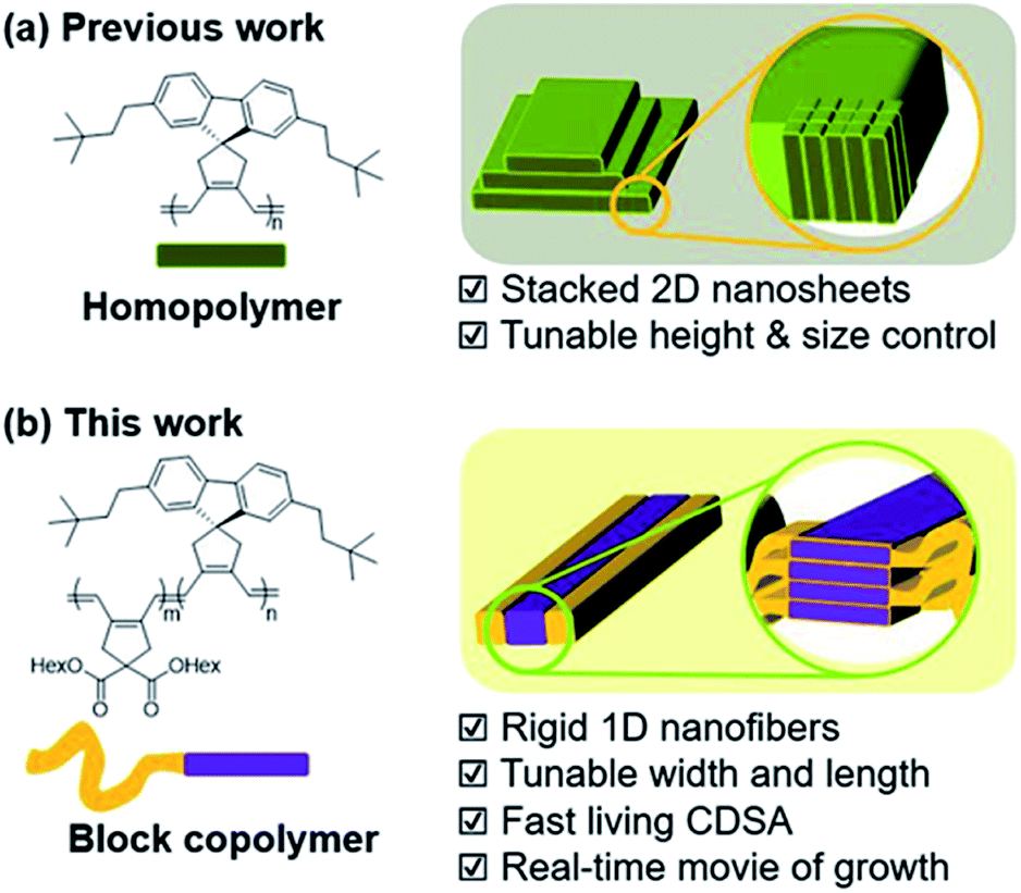
To accelerate the self-assembly process and produce nanostructures more efficiently, a one-pot technique named Polymerization-Induced CDSA (PI-CDSA) was developed where CDSA successful occurred during or after the polymerization.35–37 For the spontaneous formation of the conjugated nanoparticles, we have developed another strategy termed In situ Nanoparticlization of Conjugated Polymers (INCP).38–42 INCP is a process whereby insoluble conjugated polymers are intentionally introduced as the second block. During the synthesis of BCPs, the strong π–π interaction induces spontaneous nanoparticlization, producing semiconducting nanostructures without post-treatment.38–40 A recent study reported large 2D structures from crystalline poly(cyclopentenylene-vinylene) (PCPV) consisting of fluorene and bulky side chains such as neohexyl and silyl groups. Interestingly, the height of the individual 2D sheets was determined by the degree of polymerization (DP) of these homopolymers as their rigid PCPV backbones were self-assembled side-by-side without chain-folding (Scheme 1a).41,42
 | ||
| Scheme 1 New strategy to prepare 1D nanofibers with tunable widths and lengths via rapid self-assembly. | ||
Despite the lack of precise control over the nanostructures, this crystalline PCPV showed potential and its expansion to BCP microstructures may provide insights on achieving higher control of the nanostructures. Herein, we report the formation of well-defined semiconducting 1D nanofibers from BCPs having the PCPV as the core block and another PCPV as a soluble shell block.43 The width of the nanofibers was precisely controlled by the DP of the core block due to the living cyclopolymerization, and the length was controlled via the living CDSA. These two living processes led to not only narrow dispersity of width and length, but also the successful formation of block comicelles (Scheme 1b). Interestingly, this CDSA occurred rapidly, taking 10 min to reach micron-sized lengths, thereby allowing direct visualization of this self-assembly growth using confocal laser optical microscopy.
Results and discussion
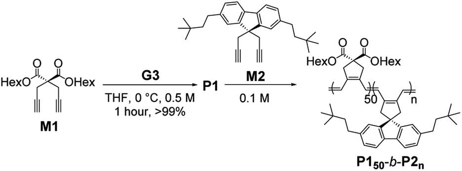
To prepare uniform nanostructures, we synthesized fully conjugated BCPs consisting of the first PCPV block with soluble dihexyl side-chains (M1) and the crystalline second block from M2. To minimize dispersities, various BCPs (with the fixed [M1]/[I] ratio of 50) were polymerized in tetrahydrofuran (THF) at 0 °C using the third-generation Grubbs catalyst (G3).44 After the completion of polymerizations, the reactions were quenched by excess ethyl vinyl ether and the polymers were isolated by precipitation in methanol at 25 °C. Six P150-b-P2ns were prepared with [M2]/[I] ratios from 10 to 66 in excellent isolated yields (Table 1).|
|
||||||
|---|---|---|---|---|---|---|
| Entry | [M1]![[thin space (1/6-em)]](https://www.rsc.org/images/entities/char_2009.gif) :[M2]:[cat] :[M2]:[cat] |
Time | Conv.a (M2) | Yield (%) | M n , (kDa) | Đ , |
| a Calculated by 1H NMR analysis in CDCl3 before precipitation. b Determined by chloroform SEC, calibrated using polystyrene standards. c Determined by AF4 fractograms in chloroform using 0.205 as a dn/dc value. | ||||||
| 1 | 50:10:1 |
2.5 h | >99% | 91 | 23.3b | 1.15b |
| 2 | 50:22:1 |
4 h | >99% | 98 | 38.6b | 1.10b |
| 3 | 50:33:1 |
6 h | >99% | 90 | 47.4b | 1.13b |
| 4 | 50:44:1 |
8 h | >99% | 95 | 10440c |
1.56c |
| 5 | 50:55:1 |
9 h | >99% | 92 | 70350c |
1.26c |
| 6 | 50:66:1 |
11 h | >99% | 92 | 115800c |
1.13c |
We characterized the purified BCPs by 1H nuclear magnetic resonance (NMR) spectroscopy to get some clues about spontaneous self-assembly. For P150-b-P210 and P150-b-P222, signals from both blocks were observed with expected integrations from the feed ratios, indicating low degrees of aggregation in chloroform. However, as the DP of P2 increased to 33, signals for the P2 block were only 28% of that expected from the feed ratio. The integration values further decreased, reaching a minimum of 11% for P150-b-P266 despite the full conversion of M2 (Fig. S1 and S2†).41 This phenomenon agrees well with the previous investigation supporting for the INCP mechanism where longer BCPs spontaneously formed more crystalline cores which then, were not detectable in 1H NMR analysis.38–40,45 To better characterize the BCPs by NMR, we attempted various deuterated solvents such as benzene, 1,4-dioxane, chlorobenzene, and o-dichlorobenzene to dissolve both blocks, but still chloroform was the best solvent for the BCPs (Fig. S3 and S4†). Fortunately, with 1H NMR analysis at 47 °C in chloroform, more quantitative analysis was possible for P150-b-P233 and P150-b-P244 due to better solubility of P2 at the higher temperature (Fig. S5†). More definitive support for INCP was provided by dynamic light scattering (DLS) analysis which gives hydrodynamic diameters (Dh, these values should be treated as qualitative estimation). When all BCPs were dissolved in 1 g L−1 chloroform, large Dh from 58 nm for P150-b-P233 to 346 nm for P150-b-P266 were observed in accordance with the 1H NMR analysis, and these Dh values were retained even at 0.0001 g L−1 (Fig. 1a and S6†). The direct indication of successful INCP using P150-b-P266 was obtained from the TEM imaging, DLS, and UV-Vis analysis of the in situ sample from the reaction solution (Fig. S7†). Due to the INCP, we could only measure the molecular weight (Mn) of smaller BCPs (for P150-b-P210: 23.3 kDa, P150-b-P222: 38.6 kDa, and P150-b-P233: 47.4 kDa) by chloroform size-exclusion chromatography (SEC). This linear increase in Mns and dispersities (Đ) lower than 1.15 supported successful living cyclopolymerization. Fortunately, the Mns of strongly aggregated larger BCPs could be estimated using an advanced technique known as asymmetric flow field-flow fractionation (AF4) analysis to determine Mn up to 115 MDa, supporting in situ self-assembly (Table 1 entries 4 to 6, and Fig. S8†).46,47
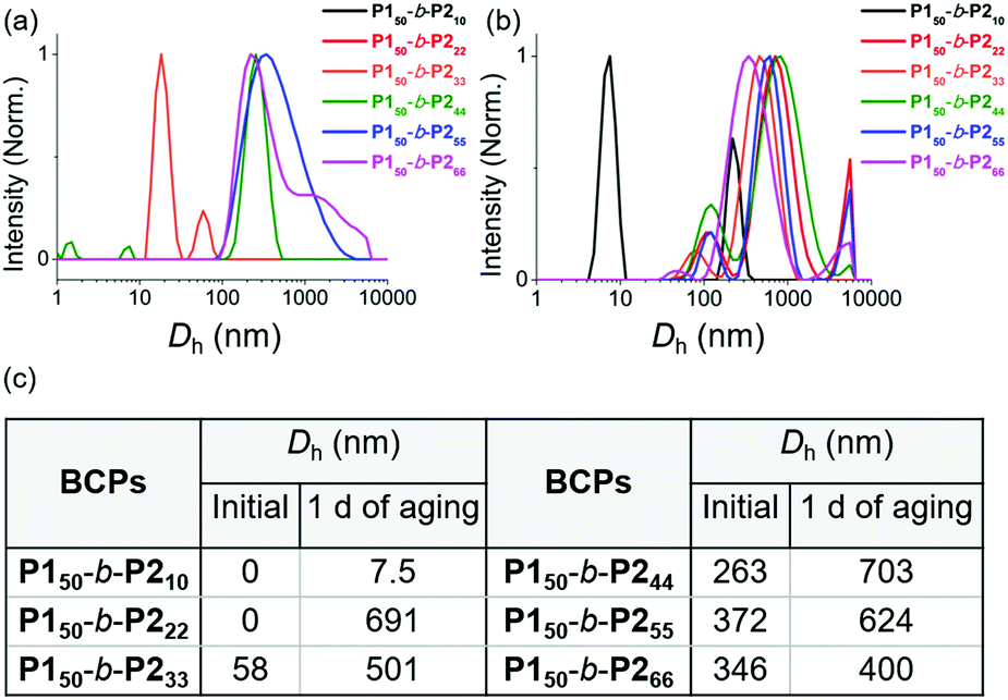 | ||
| Fig. 1 DLS profiles of BCPs solutions (1 g L−1 chloroform) (a) without aging and (b) after 1 day of aging at 25 °C. (c) A table of Dh values of the DLS profiles in (a) and (b). | ||
To further promote self-assembly, we aged BCP solutions (1 g L−1 chloroform) at 25 °C for 1 d, and found an overall increase in Dh, up to 700 nm under identical conditions, except for P150-b-P210 (Fig. 1b and c).48 The BCP having the shortest core block of P210 was still in an unimeric state due to its low crystallinity. A further decrease in the signals for the core block P2via the 1H NMR spectra was also observed. The integration values for P2 in P150-b-P222 decreased from 100 to 74% and, for P150-b-P244–66, these signals were barely observable, indicating quantitative self-assembly in the absence of unimers (Fig. S9†). The UV-Vis analysis of these conjugated BCPs showed much stronger vibronic peaks at 595 nm indicating the formation of more ordered structures (Fig. S10–S12†). However, 1H NMR and DLS analysis showed that the initial BCPs in 1 g L−1 dichloromethane (DCM) solution were already undergoing self-assembly even without aging. This more facile and rapid self-assembly may be due to the lower solubility of P2 in DCM than in chloroform leading to more rapid crystallization (Fig. S13†).
Atomic force microscopy (AFM) imaging without aging was undertaken to visualize these structures. We observed spontaneous formation of 1D nanofibers of BCPsvia INCP, with the exception of P150-b-P222 which required an aging time of 1 h or longer (Fig. 2a–f and S14†). After aging, the length of the 1D nanofibers from P150-b-P222 grew to a maximum of greater than 20 μm, with no branching (Fig. 2b and S15†). Although their heights ranged from 3.6 to 5.5 nm without a certain trend independent of the DP of P2, their widths were observed to roughly increase in proportion to the DP of P2 (Fig. S16†). Even with dilution from 1 to 0.05 g L−1, this width trend continued despite the reduction of their lengths to approximately 1 μm (Fig. S17†). With high magnification AFM images of height and phase modes, the core could be distinguished from the shell to show that the crystalline P2 block was taller and denser than the outer P1 block (Fig. 2g and h).
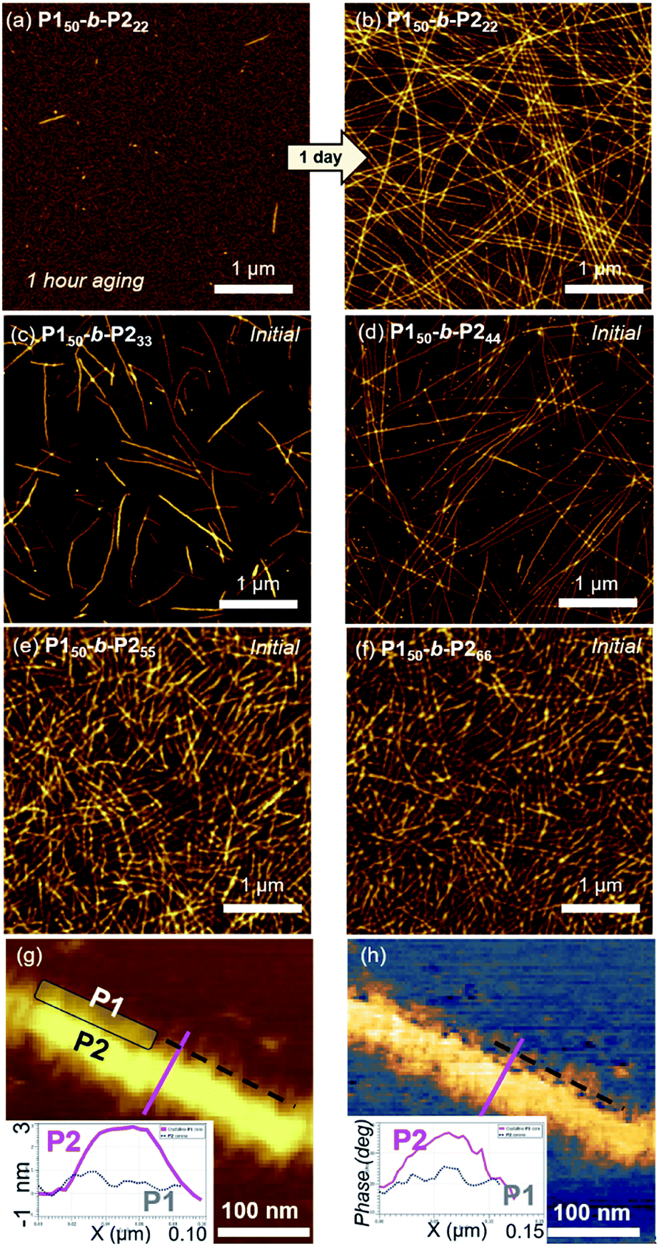 | ||
| Fig. 2 AFM images obtained from 1 g L−1 chloroform solutions of (a) P150-b-P222 after 1 h, and (b) after 1 d aging at 25 °C, (c) P150-b-P233, (d) P150-b-P244, (e) P150-b-P255, and (f) P150-b-P266 without aging. The higher magnification of (g) height, and (h) phase images of the 1D nanofibers from P150-b-P255. | ||
To attain more precise information on width, transmission electron microscopy (TEM) imaging was used. TEM images showed the long fibers with high rigidity without aging, with the exception of P150-b-P222 (Fig. 3a–f and S18†). Without staining, vivid visualization of the electron dense crystalline P2 core was possible, and their measured widths showed a linear increase from 12 to 27 nm, according to an increase of the DP of P2 from 22 to 66 with width dispersities (Ww/Wn) less than 1.02 (Fig. S18c and S19–S21†). In contrast to a previous study on self-assembly of homopolymer of P2, where the DP of the polymer matched well with the height of 2D nanosheets (Scheme 1a), in this study, the width of the 1D nanofibers was well matched to the theoretically estimated contour length of the P2 block (Fig. 3g, see S22 and Table S1† for calculation of the contour lengths by MM2 computational method). Staining using RuO4 vapour also enabled the detection of the flexible P1 block, and measurement of the full width of the 1D nanofibers including the shell demonstrated the presence of thicker fibers from 21 to 35 nm (Fig. 3h and S23†).49
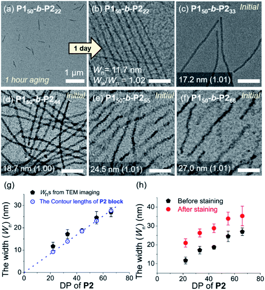 | ||
| Fig. 3 TEM images obtained from 1 g L−1 chloroform solutions of (a) P150-b-P222 after 1 h, and (b) after 1 d aging at 25 °C, (c) P150-b-P233, (d) P150-b-P244, (e) P150-b-P255, and (f) P150-b-P266 without aging (scale bar for (b)–(f), 200 nm). Plots of the DP of P2versus (g) average width (Wn) of the core of the 1D nanofibers compared to the theoretical length of the fully stretched P2 block (a dotted line, Fig. S22†), and (h) Wn after staining with RuO4 vapour. | ||
To investigate the crystallinity of the BCPs and their 1D nanofibers in detail, film X-ray diffraction (FXRD) analysis was conducted on P150-b-P222. A sharp peak was observed at a d-spacing of 16.9 Å originating from P2, a much weaker peak at d-spacing of 13.8 Å was produced from P1, and broad peaks between 4 Å and 8 Å were observed (Fig. 4a and S24†). The P1 signal disappeared in the aged sample of P150-b-P222 and other samples of BCPs having longer P2 block. This indicates that the crystallinity of the P2 block dominated the formation of the 1D nanofibers, and the P1 block formed mostly amorphous structure in the self-assembled nanofibers.41 We also directly observed the crystalline array of the 1D nanofibers from the electron diffraction patterns by selected area electron diffraction (SAED) analysis and fast Fourier transform (FFT) analysis of the high-resolution TEM (HR-TEM) images (Fig. 4b–d and S25†). The SAED showed one d-spacing at 5.0 Å along the longitudinal direction of the 1D nanofibers and another at 4.2 Å in the orthogonal direction. Additionally, spots at 16.1 Å along the longitudinal direction of the 1D nanofibers were obtained by FFT analysis of the HR-TEM. Based on these diffraction patterns and previous findings on the orthorhombic crystal lattice of the P2 homopolymer, we assigned 16.1 Å as a d-spacing in the (200) plane and 4.2 Å in the (002) plane. The fact that the P2 block forms the core by lying down on the c axis, is consistent with the average widths of the core matching the contour lengths of P2 (Fig. 3g and 4e, f).43
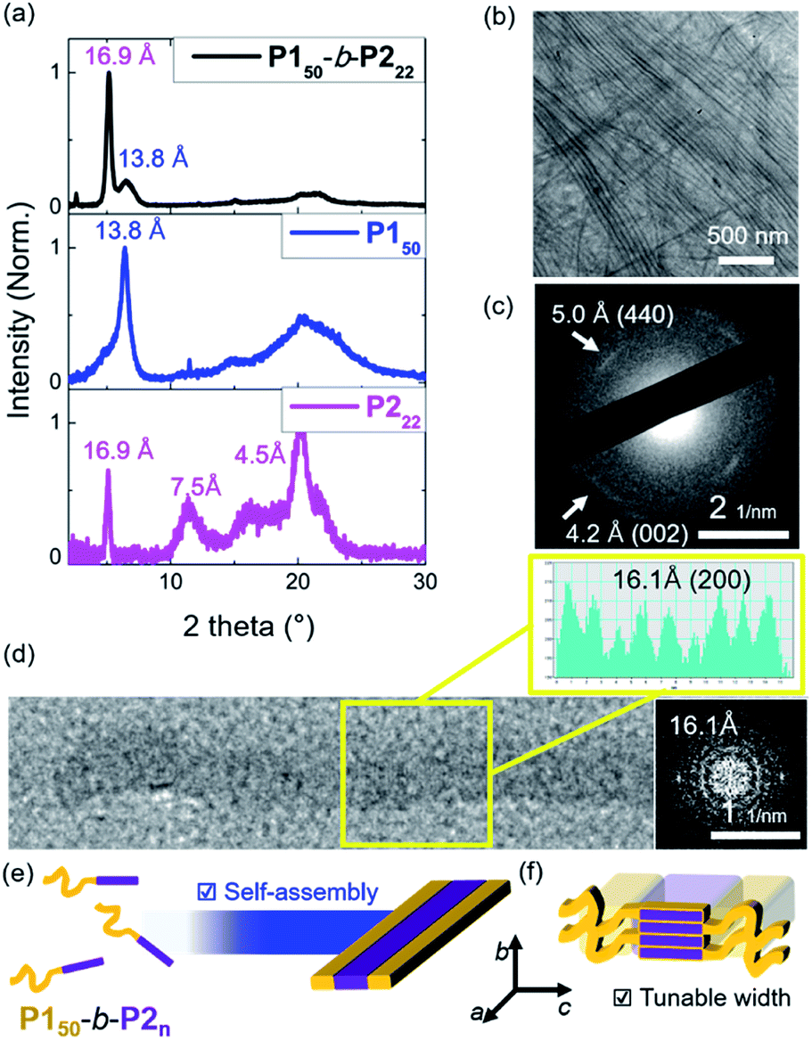 | ||
| Fig. 4 (a) Film XRD plots of the 1D nanofibers from the 10 g L−1 chloroform solution of the P150-b-P222, homopolymers of the P150 and P222. (b) HR-TEM image of the nanofiber bundles and (c) its SAED image showing d-spacings at 5.0 Å and 4.2 Å. (d) A HR-TEM image of a single 1D nanofiber with an additional cross-sectional histogram, and its diffraction pattern showing d-spacing of 16.1 Å. Schematic showing (e) self-assembly of 1D nanofibers, and (f) the detailed orthorhombic crystal array of the core P2 block. | ||
As the width of the 1D nanofibers could be precisely controlled, we attempted to control their lengths by using the living CDSA; epitaxial growth from the uniform seed through the addition of unimers. Fortunately, after sonicating 0.1 g L−1 chloroform solution of long nanofibers from P150-b-P222 for 30 s using an ultrasonicator (11.8 W cm−2) at 0 °C, we obtained a seed solution with an average length (Ln) of 60.3 nm and a relatively narrow length distribution (Lw/Ln = 1.18, characterized by TEM) (Fig. S26†). Then, 10 g L−1 chloroform solution of unimers (before aging), was added to the seed solution at unimer-to-seed (U/S) ratios from 1 to 10. After 1 h of aging at 25 °C, the Dh from DLS analysis increased gradually and more definitively, Ln from TEM imaging increased linearly according to the U/S ratio. However, the 1D nanofibers continued to elongate by doubling in length after 5 h (Fig. S27, S28a and b†). Even with U/S ratios of 1, or more definitively, even without added unimers, the nanofibers became longer than 10 μm after 1 d of aging (Fig. S28c and d†). These results indicated that fiber-to-fiber assembly occurred between their sticky ends even after the completion of the initial seed-to-unimer assembly (or seeded growth), thereby resulting in undesirable end-to-end coupling in chloroform.50–52 Presumably, the adhesive unimers could be generated by the dynamic exchange between the nanofiber and unimer to promote the end-to-end assembly.53 To date, end-to-end coupling was reported to be much slower than seeded growth,50 but in this case, it occurred readily, even at −20 °C (Fig. S28e and f†).
Alternatively, we prepared a seed-solution of P150-b-P222 in 0.1 g L−1 DCM by sonicating for 2 min (Ln of 48.2 nm, Dh of 62.1 nm, and Lw/Ln = 1.13), to achieve lower solubility of the seeds in DCM in order to prevent the formation of sticky ends and thereby suppress end-to-end coupling (Fig. 5a). Subsequently, the same unimer solution of P150-b-P222 at 10 g L−1 in chloroform was added at various temperatures with U/S ratios 5. This resulted in successful seeded growth at 10 °C to form 1D nanofibers (Ln = 188.0 nm, Lw/Ln = 1.11), whose length remained uniform even after 13 h at 10 °C (Fig. S29†). We attempted this for the living CDSA under the same conditions, at various U/S ratios of 2, 5, 10, 20, and 40. Following 4 h of aging, their Ln values linearly increased from 100.7 to 972.3 nm according to the U/S ratios (Fig. 5b and c). The low-magnified TEM images show that the length dispersity was less than 1.15 indicating successful living CDSA. Notably, measured Ln seems to be substantially shorter than the theoretical lengths predicted based on the U/S ratio. This may be due to competitive homogeneous nucleation occurring simultaneously with the seeded-growth, because the solubility of the P2 block became slightly lower in DCM.54,55 The living CDSA was also qualitatively supported by DLS analysis, where their Dh values gradually increased with higher U/S ratios (Fig. 5d). These Dh values also remained fairly constant during aging for a week at both 10 and 25 °C, showing high stability in solution without end-to end coupling (Fig. 5e and S30†).
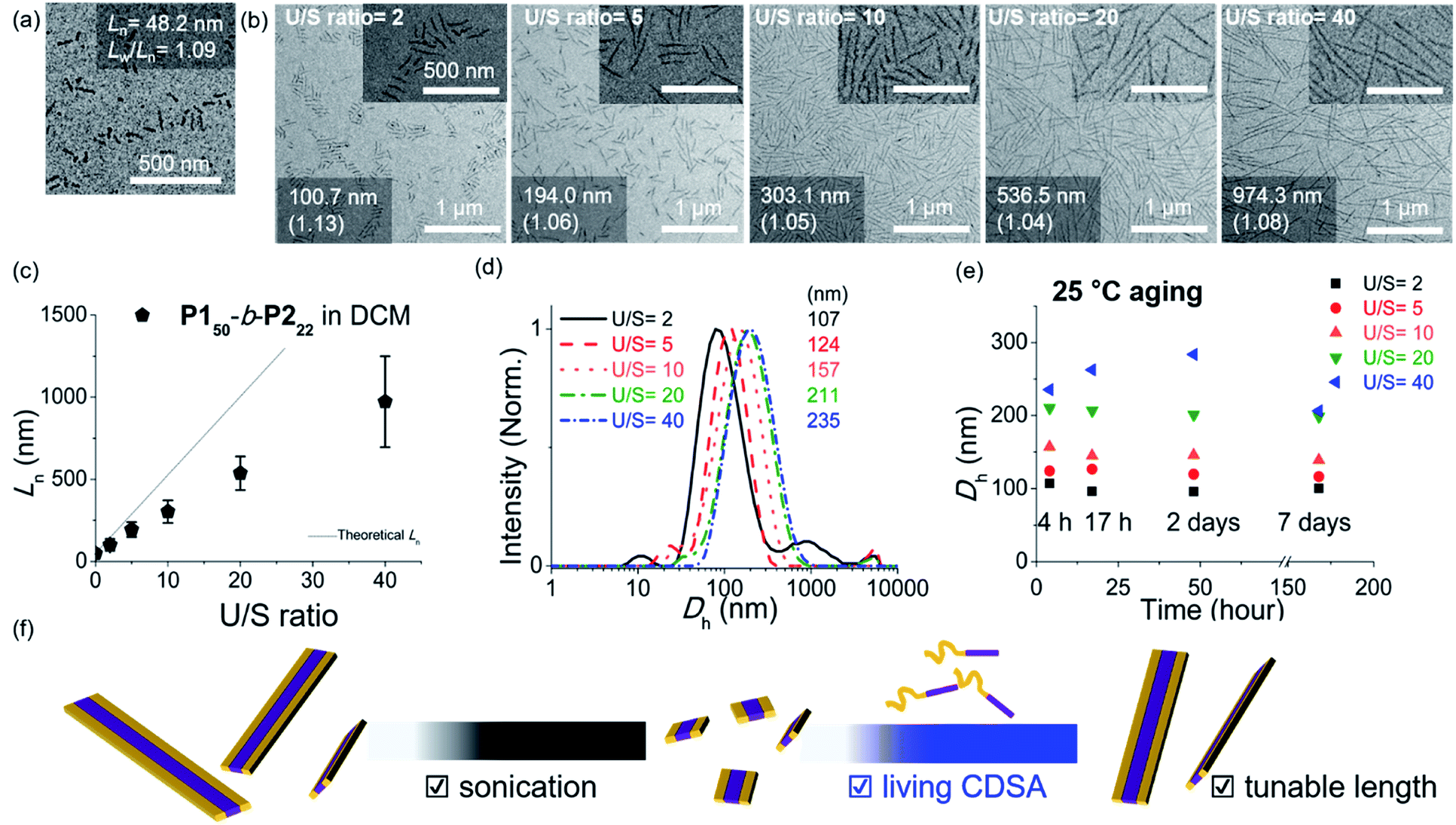 | ||
| Fig. 5 TEM images of (a) the seed-micelle of 1D nanofibers after optimized sonication and (b) length controlled 1D nanofibers showing an increase in their lengths with increasing U/S ratios (scale bar of inset images, 500 nm). The numbers in images indicated “the average Ln and its length dispersity”. (c) The plot of U/S ratios versus the Lns. (d) Dh values of the length-controlled 1D nanofibers. (e) The plot of time (h) versus the Dh values. (f) Schematic of the living CDSA of 1D nanofibers via the seeded growth mechanism. | ||
To expand the scope of the living CDSA to wider nanofibers, we attempted the living CDSA from larger BCPs. This was challenging as the larger BCPs underwent INCP during synthesis due to lower solubility, particularly in DCM. The same sonication protocol successfully produced the seed micelle (P150-b-P233: Ln = 84.6 nm, Lw/Ln = 1.13, and P150-b-P244: Ln = 66.1 nm, Lw/Ln = 1.13) by switching back to 0.1 g L−1 chloroform instead of DCM. Furthermore, we were able to obtain the corresponding unimer solutions in 0.1 g L−1 chloroform by heating at 60 °C (Fig. S31†). These unimers were then added to the seeds with various U/S ratios from 1 to 10. After 1 h of aging at RT, their Ln increased linearly up to 2.2 μm for P150-b-P233, and 4.7 μm for P150-b-P244 according to the U/S ratios while length dispersity (Lw/Ln) remained below 1.15, supporting the living CDSA by seeded growth (Fig. 6a–c, S32 and S33†). In both cases, a rise in temperature to prepare the unimer solutions might dissolve some seeds as a result of the improved solubility of the BCPs, resulting in the longer 1D nanofibers than the theoretically predicted length.54 Also, Lns in both cases remained after aging for 1 d suggesting that end-to-end coupling did not occur in chloroform (Fig. S34†).
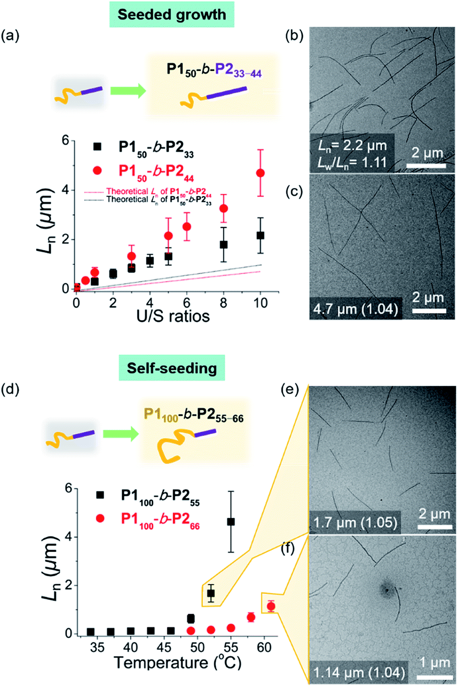 | ||
| Fig. 6 Living CDSA for larger BCPs. For P150-b-P233–44, (a) plots of U/S ratios versus Ln showing successful seeded growth, and the solid lines represented theoretical Ln values. TEM images of U/S ratios = 10 for (b) P150-b-P233, and (c) P150-b-P244. For P1100-b-P255–66, (d) plots of annealing temperature (°C) versus Ln showing CDSA through self-seeding. TEM images of the micron-sized 1D nanofibers from (e) P1100-b-P255, and (f) P1100-b-P266via self-seeding. The number in images indicates “the average Ln and its length dispersity”. | ||
To achieve seeded growth of even wider 1D nanofibers, we further heated P150-b-P255–66 up to 80 °C but failed to obtain a unimer solution due to even lower solubility (Fig. S31†). To improve solubility, we prepared new P1100-b-P255 and P1100-b-P266 with a longer shell block (with [M1]/[I] = 100). Full characterizations using 1H NMR, AF4, DLS, TEM, and AFM analyses indicated similar behaviors to the previous P150-b-P255–66, including similar average core widths of the resulting 1D nanofibers (i.e., before staining: 25.8 nm for P1100-b-P255 and 31.6 nm for P1100-b-P266 and after staining: 34.2 nm for P1100-b-P255 and 37.3 nm for P1100-b-P266 by TEM imaging) (Fig. S35 and S36†). Analogous sonication produced uniform seed solutions (P1100-b-P255: Ln = 68.7 nm, Lw/Ln = 1.18 and P1100-b-P266: Ln = 73.8 nm, Lw/Ln = 1.15). Then, instead of the seeded growth (due to their low solubility), we adopted a self-seeding strategy: thermally induced epitaxial growth.56–58 In this instance, modulating the temperature after sonication provided varying concentrations of the unimer solution in situ, thereby controlling the 1D nanofiber lengths. The seed solutions of P1100-b-P255 and P1100-b-P266 in chloroform were annealed at different temperatures ranging from 34 °C to 61 °C and cooled to room temperature (RT). After 3 h, long 1D nanofibers with uniform Ln, ranging from 68.7 nm to 4.6 μm for P1100-b-P255 and from 73.8 nm to 1.14 μm for P1100-b-P266 based on the annealing temperature, were generated with narrow dispersities (Lw/Ln: 1.04–1.21) (Fig. 6d–f, S37 and S38†). Additional aging of these wider 1D nanofibers for 1 d did not alter their lengths or widths, showing structural stability and the absence of end-to-end coupling (Fig. S39 and S40†). We were able to control the length of the 1D nanofibers up to 4.7 μm using living CDSA (either by seeded growth or self-seeding), and their core widths ranged from 12 to 32 nm, proportional to the DP of P2 (Fig. S41†).
Another advantage of the living CDSA is the capability to produce more complex block comicelles (BCMs) by further epitaxial growth from the living crystalline ends.58 To prepare BCM, another BCP2 (P325-b-P222, Mn = 17.6 kDa, Đ = 1.06) containing soluble polynorbornene derivatives (P3) was synthesized by ring-opening metathesis polymerization (Fig. S42†). This new P325-b-P222 also underwent living CDSA to form precisely controlled 1D nanofibers with Ln ranging from 165 to 1178 nm with narrow length dispersity (<1.16) via the seeded growth method (Fig. S43†). Then, a 10 g L−1 chloroform solution of the P325-b-P222 (U/S ratio = 5) was added to the seed-micelle solution of P150-b-P222 in DCM (with Ln of 169 nm and Lw/Ln = 1.10), and a ABA tri-BCM (BCM1) was obtained with uniform length and narrow dispersity (Ln = 899 nm and Lw/Ln = 1.09). The blocky structure of BCM1 was confirmed by AFM analysis, demonstrating a height difference (9 nm of P150-b-P222versus 4 nm of P325-b-P222). A clear distinction in contrast was observed by both dry and cryogenic-TEM images as the middle B block of the fully conjugated P150-b-P222 was darker due to their higher electron density. Moreover, the average core width of BCM1 was consistent throughout all the nanofibers as the length of P2 in both P150-b-P222 and P325-b-P222 was the same (Fig. 7a and S44†). Encouraged by the initial success, a more complex BCM2 was prepared through addition of the unimer solution, P150-b-P222, to another seed solution of P1100-b-P266 showing a wider 1D nanofiber (annealing temp. 52 °C, Ln = 213 nm). After 4 h of aging at 10 °C, another ABA tri-BCM2 consisting of a wider middle block was identified from AFM and TEM imaging showing a difference in the width of each block depending on the length of P2. Note that only a single strand of the thinner A block grew from both ends of the B block despite large width differences (Fig. 7b and S45†).22
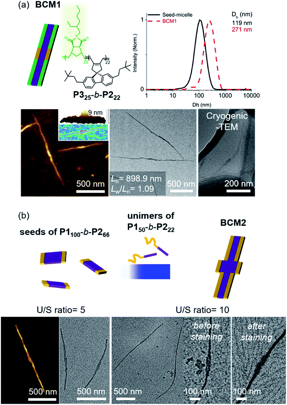 | ||
| Fig. 7 More complex BCMs were prepared by (a) adding a unimer P325-b-P222 having a different block to P150-b-P222 seed (BCM1) and (b) adding a unimer (P150-b-P222) to a wider seed (P1100-b-P266) to produce BCM2 with different widths. The number in an image (a) indicates “the average Ln and its length dispersity”. | ||
Notably, this CDSA of the fully conjugated BCP series exemplifies excellent control of the length and width and rapid growth rate. As such, the growth kinetics of P150-b-P233 was observed using real-time monitoring of the elongation of 1D nanofibers by TEM analysis. Upon the addition of unimers, 1D nanofibers elongated rapidly and reached constant lengths (Ln = 746 nm (U/S ratio = 3, Lw/Ln = 1.03) in 10 min, and Ln = 1.2 μm (U/S ratio = 5, Lw/Ln = 1.08) in just 20 min) (Fig. 8a and Table S2†). Furthermore, the kinetic data was fitted into a stretched exponential function that the Manners group previously used to describe the nanoparticle growth rates of PFS-b-(polydimethylsiloxane) (PFS-b-PDMS) (eqn (S1)†).59 In this study, this function also explained the growth kinetics of P150-b-P233 well with R2 values greater than 0.997, providing k′ values of 11 × 10−3, 9.8 × 10⁻³, 5.7 × 10⁻³, and 5.8 × 10⁻³ s−1 for U/S ratios of 2, 3, 5, and 10, respectively. Notably, these rates are about 10 times faster than those of other typical living CDSA of 1D nanowires or comparable to the highest rates (16 × 10−3)59 under a specific condition.52,59–62 By taking the average values from various U/S ratios, we obtained the parameter b of 0.54. The deviation from the theoretical value of 1 for first-order kinetics was presumably due to the influence of the flexible chain conformation of the shell, disturbing ideal crystallization during seeded growth (Fig. 8b and S46–S50†).59,63,64 Regardless, we attributed the fast kinetics of the current CDSA to the intrinsically rigid conformation of the P2 showing stretched conformation without chain folding.41,42
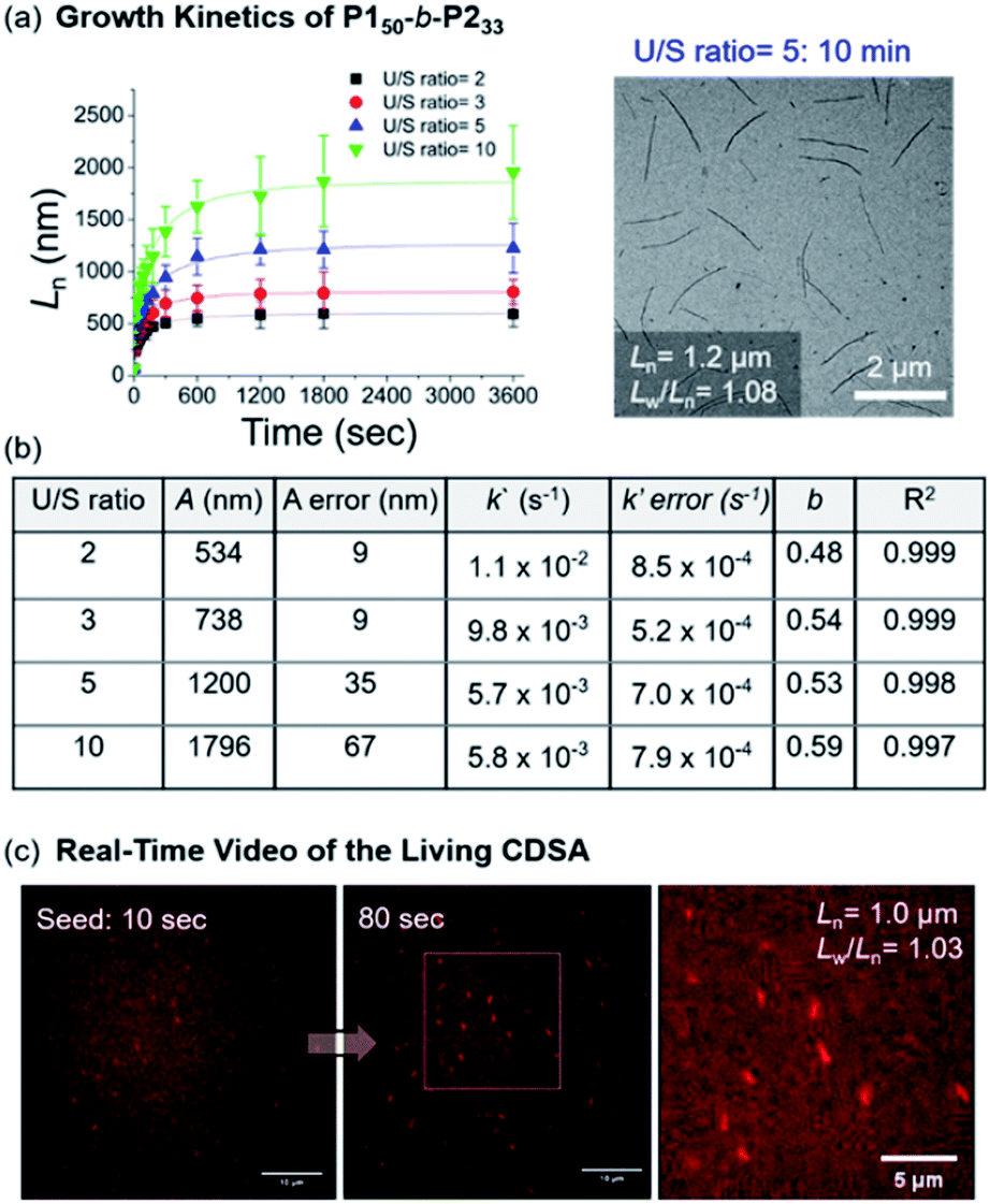 | ||
| Fig. 8 (a) Lengths (Ln) of the 1D nanofibers from P150-b-P233 over time (monitored over 13 h after adding the unimer solution to the seed micelles (Ln = 66.5 nm, Lw/Ln = 1.16)). TEM image was obtained after 10 min with U/S ratio = 5. (b) Table of kinetic data for various U/S ratios. Standard errors for the values A, k′, and b were obtained from the fitting of eqn (S1).†A is the actual length growth obtained by Ln − Lseed (seed length). k′ is the rate constant. b is the fractional power of the exponential. (c) Representative LSCM images of Video S1† at time points of 10 and 80 s (scale bars = 10 μm). We calculated the Ln of the 1D nanofibers from those images. | ||
Since the 1D nanofibers contained fluorescent P2 block and grew quickly to micron sizes, the entire CDSA could be visualized via a real-time video with a laser scanning confocal microscope (LSCM), even without additional dyes (Fig. S51 and S52†).65–67 By adding a unimer solution of P150-b-P233 to the seed in 0.01 g L−1 chloroform with U/S ratio 30, the real-time motion of nanofibers elongation up to Ln = 1.0 μm (Lw/Ln = 1.03) within 100 s was observed. This is the first video recording of the actual CDSA and this was only possible due to the fast seeded growth of conjugated P150-b-P233 which also showed stable fluorescence in solution (Fig. 8c and S52†).
Conclusions
In summary, we successfully prepared fully conjugated BCPs that underwent self-assembly into 1D nanofibers. Their lengths were controlled from 0.05 to 4.7 μm, utilizing the living CDSA technique via seeded growth or self-seeding. We were also able to tune their widths from 12 to 32 nm by modulating the DP of the core block. This excellent width control proportional to the DP of P2 was due to the fully stretched conformation of the conjugated P2 block without chain folding. As a result, the CDSA was rapid while maintaining excellent control of the dimensions of the nanofibers. Close monitoring of the growth kinetics revealed that the formation of micron-sized 1D nanofibers occurred in 20 min, much faster than the other CDSA cases. This rapid kinetics of CDSA producing fluorescent 1D nanofibers enabled real-time monitoring of their growth using confocal fluorescence microscopy. Lastly, this living CDSA technique enabled the preparation of more complex BCMs. The fast formation of fully conjugated and fluorescent nanostructures offers an efficient method for preparation of uniformly sized polymeric optoelectronic materials with controllable length and width in narrow dispersity.Conflicts of interest
There are no conflicts to declare.Acknowledgements
We are thankful for financial support from the NRF, Korea through the following grants: Creative Research Initiative Grant, and Nano-Material Technology Development Program. We thank the National Center for Inter-University Research Facilities (NCIRF) at SNU for supporting CLSM and SR-SIM.Notes and references
- X. Li, X. Wang, L. Zhang, S. Lee and H. Dai, Science, 2008, 319, 1229–1232 CrossRef CAS PubMed.
- A. C. Grimsdale, K. L. Chan, R. E. Martin, P. G. Jokisz and A. B. Holmes, Chem. Rev., 2009, 109, 897–1091 CrossRef CAS PubMed.
- F. Schwierz, Nat. Nanotechnol., 2010, 5, 487–496 CrossRef CAS PubMed.
- C. Liu, K. Wang, X. Gong and A. J. Heeger, Chem. Soc. Rev., 2016, 45, 4825–5846 RSC.
- C. Wu, C. Szymanski, Z. Cain and J. McNeill, J. Am. Chem. Soc., 2007, 129, 12904–12905 CrossRef CAS PubMed.
- J. Pecher and S. Mecking, Chem. Rev., 2010, 110, 6260–6279 CrossRef CAS PubMed.
- S. N. Patel, A. E. Javier and N. P. Balsara, ACS Nano, 2013, 7, 6056–6068 CrossRef CAS PubMed.
- J. Liu, E. Sheina, T. Kowalewski and R. D. McCullough, Angew. Chem., Int. Ed., 2002, 41, 329–332 CrossRef CAS PubMed.
- D. H. Kim, J. T. Han, Y. D. Park, Y. Jang, J. H. Cho, M. Hwang and K. Cho, Adv. Mater., 2006, 18, 719–723 CrossRef CAS.
- V. Ho, B. W. Boudouris, B. L. McCulloch, C. G. Shuttle, M. Burkhardt, M. L. Chabinyc and R. A. Segalman, J. Am. Chem. Soc., 2011, 133, 9270–9273 CrossRef CAS PubMed.
- M. A. Bader, G. Marowsky, A. Bahtiar, K. Koynov, C. Bubeck, H. Tillmann, H.-H. Hörhold and S. Pereira, J. Opt. Soc. Am. B, 2002, 19, 2250–2262 CrossRef CAS.
- D. Neher, Macromol. Rapid Commun., 2001, 22, 1365–1385 CrossRef CAS.
- R. Zhang, B. Li, M. C. Iovu, M. Jeffries-EL, G. Sauvè, J. Cooper, S. Jia, S. Tristram-Nagle, D. M. Smilgies, D. N. Lambeth, R. D. McCullough and T. Kowalewski, J. Am. Chem. Soc., 2006, 128, 3480–3481 CrossRef CAS.
- J. Liu, M. Arif, J. Zou, S. I. Khondaker and L. Zhai, Macromolecules, 2009, 42, 9390–9393 CrossRef CAS.
- Z. Yu, J. Fang, H. Yan, Y. Zhang, K. Lu and Z. Wei, J. Phys. Chem. C, 2012, 116, 23858–23863 CrossRef CAS.
- X. Li, P. J. Wolanin, L. R. MacFarlane, R. L. Harniman, J. Qian, O. E. C. Gould, T. G. Dane, J. Rudin, M. J. Cryan, T. Schmaltz, H. Frauenrath, M. A. Winnik, C. F. J. Faul and I. Manners, Nat. Commun., 2017, 8, 15909–15916 CrossRef CAS.
- X.-H. Jin, M. B. Price, J. R. Finnegan, C. E. Boott, J. M. Richter, A. Rao, S. M. Menke, R. H. Friend, G. R. Whittell and I. Manners, Science, 2018, 360, 897–900 CrossRef CAS PubMed.
- Y. Mai and A. Eisenberg, Chem. Soc. Rev., 2012, 41, 5969–5985 RSC.
- F. H. Schacher, P. A. Rupar and I. Manners, Angew. Chem., Int. Ed., 2012, 51, 7898–7921 CrossRef CAS PubMed.
- J. R. Finnegan, X. He, S. T. G. Street, J. D. Garcia-Hernandez, D. W. Hayward, R. L. Harniman, R. M. Richardson, G. R. Whittell and I. Manners, J. Am. Chem. Soc., 2018, 140, 17127–17140 CrossRef CAS PubMed.
- J. Xu, H. Zhou, Q. Yu, G. Guerin, I. Manners and M. A. Winnik, Chem. Sci., 2019, 10, 2280–2284 RSC.
- H. Qiu, Y. Gao, V. A. Du, R. Harniman, M. A. Winnik and I. Manners, J. Am. Chem. Soc., 2015, 137, 2375–2385 CrossRef CAS PubMed.
- X. He, M.-S. Hsiao, C. E. Boott, R. L. Harniman, A. Nazemi, X. Li, M. A. Winnik and I. Manners, Nat. Mater., 2017, 16, 481–488 CrossRef CAS PubMed.
- S. Ganda, M. Dulle, M. Drechsler, B. Förster, S. Förster and M. H. Stenzel, Macromolecules, 2017, 50, 8544–8553 CrossRef CAS.
- M. C. Arno, M. Inam, Z. Coe, G. Cambridge, L. J. Macdougall, R. Keogh, A. P. Dove and R. K. O'Reilly, J. Am. Chem. Soc., 2017, 139, 16980–16985 CrossRef CAS.
- Z. Li, R. Liu, B. Mai, W. Wang, Q. Wu, G. Liang, H. Gao and F. Zhu, Polymer, 2013, 54, 1663–1670 CrossRef CAS.
- J. Schmelz, A. E. Schedl, C. Steinlein, I. Manners and H. Schmalz, J. Am. Chem. Soc., 2012, 134, 14217–14225 CrossRef CAS PubMed.
- N. Petzetakis, A. P. Dove and R. K. O'Reilly, Chem. Sci., 2011, 2, 955–960 RSC.
- Y. Song, Y. Chen, L. Su, R. Li, R. A. Lettri and K. L. Wooley, Polymer, 2017, 122, 270–279 CrossRef CAS.
- S. K. Patra, R. Ahmed, G. R. Whittell, D. J. Lunn, E. L. Dunphy, M. A. Winnik and I. Manners, J. Am. Chem. Soc., 2011, 133, 8842–8845 CrossRef CAS PubMed.
- J. B. Gilroy, D. J. Lunn, S. K. Patra, G. R. Whittell, M. A. Winnik and I. Manners, Macromolecules, 2012, 45, 5806–5815 CrossRef CAS.
- D. Tao, C. Feng, Y. Cui, X. Yang, I. Manners, M. A. Winnik and X. Huang, J. Am. Chem. Soc., 2017, 139, 7136–7139 CrossRef CAS PubMed.
- L. Han, M. Wang, X. Jia, W. Chen, H. Qian and F. He, Nat. Commun., 2018, 9, 865–876 CrossRef PubMed.
- D. Tao, C. Feng, Y. Lu, Y. Cui, X. Yang, I. Manners, M. A. Winnik and X. Huang, Macromolecules, 2018, 51, 2065–2075 CrossRef CAS.
- C. E. Boott, J. Gwyther, R. L. Harniman, D. W. Hayward and I. Manners, Nat. Chem., 2017, 9, 785–792 CrossRef CAS PubMed.
- A. M. Oliver, J. Gwyther, C. E. Boott, S. Davis, S. Pearce and I. Manners, J. Am. Chem. Soc., 2018, 140, 18104–18114 CrossRef CAS.
- Y. Sha, M. A. Rahman, T. Zhu, Y. Cha, C. W. McAlister and C. Tang, Chem. Sci., 2019, 10, 9782–9787 RSC.
- K.-Y. Yoon, I.-H. Lee, K. O. Kim, J. Jang, E. Lee and T.-L. Choi, J. Am. Chem. Soc., 2012, 134, 14291–14294 CrossRef CAS PubMed.
- I.-H. Lee, P. Amaladass, K.-Y. Yoon, S. Shin, Y.-J. Kim, I. Kim, E. Lee and T.-L. Choi, J. Am. Chem. Soc., 2013, 135, 17695–17698 CrossRef CAS PubMed.
- I.-H. Lee, P. Amaladass, I. Choi, V. W. Bergmann, S. A. L. Weber and T.-L. Choi, Polym. Chem., 2016, 7, 1422–1428 RSC.
- S. Yang, S. Shin, I. Choi, J. Lee and T.-L. Choi, J. Am. Chem. Soc., 2017, 139, 3082–3088 CrossRef CAS PubMed.
- S. Yang, S.-Y. Kang and T.-L. Choi, J. Am. Chem. Soc., 2019, 141, 19138–19143 CrossRef CAS PubMed.
- E.-H. Kang, I. S. Lee and T.-L. Choi, J. Am. Chem. Soc., 2011, 133, 11904–11907 CrossRef CAS PubMed.
- G. I. Peterson, S. Yang and T.-L. Choi, Acc. Chem. Res., 2019, 52, 994–1005 CrossRef CAS PubMed.
- C. Bergerbit, F. Baffie, A. Wolpers, P.-Y. Dugas, O. Boyron, M. Taam, M. Lansalot, V. Monteil and F. D'Agosto, Angew. Chem., Int. Ed., 2020, 59, 1–7 CrossRef PubMed.
- M. Wagner, S. Holzschuh, A. Traeger, A. Fahr and U. S. Schubert, Anal. Chem., 2014, 86, 5201–5210 CrossRef CAS PubMed.
- A. C. Makan, T. Otte and H. Pasch, Macromolecules, 2012, 45, 5247–5259 CrossRef CAS.
- E.-H. Kang, S. Yang, S. Y. Yu, J. Kim and T.-L. Choi, J. Polym. Sci., Part A: Polym. Chem., 2017, 55, 3058–3066 CrossRef CAS.
- J. S. Trent, J. I. Scheinbeim and P. R. Couchman, Macromolecules, 1983, 16, 589–598 CrossRef CAS.
- S. F. Mohd Yusoff, J. B. Gilroy, G. Cambridge, M. A. Winnik and I. Manners, J. Am. Chem. Soc., 2011, 133, 11220–11230 CrossRef PubMed.
- T.-Y. Zhang and J.-T. Xu, Polym. Cryst., 2019, 2, e10047 Search PubMed.
- W.-N. He, B. Zhou, J.-T. Xu, B.-Y. Du and Z.-Q. Fan, Macromolecules, 2012, 45, 9768–9778 CrossRef CAS.
- M. E. Robinson, A. Nazemi, D. J. Lunn, D. W. Hayward, C. E. Boott, M.-S. Hsiao, R. L. Harniman, S. A. Davis, G. R. Whittell, R. M. Richardson, L. D. Cola and I. Manners, ACS Nano, 2017, 11, 9162–9175 CrossRef CAS PubMed.
- U. Tritschler, J. Gwyther, R. L. Harniman, G. R. Whittell, M. A. Winnik and I. Manners, Macromolecules, 2018, 51, 5101–5113 CrossRef CAS.
- S. Shin, F. Menk, Y. Kim, J. Lim, K. Char, R. Zentel and T.-L. Choi, J. Am. Chem. Soc., 2018, 140, 6088–6094 CrossRef CAS PubMed.
- J. Qian, G. Guerin, Y. Lu, G. Cambridge and I. Manners, Angew. Chem., Int. Ed., 2011, 50, 1622–1625 CrossRef CAS PubMed.
- J. Qian, X. Li, D. J. Lunn, J. Gwyther, Z. M. Hudson, E. Kynaston, P. A. Rupar, M. A. Winnik and I. Manners, J. Am. Chem. Soc., 2014, 136, 4121–4124 CrossRef CAS PubMed.
- Z. M. Hudson, D. J. Lunn, M. A. Winnik and I. Manners, Nat. Commun., 2014, 5, 3372–3379 CrossRef PubMed.
- C. E. Boott, E. M. Leitao, D. W. Hayward, R. F. Laine, P. Mahou, G. Guerin, M. A. Winnik, R. M. Richardson, C. F. Kaminski, G. R. Whittell and I. Manners, ACS Nano, 2018, 12, 8920–8933 CrossRef CAS PubMed.
- B. Fan, L. Liu, J.-H. Li, X.-X. Ke, J.-T. Xu, B.-Y. Du and Z.-Q. Fan, Soft Matter, 2016, 12, 67–76 RSC.
- Y. He, J.-C. Eloi, R. L. Harniman, R. M. Richardson, G. R. Whittell, R. T. Mathers, A. P. Dove, R. K. O'Reilly and I. Manners, J. Am. Chem. Soc., 2019, 141, 19088–19098 CrossRef CAS PubMed.
- J. R. Finnegan, D. J. Lunn, O. E. Gould, Z. M. Hudson, G. R. Whittell, M. A. Winnik and I. Manners, J. Am. Chem. Soc., 2014, 136, 13835–13844 CrossRef CAS PubMed.
- T. Fukui, S. Kawai, S. Fujinuma, Y. Matsushita, T. Yasuda, T. Sakurai, S. Seki, M. Takeuchi and K. Sugiyasu, Nat. Chem., 2016, 9, 493–499 CrossRef PubMed.
- S. Ogi, K. Sugiyasu, S. Manna, S. Samitsu and M. Takeuchi, Nat. Chem., 2014, 6, 188–195 CrossRef CAS PubMed.
- J. Ries, V. Udayar, A. Soragni, S. Hornemann, K. P. R. Nilsson, R. Riek, C. Hock, H. Ewers, A. A. Aguzzi and L. Rajendran, ACS Chem. Neurosci., 2013, 4, 1057–1061 CrossRef CAS PubMed.
- C. E. Boott, R. F. Laine, P. Mahou, J. R. Finnegan, E. M. Leitao, S. E. Webb, C. F. Kaminski and I. Manners, Chem.–Eur. J., 2015, 21, 18539–18542 CrossRef CAS PubMed.
- K. H. Nagamanasa, H. Wang and S. Granick, Adv. Mater., 2017, 29, 1703555–1703560 CrossRef PubMed.
Footnote |
| † Electronic supplementary information (ESI) available. See DOI: 10.1039/d0sc02891f |
| This journal is © The Royal Society of Chemistry 2020 |