
 Open Access Article
 This Open Access Article is licensed under a Creative Commons Attribution-Non Commercial 3.0 Unported Licence
Shell effects on hole-coupled electron transfer dynamics from CdSe/CdS quantum dots to methyl viologen†
Peng
Zeng
a,
Nicholas
Kirkwood
ab,
Paul
Mulvaney
ab,
Klaus
Boldt
ac and
Trevor A.
Smith
*a
aSchool of Chemistry, The University of Melbourne, Parkville, Victoria 3010, Australia. E-mail: trevoras@unimelb.edu.au; Fax: +61 3 9347 5180; Tel: +61 3 8344 6272
bBio21 Institute, The University of Melbourne, Parkville, Victoria 3010, Australia
cDepartment of Chemistry & Zukunftskolleg, University of Konstanz, 78457 Konstanz, Germany
First published on 26th April 2016
Abstract
Electron transfer (ET) dynamics from the 1Se electron state in quasi-type II CdSe/CdS core/shell quantum dots (QDs) to adsorbed methyl viologen (MV2+) were measured using femtosecond transient absorption spectroscopy. The intrinsic ET rate kET was determined from the measured average number of ET-active MV2+ per QD, which permits reliable comparisons of variant shell thickness and different hole states. The 1Se electron was extracted efficiently from the CdSe core, even for CdS shells up to 20 Å thick. The ET rate decayed exponentially from 1010 to 109 s−1 for increasing CdS shell thicknesses with an attenuation factor β ≈ 0.13 Å−1. We observed that compared to the ground state exciton 1Se1S3/2 the electron coupled to the 2S3/2 hot hole state exhibited slower ET rates for thin CdS shells. We attribute this behaviour to an Auger-assisted ET process (AAET), which depends on electron–hole coupling controlled by the CdS shell thickness.
1 Introduction
Since the initial study of semiconductor quantum dots (QDs),1–3 their optical properties have drawn significant attention, particularly in terms of their great potential for applications such as alternative solar cell materials.4–7 The core/shell heterostructure is promising for enhancing performance of solar cells6,8 and such structures have also been studied extensively for their attractive properties such as good photostability and high photoluminescence quantum yield (PL QY).9–14 Different types of core/shell QDs can be classified by the band-gap and the relative positions of the electronic energy levels of the involved semiconductor materials.11 In this paper we focus on the quasi-type II CdSe/CdS QDs, in which the excited electron is delocalized throughout the entire structure while the hole is localized in the core. The CdSe/CdS QDs are more photochemically stable than the corresponding bare core nanoparticles.10 Recently CdSe/CdS QDs were synthesized with high PL QY up to 95%,12–14 as a result of the passivation of surface defect states.15In order to optimize photon to current conversion in QD-based solar cells, one can control charge separation processes by changing the shell thickness.16,17 Previous efforts have concentrated on 1Se electron transfer (ET) from QDs to adsorbed ligands. In nanoscale systems, the Auger process can play an important role due to the strong quantum confinement and high density of hole states. Recently, Auger-assisted electron transfer (AAET) processes have been invoked to account for ultrafast electron transfer dynamics, in which the transfer of the electron was coupled to excitation of the hole.18,19 The CdS shell in core/shell nanocrystals is expected to influence electron–hole coupling, and should affect the ET dynamics. However, shell effects on hole-coupled-1Se electron transfer dynamics between semiconductor nanocrystals and adsorbed electron acceptors such as MV2+ have not been studied to date.
One difficulty in studying ET dynamics in QD-ligand complexes is the presence of multiple ET pathways when multiple acceptors adsorb to each QD.20 It is necessary to account for the distribution of acceptor molecules and to determine the mean number of active acceptors per QD, noting that not all added quencher molecules will necessarily be adsorbed to the QDs and not all adsorbates will be active in accepting electrons. Morris-Cohen et al. proposed a strategy based on transient absorption (TA) spectroscopy, which permits an accurate measurement of the average number of ET-active electron acceptors adsorbed per QD from an analysis of the initial TA bleach amplitude, and the intrinsic ET rate kET, which is the rate corresponding to only one ET-active MV2+ per QD and is independent of electron acceptor concentration.21 This approach circumvents problems associated with the inaccurate estimation of the concentrations of QDs and the uncertainty in the titration of MV2+ solutions. Furthermore, the effects of shell thickness on QD–MV2+ binding can be eliminated from the experimentally determined populations of ET-active MV2+.
Here we report a TA-based study of the effects of the CdS shell thickness on the dynamics of 1Se electron transfer in quasi-type II CdSe/CdS QDs with adsorbed electron acceptor methyl viologen (MV2+), combining aspects and approaches cited in the previous paragraph. The aim of this work was to design a system where AAET can be observed directly. In light of differences in the QD structure and composition of previous comparable studies, we have determined the intrinsic ET rate kET according to the measured average number of ET-active MV2+ per QD. A decay factor β of 0.13 Å−1 is obtained for CdS shell thicknesses up to 19 Å. We show the dependence of the 1Se population dynamics at short delay times on the CdS shell thickness in QDs, as a result of shell-modulated electron confinement. With small CdSe cores allowing a clear spectral separation between the 1S3/2 and 2S3/2 hole states (∼110 meV), we have compared the ET dynamics of the 1Se electron coupled with these two hole states and have observed a slower ET rate from the 1Se2S3/2 state than the 1Se1S3/2 state with thin CdS shell. We ascribe the slower ET rate to an AAET process, which is controlled by the capping CdS shell.
2 Experimental section
2.1 QD and QD–MV2+ sample preparation
CdSe cores of various sizes were synthesised by injecting trioctylphosphine-Se into a heated solution of cadmium phosphonate in trioctylphosphine oxide following the procedure reported by Carbone and co-workers.22CdSe/CdS core/shell QDs were synthesised as reported in a previous work.14 Cadmium oleate (0.168 M in octadecene) was used as the cadmium source and octane-thiol as the sulphur source. The required amount of each precursor for a five-monolayer CdS shell was determined using the technique described by ref. 12 and diluted with ODE to a total volume of 7.5 mL. The solutions were then loaded into separate syringes and loaded into a syringe pump.
Separately, octadecene (3 mL), oleylamine (3 mL) and 100 nmol of purified CdSe QDs (dispersed in hexane) were added to a 50 mL round-bottom flask equipped with a magnetic stirrer. The solution was held at 50 °C under vacuum (<1 mbar) for one hour, heated to 120 °C for a further 15 minutes, then placed under nitrogen and heated to 310 °C. Once the solution had reached 230 °C injection of both precursors was initiated at a rate of 3 mL per hour, corresponding to a shell growth rate of 2 monolayers per hour. Samples of 1 and 3 monolayer thickness were isolated by halting the syringe pumps after the appropriate volume of precursor had been added, cooling to 100 °C and removing one-third and one-half of the reaction solution volume, respectively. The removed fractions were mixed with 0.33 mL oleic acid and washed. The remaining reaction solution was re-heated to 310 °C with resumption of precursor injection at 230 °C. The precursor addition rate was dropped by a factor of one-third after each removal to account for the reduction in the number of QDs. After the final 5 monolayer shell thickness was achieved the remaining reaction solution was allowed to cool to room temperature and mixed with 0.33 mL oleic acid.
Each sample was washed three times via precipitation with acetone, centrifugation, and redispersion in chloroform. After the final wash the particles were redispersed in hexane and passed through a 0.2 micron PTFE filter.
By applying the above procedure, we prepared CdSe/CdS core/shell QDs with 1.2, 3.7 and 5.7 monolayers of the CdS shell. Actual shell thicknesses were measured using TEM (200 keV Technai TF-20) as shown in Fig. S1.† They were close to those predicted from shell growth calculations. The CdSe core possesses an average diameter of 4.84 ± 0.28 nm and the thickness of one monolayer (ML) of CdS shell has been determined to be 3.4 Å. The average CdS shell thicknesses of the three batches are 4.1 Å (1.2 MLs), 12.6 Å (3.7 MLs) and 19.4 Å (5.7 MLs) for each batch of CdSe/CdS QDs, respectively.
Three batches of QDs (∼1.8 nmol of each) were diluted with chloroform to a total volume of 600 μL, respectively. Thus the concentrations of all QD solutions were 3 μM. We prepared the QD–MV2+ complex solution by adding MV2+ dissolved in methanol (1 mM) into the QD solution step by step after each TA measurement. The molar ratio between added MV2+ and QDs was varied from 0 to 50. A test-tube vibrator was applied before each TA measurement to allow MV2+ to bind to the QDs homogeneously.
2.2 Femtosecond transient absorption spectroscopy
A high repetition rate titanium:sapphire regenerative amplifier system (Coherent RegA9050, centred at ∼800 nm, 1 W and 92 kHz) was employed as the laser source. The output of the RegA amplifier was re-compressed (Coherent EC9150) to ∼60 fs before being split to generate pump and probe pulses. A branch of the output was focused onto a second harmonic generation (beta barium borate (BBO)) crystal to produce 400 nm pump pulses typically of a few tens of nJ per pulse. Visible white light probe pulses were generated by focusing a small amount of the fundamental pulses (800 nm) into a 3 mm-thick sapphire substrate (Crystal Systems). A notch filter was used to block the fundamental pulse in the probe beam. Pump and probe pulses were weakly focused and overlapped at the sample with an off-axis parabolic mirror with pump spot size of 200 μm in diameter. The pump beam was mechanically chopped at, and synchronized to, a twentieth of the amplifier pulse repetition rate (4.6 kHz). The time-resolved transient absorption spectra were recorded using a high-speed fibre-optically-coupled CMOS spectrometer (Ultrafast Systems), operating at twice the modulation rate (9200 spectra per s) to sample the transmission changes of the probe beam by comparing adjacent probe pulses with and without pump pulses, synchronized to the chopper. The delay between pump and probe pulses was controlled using a motorized delay stage (Newport UTM-PP0.1, with step size of 0.66 fs and range of 800 ps). The instrument response function of the entire setup was estimated at 200 fs (FWHM) by measuring auto-correlation of fundamental pulses. A low noise level was achieved for absorption changes of below 5 × 10⁻⁵ OD, by taking advantage of the high-repetition-rate laser and high signal averaging approach coupled with an acquisition process that rejected any outlying spectra.23Samples were studied in a 2 mm-path-length cuvette, following excitation with 400 nm pump pulses, with moderated pulse energy of less than 30 nJ in order to eliminate any multiexciton effects (see ESI†). A small magnetic stirrer was used to reduce photo-degradation and thermal effects. All measurements were performed at room temperature.
3 Results and discussion
3.1 Steady-state absorption spectroscopy
The steady state absorption (normalized to the band-edge absorption peak) and photoluminescence (PL) spectra of the CdSe/CdS core/shell structure QDs studied here are shown in Fig. 1. The two lowest energy peaks in the absorption spectrum are assigned to the 1Se1S3/2 and 1Se2S3/2 states, respectively.24 The band-edge states 1Se1S3/2 are located at 591, 604 and 616 nm, and the neighbouring 1Se2S3/2 state, at 560, 570 and 585 nm for the CdSe cores with 1.2, 3.7 and 5.7 monolayer CdS shells, respectively. PL peaks exhibit a red-shift with increasing shell thickness (600 nm, 616 nm and 630 nm). The leakage of the 1Se electron wavefunction into the CdS shell accounts for the red-shift of both the 1Se1S3/2 and 1Se2S3/2 exciton states and emission peaks following the growth of the CdS shell. The PL quantum yield (QY) is improved from 24% to 54% as a result of surface passivation with thicker CdS shells.25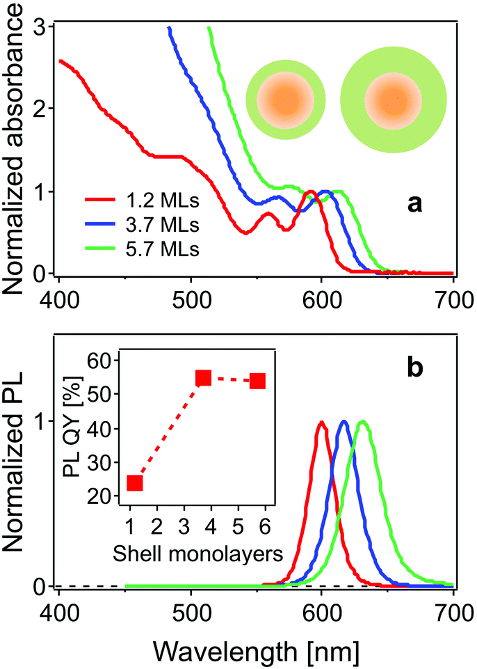 | ||
| Fig. 1 (a) Normalized absorption and (b) PL spectra of CdSe/CdS QDs with 1.2, 3.7, and 5.7 monolayers of the CdS shell in chloroform. Inset in (a): a schematic diagram showing the CdSe/CdS core/shell structure with thin (left) and thick (right) shell. Inset in (b): the PL quantum yield as a function of CdS shell thickness. | ||
The use of small core QDs, thereby increasing the wavefunction energies, allows for clear distinction of these two states separated by 110 meV, which was not the case in the work of Dworak et al.,17 but was achieved in the work of Liu et al.24 The increasing absorbance in the blue (<550 nm) with increasing CdS shelling is due to the large extinction coefficient of CdS in this spectral region.12,26
3.2 Femtosecond transient absorption spectroscopy
Fig. 2a–c show TA spectra at different delay times up to 700 ps after 400 nm excitation of different core/shell QDs in the absence and presence of MV2+. All samples were excited with the average number of excitons per particle far less than 1 (see ESI†). Electrons and holes are promoted to hot energy levels, and relax to the band-edge level, giving rise to the 1Se bleaching peaks.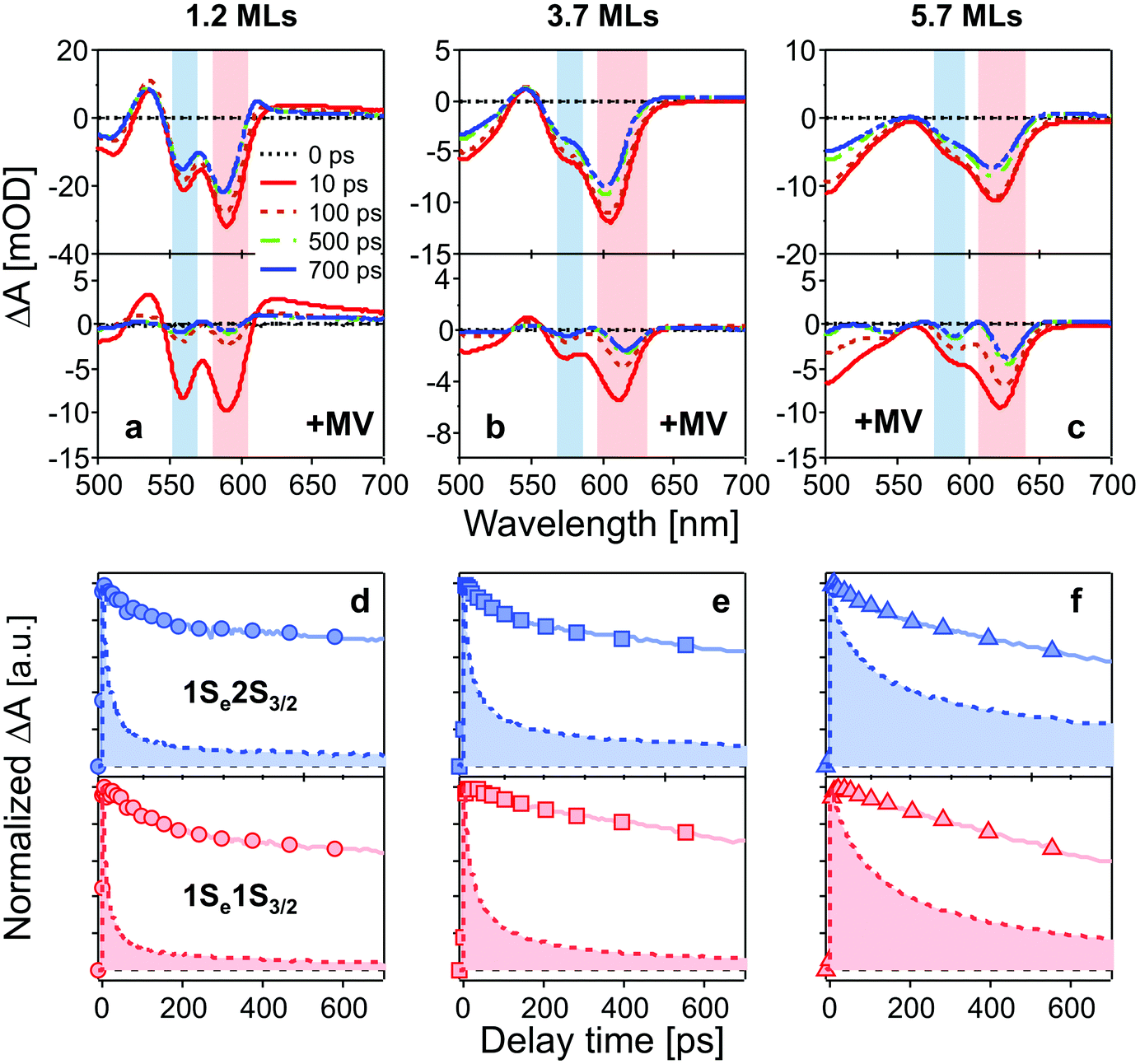 | ||
| Fig. 2 (a–c): TA spectra of CdSe/CdS QDs (top) and QD–MV2+ complexes (bottom) at different delay times after 400 nm excitation. Bleaching peaks are assigned to different exciton states indicated by color blocks in each panel (red: 1Se1S3/2; blue: 1Se2S3/2). (d–f): normalized bleaching kinetics of 1Se1S3/2 (bottom, red) and 1Se2S3/2 (top, blue) state in three batches of QDs (solid lines) and QD–MV2+ complexes (dashed lines and filled areas) within 700 ps. The concentrations of all QD solutions were 3 μM and the number of added MV2+ per QD was 10 for all QD–MV2+ samples. The excitation power was kept low for all measurements in order to avoid multi-exciton effect (see ESI†). | ||
In Fig. 2a–c, bleaching peaks assigned to the 1Se1S3/2 and 1Se2S3/2 states are clearly distinguished27–29 and all three samples have an energy difference greater than ∼110 meV between the two states. A contribution of the 2S3/2 holes to the 1Se2S3/2 bleaching kinetics may complicate the interpretation. The energy of hot holes dissipates quickly, within tens of picoseconds, due to the high hole state density.24,30,31 At long delay times, the bleaching of the 1Se2S3/2 state is consequently dominated by the state-filling effect of 1Se electrons, which is expected to resemble the bleaching at 1Se1S3/2.20,32Fig. 3 compares the measured bleaching kinetics from the 1Se1S3/2 and 1Se2S3/2 states in CdSe/1.2CdS QDs (see ESI† for CdSe/3.7CdS and CdSe/5.7CdS). The 1Se1S3/2 and 1Se2S3/2 states exhibit identical decay kinetics as expected at long times. Hot hole relaxation from 2S3/2 to 1S3/2 is revealed by a faster decay behaviour in the 2S3/2 state within the initial 100 ps. Fig. 3(b) shows the 2S3/2 hole transition dynamics extracted from normalized 2S3/2 and 1S3/2 bleach dynamics. A single exponential fitting gives a decay time constant of 30 ps. Here we ascribe the observed 2S3/2–1S3/2 hole relaxation to a channel coupled to emission of LO phonons, which involves slow relaxation from 1 ps to tens of ps.24,33
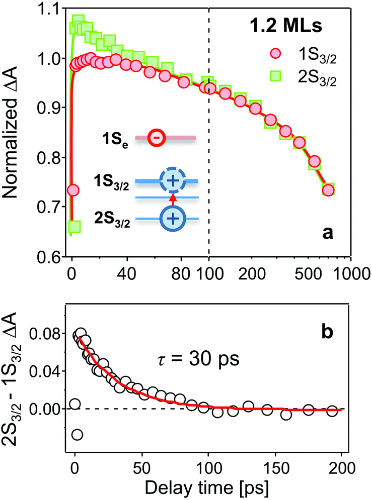 | ||
| Fig. 3 (a) Comparison of bleaching kinetics of 1Se1S3/2 (red circles) and 1Se2S3/2 (green squares) states in CdSe/1.2CdS QDs after excitation at 400 nm. The two TA kinetics are normalized at long time scales. (b) The 2S3/2 hole transition extracted from normalized 2S3/2 and 1S3/2 bleach dynamics. A single exponential fitting gives a decay time constant of 30 ps. Inset in (a): the 2S3/2 hot hole relaxes to the 1S3/2 state. Note that the time scale between 100 and 1000 ps is logarithmic. | ||
The time-resolved bleaching kinetics (Fig. 2d–f) were extracted from the TA spectra of Fig. 2a–c. Multiexponential functions were applied to fit the decay kinetics in the QDs and the results are summarized in Table 1. For QDs in the absence of MV2+, the time traces all exhibit a dominant slow-decaying component (the exact time constants of the slow components from the fitting are not shown because they are far beyond our delay time window), which is attributed to the relaxation of electrons to the ground state, predominantly through radiative pathways.34 The fast component of the 1Se1S3/2 state is suppressed by growth of the CdS shell. We ascribe this fast relaxation process to electrons being trapped at surface defects.32,35 Capping with 5.7 MLs of CdS shell eliminates the fast relaxation component as the surfaces of the CdSe cores are well passivated by the thick shell.
| Monolayer | Energy level | τ 1 (A1) | τ 2 (A2) |
|---|---|---|---|
| 1.2 MLs | 1Se1S3/2 | 76 ps (0.1) | >1 ns (0.9) |
| 1Se2S3/2 | 52 ps (0.1) | >1 ns (0.9) | |
| 3.7 MLs | 1Se1S3/2 | 99 ps (0.1) | >1 ns (0.9) |
| 1Se2S3/2 | 77 ps (0.2) | >1 ns (0.8) | |
| 5.7 MLs | 1Se1S3/2 | — | >1 ns (1) |
| 1Se2S3/2 | 108 ps (0.1) | >1 ns (0.9) | |
The population dynamics of the 1Se electron were also investigated at short delay times. Fig. 4 shows the build-up kinetics of the 1Se1S3/2 bleach signal, which is attributed to the re-population of the 1Se states after excitation. The change in population is fast and shows a decreasing rate of change (from 300 to 700 fs) with increasing CdS shell thickness. This is in contrast to what might be expected for a phonon-assisted transition, which occurs slowly between the energy levels separated by a large energy gap in QDs with thin CdS shells. Klimov et al. attributed these abnormal trends to an ultrafast Auger-assisted 1Pe-to-1Se transition,36 which involves a confinement-enhanced electron relaxation process bypassing the phonon-bottleneck effect. The observed dependence of the build-up kinetics on the shell thickness can be interpreted in terms of the weak confinement of electrons in the presence of the thick CdS shell.
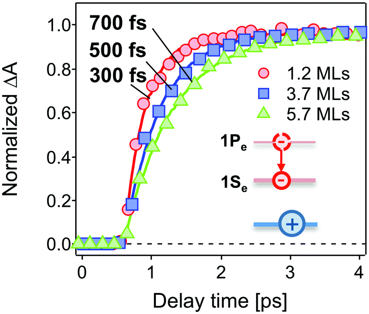 | ||
| Fig. 4 Normalized initial build-up kinetics of 1Se1S3/2 in the CdSe core capped with 1.2 MLs (red circles), 3.7 MLs (blue squares) and 5.7 MLs (green triangles) of the CdS shell. The build-up time constants are derived by a single exponential fitting (solid lines), showing an increase with increasing shell thickness. The excitation wavelength was 400 nm. Inset: the 1Pe hot electron relaxes to the 1Se state. | ||
The TA spectra (see Fig. 2a–c), in the presence of MV2+, present the same features but different time-dependent trends to those observed in the absence of MV2+. In the presence of MV2+, clear red-shifts of the bleach peaks are observed in each sample during the measurement time window of 700 ps. This may be due to a Stark-shift of the exciton bands in the charge separated states.37,38
MV+ has a broad absorption band above 600 nm that can potentially complicate interpretation of TA spectra. Electron transfer from QDs to MV2+ leads to the formation of MV+ cations, which will contribute to the TA signals in a range overlapping the 1Se bleach of QDs. Fig. S3† shows TA signals in QDs and QD–MV2+ complexes in a wavelength range between 600 and 700 nm. The contribution of MV+ to TA signals is negligible due to the small <Nex> we excited, indicating a good approximation of our analysis on TA signals of QDs. We could also give an estimation of TA signals arising from MV+. The maximum extinction coefficient of MV+ is 13![[thin space (1/6-em)]](https://www.rsc.org/images/entities/char_2009.gif) 900 M−1 cm−1 at λmax = 606 nm.39 Given that QD = 3 μM, <Nex> = 0.1, and pathlength = 2 mm, the greatest change of TA signals with an addition of MV+ is less than 0.8 mOD, which is far less than that at the 1Se bleach peaks we investigated (>10 mOD).
900 M−1 cm−1 at λmax = 606 nm.39 Given that QD = 3 μM, <Nex> = 0.1, and pathlength = 2 mm, the greatest change of TA signals with an addition of MV+ is less than 0.8 mOD, which is far less than that at the 1Se bleach peaks we investigated (>10 mOD).
The QD–MV2+ complexes show a markedly faster decay than the QDs, due to the ET channel from the QDs to the adsorbed MV2+ radicals (see Fig. 2d–f). Furthermore, the TA kinetics of 1Se in all three batches of QD–MV2+ complexes exhibit faster decays with increasing concentrations of MV2+ (see ESI†). This concentration dependence is ascribed to the multiple ET pathways when multiple ET-active MV2+ moieties are associated with each QD. Following the work of Morris-Cohen et al.,21 we calculated the intrinsic ET rate kET, which is the rate of electron transfer for only one ET-active MV2+ radical per QD. The observed ET rate kET,obs is assumed to equal nkET,40 where n is the number of ET-active MV2+ binding to one QD. With an assumption of a Poisson distribution of QD–MV2+ binding,41–43 the probability f(n), of QDs with n absorbed MV2+ radicals is given by:
 | (1) |
| λ = −ln(B/B0) | (2) |
Fig. 5 shows λ as a function of concentration of added free MV2+ in the QD–MV2+ complex solutions. Fitting the data using a Langmuir isotherm model:
 | (3) |
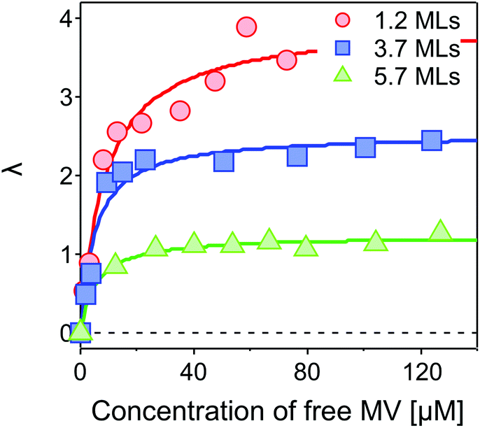 | ||
| Fig. 5 Average number of ET-active MV2+ per QD, λ, as a function of concentration of free MV2+ in the complex solution. A Langmuir isotherm model is applied to fit the results for the CdSe core capped with 1.2 MLs (red circles), 3.7 MLs (blue squares) and 5.7 MLs (green triangles) of the CdS shell, respectively. The fits yield maximum average numbers of λmax = 3.94 ± 0.22, 2.53 ± 0.11, and 1.23 ± 0.04 for 1.2, 3.7 and 5.7 MLs of the CdS shell, respectively. | ||
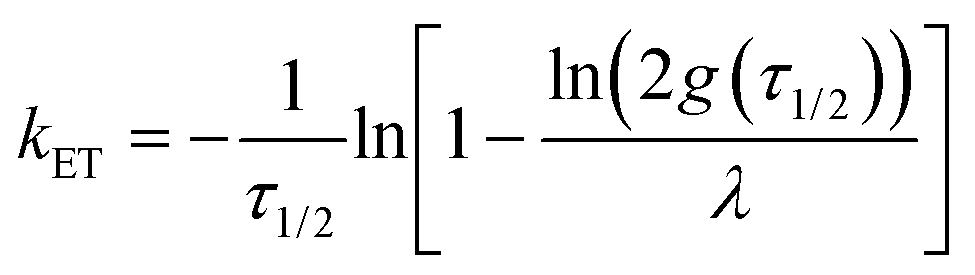
Applying an infinite sum of exponentials to fit the measured TA bleaching decay, and combining eqn (1) of the Poisson distribution, the intrinsic ET rate kET is derived as (see ESI†):
 | (4) |
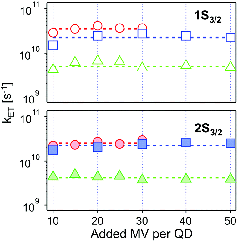 | ||
| Fig. 6 Intrinsic ET rates from 1Se1S3/2 (top, open symbols) and 1Se2S3/2 (bottom, solid symbols) state in CdSe/1.2CdS (red circles), CdSe/3.7CdS (blue squares) and CdSe/5.7CdS (green triangles) derived from eqn (4), as a function of added MV2+. Dashed lines refer to the averaged ET rates. The experimental conditions were kept identical at each molar ratio for each batch of QD–MV2+ complex. | ||
| Monolayer | Thickness/Å | k ET1/1010 s−1 | k ET2/1010 s−1 |
|---|---|---|---|
| 1.2 ML | 4.1 | 3.52 ± 0.41 | 2.52 ± 0.28 |
| 3.7 ML | 12.6 | 2.25 ± 0.45 | 2.24 ± 0.34 |
| 5.7 ML | 19.4 | 0.49 ± 0.09 | 0.41 ± 0.06 |
The values obtained lie in the range 108–1010 s−1 in good agreement with recent published results for other QD–acceptor pairs.17,18,21,45Fig. 7 shows an exponential fit kET = k0e−βt, to the measured intrinsic ET rate kET1 from 1Se1S3/2 with varying shell thickness t, yielding an attenuation factor β of 0.13 ± 0.05 Å−1. The error indicates the 95% confidence interval of the fitting parameters given by the fitting method.
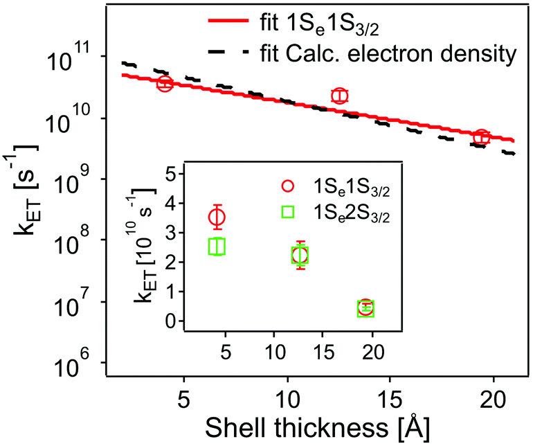 | ||
| Fig. 7 Dependence of intrinsic ET rates kET1 from 1Se1S3/2 (red circles) and kET2 from 1Se2S3/2 (inset, green squares) in QD–MV2+ complexes on CdS shell thickness. Error bars indicate the calculated standard deviations in averaging the ET rates. Also shown is the calculated electron density (black dashed line) with different shell thickness (see text and ESI†). For comparison, the electron density is scaled to the measured ET rate. | ||
The value of β we obtained in the CdSe/CdS–MV2+ complexes studied here is significantly lower than results published recently by Dworak et al.17 for a related system. They reported a value of β = 0.33 Å−1 for CdSe/CdS–MV2+ complexes with larger CdSe cores (6.1 nm in diameter) capped with thinner 1.75–5.25 Å-thick CdS shells. Hines et al. obtained a smaller value of β = 0.08 Å−1 in CdSe/TiO2 bridged by organic molecules with an increasing length from 3 to 21 Å.45 Importantly, we have determined the actual number of ET-active MV2+ acceptor molecules on the QDs and used this number in the calculation of the intrinsic ET rates, instead of using the number of added MV2+ that was assumed in Dworak's work. As discussed above (see Fig. 5), the actual number of ET-active MV2+ molecules per QD drops as the thickness of the shell increases in the QD–MV2+ complexes (for identical added acceptor molecule concentrations), thereby leading to an observed faster ET rate.
According to the Marcus–Hush model for ET46,47
 | (5) |
In order to estimate the effect of mechanism (ii), we consider the electron wavefunction overlap |H(R)|2 and assume that it is proportional to the electron density |Ψ(R)|2 at the QD–acceptor interface, i.e. the electron transfer rate kET ∝ |Ψ(R)|2. We extract relative values of |Ψ(R)|2 at the surface of the QDs from the simulation results, as shown in Fig. S5 and S6.† An exponential fitting to the scaled |Ψ(R)|2 with the CdS shell thickness yields a decay factor β of 0.18 Å−1, which is in good agreement with the measured decay constant.
In using the widely-applied ET model discussed above, it is generally assumed that the 1Se ET dynamics are independent of the hole energy, however, as indicated in Fig. 7 inset, a noticeably slower ET rate kET2 = 2.52 × 10¹⁰ s−1 compared to kET1 = 3.52 × 10¹⁰ s−1 is found in the case of the CdSe core capped with 1.2 MLs of the CdS shell, whereas for the 3.7 and 5.7 ML the rates are essentially identical in each case (see Table 2). This observation is in contrast to what one may expect: the two 1Se ET rates should be identical regardless of the hole state, indeed the rates from the two states in CdSe/3.7CdS and CdSe/5.7CdS are very similar. Lian and co-workers have recently proposed the existence of an additional, Auger-assisted electron transfer (AAET) channel,18 in which the ET is coupled to excitation of the hole. Here we first interpret the slower rate kET2 by considering a lack of Auger-assisted 1S3/2 to 2S3/2 or higher hole transitions coupled to the electron transfer at short time scales. As shown in Fig. 8, for the 1Se1S3/2 state, the electron transfer to the MV2+ is accompanied by the hole becoming excited to higher levels via the Auger process. At short time scales before the 2S3/2 hole relaxes to the lowest state, the Auger process cannot occur, resulting in slower transfer rates. According to Zhu, the AAET is given by:18
 | (6) |
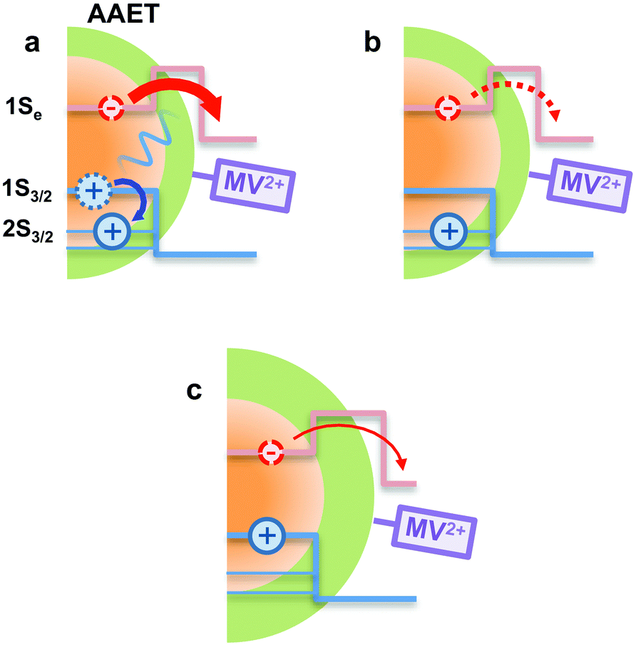 | ||
| Fig. 8 Schematic illustration of the AAET process. (a): In the AAET process, electron transfer to MV2+ is accompanied by the excitation of the 1S3/2 hole to higher levels. (b): The Auger process lacks the 1S3/2 to 2S3/2 hole transition, leading to inefficient AAET. (c): With thick shell, the Auger-assisted channel is cut off due to the weak electron–hole coupling. | ||
CdS shells could affect the AAET channel by controlling electron–hole coupling in CdSe/CdS QDs. With thick CdS shells, the electron wavefunction is spread over the core/shell heterostructure while the hole wavefunction is almost confined within the core. Thus the importance of the Auger-assisted channel is reduced, due to the decreasing overlap of the electron and hole wavefunctions (see Fig. S4†). As mentioned above, the population dynamics of the 1Se state (see Fig. 4) also reflect the extent of the Auger type process induced by carrier confinement, which could be controlled by the CdS shell.
4. Conclusions
In summary, we have studied the effects of the CdS shell thickness on the dynamics of 1Se electron transfer from quasi-type II CdSe/CdS QDs to adsorbed methyl viologen cations. We have measured the number of ET-active MV2+ per QD with a TA-based method and determined the intrinsic ET rate. The electrons are extracted by the adsorbed MV2+ radicals and the ET rate decreases with increasing shell thicknesses, with an attenuator factor β of 0.13 Å−1. There is a difference in ET rates for the 1Se1S3/2 and 1Se2S3/2 states, which we attribute to an AAET process, in which the 1Se electron transfer to the viologen is accompanied by the excitation of the hole to higher levels. We have also found that the lowest 1Se state populates more slowly with increasing CdS shell as a result of weakened electron confinement. These results suggest that electron transfer and Auger relaxation processes can be tailored in these systems by optimising the shell thickness.Acknowledgements
TAS and KB acknowledge the support of the Universities Australia-German Academic Exchange Service (UA-DAAD) Australia-Germany Joint Research Cooperation Scheme award. PZ acknowledges the provision of an IPRS/APA (Int) scholarship. KB also gratefully acknowledges financial support from the Fonds der Chemischen Industrie through a Liebig Fellowship and from the University of Konstanz Zukunftskolleg.References
- A. Henglein and M. Gutierrez, Ber. Bunsen-Ges. Phys. Chem., 1983, 87, 852–858 CrossRef CAS.
- L. E. Brus, J. Chem. Phys., 1984, 80, 4403 CrossRef CAS.
- L. Brus, J. Phys. Chem., 1986, 90, 2555–2560 CrossRef CAS.
- I. Gur, N. A. Fromer, M. L. Geier and A. P. Alivisatos, Science, 2005, 310, 462–465 CrossRef CAS PubMed.
- A. J. Nozik, Nano Lett., 2010, 10, 2735–2741 CrossRef CAS PubMed.
- H. Zhu and T. Lian, Energy Environ. Sci., 2012, 5, 9406 CAS.
- P. V. Kamat, J. Phys. Chem. Lett., 2013, 4, 908–918 CrossRef CAS PubMed.
- C. M. Cirloganu, L. A. Padilha, Q. Lin, N. S. Makarov, K. A. Velizhanin, H. Luo, I. Robel, J. M. Pietryga and V. I. Klimov, Nat. Commun., 2014, 5, 4148 CAS.
- B. O. Dabbousi, J. RodriguezViejo, F. V. Mikulec, J. R. Heine, H. Mattoussi, R. Ober, K. F. Jensen and M. G. Bawendi, J. Phys. Chem. B, 1997, 101, 9463–9475 CrossRef CAS.
- J. J. Li, Y. A. Wang, W. Guo, J. C. Keay, T. D. Mishima, M. B. Johnson and X. Peng, J. Am. Chem. Soc., 2003, 125, 12567–12575 CrossRef CAS PubMed.
- P. Reiss, M. Protière and L. Li, Small, 2009, 5, 154–168 CrossRef CAS PubMed.
- J. van Embden, J. Jasieniak and P. Mulvaney, J. Am. Chem. Soc., 2009, 131, 14299–14309 CrossRef CAS PubMed.
- O. Chen, J. Zhao, V. P. Chauhan, J. Cui, C. Wong, D. K. Harris, H. Wei, H.-S. Han, D. Fukumura, R. K. Jain and M. G. Bawendi, Nat. Mater., 2013, 12, 445–451 CrossRef CAS PubMed.
- K. Boldt, N. Kirkwood, G. A. Beane and P. Mulvaney, Chem. Mater., 2013, 25, 4731–4738 CrossRef CAS.
- C. Yi and K. L. Knappenberger, Nanoscale, 2015, 7, 5884–5891 RSC.
- H. Zhu, N. Song and T. Lian, J. Am. Chem. Soc., 2010, 132, 15038–15045 CrossRef CAS PubMed.
- L. Dworak, V. V. Matylitsky, V. V. Breus, M. Braun, T. Basché and J. Wachtveitl, J. Phys. Chem. C, 2011, 115, 3949–3955 CAS.
- H. Zhu, Y. Yang, K. Hyeon-Deuk, M. Califano, N. Song, Y. Wang, W. Zhang, O. V. Prezhdo and T. Lian, Nano Lett., 2014, 14, 1263–1269 CrossRef CAS PubMed.
- K. Hyeon-Deuk, J. Kim and O. V. Prezhdo, J. Phys. Chem. Lett., 2015, 6, 244–249 CrossRef CAS PubMed.
- J. Huang, D. Stockwell, Z. Huang, D. L. Mohler and T. Lian, J. Am. Chem. Soc., 2008, 130, 5632–5633 CrossRef CAS PubMed.
- A. J. Morris-Cohen, M. T. Frederick, L. C. Cass and E. A. Weiss, J. Am. Chem. Soc., 2011, 133, 10146–10154 CrossRef CAS PubMed.
- L. Carbone, C. Nobile, M. de Giorgi, F. D. Sala, G. Morello, P. Pompa, M. Hytch, E. Snoeck, A. Fiore, I. R. Franchini, M. Nadasan, A. F. Silvestre, L. Chiodo, S. Kudera, R. Cingolani, R. Krahne and L. Manna, Nano Lett., 2007, 7, 2942–2950 CrossRef CAS PubMed.
- B. E. Robotham, Ph.D. thesis, Unversity of Melbourne, 2013 Search PubMed.
- C. Liu, J. J. Peterson and T. D. Krauss, J. Phys. Chem. Lett., 2014, 5, 3032–3036 CrossRef CAS PubMed.
- W. Nan, Y. Niu, H. Qin, F. Cui, Y. Yang, R. Lai, W. Lin and X. Peng, J. Am. Chem. Soc., 2012, 134, 19685–19693 CrossRef CAS PubMed.
- L. Wang, Y. Tian, T. Okuhata and N. Tamai, J. Phys. Chem. C, 2015, 119, 17971–17978 CAS.
- D. Norris and M. Bawendi, Phys. Rev. B: Condens. Matter, 1996, 53, 16338–16346 CrossRef CAS.
- A. Pandey and P. Guyot-Sionnest, J. Chem. Phys., 2007, 127, 104710 CrossRef PubMed.
- J. R. Caram, H. Zheng, P. D. Dahlberg, B. S. Rolczynski, G. B. Griffin, D. S. Dolzhnikov, D. V. Talapin and G. S. Engel, J. Chem. Phys., 2014, 140, 084701 CrossRef PubMed.
- P. Kambhampati, Acc. Chem. Res., 2011, 44, 1–13 CrossRef CAS PubMed.
- S. L. Sewall, R. R. Cooney, K. E. H. Anderson, E. A. Dias and P. Kambhampati, Physical Review B, 2006, 74, 235328 Search PubMed.
- V. I. Klimov, D. W. McBranch, C. A. Leatherdale and M. G. Bawendi, Phys. Rev. B: Condens. Matter, 1999, 60, 13740–13749 CrossRef CAS.
- R. R. Cooney, S. L. Sewall, K. E. H. Anderson, E. A. Dias and P. Kambhampati, Phys. Rev. Lett., 2007, 98, 177403 CrossRef.
- M. D. Peterson, L. C. Cass, R. D. Harris, K. Edme, K. Sung and E. A. Weiss, Annu. Rev. Phys. Chem., 2014, 65, 317–339 CrossRef CAS PubMed.
- V. I. Klimov, C. J. Schwarz, D. W. McBranch and C. A. Leatherdale, Phys. Rev. B: Condens. Matter, 1999, 60, 2177 CrossRef.
- V. I. Klimov and D. W. McBranch, Phys. Rev. Lett., 1998, 80, 4028–4031 CrossRef CAS.
- H. Zhu, N. Song, W. Rodríguez-Córdoba and T. Lian, J. Am. Chem. Soc., 2012, 134, 4250–4257 CrossRef CAS PubMed.
- K. Wu, N. Song, Z. Liu, H. Zhu, W. Rodríguez-Córdoba and T. Lian, J. Phys. Chem. A, 2013, 117, 7561–7570 CrossRef CAS PubMed.
- T. Watanabe and K. Honda, J. Phys. Chem., 1982, 86, 2617–2619 CrossRef CAS.
- N. Song, H. Zhu, S. Jin, W. Zhan and T. Lian, ACS Nano, 2011, 5, 613–621 CrossRef CAS PubMed.
- N. Song, H. Zhu, S. Jin and T. Lian, ACS Nano, 2011, 5, 8750–8759 CrossRef CAS PubMed.
- M. Tachiya, Chem. Phys. Lett., 1975, 33, 289–292 CrossRef CAS.
- S. Sadhu, M. Tachiya and A. Patra, J. Phys. Chem. C, 2009, 113, 19488–19492 CAS.
- A. J. Morris-Cohen, V. Vasilenko, V. A. Amin, M. G. Reuter and E. A. Weiss, ACS Nano, 2012, 6, 557–565 CrossRef CAS PubMed.
- D. A. Hines, R. P. Forrest, S. A. Corcelli and P. V. Kamat, J. Phys. Chem. B, 2015, 119, 7439–7446 CrossRef CAS PubMed.
- R. A. Marcus and N. Sutin, Biochim. Biophys. Acta, 1985, 811, 265–322 CrossRef CAS.
- A. L. Kaledin, T. Lian, C. L. Hill and D. G. Musaev, J. Phys. Chem. B, 2015, 119, 7651–7658 CrossRef CAS PubMed.
- J. S. de Sousa, J. A. K. Freire and G. A. Farias, Phys. Rev. B: Condens. Matter, 2007, 76, 155317 CrossRef.
Footnote |
| † Electronic supplementary information (ESI) available. See DOI: 10.1039/c6nr00168h |
| This journal is © The Royal Society of Chemistry 2016 |