
 Open Access Article
 This Open Access Article is licensed under a Creative Commons Attribution-Non Commercial 3.0 Unported Licence
Vibrationally induced color shift tuning of photoluminescence in Ce3+-doped garnet phosphors†
Yuan-Chih
Lin
 a,
Paul
Erhart
b and
Maths
Karlsson
*a
a,
Paul
Erhart
b and
Maths
Karlsson
*a
aDepartment of Chemistry and Chemical Engineering, Chalmers University of Technology, SE-412 96 Göteborg, Sweden. E-mail: maths.karlsson@chalmers.se
bDepartment of Physics, Chalmers University of Technology, SE-412 96 Göteborg, Sweden
First published on 29th May 2019
Abstract
A critical challenge in the field of phosphor converted white light emitting diodes (pc-WLEDs) pertains to understanding and controlling the variation of emission color with device temperature. Here we, through a combined photoluminescence (PL) and Raman spectroscopy study of the three garnet type phosphors Ce3+-doped Y3Al5O12 (YAG:Ce3+), Ca3Sc2Si3O12 (CSS:Ce3+), and Sr3Y2Ge3O12 (SYG:Ce3+), show that the color of the PL is systematically shifted upon changing the operation temperature of the phosphor. A general trend is observed that the PL exhibits a red-shift as a function of increasing temperature, until the point at which the vibrational modes of the CeO8 moieties, which induce dynamical tetragonal distortions of the CeO8 dodecahedra, are fully activated. Upon further temperature increase, the PL turns to a blue-shift because of a counteracting and predominating effect of thermal lattice expansion that progressively makes the CeO8 dodecahedra more cubal like. Since this behavior is the result of the symmetry relations intrinsic to the garnet structure, the present mechanism can be generally applicable to materials of this type. It thereby provides a route for tuning the PL of this important class of phosphor materials.
1 Introduction
The economic and environmental benefits of phosphor converted white light emitting diodes (pc-WLEDs) have been increasingly appreciated in recent years.1–4 The most widely used type of pc-WLEDs is composed of an (In,Ga,)N based blue LED that is used to excite either a yellow phosphor or a mixture of green and red phosphors, resulting in the emission of white light.5,6 Phosphors based on Ce3+-doped garnet type host lattices have garnered particular attention and are commonly used as green-to-yellow component(s) in pc-WLEDs because of their high quantum efficiency and chemical stability.3,7,8 The garnet crystal structure, of general formula A3B2C3O12, can be described by a 160-atom body-centered cubic unit cell of the O10h (Ia![[3 with combining macron]](https://www.rsc.org/images/entities/char_0033_0304.gif) d) space group.9 The structure may be also viewed as a network of AO8 dodecahedra, BO6 octahedra, and CO4 tetrahedra, which are connected to each other via O atoms that are shared between neighboring cation-oxygen polyhedra, see Fig. 1. The dodecahedral coordination of A may be described as a slightly tetragonally distorted cubal environment, the tetragonality of which typically increases when A ions are substituted by Ce3+.7,10,11
d) space group.9 The structure may be also viewed as a network of AO8 dodecahedra, BO6 octahedra, and CO4 tetrahedra, which are connected to each other via O atoms that are shared between neighboring cation-oxygen polyhedra, see Fig. 1. The dodecahedral coordination of A may be described as a slightly tetragonally distorted cubal environment, the tetragonality of which typically increases when A ions are substituted by Ce3+.7,10,11
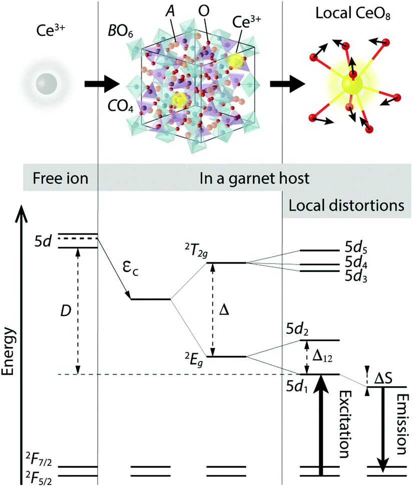 | ||
| Fig. 1 Schematic illustration of the atomic environments (top) and energy level diagrams (bottom) of a free Ce3+ ion, a Ce3+-doped garnet phosphor (a unit cell), and the local coordination of Ce3+ in a garnet host. | ||
Two major effects dictate the PL properties; the centroid shift and the crystal field splitting. The centroid shift refers to a lowering in the average energy of the 5d levels of the Ce3+ ions due to a decrease in the interelectronic repulsion, cf. εc in Fig. 1.12,13 This effect depends on the polarizability of the surrounding anion (oxygen) ligands and on the covalency of the chemical bonds between the ligands and the activator ion.12,14,15 The crystal field splitting refers to the splitting of the 5d levels of the Ce3+ ion into an upper, triply degenerate, 2T2g state and a lower, doubly degenerate, 2Eg state, which are separated by an energy Δ in a cubal environment, see Fig. 1.7,12,13,16,17 The 2T2g and 2Eg states, which are degenerate for perfect cubal symmetry, are further split into five non-degenerate levels due to the tetragonal crystal field acting on the Ce3+ ion that originates from tetragonal distortions of the cubal environment of the CeO8 moiety.7,13 The strength of the tetragonal crystal field may be measured by the energy separation between the two lowest 5d levels (5d1 and 5d2), cf. Δ12 in Fig. 1.13,18 The unusually large crystal field splitting for many Ce3+-doped garnet phosphors enables excitation in the blue wavelength region. After vibrational relaxation in the 5d1 level, one obtains emission in the green-yellow wavelength range, which is again followed by vibrational relaxation in the 4f electronic ground state. The process of the energy loss through the vibrational relaxation gives rise to the so-called Stokes shift, cf. ΔS in Fig. 1.
Generally, the effect of incorporating Ce3+ ions into a host crystal is quantified by the energy difference between the lowest lying 5d level of the Ce3+ ion in the free-ion state and in the host, cf. D in Fig. 1. The 4f ground state of the Ce3+ ion is much less affected by the crystal field due to the shielding effect of the outer-lying filled 5s and 5p shells of the Ce3+ ion. Rather, the 4f state is split into an upper 2F7/2 and a lower 2F5/2 manifold as the result of spin–orbit coupling (Fig. 1).7,13,19
The sensitivity of the PL of Ce3+ to the local environment may be used for modifying the color and intensity of the emitted light. For example, cation substitution and variation of the operation temperature are common means to change the local coordination environment of the Ce3+ ions and thus for tuning PL properties.7,20–22 In particular, the degree of tetragonal distortion of the Ce3+ environment, which may be tuned by the Ce3+ concentration and/or cation co-substitution on the A, B, and/or C sites, has been shown to correlate with color shifts of the PL spectra.10,23–25 Specifically, increasing the Ce3+ concentration in the canonical green-yellow garnet phosphor Ce3+-doped Y3Al5O12 (YAG:Ce3+) leads to a downward-shift in frequency (red-shift) of the emitted light, as a result of increased crystal-field splitting due to enhanced tetragonal distortions of the CeO8 moieties.10 Similarly, the substitution of larger cations, such as Gd or Tb, for Y in YAG:Ce3+ yields a red-shift of the emitted light, whereas the substitution by smaller ions such as Lu yields an upward-shift in frequency (blue-shift).13,26–30 This can be explained by the fact that the local coordination on the A sites is more tetragonally distorted when they are occupied by larger cations. Besides, complete cation substitutions (or different host compositions) have also shown to result in a strong effect on the PL properties of garnet phosphors. This may be exemplified by comparison of the PL properties of Ce3+-doped Lu3Al5O12/YAG:Ce3+ and Ce3+-doped Lu2CaMg2Si3O12/Lu3(Al,Mg)2(Al,Si)3O12. The replacement of Al3+ ions with Mg2+–Si4+ pairs leads to more pronounced tetragonal distortions/crystal field strength and hence larger Δ12 (red-shift),21,31 whereas a slight counteracting effect on εc (blue-shift) due to the change of the covalent character of the host material also occurs.21 A similar effect upon Mg2+–Si4+ co-substitution has also been observed in other types of phosphors, e.g. Ca2(Al1−xMgx)(Al1−xSi1+x)O7:Eu2+, which tunes the emission color from the blue-green to the yellow-green region.32 The color of the emitted light can be also altered by the operation temperature of the phosphor, due to structural dynamics around the activator ions.10 For example, a general red-shift of the emission of Ce3+-doped (Y,Tb,Gd)3Al5O12 garnet phosphors with increasing temperature has been observed in the limited temperature range of 300–450 K,6,26 although the mechanism causing the red-shift remains unclear.
Here, through a combined PL and Raman spectroscopy study on the three garnet type phosphors Ce3+-doped Ca3Sc2Si3O12 (CSS:Ce3+), Sr3Y2Ge3O12 (SYG:Ce3+) and YAG:Ce3+ with 1% Ce3+, as well as YAG:Ce3+ with 2% and 3% Ce3+, we investigate the effect of temperature on their PL properties over a large temperature range (T = 80–860 K). The phosphors have in common that the Ce3+ ions substitute for the A site ions, which enables the investigation of both the effects of the garnet host type and Ce3+ concentration on the temperature dependent PL properties.
2 Experimental
2.1 Sample preparation
YAG:Ce3+ with 0, 1, 2 and 3 mol% Ce3+ doping, and CSS:Ce3+ and SYG:Ce3+ with 0 and 1 mol% Ce3+ doping, were prepared by conventional solid state synthesis. Details of the materials synthesis of YAG:Ce3+ can be found in ref. 33, whereas the respective details for CSS:Ce3+ and SYG:Ce3+ are available in ref. 11.2.2 Photoluminescence spectroscopy
Variable temperature emission spectra of YAG:Ce3+, CSS:Ce3+, and SYG:Ce3+ were recorded using a UV-vis spectrometer (USB2000+UV-VIS, Ocean Optics) coupled to an optical fiber with a 455 nm longpass colored glass filter (FGL455, Thorlabs) placed in front of the fiber inlet. Photon excitation was achieved using a 454 nm pulsed laser (DeltaDiode DD-450L from Horiba Scientific). Due to a background-like emission (manifested as a very weak and broad band over the range between 420 and 490 nm) generated from the laser itself, which overlaps with the shorter wavelength emission bands of the studied phosphors, the laser light was further monochromatized by using a monochromator (300–800 nm Manual Mini-Chrom, Edmund Optics) prior to the excitation on the samples. The pulse structure of the laser was characterized by a width of about 80 ps and a repetition rate of 100 MHz. Spectra were measured after a thermal equilibration time of 20 s over the temperature range 80–860 K with an interval of 20 K using a temperature controlled Linkam THMS 600 stage. Background spectra resulting from the UV-vis spectrometer itself were measured using the same settings as described above, but without the excitation at 454 nm. The background spectra were then subtracted from the measured emission spectra of the garnet phosphors.2.3 Raman spectroscopy
Variable temperature Raman spectra were measured on the three undoped (0 mol% Ce3+) compounds, YAG, CSS, and SYG, using a Renishaw InVia Reflex spectrometer equipped with a 532 nm laser, a CCD and a 2400 l mm−1 grating. Each spectrum was recorded for 10 s of acquisition time over 16 accumulations. The laser beam was focused on the sample through a ×50 objective lens (NA = 0.5) and the power of the laser on the surface of the samples was approximately 2 mW. The temperature was controlled in the range of 80–850 K using the same temperature controlled stage as above.3 Results
3.1 Photoluminescence spectra
The PL emission spectra of YAG:1% Ce3+, YAG:2% Ce3+, YAG:3% Ce3+, CSS:1% Ce3+ and SYG:1% Ce3+, measured over the temperature range of 80–860 K are shown in Fig. 2(a). For easier comparison between the different phosphors, the spectra have been scaled so that the maximum intensity of the lowest-temperature spectrum of each phosphor (except the spectrum for SYG:1% Ce3+ at 200 K) is unity, whereas the respective scaling factors have been used for all temperatures.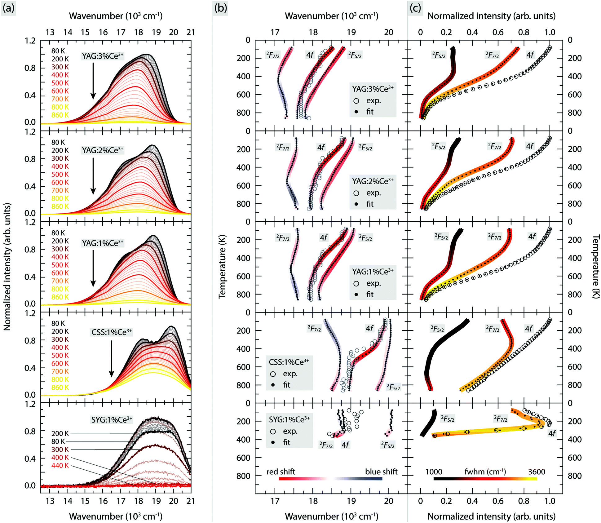 | ||
| Fig. 2 Variable temperature (a) emission spectra, (b) positions of spectral band maxima as well as their shifts with respect to the temperature (indicated by the color code bar), and (c) integrated intensity of spectral bands together with their FWHMs (indicated by the color code bar), of YAG:z% Ce3+ (z = 1, 2, and 3), CSS:1% Ce3+, and SYG:1% Ce3+. | ||
The large intensity between approximately 13![[thin space (1/6-em)]](https://www.rsc.org/images/entities/char_2009.gif) 000 and 21000 cm−1 (here labelled as the 4f band) can be assigned to Ce3+ 5d1 → 4f emissive transitions. We observe that both the position and intensity of the bands show a strong dependence on temperature and vary significantly between the five different materials. For YAG:Ce3+, the position of the emission band maximum shifts to lower wavenumbers as a function of increasing Ce3+ concentration [e.g. 18870 cm−1 (530 nm) for 1% Ce3+, 18760 cm−1 (533 nm) for 2% Ce3+, and 18480 cm−1 (541 nm) for 3% Ce3+ at T = 80 K]. Such a wavenumber shift is commonly observed for various phosphors and results from increasing radiative energy transfer from higher to lower 5d1 levels of Ce3+ ions through reabsorption processes.25,26,33–36 The lowering of the 5d1 level of Ce3+ may originate from the increased tetragonal distortions of the CeO8 moieties with increasing the Ce3+ concentration.10 By comparison, the emission band maxima of CSS:Ce3+ and SYG:Ce3+ are located at somewhat higher wavenumbers [e.g. at 19910 cm−1 (502 nm) and 18950 cm−1 (528 nm) at T = 80 K, respectively]. Thus, the color of the emitted light is predominantly in the green-yellow range for YAG:Ce3+ and in the green range for CSS:1% Ce3+ and SYG:1% Ce3+. This is further reflected by the color coordinates of the respective phosphors, as shown in the CIE 1931 diagram (Fig. 3).
000 and 21000 cm−1 (here labelled as the 4f band) can be assigned to Ce3+ 5d1 → 4f emissive transitions. We observe that both the position and intensity of the bands show a strong dependence on temperature and vary significantly between the five different materials. For YAG:Ce3+, the position of the emission band maximum shifts to lower wavenumbers as a function of increasing Ce3+ concentration [e.g. 18870 cm−1 (530 nm) for 1% Ce3+, 18760 cm−1 (533 nm) for 2% Ce3+, and 18480 cm−1 (541 nm) for 3% Ce3+ at T = 80 K]. Such a wavenumber shift is commonly observed for various phosphors and results from increasing radiative energy transfer from higher to lower 5d1 levels of Ce3+ ions through reabsorption processes.25,26,33–36 The lowering of the 5d1 level of Ce3+ may originate from the increased tetragonal distortions of the CeO8 moieties with increasing the Ce3+ concentration.10 By comparison, the emission band maxima of CSS:Ce3+ and SYG:Ce3+ are located at somewhat higher wavenumbers [e.g. at 19910 cm−1 (502 nm) and 18950 cm−1 (528 nm) at T = 80 K, respectively]. Thus, the color of the emitted light is predominantly in the green-yellow range for YAG:Ce3+ and in the green range for CSS:1% Ce3+ and SYG:1% Ce3+. This is further reflected by the color coordinates of the respective phosphors, as shown in the CIE 1931 diagram (Fig. 3).
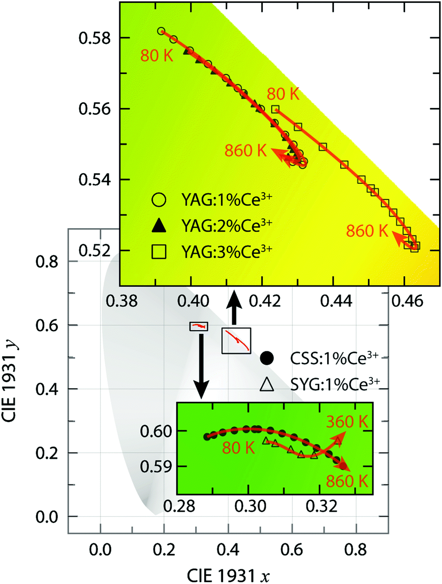 | ||
| Fig. 3 Close-up views of the CIE 1931 color coordinate diagram for YAG:z% Ce3+ (z = 1, 2, and 3) in the green-yellow region, CSS:1% Ce3+, and SYG:1% Ce3+ in the green region, upon excitation at 454 nm with varying temperature. | ||
We also observe a strong temperature dependence of the PL emission. For YAG:Ce3+, the color is systematically red-shifted as a function of increasing temperature up to about T = 740 K, whereas for even higher temperatures, the color shifts towards the blue range for all three Ce3+ concentrations. For CSS:Ce3+ and SYG:Ce3+, the color coordinates are red-shifted up to the highest measurement temperature of T = 860 K (CSS:Ce3+) and T = 360 K (SYG:Ce3+). The magnitude of the color change is for CSS:Ce3+ and SYG:Ce3+ relatively small, as it remains green color, whereas for YAG:Ce3+ it changes from greenish-yellow to yellow color.
For a more detailed analysis of the emission spectra, we find that they can be adequately fitted to two Gaussian components, for all materials and temperatures (Fig. S1 and S2, ESI†). A comparison to the literature suggests that these two components correspond to the radiative transitions from the 5d1 level to the 2F5/2 and 2F7/2 states,12,18,37,38 but, in theory, it should be noted that such radiative transitions should be manifested by a total of seven components.39 However, here, the use of more than two Gaussians is not physically sound because the emission bands are, apparently, too close to be experimentally resolved.
Fig. 2(b and c) shows the relevant fit parameters, such as (b) the peak position, and (c) integrated intensity and full width at half maximum (FWHM) of each of the two Gaussians (here called 2F5/2 and 2F7/2), as well as for their sum (4f). Here, the color on the curves in Fig. 2(b) shows the shift of the emission maximum, with red color indicating a red-shift and with blue color indicating a blue-shift. The color shifts have been estimated by taking the first derivatives of temperature dependent polynomial functions that fit the data points of the emission maxima in Fig. 2(b).
For YAG:Ce3+, both maxima (2F5/2 and 2F7/2) exhibit a strong temperature dependence. The 2F5/2 band undergoes a red-shift with increasing temperature up to around T = 800 K, while, at even higher temperatures, it undergoes a slight blue-shift. This behavior is seen for all three Ce3+ concentrations. By comparison, the 2F7/2 band exhibits a red-shift with increasing temperature up to 520 K (1% Ce3+), 530 K (2% Ce3+) and 420 K (3% Ce3+), whereas upon further temperature increase, it shows a blue-shift. For the other two garnet phosphors, CSS:Ce3+ and SYG:Ce3+, the temperature dependence of the emission maximum for the two bands is notably different. For CSS:Ce3+, the 2F5/2 band exhibits a slight albeit systematic red-shift as a function of temperature up to the highest temperature of T = 860 K, whereas the 2F7/2 band shows a blue-shift with increasing temperature from T = 80 to 500 K, after which it is red-shifted upon further temperature increase up to T = 860 K. For SYG:Ce3+, the 2F5/2 and 2F7/2 bands turn from a virtually temperature independent behavior up to T ≈ 300 K, to a red-shift with further increasing temperature up to T = 360 K. For even higher temperatures, the luminescence is too weak to be analyzed reliably.
Fig. 2(c) shows the temperature dependence of the integrated intensity and FWHM for both bands (2F5/2 and 2F7/2) as well as for the sum of their integrated intensity (4f), for all phosphors. For YAG:Ce3+, the integrated intensity of the three bands (4f, 2F5/2 and 2F7/2) is characterized by a relatively slow decrease with increasing temperature up to T = 400 K and a faster decrease for higher temperatures, for all three Ce3+ concentrations. The relatively weak decrease below T = 400 K can be related to a reduction of the absorption strength of the 4f → 5d1 transition,19,34 whereas the faster decrease at higher temperatures reflects the onset of thermal quenching of luminescence.10,34,40 For SYG:Ce3+, the integrated intensity of the 4f band exhibits a 20% increase when increasing the temperature from T = 80 K to 240 K. The origin of this intensity increase is not explicitly clear here. Some recent studies suggested that this phenomenon is likely associated with crystal defects that may act as a center to store excitation energy or charges, which can interact with the excited state of the luminescent ions (Ce3+) and further enhance the radiative emission.40–42 However, upon further temperature increase, the emission intensity decreases rapidly. At T = 400 K, it is (within error) zero. A similar trend is also observed for the 2F5/2 and 2F7/2 bands. For CSS:Ce3+, the integrated emission intensity exhibits an almost linear decrease as a function of increasing temperature up to T = 860 K. We note that this reduction in emission intensity has been related to a decrease in the absorption strength of the 4f → 5d1 transition.11
By bringing together the PL results we observe some features common to the different phosphors: the 2F7/2 band has much stronger intensity and larger FWHM than the 2F5/2 band [Fig. 2(c)], indicating that the Ce3+ emission is primarily dominated by the 5d1 → 2F7/2 transition, and the FWHMs of all bands progressively increase due to the thermal broadening effect.43
3.2 Raman spectra
Fig. 4 shows the variable temperature Raman spectra of YAG, CSS, and SYG. Considering first the lowest-temperature spectra, these are similar for the three different materials, with the number of distinguishable bands although, some of them, at different positions. Because the number of bands is related to the symmetry relations intrinsic to the garnet structure, and the chemical composition of the garnet host affects the vibrational frequencies, this is exactly what is expected. Considering next the spectra at higher temperatures, the bands show a general shift towards lower frequencies as a result of lattice expansion.10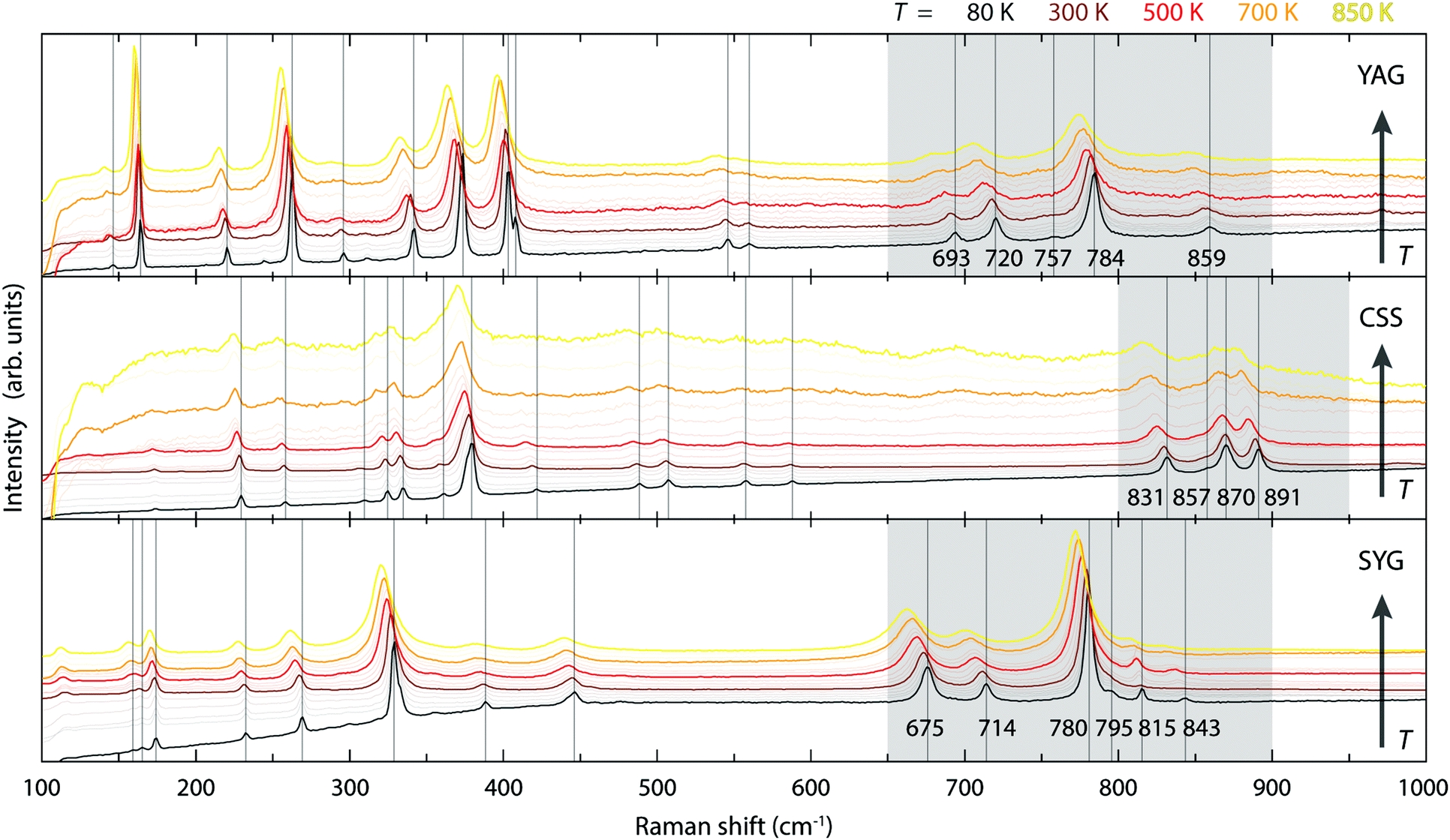 | ||
| Fig. 4 Variable temperature Raman spectra of YAG, CSS, and SYG over the range of 80–850 K. | ||
4 Discussion
4.1 The effect of the garnet host lattice on the emission color
In regard to the reason for the color difference of the emitted light between the three phosphors, it has been shown that the shorter wavelength emission for CSS:Ce3+ (green) and SYG:Ce3+ (green) as compared to YAG:Ce3+ (green-yellow) mainly originates from the higher energy of the 2Eg barycenter (in Oh notation) of the Ce3+ 5d levels (cf.Table 1).11 As the 2Eg values are mainly determined by the centroid shift εc and the cubal crystal field splitting Δ, of which Δ is inversely proportional to the Ce–O bond length (R) to a power of 5,12,16 the higher 2Eg for SYG:Ce3+ with respect to YAG:Ce3+ may thus be explained by the larger R value for SYG:Ce3+ (cf. 2.62 Å vs. 2.45 Å, see Table 1). For CSS:Ce3+ and YAG:Ce3+, the R values are, however, almost exactly the same (cf. 2.46 Å vs. 2.45 Å, see Table 1), suggesting that the magnitude of Δ may not be the main cause for the higher 2Eg value for CSS:Ce3+. In effect, this suggests that CSS:Ce3+ exhibits a smaller εc than YAG:Ce3+.| Sample | 2 E g 11 (cm−1) | R (Å) | χ A 44 | χ B 44 | χ C 44 |
χ
av
−2a |
Δ 12 11 (cm−1) | d 88/d81 |
|---|---|---|---|---|---|---|---|---|
a
 , where Nc and Na are the numbers of cations and anions, respectively, and zci and zai are their respective valence charges, and χci is the corresponding cation electronegativity, i.e. χA, χB or χC.
b Estimated from YAG (d88 = 2.859 Å and d81 = 2.899 Å) from ref. 46.
c Estimated from CSS:Ce3+ (d88 = 2.921 Å and d81 = 2.890 Å) from ref. 22.
d Estimated from SYG (d88 = 3.0834 Å and d81 = 3.0707 Å) from ref. 45. , where Nc and Na are the numbers of cations and anions, respectively, and zci and zai are their respective valence charges, and χci is the corresponding cation electronegativity, i.e. χA, χB or χC.
b Estimated from YAG (d88 = 2.859 Å and d81 = 2.899 Å) from ref. 46.
c Estimated from CSS:Ce3+ (d88 = 2.921 Å and d81 = 2.890 Å) from ref. 22.
d Estimated from SYG (d88 = 3.0834 Å and d81 = 3.0707 Å) from ref. 45.
|
||||||||
| YAG:Ce3+ | 25344 |
2.4533 | 1.22 | 1.61 | 1.61 | 0.4668 | 8135 | 0.986b |
| CSS:Ce3+ | 28908 |
2.4622 | 1.00 | 1.36 | 1.90 | 0.4217 | 12360 |
1.011c |
| SYG:Ce3+ | 28545 |
2.6245 | 0.95 | 1.22 | 2.01 | 0.4176 | 10251 |
1.004d |
ε c depends on the covalency of the Ce–O bond and the polarizability of the surrounding O anions (α).12 Generally, a high Ce–O covalency requires an extensive overlap between the Ce3+ 5d orbital and the 2p orbitals of the O ligands, which thus corresponds to short Ce–O distances (R).8,14,15 The fact that the Ce–O distances for YAG:Ce3+ and CSS:Ce3+ are comparable suggests, however, that its effect on εc is negligible compared to the effect of α, which may be approximately correlated with εc using the relation: εc ∝ α·R−6. Physically, α scales approximately linearly with χav−2, where χav is the average cation electronegativity in the material14 and as compiled for the three phosphors in Table 1. CSS:Ce3+ is characterized by a smaller χav−2 than YAG:Ce3+ (Table 1). This correlates with smaller α, which explains the higher 2Eg and the shorter wavelength emission for CSS:Ce3+, as compared to that for YAG:Ce3+.
4.2 The effect of structural dynamics on the emission color
The three effects discussed so far, i.e. the cubal crystal field splitting Δ, Ce–O covalency, and anion polarizability α, are all affected in a way that an increase of the Ce–O bond distance results in an upward-shift of the 2Eg, which in turn should be manifested as a blue-shift of the color of the emitted light. Nonetheless, the (local) lattice expansion (Fig. 4) and red-shift of the emitted light (Fig. 2 and 3) as a function of increasing temperature, suggest that a, thermally dependent, counteracting and predominating, mechanism is the main cause for the observed temperature tuning of the emission color. As the emission arises from electronic transitions from the lowest 5d level (5d1), one possible explanation for the thermally-induced red-shift may be an increase of the tetragonal crystal field splitting Δ12 (Fig. 1), due to increased tetragonal structural distortions of the CeO8 moieties. In theory, such a distortion could be purely static in nature, similarly to the effect of, e.g., cation substitution, and/or imposed by structural dynamics.10,26 In regard to the latter, Seijo et al.47 showed that the only deformations of a CeO8 moiety found to shift the lowest 5d–4f transition to lower energy (red-shift) are symmetric Ce–O bond compression and tetragonally symmetric bond bending, which are assigned to the A1g and Eg symmetries of a cubal CeO8 unit (belonging to the Oh point symmetry group), respectively. Recently, we showed for YAG that the symmetric Ce–O bond compression [the A1g stretching (S) vibration] and symmetric Ce–O bond bending [the Eg bending (B) vibration], are found primarily in the medium-to-high frequency regions of the vibrational spectra, as highlighted here by the 2D phonon decomposition map (PDM) shown in Fig. 5 (the full PDMs are shown in ref. 10). In particular, the strongest A1gS and EgB character for the YAG host can be found in the spectral range of 520–860 cm−1 for the Raman modes (R16–R19, R21, R24 and R25), and in the range of 390–860 cm−1 for the silent modes (Si27, Si41, Si43, Si51, Si52 and Si55). For CSS and SYG, the corresponding Raman modes are located in the range of i.e. 800–950 cm−1 (CSS) and 650–900 cm−1 (SYG), see Fig. 4, based on the fact that the three host materials have the same crystal structure so that, qualitatively, the (local) vibrational symmetry properties in relation to the vibrational frequency should be the same.48 It follows that the excitation of these vibrational modes should cause a red-shift of the emitted light for all the three phosphors, YAG:Ce3+, CSS:Ce3+ and SYG:Ce3+. | ||
| Fig. 5 Partial PDM focusing on the contribution of EgB and A1gS modes involving CeO8/YO8 moieties to medium-to-high frequency Raman and silent modes of YAG/YAG:Ce3+. | ||
Fig. 2(b) shows how the red-shift of the 2F7/2 band of YAG:Ce3+ occurs up to a temperature of 520 K for 1% Ce3+, 530 K for 2% Ce3+, and 420 K for 3% Ce3+, whereas the 2F5/2 band exhibits a red-shift up to about 800 K for all three Ce3+ concentrations. At even higher temperatures, the emission becomes blue-shifted and, generally, the 2F7/2 and 2F5/2 bands exhibit a red-to-blue shift with increasing temperature, however with different transition temperatures. In this context, we note also the apparent decrease in the separation between the 2F7/2 and 2F5/2 states (Fig. 6) as observed from our fitting results [Fig. 2(b)], which implies a blue-shifting effect on the 5d1–2F7/2 emission and a red-shifting effect on the 5d1–2F5/2 emission. This is in agreement and may explain the higher transition temperature observed for the 2F5/2 band. However, the physical origin of this observed energy reduction between the 2F5/2 and 2F7/2 states is at present unclear. Speculatively, it could be related to a decrease of the spin–orbit coupling strength and/or to the different temperature dependence of the electronic-vibrational transitions between the two bands, but caution should be taken that it is not just an effect of the peak deconvolution.
 | ||
| Fig. 6 Variable temperature energy difference between the maxima of the 2F5/2 and 2F7/2 bands for YAG:z% Ce3+ (z = 1, 2, and 3), CSS:1% Ce3+, and SYG:1% Ce3+, which are calculated from the fitting results shown in Fig. 2(b). Note that the results of SYG:Ce3+ at the last two points (340 K and 360 K) appear to behave unexpectedly, which may be explained by the fitting errors due to relatively low intensity of the spectra (Fig. S1, ESI†). | ||
Strikingly, the temperature range in which the transition from red-shift to blue-shift occurs, is comparable to the Debye temperature of YAG:Ce3+, ΘD > 500 K.10,33ΘD provides a measure of the temperature at which the vibrational density of states becomes fully populated, which, in our case, correspond to exactly those phonon modes that induce dynamical tetragonal distortions of the CeO8 moieties in the garnet phosphors, and it reflects the stiffness of the lattice of the material. The observation that the transition from red-shift to blue-shift occurs around ΘD suggests that when the vibrations enhancing tetragonal distortions of the CeO8 moieties are thermally fully populated, there is a counteracting effect that suppresses the degree of tetragonal distortions and effectively reverses the optical response. We attribute this counteracting effect to thermal lattice expansion, which weakens the tetragonal distortion of CeO8 since the Ce–O bonds are thermally elongated and, hence, the CeO8 moiety approaches a more cubal symmetry that reduces Δ12 (Fig. 1).23 Furthermore, we observe that the frequencies of the high-frequency modes associated with the EgB vibrations of CeO8 in the YAG host lattice, e.g., R17, R24 and R25, show a slight but significant downshift when the Ce3+ concentration increases from 1 or 2% to 3%, see ref. 10. This is in agreement with the reported ΘD that is lower for higher Ce3+ concentration10,33 and suggests that the transition temperature of the red-to-blue shift is expected to be lower for 3% Ce3+, which is as well in accordance with the observation of the shift of the band maximum of YAG:z% Ce3+ [Fig. 2(b)].
In contrast to YAG:Ce3+, CSS:Ce3+ exhibits a reversed behavior for the 2F7/2 band, as it evolves from a continuous blue-shift upon increasing temperature, up to 500 K, to a red-shift for even higher temperatures [Fig. 2(b)]. This behavior would rather suggest that the effect of the decreasing separation distance between the 2F7/2 and 2F5/2 states is stronger than the effect caused by the thermally-induced tetragonal distortions of the CeO8 moieties. This may be already hinted by the comparatively faster decrease below 500 K (Fig. 6), but is also in line with the larger ΘD for CSS:Ce3+, as compared to YAG:Ce3+, which is inferred from a simple comparison of the highest frequency of the Raman modes between the two materials (highlighted in gray areas in Fig. 4). Additionally, the relevant vibrational modes, in the range of 800–950 cm−1, appear to be more rigid against a temperature increase (Fig. 7), suggesting that they require more thermal energy to become fully activated for CSS:Ce3+ compared to YAG:Ce3+. For SYG:Ce3+, we lack emission data for T > 360 K, and therefore the effect of dynamical tetragonal distortions and the (possible) change in the separation between the 2F7/2 and 2F5/2 states cannot be adequately analyzed.
 | ||
| Fig. 7 Variation of the vibrational frequency for the Raman-active modes of YAG, CSS, and SYG, as a function of increasing temperature, revealing a more pronounced softening for YAG lattice than for CSS and SYG lattices. | ||
Turning now to a more quantitative analysis of the effect of vibrational modes on the PL emission colors, we note that, while ΘD allows one to estimate the thermal energy required for fully populating the vibrational modes inducing tetragonal distortions of the CeO8 moiety in garnet phosphors, it does not provide a measure of the vibrational amplitude, i.e. the magnitude of the tetragonal distortions. The degree of tetragonal distortions is measured here by a distortion parameter defined as the ratio of the long to short O–O distances (dl/ds) for a cubal-like CeO8/YO8 moiety, as illustrated in Fig. 8(a) for the doubly degenerated EgB vibrations in YAG:Ce3+. The so obtained dl/ds ratio as a function of excitation of the different vibrational modes reveals that strong tetragonal distortions mainly arise from modes in the wavenumber region 500–900 cm−1 and one silent mode at ≈400 cm−1 [Fig. 8(b)]. The dl/ds ratio increases by as much as ≈7% when the strongest EgB vibration is fully activated at T = ΘD, which coincides with a decrease of the energy of the maximum of the 4f emission band by, e.g., ≈820 cm−1 for YAG:1% Ce3+ [Fig. 2(b)]. Since the dl/ds values are estimated using the maximum vibrational amplitude, the effective vibrational amplitude is approximately half of the maximum, i.e. 3.5%, under the assumption that the modes are harmonic in nature. By comparison, the similar garnet phosphors Y3Al5−yGayO12:Ce3+ have been found to exhibit a red-shift of the emission maximum from 504 to 540 nm (a difference of ≈1300 cm−1) upon an increase of the analogous distortion parameter d88/d81, as defined in the inset of Fig. 8(c), by ≈4%.23 It follows that the dynamical tetragonal distortions of CeO8, as determined in this work, have a very comparable effect on the red-shift as the static tetragonal distortions of CeO8.
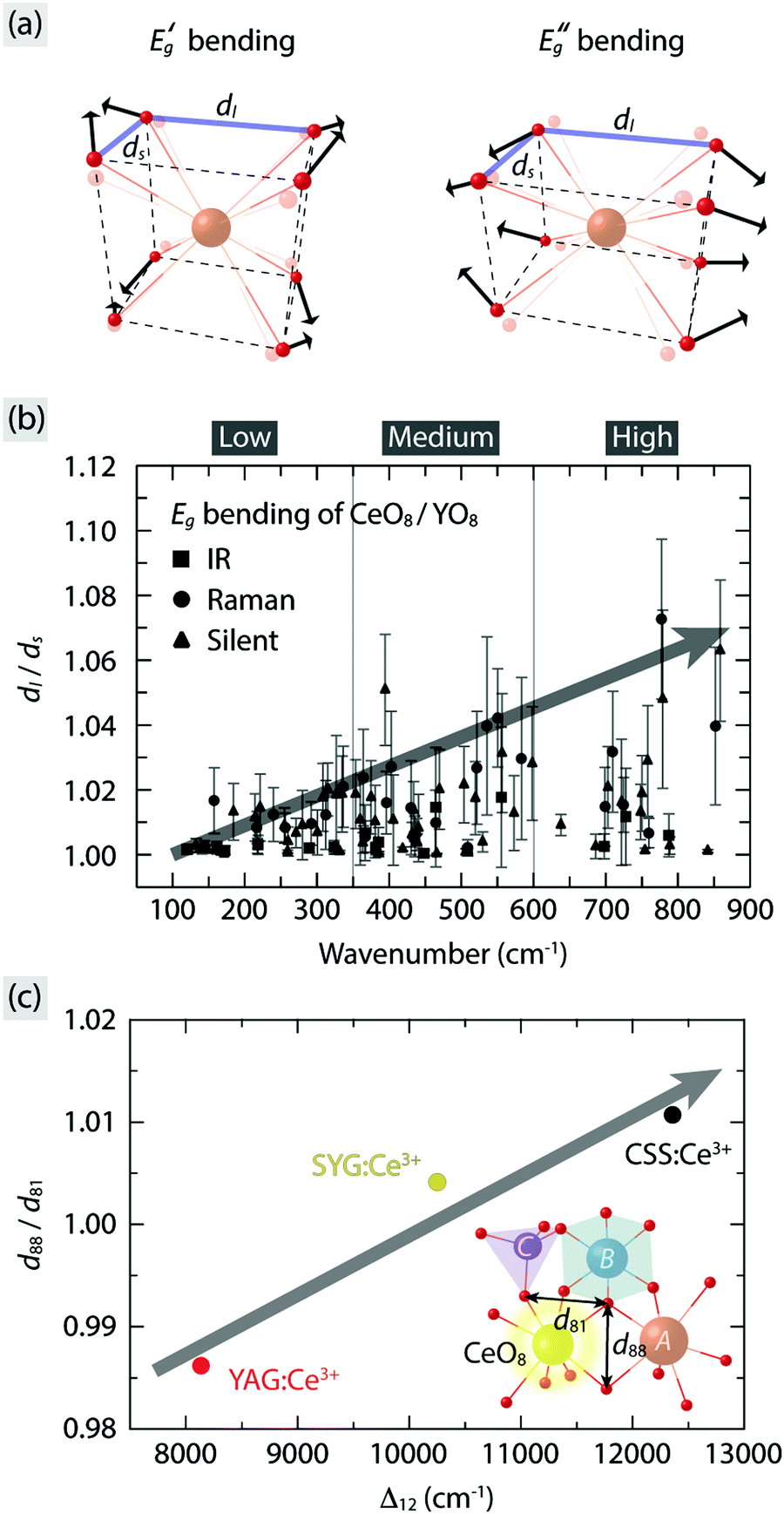 | ||
| Fig. 8 (a) Illustration of the doubly degenerate EgB modes of cubal CeO8/YO8 moieties based on their symmetry coordinates. (b) Dynamical distortion parameter (dl/ds), as marked in (a), for the EgB modes of the CeO8/YO8 moieties in YAG:Ce3+ for all vibrational modes, extracted from ref. 10. (c) Relation between the static distortion parameter (d88/d81) and the tetragonal crystal field splitting (Δ12) for YAG:Ce3+, CSS:Ce3+, and SYG:Ce3+. Inset illustrates part of polyhedral network in the garnet structure in relation to the distortion parameter d88/d81, i.e. the ratio of the two O–O distances of the dodecahedron as denoted in the figure.24,46 | ||
To compare the effect of static tetragonal distortions of CeO8 between different garnet hosts, the d88/d81 values for YAG:Ce3+, CSS:Ce3+, and SYG:Ce3+ are also calculated here using crystallographic data of respective garnet crystals (Table 1) and used as a measure for the degree of the static tetragonal distortions of CeO8. In good agreement with our spectroscopic results, the magnitude of d88/d81 is found to scale almost linearly with the magnitude of Δ12 (Table 1) for the three garnet phosphors [Fig. 8(c)]. It is worth noting that an increase of d88/d81 by 2% leads to an increase of Δ12 by ≈4200 cm−1 (Table 1), which suggests that the control of the local (tetragonal) lattice distortions around Ce3+ through complete cation co-substitution affects significantly the color of the PL.
5 Conclusions
In conclusion, we have shown that the red-shift of the PL emission as a function of increasing temperature generally observed in YAG:Ce3+, CSS:Ce3+, and SYG:Ce3+ garnet phosphors is the result of thermally activated dynamical tetragonal distortions of the CeO8 moieties. The relevant vibrational modes exhibiting this type of dynamical lattice distortions are mainly associated with symmetric Eg bending of CeO8 with relatively high vibrational frequencies of the lattice modes. The frequency (rigidity) as well as the amplitude (degree of the tetragonal distortion) of these vibrational modes determines the magnitude of the red-shift at a given temperature, which is influenced by the Ce3+ dopant concentration and the chemical compositions of the garnet host. The reversal of wavelength shift, as observed in YAG:Ce3+ with increasing temperature up to around 500 K, occurs when these modes are fully populated. At higher temperatures, the effect of thermal lattice expansion becomes overwhelming, which leads to a more cubal-like local environment of the CeO8 moieties. Since this behavior is the result of the symmetry relations intrinsic to the garnet structure, the mechanisms described here can be expected to be generally applicable to materials of this type.Conflicts of interest
There are no conflicts to declare.Acknowledgements
M. K. thanks the Swedish Research Council Formas for funding (Grant No. 2013-1723). The group of R. Seshadri, UCSB, is thanked for providing the series of YAG:Ce3+ samples. The group of M. Bettinelli, University of Verona, is thanked for the synthesis of the CSS:Ce3+ and SYG:Ce3+ samples and for fruitful discussions.References
- S. Pimputkar, J. S. Speck, S. P. DenBaars and S. Nakamura, Nat. Photonics, 2009, 3, 180–182 CrossRef CAS.
- Y.-C. Lin, M. Karlsson and M. Bettinelli, Top. Curr. Chem., 2016, 374, 1–47 CrossRef CAS PubMed.
- P. F. Smet, A. B. Parmentier and D. Poelman, J. Electrochem. Soc., 2011, 158, R37–R54 CrossRef CAS.
- M. R. Krames, O. B. Shchekin, R. Mueller-Mach, G. O. Mueller, L. Zhou, G. Harbers and M. G. Craford, J. Disp. Technol., 2007, 3, 160–175 CAS.
- S. Ye, F. Xiao, Y. X. Pan, Y. Y. Ma and Q. Y. Zhang, Mater. Sci. Eng., R, 2010, 71, 1–34 CrossRef.
- C. C. Lin and R.-S. Liu, J. Phys. Chem. Lett., 2011, 2, 1268–1277 CrossRef CAS PubMed.
- Z. Xia and A. Meijerink, Chem. Soc. Rev., 2017, 46, 275–299 RSC.
- X. Qin, X. Liu, W. Huang, M. Bettinelli and X. Liu, Chem. Rev., 2017, 117, 4488–4527 CrossRef CAS PubMed.
- S. Geller, Z. Kristallogr., 1967, 125, 1–47 CrossRef CAS.
- Y.-C. Lin, P. Erhart, M. Bettinelli, N. C. George, S. F. Parker and M. Karlsson, Chem. Mater., 2018, 30, 1865–1877 CrossRef CAS.
- S. K. Sharma, Y.-C. Lin, I. Carrasco, T. Tingberg, M. Bettinelli and M. Karlsson, J. Mater. Chem. C, 2018, 6, 8923–8933 RSC.
- N. C. George, K. A. Denault and R. Seshadri, Annu. Rev. Mater. Res., 2013, 43, 481–501 CrossRef CAS.
- P. Dorenbos, J. Lumin., 2013, 134, 310–318 CrossRef CAS.
- P. Dorenbos, Phys. Rev. B: Condens. Matter Mater. Phys., 2002, 65, 235110 CrossRef.
- P. Dorenbos, J. Lumin., 2002, 99, 283–299 CrossRef CAS.
- P. D. Rack and P. H. Holloway, Mater. Sci. Eng., R, 1998, 21, 171–219 CrossRef.
- E. G. Rogers and P. Dorenbos, J. Lumin., 2014, 155, 135–140 CrossRef CAS.
- A. Kaminska, A. Duzynska, M. Berkowski, S. Trushkin and A. Suchocki, Phys. Rev. B: Condens. Matter Mater. Phys., 2012, 85, 155111 CrossRef.
- D. Robbins, J. Electrochem. Soc., 1979, 126, 1550–1555 CrossRef CAS.
- Z. Xia and Q. Liu, Prog. Mater. Sci., 2016, 84, 59–117 CrossRef CAS.
- A. A. Setlur, W. J. Heward, Y. Gao, A. M. Srivastava, R. G. Chandran and M. V. Shankar, Chem. Mater., 2006, 18, 3314–3322 CrossRef CAS.
- F. Pan, M. Zhou, J. Zhang, X. Zhang, J. Wang, L. Huang, X. Kuang and M. Wu, J. Mater. Chem. C, 2016, 4, 5671–5678 RSC.
- J. L. Wu, G. Gundiah and A. Cheetham, Chem. Phys. Lett., 2007, 441, 250–254 CrossRef CAS.
- A. Kalaji, P. J. Saines, N. C. George and A. K. Cheetham, Chem. Phys. Lett., 2013, 586, 91–96 CrossRef CAS.
- A. Setlur and A. Srivastava, Opt. Mater., 2007, 29, 1647–1652 CrossRef CAS.
- C.-C. Chiang, M.-S. Tsai and M.-H. Hon, J. Electrochem. Soc., 2008, 155, B517–B520 CrossRef CAS.
- Q. Shao, Y. Dong, J. Jiang, C. Liang and J. He, J. Lumin., 2011, 131, 1013–1015 CrossRef CAS.
- T. Y. Tien, E. F. Gibbons, R. G. DeLosh, P. J. Zacmanidis, D. E. Smith and H. L. Stadler, J. Electrochem. Soc., 1973, 120, 278–281 CrossRef CAS.
- Y. X. Pan, W. Wang, G. K. Liu, S. Skanthakumar, R. A. Rosenberg, X. Z. Guo and K. K. Li, J. Alloys Compd., 2009, 488, 638–642 CrossRef CAS.
- Y. Kanke and A. Navrotsky, J. Solid State Chem., 1998, 141, 424–436 CrossRef CAS.
- H. Ji, L. Wang, M. S. Molokeev, N. Hirosaki, R. Xie, Z. Huang, Z. Xia, M. Otmar, L. Liu and V. V. Atuchin, J. Mater. Chem. C, 2016, 4, 6855–6863 RSC.
- Z. Xia, C. Ma, M. S. Molokeev, Q. Liu, K. Rickert and K. R. Poeppelmeier, J. Am. Chem. Soc., 2015, 137, 12494–12497 CrossRef CAS PubMed.
- N. C. George, A. J. Pell, G. Dantelle, K. Page, A. Llobet, M. Balasubramanian, G. Pintacuda, B. F. Chmelka and R. Seshadri, Chem. Mater., 2013, 25, 3979–3995 CrossRef CAS.
- V. Bachmann, C. Ronda and A. Meijerink, Chem. Mater., 2009, 21, 2077–2084 CrossRef CAS.
- V. Bachmann, C. Ronda, O. Oeckler, W. Schnick and A. Meijerink, Chem. Mater., 2008, 21, 316–325 CrossRef.
- Y. Q. Li, N. Hirosaki, R. J. Xie, T. Takeda and M. Mitomo, Chem. Mater., 2008, 20, 6704–6714 CrossRef CAS.
- J. Brgoch, C. K. H. Borg, K. A. Denault, A. Mikhailovsky, S. P. DenBaars and R. Seshadri, Inorg. Chem., 2013, 52, 8010–8016 CrossRef CAS.
- M. Grinberg, J. Barzowska, Y. R. Shen, R. S. Meltzer and K. L. Bray, Phys. Rev. B: Condens. Matter Mater. Phys., 2004, 69, 205101 CrossRef.
- J. Gracia, L. Seijo, Z. Barandiarán, D. Curulla, H. Niemansverdriet and W. van Gennip, J. Lumin., 2008, 128, 1248–1254 CrossRef CAS.
- Y.-C. Lin, M. Bettinelli and M. Karlsson, Chem. Mater. DOI:10.1021/acs.chemmater.8b05300.
- Y. H. Kim, P. Arunkumar, B. Y. Kim, S. Unithrattil, E. Kim, S.-H. Moon, J. Y. Hyun, K. H. Kim, D. Lee, J.-S. Lee and W. B. Im, Nat. Mater., 2017, 16, 543–550 CrossRef CAS PubMed.
- J. Qiao, L. Ning, M. S. Molokeev, Y.-C. Chuang, Q. Liu and Z. Xia, J. Am. Chem. Soc., 2018, 140, 9730–9736 CrossRef CAS PubMed.
- B. Henderson and G. Imbusch, Optical Spectroscopy of Inorganic Solids, Clarendon Press, Oxford, 2006 Search PubMed.
- A. Allred, J. Inorg. Nucl. Chem., 1961, 17, 215–221 CrossRef CAS.
- S. J. Marin, M. O'Keeffe, V. G. Young and R. B. V. Dreele, J. Solid State Chem., 1991, 91, 173–175 CrossRef CAS.
- A. Nakatsuka, A. Yoshiasa and T. Yamanaka, Acta Crystallogr., Sect. B: Struct. Sci., 1999, 55, 266–272 CrossRef.
- L. Seijo and Z. Barandiarán, Opt. Mater., 2013, 35, 1932–1940 CrossRef CAS.
- K. Nakamoto, Infrared and Raman Spectra of Inorganic and Coordination Compounds, Theory and Applications in Inorganic Chemistry, Wiley, 2008 Search PubMed.
Footnote |
| † Electronic supplementary information (ESI) available. See DOI: 10.1039/c9tc01244c |
| This journal is © The Royal Society of Chemistry 2019 |