
 Open Access Article
 This Open Access Article is licensed under a
 Creative Commons Attribution 3.0 Unported Licence
From scrap metal to highly efficient electrodes: harnessing the nanotextured surface of swarf for effective utilisation of Pt and Co for hydrogen production†
Madasamy
Thangamuthu
 *a,
Emerson C.
Kohlrausch
a,
Ming
Li
b,
Alistair
Speidel
b,
Adam T.
Clare
b,
Richard
Plummer
a,
Paul
Geary
c,
James W.
Murray
b,
Andrei N.
Khlobystov
*a and
Jesum
Alves Fernandes
*a
*a,
Emerson C.
Kohlrausch
a,
Ming
Li
b,
Alistair
Speidel
b,
Adam T.
Clare
b,
Richard
Plummer
a,
Paul
Geary
c,
James W.
Murray
b,
Andrei N.
Khlobystov
*a and
Jesum
Alves Fernandes
*a
aSchool of Chemistry, University of Nottingham, University Park, Nottingham NG7 2RD, UK. E-mail: madasamy.thangamuthu1@nottingham.ac.uk; andrei.khlobystov@nottingham.ac.uk; jesum.alvesfernandes@nottingham.ac.uk
bFaculty of Engineering, University of Nottingham, University Park, Nottingham NG7 2RD, UK
cAqsorption, 15A Great Northern Way, Netherfield, Nottingham NG4 2HD, UK
First published on 16th April 2024
Abstract
Hydrogen is considered to be the key element to achieving climate neutrality, leading to a massive demand for electrocatalysts. This work explores the transformation of metal waste into active and stable electrode materials for water splitting by modifying the surface through atomic deposition of platinum (Pt) and cobalt (Co). Our study finds that with the addition of only 28 μg cm−2 of Pt and 30 μg cm−2 of Co to metal waste, high-performance electrolysis can be achieved. We investigated discarded stainless-steel (SST), titanium (Ti), and nickel (Ni) alloys and found that they had nanotextured surfaces, consisting of 10–50 nm wide grooves, which offered an excellent platform for effective bonding of Pt or Co atoms. We demonstrate a strong synergistic relationship between the metal of the swarf surface and the metal of catalytically active centers, such that only some combinations lead to effective electrocatalysts. Furthermore, we discovered that the surface density of atomically deposited Pt or Co has a profound impact on the nanoscale morphology of the active centers, providing a mechanism for the optimization of electrocatalytic characteristics. For instance, the optimal Pt loading (28 μg cm−2) on Ti swarf yields 5–20 nm Pt nanoparticles within the grooves with exceptional hydrogen evolution reaction (HER) activity. Similarly, the optimal surface density of Co (30 μg cm−2) on Ni swarf generates ∼100 nm interlinked flakes of Co(OH)2 with outstanding oxygen evolution reaction (OER) performance. Combining these best electrodes in a full-cell electrolyser resulted in a current density of 40 mA cm−2 at 1.6 V vs. RHE and the rates of H2 and O2 production of 22.09 and 10.75 mmol min−1, respectively, with 100% faradaic efficiency with no decrease in activity in 24 hours. This study opens the door to more sustainable electrode fabrication and effective hydrogen production in alkaline water electrolysis.
Introduction
The global manufacturing industry generates a substantial amount of low-value metal waste primarily in the form of chips and swarf produced from mechanical machining processes such as turning, milling and drilling.1 Unfortunately, a significant portion of these commercially valuable metals is disposed of in large quantities and inadequately recycled or reused. Full recycling may be prohibitively expensive or impractical. On the other hand, the iron and steel manufacturing industry consumes approximately 8% of the world's energy,2 with its processes and energy-related emissions contributing to 7.2% of anthropogenic CO2 emissions.3 Similarly, titanium (Ti) and its alloys generate significant volumes of waste material relative to their initial feedstock size.4 Particularly, more than 80% of Ti waste originates from the aerospace industry during the conventional machining of Ti fan blades.5 Consequently, the direct reuse and re-purposing of metal wastes are critically essential endeavours, crucial for reducing the environmental impact, addressing the global energy demand, and advancing towards a circular economy.Recently, there has been a notable utilisation of small chip metal waste as a viable substitute for powder in laser additive manufacturing.6 Similarly, large swarf-type feedstocks and soft metals like aluminium have proven to be effective materials for solid-state sintering.7,8 Surprisingly, the unique surface and geometrical characteristics of the swarf have remained largely unexplored in the realm of heterogeneous catalysis. Spiral-turned metal swarf, characterised by its exceptional surface area-to-weight ratio, holds significant promise in electrocatalysis to increase reaction efficiency. Prior research has demonstrated the fabrication of a 3D-printed helical-shaped stainless steel (SST) electrode for the oxygen evolution reaction (OER) by depositing an oxidation cocatalyst, IrO2.9 However, this 3D printing method is slow and lacks scalability for producing helical shapes, which is unlikely to make a meaningful industrial impact. In this work, for the first time, we show that the naturally occurring helical shape and textured surface of the waste metal swarf could offer superior support for electrocatalysts (Scheme 1).
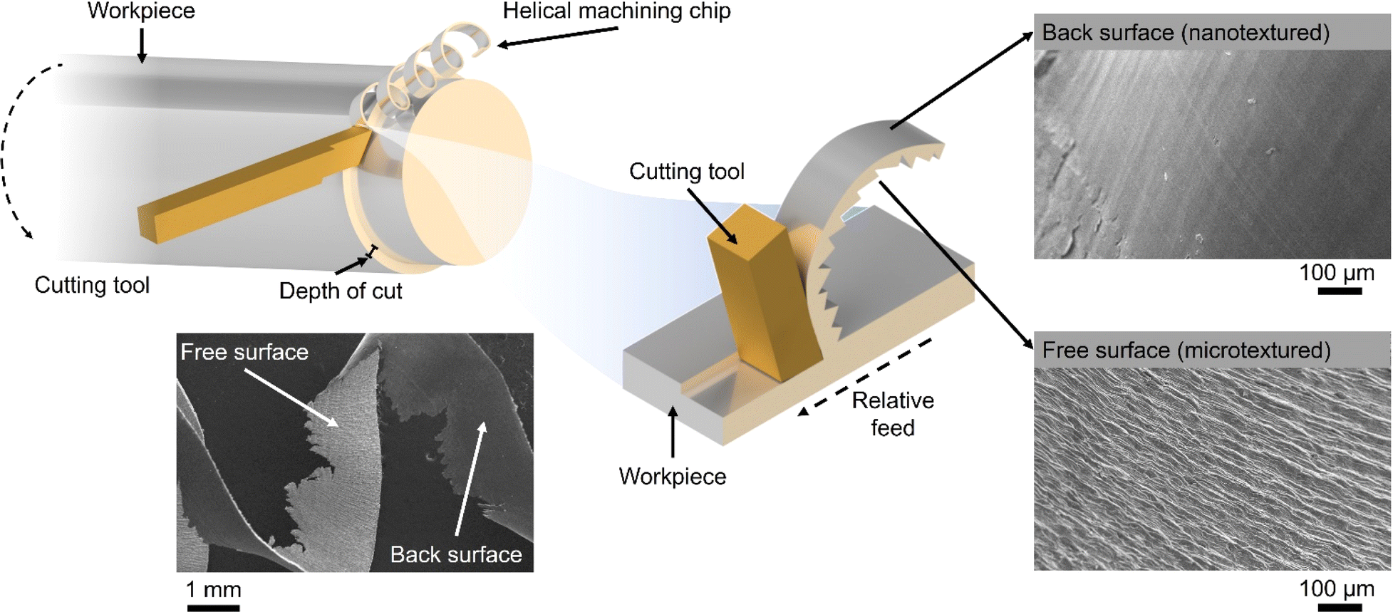 | ||
| Scheme 1 Schematic representation of the swarf preparation showing its nano–micro-textured surface. In the bottom left a photo of bulk Ti swarf waste after machining; a scanning electron microscopy image and a photo of a single Ti swarf (used in this work), respectively. | ||
In this work, we demonstrate that the swarf has a naturally formed nanotexture which allows effective adsorption and stabilisation of catalytic nanostructures, Pt and Co, to harness their electrocatalytic properties in the hydrogen evolution reaction (HER) and oxygen evolution reaction (OER) under alkaline conditions. We investigate the surface density of Pt and Co atoms deposited onto the swarf and its impact on the nanoscale morphology of the catalytically active centres, which is correlated with the electrocatalytic properties. The relationship between the nature of the metal of the swarf with the metal of catalytically active centres appears to play a significant role in the electrochemical performance of the swarf electrodes with Pt–Ti and Co–Ni offering the lowest overpotentials for the HER and OER respectively. Our method of direct deposition of Pt or Co atoms onto the swarf surface not only eliminates the need for solvents or reagents10–12 but also allows HER activity to be achieved with one-tenth the amount of Pt loading (0.028 mg cm−2) as compared to state-of-the-art Pt/C (0.1–0.6 mg cm−2) commercial catalysts.13,14 Establishing the structure–property relationship enabled us to combine the best of swarf-based electrodes in a full-cell electrolyser to achieve H2 (22.09 mmol min−1) and O2 (10.75 mmol min−1) evolution with a 2![[thin space (1/6-em)]](https://www.rsc.org/images/entities/char_2009.gif) :1 ratio at 1.6 V vs. RHE with 100% faradaic efficiency.
:1 ratio at 1.6 V vs. RHE with 100% faradaic efficiency.
Results and discussion
First, we assessed the hydrogen evolution reaction (HER) and oxygen evolution reaction (OER) activities of the bare titanium (Ti), stainless steel (SST) and nickel (Ni) swarf (the composition of each alloy can be found in Table S1†) electrodes in 1 M KOH (5.6%) solution under an Ar atmosphere. SST showed the highest HER activity followed by Ni and then Ti (Fig. 1a). The poor HER activity of the bare Ti and Ni alloys (see the composition in Table S1†) as electrodes can be explained by the fact that Ti and Ni form a more stable metal hydride bond compared to SST leading to surface poisoning and hence less current density15 and for Ti also due to the formation of a TiO2 layer (Fig. S1a†). We also evaluated the OER activity of these swarf electrodes and observed the best performance from the bare Ni electrode which is due to the formation of Ni(OH)2 (Fig. 1b and S1c†), which agrees well with earlier reports.16–19 Bare Ti shows poor OER activity due to the formation of a TiO2 layer, as mentioned previously.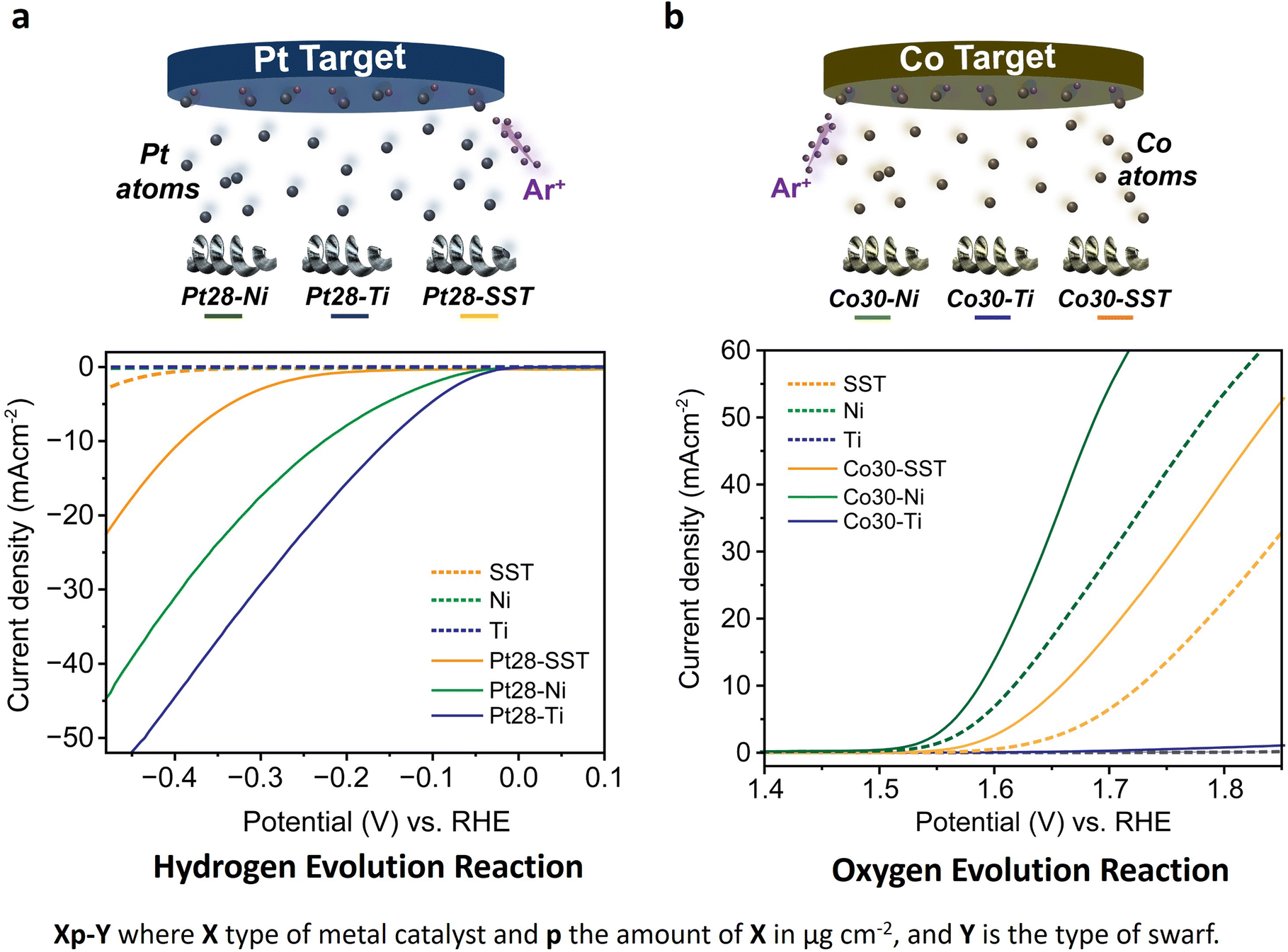 | ||
| Fig. 1 (a) Schematic representation of Pt deposition on Ni, Ti, and SST swarf using atom dispersion, and their hydrogen evolution activities measured in 1 M KOH solution at a scan rate of 10 mV s−1vs. Hg/HgO. The solid orange, green, and blue lines represent the HER activities of the SST, Ni, and Ti swarf electrodes in the presence of Pt and the corresponding dashed lines represent the activities without Pt. (b) Schematic representation of Co deposition on Ni, Ti, and SST swarf using atom dispersion, and their OER activities measured in 1 M KOH solution at a scan rate of 10 mV s−1vs. Hg/HgO (the RHE values were obtained using the Nernst equation). | ||
To further enhance the HER and OER activity of the Ti, SST and Ni swarf electrodes, we deposited Pt and Co, respectively, in atomic form on swarf surfaces which then self-assembled as nanostructures due to the metal atoms' surface diffusion.20 The flux of Pt and Co atoms was provided by magnetron sputtering for 90 seconds yielding their loadings of 28 μg cm−2 and 30 μg cm−2, respectively (Fig. 1, Table S2†). Hereafter, the swarf electrodes loaded with an electrocatalyst will be denoted as Xp–Y, where X is the electrocatalyst, p represents the surface density in μg cm−2 of X and Y is the swarf material. Then, we assessed the HER and OER activities of the Pt and Co-loaded swarf electrodes under similar conditions. The addition of Pt and Co electrocatalysts in their atomic form on the bare metal swarf electrodes significantly improved the HER and OER activities (Fig. 1). In the case of Pt, the addition of 28 μg cm−2 on SST, Ti and Ni swarf has changed their order of activity in the HER, such that the Pt28–Ti electrode exhibited the highest HER activity followed by Pt28–Ni and then Pt28–SST (Fig. 1a). The changes in relative HER activities are dramatic with the Ti and Ni swarf increasing their activity by a factor of 60 while that of SST only increases by a factor of 4 for the same loading of Pt.
To better understand this HER performance, we analysed the charge-transfer resistance and reaction kinetics using electrochemical impedance spectroscopy and Tafel analysis of the Pt28–Ti, Pt28–Ni and Pt28–SST. The Nyquist plot obtained for Pt28–Ti shows a relatively small charge-transfer resistance of 12.7 Ω with a slight increase to 14.5 Ω for Pt28–Ni whereas Pt28–SST shows a much higher resistance of 79.0 Ω (Table S3†) suggesting that the lower charge-transfer resistance of the Pt28–Ti at the electrode–electrolyte interface boosts the HER activity. Furthermore, Pt28–Ti exhibited a Tafel slope of 103 mV dec−1, whereas Pt28–Ni and Pt28–SST displayed a slope of 123 mV dec−1 and 153 mV dec−1 respectively (Fig. S2†) which indicates more favourable reaction kinetics for Pt28–Ti corroborating with the EIS and HER results. We have also normalised the catalytic performance of Pt28–Ti, Pt28–Ni and Pt28–SST by their electrochemically active surface area (ECSA) which confirmed that active sites on Pt28–Ti are the most active (Fig. S3†). In addition, Pt28–Ti showed a very low overpotential (0.183 V) compared to Pt28–Ni (0.23 V) and Pt28–SST (0.390 V) (Fig. S4†), suggesting a strong metal–support interaction (SMSI) between the Pt and Ti surface consistent with the literature.21,22 It is important to mention that our study is focused on alloy waste metals of industrial relevance which consist of several elements; for instance, the Inconel 625 alloy contains Cr, Mo, Fe and Nb in addition to Ni (Table S1†). Therefore, these results cannot be directly compared with the literature based on pure Pt/Ni.23,24 Subsequently, we conducted long-term durability tests on the electrodes using chronoamperometry in 1 M KOH at a constant potential of −0.5 V vs. RHE. All the swarf electrodes exhibited remarkable stability, with virtually no changes in current observed for Pt28–Ti and Pt28–Ni, and only a modest ∼15% decrease observed for Pt28–SST after a 24 hour reaction (Fig. S5†).
We assessed the HER activities of standard Pt plate, graphite, Pt28–graphite, glassy carbon, and Pt28–glassy carbon electrodes, and compared them with those of Pt28–Ti, Pt28–Ni, and Pt28–SST (Fig. S4a†). At 10 mA cm−2, the overpotential of the Pt28–Ti swarf electrode was 0.183 V, which is only 30 mV higher than that of the standard Pt plate (0.153 V), while Pt28–Ni and Pt28–SST displayed overpotentials of 0.230 V and 0.390 V, respectively (Fig. S4b†). Similarly, the control electrodes like Pt28–graphite and Pt28–glassy carbon electrodes also exhibited the high overpotentials of 0.340 V and 0.410 V, respectively. This underscores that Pt–Ti stands out as an exceptional electrocatalyst with only 28 μg cm−2 of Pt, which is equivalent to 50 atomic monolayers, if no nano–micro-textured surface is considered, yet closely approaching the performance of commercial bulk Pt electrodes.
Following a similar strategy, we examined the OER performance of Co30–Ti, Co30–Ni and Co30–SST under the same experimental conditions. The deposited Co yields Co(OH)2 on the surface of the swarf electrodes through natural oxidation in the KOH electrolyte under positive potentials, significantly enhancing O2 evolution compared to the bare swarf electrodes (Fig. 1b and S1d†). In contrast to the HER, the addition of Co to the different types of swarf did not change the trend of relative OER activities with the Co30–Ni electrode exhibiting the highest OER followed by Co30–SST and then much lower Co30–Ti. At 10 mA cm−2, the overpotential of the Co30–Ni electrode was 0.350 V, while for Co30–SST it was at 0.430 V (Fig. S6†). The superior performance of Co30–Ni is likely due to the fact that the bare Ni swarf has an OER activity of its own, which is further enhanced by the formation of nano Co(OH)2 clusters. Interestingly, replacing Co with nearly the same amount of Ru (25 μg cm−2) did not improve the performance of the OER (Fig. S7†). This combined with the cost-effectiveness of Co makes the Co30–Ni electrodes exceptionally attractive for large-scale water electrolysers.
We then evaluated the impact of the surface density of atomically deposited Pt and Co onto Ti and Ni swarf, respectively, as they showed the best performance for the HER and OER. We found that decreasing or increasing the Pt loading onto Ti swarf to 13 μg cm−2 or 60 μg cm−2, in Pt13–Ti and Pt60–Ti, respectively, had a negative impact on the electrocatalytic performance of the swarf electrodes, as compared to that of Pt28–Ti (Fig. 2a). This suggests that there is an optimal loading of catalytic centres on the swarf material. A similar trend was evident for SST and Ni swarf electrodes, with their HER activities following the order of Pt28–SST > Pt60–SST > Pt13–SST (Fig. S8a†), and Pt28–Ni > Pt60–Ni > Pt13–Ni (Fig. S8b†). A similar analysis of the Co loading onto the Ni swarf electrode revealed that the medium loading in Co30–Ni demonstrated better OER activity compared to that in Co15–Ni and Co68–Ni (Fig. 2b). To reveal the underlying mechanisms responsible for the observed trends, we investigated the influence of the surface density of Pt and Co electrocatalytic centres on charge transfer by obtaining Nyquist plots. Pt–Ti swarf exhibited notable variations: the overall resistance Rp value for the Pt28–Ti electrode amounted to 12.7 Ω, which was approximately 10% that of the Pt13–Ti electrode and about 50% lower than that of the Pt60–Ti electrode. This observation suggests that Pt28–Ti exhibits superior charge transfer characteristics, implying lower charge transfer resistance at the electrode–electrolyte interface (Fig. 2c). Similarly, we evaluated the charge-transfer resistance for the most efficient OER electrode. The Nyquist plots generated for Ni swarf electrodes modified with Co atoms exhibited marked disparities with the Co30–Ni electrode showing less overall resistance of 2.5 Ω, compared to the Co15–Ni (4 Ω) and Co68–Ni (3.6 Ω) electrodes (Fig. 2d and Table S3†). These findings strongly support that the HER and OER current densities are strongly dependent on the loading of catalytic centres.
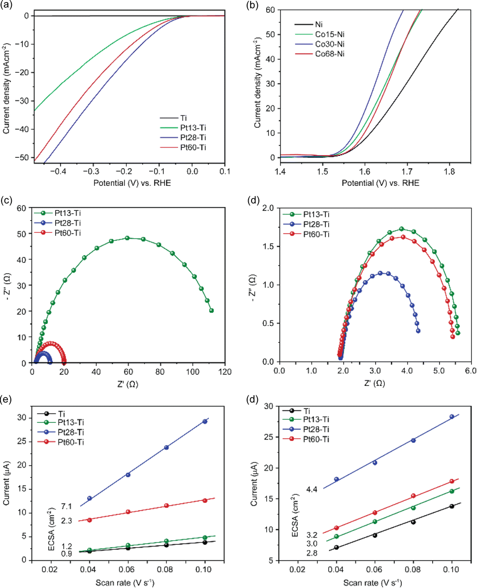 | ||
| Fig. 2 (a) Hydrogen evolution activities of bare Ti, Pt13–Ti, Pt28–Ti, and Pt60–Ti electrodes, (b) oxygen evolution activities of bare Ni, Co15–Ni, Co30–Ni, and Co68–Ni electrodes, measured in 1 M KOH at a scan rate of 10 mV s−1vs. Hg/HgO, (c and d) Nyquist plots of Ti swarf electrodes at different Pt loadings and Ni swarf electrodes at different loadings of Co, respectively. (e and f) The double-layer charging currents measured at 0.1 V vs. Hg/HgO were plotted against the scan rates, with the ECSA values given for each sample on the left hand. | ||
To further confirm this hypothesis, we investigated the electrochemical active surface area (ECSA), a key parameter for the electrocatalyst activity, by the double-layer capacitance approach which is the most suitable for the intricate composition of Ti and Ni swarf electrodes containing multiple metals (see details in ESI Fig. S9†).25,26 The calculated ECSA for the best-performing swarf electrode, Pt28–Ti, was found to be 7.1 cm2, as compared to 2.3, 1.2 and 0.9 cm2 for Pt60–Ti, Pt13–Ti and bare Ti respectively (Fig. 2e and Table S4†). This further demonstrates the importance of the optimal surface density of the electrocatalytically active centres on the swarf. Similarly, we examined the ECSA of the OER swarf electrodes using the same approach as described earlier (Fig. 2f). The ECSA for the Co30–Ni electrode was calculated to be 4.34 cm2, which is approximately 1.5 times and 1.3 times higher than those of the Co15–Ni and Co68–Ni electrodes, respectively (Table S4†). Considering the geometric surface area of the swarf in our experiments is about 1 cm2, the optimal loading of catalytic centres allows effective utilisation of swarf nanotexture.
To link the electrochemical parameters with the nanoscale morphology of the swarf electrodes, we have performed a systematic field emission gun scanning electron microscopy (FEG-SEM) imaging for all Pt–Ti and Co–Ni electrodes (Fig. 3). The blank swarf appears to have a highly textured outer surface of the spiral, featuring parallel 10–50 nm wide grooves running along the primary axis of the spiral with the Ni swarf showing the same features (Fig. S10†). Upon atomic deposition of Pt and Co, the surface of the swarf became decorated with nanostructures of Pt and Co, as evident from both FEG-SEM images (Fig. 3) and EDX spectra (Fig. S11†). The size and morphology of these nanostructures appear to be strongly dependent on the catalyst loading. For example, Pt13–Ti contains mainly Pt nanoclusters as it cannot be observed by FEG-SEM due to its resolution limitations (Fig. 3a). Doubling the amount of platinum in Pt28–Ti resulted in increased coverage of the swarf surface with Pt and the formation of 5–20 nm particles decorating the grooves (Fig. 3b). Doubling the loading once again in Pt60–Ti led to the formation of 3D diffuse agglomerates of Pt nanoparticles with a grain size of >100 nm (Fig. 3c). Variation of Co loading on Ni swarf had a similarly striking effect on the electrocatalyst morphology. FEG-SEM imaging of Co15–Ni revealed that the texture of the swarf surface was unchanged but became covered with rods ∼10 nm in diameter (Fig. 3d), which is attributed to Co(OH)2 consistent with Co oxidation after atomic deposition.27,28 Doubling the Co amount in Co30–Ni increased the coverage of the swarf surface with Co(OH)2 forming a network of interlinking flakes ∼100 nm in diameter (Fig. 3e). Doubling it once again in Co68–Ni resulted in the formation of Co(OH)2 film with 100–500 nm wide flakes protruding from it on the swarf surface (Fig. 3f). Therefore, FEG-SEM comparative analysis for different loadings of electrocatalytic metals suggests that a balance between coverage and nanostructure size is crucial for high HER and OER performance.
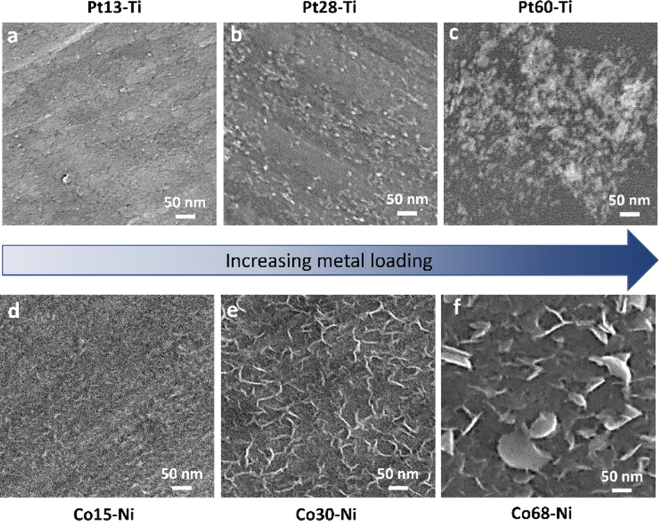 | ||
| Fig. 3 SEM images of (a) Pt13–Ti, (b) Pt28–Ti, (c) Pt60–Ti, (d) Co15–Ni, (e) Co30–Ni, and (f) Co68–Ni electrodes. | ||
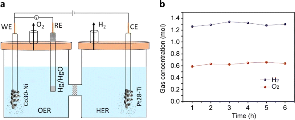
To assess the practical applicability of the extensively studied HER and OER half-cells, we selected the best-performing Pt28–Ti and Co30–Ni electrodes as the cathode and anode, respectively, in a full-cell electrolyser setup. These electrodes were separated by an anion exchange membrane (Fig. 4a and S12†) and immersed in a degassed 1 M KOH solution. Water electrolysis was initiated by applying a voltage of 1.6 V vs. RHE to the anode using chronoamperometry. Significant evolution of H2 and O2 gases was observed in the cathodic and anodic compartments (Video S1†) during the reaction, accompanied by a current density of 40 mA cm−2. The rates of H2 and O2 evolution were measured at 1.3 mol h−1 and 0.64 mol h−1, respectively (Fig. 4b), reaching the 2:1 ratio required for efficient water splitting. Importantly, we achieved a 100% faradaic efficiency for both H2 and O2 evolution, indicating the remarkable efficiency of the swarf-based cathode and anode in this setup. The HER and OER activities of the present work were also compared with earlier reports (Tables S5 and S6†).
 | ||
| Fig. 4 (a) Schematic diagram illustrating a full-cell alkaline water electrolyser with swarf electrodes Pt28–Ti and Co30–Ni operating as electrocatalysts for the HER and OER, respectively. (b) Evolution of oxygen and hydrogen from the cell over time. | ||
The obtained superiority primarily stems from the swarf's surface roughness and the resulting large active surface area, which fosters enhanced interaction with catalytic centres and the electrolyte. The relationship between the nature of the metal of the swarf and the metal of catalytically active centres appears to play a significant role in the electrochemical performance of the swarf electrodes with Pt28–Ti and Co30–Ni offering the best HER and OER activities, respectively (Fig. 5a). We found that even subtle variations in Ni alloys appear to impact the quality of Co(OH)2 electrocatalysis, with Inconel 625 proving to be a more active electrode for the OER compared to Inconel 718 (Fig. S13†). The synergistic relationship between the swarf and catalytic centres may arise from chemistry. For example, the notable enhancement in OER activity observed with Ni swarf combined with Co(OH)2 catalytic centres may result from the synergistic catalytic effect of in situ-formed Ni oxides under high positive oxidation potentials and the presence of Co(OH)2 on the nanotextured surface of the swarf.18,29 Conversely, the Ti swarf electrode shows limited OER activity, which is attributed to the formation of a TiO2 layer when subjected to a positive applied voltage exceeding the water oxidation potential in 1 M KOH solution, which leads to reduced electrical conductivity.30
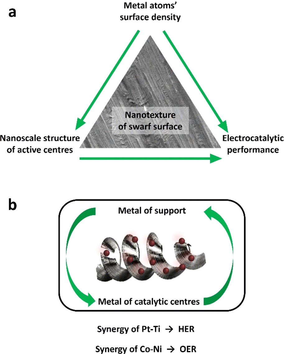 | ||
| Fig. 5 (a) A synergistic relationship between the metal of swarf and the metal of catalytic centres allows maximising electrocatalytic performance in the HER and OER. (b) The nanotextured surface of the swarf plays a critical role in stabilising catalytically active centres. The surface density of atomically deposited Pt or Co defines structures of catalytically active centres which translates to the functional performance of the electrocatalyst. | ||
We have shown that the morphology of catalytic centres at optimal metal loadings plays a crucial role in determining fundamental properties like electrochemical impedance and active surface area (Fig. 5b). Using SEM analysis, we have determined the mechanism of this effect: different atomic densities of Pt or Co on the surface of the swarf lead to drastically different structures of catalytically active centres, which translates to electrocatalytic performance of the swarf electrodes. Using overpotential values, we have demonstrated optimum surface densities for both Pt for the HER and Co for the OER. Consequently, maintaining strict control over metal loading at the optimal level is highly important for swarf electrodes. To ensure this precision, we employed a method of directly depositing Pt or Co atoms onto the swarf surface, with the atomic flux carefully defined in our experiments. This approach not only eliminated the need for solvents or reagents but also enhanced the quality of contact between the swarf support and electrocatalytic metal centres.21,22
Conclusions
A significant effort is currently being invested in the construction of nanostructured surfaces to enhance the catalytic, tribological and biological properties of materials. In this work, we successfully demonstrated that waste metal swarf possesses a remarkable nanotextured surface, that is naturally present and allows direct utilisation of discarded Ti and Ni metal waste as highly effective electrocatalyst support materials. The nanoscale grooves allow stabilisation of nanostructured Pt for the HER, and Co for the OER, resulting in low overpotentials and high electrochemically active surface areas required for H2 production from water. This allows the utilisation of electrocatalysts at very low mass loading, Pt (28 μg cm−2) and Co (30 μg cm−2) for the HER and OER, respectively. We have discovered that the size and morphology of the catalytic centres strongly influence electrocatalytic characteristics, which are controlled by the surface density of Pt and Co on the swarf. The nanotextured surface of the swarf provides an excellent microenvironment for HER and OER electrocatalysis opening a pathway for direct use of metal waste for hydrogen production and effective utilization of rare elements, such as platinum. This approach provides a powerful mechanism for tuning the performance of swarf-based electrodes. Indeed, we have successfully demonstrated a full-cell alkaline water electrolyser using electrodes based on a swarf. Our work paves the way to address two major challenges of modern industry – the recycling of waste metal and affordable hydrogen production – combined within a single process.Experimental
Preparation of stainless steel, nickel, and titanium alloy swarf
SST swarf was obtained by mechanically turning a 45 mm diameter rod of 304L stainless steel, employing a Tormach 15L Pro-Turn equipped with a 6 mm diameter TiCN-coated tungsten carbide button tool. A thorough preliminary testing phase was conducted to optimise parameters, resulting in the production of 6 mm wide spirals of swarf. The finalised parameters include a spindle speed of 600 rpm, a depth of 0.5 mm cut, and a feed rate of 0.06 mm per min. Swarf preparation was carried out without the use of a coolant, and the materials were collected in a clean container. Ti alloy (Ti–6Al–4V) swarf was obtained from industrially machined lathe swarf, generated under typical conditions that included the use of a coolant. The width of the Ti swarf matched that of the SST swarf at 6 mm. Inconel 625 and 718 were sourced from commercial industrial wastes. Before proceeding to the subsequent experimental stage, all swarf samples underwent ultrasonic cleaning in water, acetone and isopropanol. This rigorous cleaning process was implemented to remove any traces of coolant-based contamination. The elemental composition of the SST, Ti–6Al–4V, and Inconel 625 and 728 materials is shown in Table S1.†Atomic deposition of platinum and cobalt electrocatalysts
After ultrasonic cleaning, the electrodes were placed on a tailor-made sample holder (Fig. S14†) and exposed to a flow of atomically dispersed metal generated by magnetron sputtering in a vacuum, with the desired area of the swarf exposed by masking the rest using Kapton tape. Simultaneously, metals were also dispersed onto filter paper (Fig. S15†) to quantify the weight loading per unit area using ICP-OES analysis. An AJA magnetron sputtering system operated at a work-pressure of 3 mTorr (Ar gas), room temperature, 370 V and 16 mA was utilised to create a flow of metal atoms, with the deposition time varied as 45 s, 90 s and 180 s to control the weight loading of metal onto the electrodes.Characterisation
Scanning electron microscope (SEM) images of the samples were obtained using a JEOL 7100F Field Emission Gun microscope at a 10 kV e-beam, and elemental mapping was performed using an Oxford Instruments Aztec EDX system. The determination of the weight loading of sputter-deposited electrocatalysts was carried out using ICP-OES analysis. Briefly, the electrocatalyst-loaded filter paper was digested in 5 mL of aqua regia within a 15 mL centrifuge tube, using ultrasonication for 1 hour under a fume hood. Subsequently, it was allowed to stand undisturbed for 24 hours. Then, it was centrifuged twice to remove filter paper residues and diluted to a volume of 10 mL using a 5% HCl solution. The resulting clear liquid was used for ICP-OES analysis. X-ray photoelectron spectroscopy (XPS) was performed using a Kratos Liquid Phase Photoelectron Spectrometer instrument with a monochromatic Al Kα X-ray source (hν = 1486.6 eV) operated at room temperature with 10 mA emission current and 12 kV anode potential. The electron collection spot size was 400 μm. A pass energy of 160 eV was used for the survey scans and 20 eV for the high-resolution scans. Spectra were converted into VAMAS format for further analysis. The data was processed using CASA-XPS software. Charge correction was done in reference to C 1s at 284 eV.Electrochemical experiments
All electrochemical experiments were carried out using an Ivium CompactStat.h instrument in a standard three-electrode setup at room temperature. We employed the prepared Ti, SST, and Ni electrodes with a geometric surface area of 1 cm2 as the working electrodes. A platinum wire or graphite rod served as the counter electrode, and Hg/HgO was utilised as the reference electrode. The potentials observed against Hg/HgO were converted into the reversible hydrogen electrode (RHE) scale using the Nernst equation: E(RHE) = E(Hg/HgO) + 0.106 + 0.0596 × pH. Water reduction and oxidation onset potentials were determined using linear sweep voltammetry (LSV) in a 1 M KOH (5.6%) solution under an argon (Ar) atmosphere at a scan rate of 10 mV s−1. The resulting polarisation curve was subsequently used for Tafel analysis. For a deeper understanding of the electrode properties, the charge transfer resistance and double-layer capacitance were assessed using electrochemical impedance spectroscopy (EIS) at a constant bias of −1.3 V vs. Hg/HgO, covering a frequency range from 100 kHz to 1 Hz with a 10 mV amplitude. The electrochemically active surface area (ECSA) of the electrodes was calculated based on the double-layer capacitance at the electrode–electrolyte interface using eqn (1).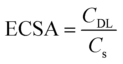 | (1) |
Full-cell alkaline water electrolysis
The most efficient HER and OER electrodes were selected for use as the cathode and anode in a full-cell electrolysis setup. The experiment was carried out within a conventional air-tight H-cell system (Ossila) with an anion exchange membrane (PiperION, FuelCell store) separating the cathodic and anodic compartments. An electrolyte of degassed 1 M KOH was used, and a voltage of +1.6 V vs. RHE was applied to the anode. The quantification of H2 and O2 evolution from the cathodic and anodic compartments was carried out at regular intervals using online gas chromatography (Agilent 8890, equipped with a thermal conductivity detector and Ar carrier gas). The faradaic efficiency of H2 and O2 evolution was determined using eqn (2).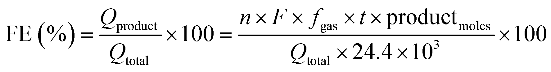 | (2) |
Author contributions
M. T, J. A. F. and A. N. K. developed the methodology. M. T. performed all electrochemical experiments and FEG-SEM imaging/EDX mapping. J. W. M., M. L., A. S. and A. T. C. prepared the swarf materials. E. C. K. performed XPS and sputtering of electrocatalysts. R. P. assisted in setting up the workbench. P. G. provided Inconel 625 alloys and actively participated in discussing results for scaling up the technology. M. T. performed all other characterisations and analyses, interpreted the data and wrote the manuscript. A. N. K., M. T. and J. A. F. supervised the work. All authors reviewed and edited the manuscript.Conflicts of interest
There are no conflicts to declare.Acknowledgements
The authors acknowledge the financial support from the Engineering and Physical Sciences Research Council (EPSRC), project Metal Atoms on Surfaces and Interfaces (MASI) for Sustainable Future (EP/V000055/1) and the University of Nottingham's Strategic Innovation Fund (SIF round 1 project). The authors thank the Nanoscale and Microscale Research Center (nmRC) for enabling access to SEM instrumentation, and Martin Roe for his assistance in SEM measurements.References
- A. Charpentier Poncelet, C. Helbig, P. Loubet, A. Beylot, S. Muller, J. Villeneuve, B. Laratte, A. Thorenz, A. Tuma and G. Sonnemann, Nat. Sustain., 2022, 5, 717–726 CrossRef.
- J. M. Allwood, C. F. Dunant, R. C. Lupton, C. J. Cleaver, A. C. H. Serrenho, J. M. C. Azevedo, P. M. Horton, C. Clare, H. Low, I. Horrocks, J. Murray, J. Lin, J. M. Cullen, M. Ward, M. Salamati, T. Felin, T. Ibell, W. Zho and W. Hawkins, Absolute Zero: Delivering the UK's Climate Change Commitment with Incremental Changes to Today's Technologies, 2019 Search PubMed.
- D. R. Cooper, Reuse of steel and aluminium without melting, University of Cambridge, 2014 Search PubMed.
- E. H. Kraft, Summary of emerging titanium cost reduction technologies, EHK Technologies, 2004 Search PubMed.
- P. Nyamekye, S. Rahimpour Golroudbary, H. Piili, P. Luukka and A. Kraslawski, Adv. Ind. Manuf. Eng., 2023, 6, 100112 Search PubMed.
- J. W. Murray, A. Speidel, A. Jackson-Crisp, P. H. Smith, H. Constantin and A. T. Clare, Int. J. Mach. Tools Manuf., 2021, 169, 103803 CrossRef.
- N. S. Weston and M. Jackson, Metals, 2020, 10, 296 CrossRef CAS.
- S. Dhiman, R. S. Joshi, S. Singh, S. S. Gill, H. Singh, R. Kumar and V. Kumar, J. Cleaner Prod., 2022, 348, 131342 CrossRef CAS.
- A. Ambrosi, J. G. S. Moo and M. Pumera, Adv. Funct. Mater., 2016, 26, 698–703 CrossRef CAS.
- I. Cano, A. Weilhard, C. Martin, J. Pinto, R. W. Lodge, A. R. Santos, G. A. Rance, E. H. Åhlgren, E. Jónsson, J. Yuan, Z. Y. Li, P. Licence, A. N. Khlobystov and J. Alves Fernandes, Nat. Commun., 2021, 12, 4965 CrossRef CAS PubMed.
- E. C. Kohlrausch, H. A. Centurion, R. W. Lodge, X. Luo, T. Slater, M. J. L. Santos, S. Ling, V. R. Mastelaro, M. J. Cliffe, R. V. Goncalves and J. Alves Fernandes, J. Mater. Chem. A, 2021, 9, 26676–26679 RSC.
- J. Pinto, A. Weilhard, L. T. Norman, R. W. Lodge, D. M. Rogers, A. Gual, I. Cano, A. N. Khlobystov, P. Licence and J. Alves Fernandes, Catal. Sci. Technol., 2023, 13, 4082–4091 RSC.
- J. Chen, M. Aliasgar, F. B. Zamudio, T. Zhang, Y. Zhao, X. Lian, L. Wen, H. Yang, W. Sun, S. M. Kozlov, W. Chen and L. Wang, Nat. Commun., 2023, 14, 1711 CrossRef CAS PubMed.
- F. Guo, T. J. Macdonald, A. J. Sobrido, L. Liu, J. Feng and G. He, Advanced Science, 2023, 10, 2301098 CrossRef CAS PubMed.
- A. R. Zeradjanin, A. Vimalanandan, G. Polymeros, A. A. Topalov, K. J. J. Mayrhofer and M. Rohwerder, Phys. Chem. Chem. Phys., 2017, 19, 17019–17027 RSC.
- C. A. C. Sequeira, D. M. F. Santos, E. Cameron and P. S. D. Brito, Mater. Technol., 2008, 23, 142–144 CrossRef CAS.
- E. Cossar, F. Murphy and E. A. Baranova, J. Chem. Technol. Biotechnol., 2022, 97, 1611–1624 CrossRef CAS.
- S. Kumaravel, R. Jayakumar, K. K. Saravanan, V. Niharika, B. Eunice Evangeline, V. Singaram and S. Kundu, Dalton Trans., 2022, 51, 17454–17465 RSC.
- M.-I. Jamesh and X. Sun, J. Power Sources, 2018, 400, 31–68 CrossRef CAS.
- I. Popov, S. Ghaderzadeh, E. C. Kohlrausch, L. T. Norman, T. J. A. Slater, G. N. Aliev, H. Alhabeadi, A. Kaplan, W. Theis, A. N. Khlobystov, J. A. Fernandes and E. Besley, Nano Lett., 2023, 23, 8006–8012 CrossRef CAS PubMed.
- J. Chen, Y. Zhang, Z. Zhang, D. Hou, F. Bai, Y. Han, C. Zhang, Y. Zhang and J. Hu, J. Mater. Chem. A, 2023, 11, 8540–8572 RSC.
- Z. Luo, G. Zhao, H. Pan and W. Sun, Adv. Energy Mater., 2022, 12, 2201395 CrossRef CAS.
- L. Francàs, S. Corby, S. Selim, D. Lee, C. A. Mesa, R. Godin, E. Pastor, I. E. L. Stephens, K.-S. Choi and J. R. Durrant, Nat. Commun., 2019, 10, 5208 CrossRef PubMed.
- S. Kumaravel, R. Jayakumar, K. K. Saravanan, V. Niharika, B. Eunice Evangeline, V. Singaram and S. Kundu, Dalton Trans., 2022, 51, 17454–17465 RSC.
- S. Trasatti and O. A. Petrii, J. Electroanal. Chem., 1992, 327, 353–376 CrossRef CAS.
- C. C. L. McCrory, S. Jung, J. C. Peters and T. F. Jaramillo, J. Am. Chem. Soc., 2013, 135, 16977–16987 CrossRef CAS PubMed.
- Q. Liu, J. Xu, Z. Chang and X. Zhang, J. Mater. Chem. A, 2014, 2, 6081–6085 RSC.
- H. Y. Kwong and Y. W. Wong, J. Alloys Compd., 2010, 497, 267–271 CrossRef CAS.
- L. Francàs, S. Corby, S. Selim, D. Lee, C. A. Mesa, R. Godin, E. Pastor, I. E. L. Stephens, K.-S. Choi and J. R. Durrant, Nat. Commun., 2019, 10, 5208 CrossRef PubMed.
- S. Zhang, S. Zhang, W. Leng and D. Wu, J. Alloys Compd., 2022, 927, 166975 CrossRef CAS.
Footnote |
| † Electronic supplementary information (ESI) available. See DOI: https://doi.org/10.1039/d4ta00711e |
| This journal is © The Royal Society of Chemistry 2024 |