
 Open Access Article
 This Open Access Article is licensed under a
 Creative Commons Attribution 3.0 Unported Licence
Active sites-enriched hierarchical MoS2 nanotubes: highly active and stable architecture for boosting hydrogen evolution and lithium storage†
Jin
Wang‡
ab,
Jilei
Liu‡
bc,
Hao
Yang
*d,
Zhen
Chen
ab,
Jianyi
Lin
*c and
Ze Xiang
Shen
*ab
aEnergy Research Institute (ERI@N), Interdisciplinary Graduate School, Nanyang Technological University, Research Techno Plaza, 50 Nanyang Drive, 637553, Singapore
bDivision of Physics and Applied Physics, School of Physical and Mathematical Sciences, Nanyang Technological University, 21 Nanyang Link, 637371, Singapore. E-mail: Zexiang@ntu.edu.sg
cEnergy Research Institute (ERI@N), Nanyang Technological University, 50 Nanyang Drive, 637553, Singapore. E-mail: LIJY@ntu.edu.sg
dJiangsu Key Laboratory of Advanced Laser Materials and Devices, School of Physics and Electronic Engineering, Jiangsu Normal University, Xuzhou 221116, China. E-mail: yanghao@jsnu.edu.cn
First published on 18th April 2016
Abstract
The design of nanostructures with sufficient active sites is considerably challenging but highly desirable for energy applications. Herein, highly active tubular MoS2 structures on flexible three-dimensional graphene foam are firstly produced by a bottom-up approach using Ni3S2 nanowires as the precursor and self-sacrificial template. The hierarchical tubular structures with high surface curvature expose a large fraction of edge sites and defects, which, along with high surface area, lead to excellent activity for electrocatalytic hydrogen evolution. Remarkably, the integrated hydrogen-evolving electrode operating in acidic electrolytes exhibits high stability and excellent electrocatalytic activity with a low onset overpotential of 77 mV, Tafel slope of 52 mV per decade and large exchange current density of 6.4 × 10⁻² mA cm−2. When evaluated as an anode material for LIBs, these hierarchical MoS2 nanotubes manifest high specific capacity and excellent rate capability as well as extremely long-term cycle stability. This work elucidates how structure design of nanomaterials can significantly impact the surface structure at the atomic scale, enabling new opportunities for enhancing structure properties and other important technological applications.
Introduction
Since the discovery of carbon nanotubes in 1991, intensive efforts have been motivated to fabricate various types of nanotubes due to their unique physical/chemical properties and expansive applications in a variety of fields.1–3 Similar to carbon, fullerene-like and tubular transition-metal dichalcogenides (TMDs) have been increasingly investigated both theoretically and experimentally.4–9 MoS2, as a typical layered metal dichalcogenide, has been widely recognized as a universal material for energy applications. Novel applications of tubular structured MoS2 in catalysis, energy storage, lubricants, electronics and optoelectronics have driven the development of synthesis strategies that enable control of its structure and morphology.10–28 MoS2 nanotubes were firstly synthesized by Tenne et al. by a gas reaction of MoO3 and H2S under a reducing atmosphere at elevated temperatures (800–950 °C).7,29 Chen and co-workers also reported the synthesis of open-ended MoS2 nanotubes by a gas-solid reaction.11 However, these approaches for the fabrication of MoS2 nanotubes always require complicated procedures with high temperatures or dangerous gases (H2 and H2S). Besides, extensive research has proved that hollow nanotubes with abundant active edge sites and high specific surface area can achieve excellent performance in many applications.30–33 Recently, a variety of solution-phase strategies have also been adopted to synthesize tubular MoS2 structures with high surface area. For example, Zhang et al. reported an anion-exchange method for the synthesis of hierarchical tubular MoS2 structures, which exhibit high activity and stability for photoelectrocatalytic and electrocatalytic hydrogen-evolution reaction (HER).30 Wang et al. synthesized 3D assembled tubes constructed by single-layered MoS2 nanosheets through a solvothermal method.31 The assembled tubular architecture exhibits excellent electrochemical performance as an anode material of lithium-ion batteries (LIBs), and high activity in HDS catalysis. The excellent properties are probably attributed to the porous tubular architecture, which can shorten the transport path of lithium ions, and provide sufficient exposed active sites for reactions. These important results represent that it is a significant topic to tune the properties of MoS2 nanotubes by controlling their microstructures. Despite these advances in the fabrication of tubular nanostructures, it is still a considerable challenge to obtain MoS2 nanotubes with sufficient exposed active sites, high specific surface area and robust stability by a facile method.Herein, we develop a facile template-assisted approach for the construction of hierarchical MoS2 hollow nanotubes implanted with exceptional active sites. The synthesized hierarchical nanotubes are constructed byMoS2 hollow nanotubes decorated with MoS2 nanosheets, which are self-supported on flexible three-dimensional graphene foam (3DGF). We denote it as MT@MS/GF. The obtained hierarchical MT@MS/GF exhibits excellent electrocatalytic activity and high stability with low overpotential in an acidic electrolyte for the electrochemical HER. In addition, when evaluated as an anode material for LIBs, the binder-free hierarchical MoS2 electrode manifests high specific capacity and excellent rate capability as well as extremely long-term cycle stability.
Experimental section
Synthesis of elongated core/shell Ni3S2@MoS2 coaxial nanofibers on Ni/graphene foam
The growth of Ni/graphene foam (Ni/GF) was achieved by our reported method.23 MoS2/Ni3S2@MoS2 nanofibers were prepared using a facile one-step hydrothermal process.34 In a typical experiment, a mixed solution was prepared by dissolving 150 mg of thiourea (NH2CSNH2), 75 mg of sodium molybdate (Na2MoO4) and 0.2 g of polyvinylpyrrolidone (PVP) in 30 mL of distilled water. Then, the resulting solution was transferred into a Teflon-lined stainless steel autoclave. A piece of Ni/GF with an area of 8 cm2 was immersed into the reaction solution. The autoclave was then sealed and the hydrothermal reaction was conducted at 200 °C for 12 h. After the autoclave was cooled down to room temperature, the samples were rinsed with DI water for several times and then dried in an electric oven at 60 °C for 12 h. The achieved samples were thermally decomposed in a tube furnace at 400 °C for 2 h under a H2/Ar (5![[thin space (1/6-em)]](https://www.rsc.org/images/entities/char_2009.gif) :95 v/v) atmosphere with a heating rate of 10 °C min−1. For comparison, the samples were prepared with the same reactant concentration at 200 °C for 8 h to prepare Ni3S2@MoS2 nanofibers on graphene foam.
:95 v/v) atmosphere with a heating rate of 10 °C min−1. For comparison, the samples were prepared with the same reactant concentration at 200 °C for 8 h to prepare Ni3S2@MoS2 nanofibers on graphene foam.
Synthesis of hierarchical MoS2 nanotubes on graphene foam
The obtained Ni3S2–MoS2 hybrid nanofibers supported on Ni/GF were immersed in a mixed solution of FeCl3 (1 M) and HCl (0.5 M) for 48 h. Meanwhile, Ni3S2 was oxidized to NiS2. In order to remove the residual NiS2, the obtained samples were hydrothermally treated in 5 M HCl solution at 90 °C for 4 h, followed by washing with DI water until neutral pH, and drying at 60 °C in an electric oven. Thus hierarchical MoS2 nanotubes directly supported on 3DGF were obtained. After hydrothermal treatment, MoS2/Ni3S2@MoS2 nanofibers supported on Ni/GF transformed into MoS2 hollow nanotubes decorated with MoS2 nanosheets on 3DGF, which is denoted as MT@MS/GF. Meanwhile, Ni3S2@MoS2 nanofibers supported on Ni/GF transformed into tubular MoS2 nanostructures on 3DGF, which is denoted as MT/G. The weight of MoS2 in the 3D architectures is calculated by weighting 3DGF and the final hierarchical composites after hydrothermal treatment.Characterization
The X-ray powder diffraction (XRD) pattern of each sample was recorded on a Bruker D8 Advance powder X-ray diffractometer using Cu Kα radiation (λ = 0.15406 nm). Field emission scanning electron microscopy (FESEM, model JSM-7600F, JEOL Ltd, Tokyo, Japan) was used to characterize the morphologies of the synthesized samples. Transmission electron microscopy (TEM) images were taken using a JOEL JEM 2100F microscope. Raman spectroscopy was recorded using a Renishaw Raman microscope with a 2.33 eV (532 nm) excitation laser. The Si peak at 520 cm−1 was used as the reference to calibrate the wave number. The XPS measurements were performed with a VG ESCALAB 220i–XL system using a monochromatic Al Kα1 source (1486.6 eV). All XPS spectra were obtained in the constant pass energy (CPA) mode. The pass energy of the analyser was set to 10 eV to have high measurement accuracy. The binding energy scale was calibrated with pure Au, Ag and Cu by setting Au 4f7/2, Ag 3d5/2 and Cu 2p3/2 at binding energies of 84.0, 368.3 and 932.7 eV, respectively. Surface area analysis was conducted using the Brunauer–Emmett–Teller (BET) theory (Micromeritics, ASAP 2020).Cell assembly and electrochemical measurements
To test the anode performance of all synthesised materials, CR 2016 coin cells were made using a Celgard 2400 as the separator and 1 M LiPF6 in ethylene carbonate–diethylene carbonate (EC:DEC = 1:1) as the electrolyte. Li-metal was used as the counter and reference electrodes. The coin cells were assembled inside an argon-filled glovebox with oxygen and water contents below 1 and 0.1 ppm, respectively. The obtained MT@MS/GF and MT/GF were punched to a disk-shaped electrode with a diameter of 12 mm for the electrochemical measurements, which were directly used as working electrodes and assembled into coil cells without adding any conductive or binding materials. Galvanostatic charging and discharging tests were conducted using a battery tester (NEWARE) at different current rates. It should be noted that all the specific capacities reported in this work are based on the total mass of the composites rather than the mass of MoS2 only. Cyclic voltammetry (CV) was performed using an electrochemical workstation (CHI 760D, Chenhua, Shanghai) from 10 mV to 3 V at a scanning rate of 0.5 mV s−1. Electrochemical impedance spectroscopy (EIS) was also carried out with an electrochemical workstation over a frequency range from 106 Hz to 100 mHz at open circuit potential after two galvanostatic charging and discharging cycles at 100 mA g−1.
Electrocatalytic study
The obtained MT@MS/GF and MT/GF composites with an area of 1 cm2 were directly used as working electrodes for HER performance evaluation. The electrochemical HER tests were performed in a 0.5 M H2SO4 electrolyte with platinum foil and saturated calomel electrode (SCE) as counter and reference electrodes, respectively, within a three electrode set-up. The potentials reported in our work were vs. the reversible hydrogen electrode (RHE) through RHE calibration described below. Linear sweep voltammetry was conducted in 0.5 M H2SO4 with a scan rate of 5 mV s−1. The polarization curves were replotted as overpotential (η) vs. log current (logj) to obtain Tafel plots for assessing the HER kinetics of the investigated catalysts. By fitting the linear portion of the Tafel plots to the Tafel equation (η = blog(j) + a), the Tafel slope (b) can be obtained. All data were reported without iR compensation. In all measurements, we used SCE as the reference electrode. It was calibrated with respect to RHE. The calibration was performed in the high-purity hydrogen-saturated electrolyte with a Pt foil as the working electrode. Cyclic voltammetry was run at a scan rate of 5 mV s−1, and the average of the two potentials at which the current crossed 0 was taken to be the thermodynamic potential for the hydrogen electrode reaction. In 0.5 M H2SO4 solution, ERHE = ESCE + 0.28 V. The long-term stability tests were performed by continuous linear sweep voltammetry (LSV) scans from 0.08 to 0.88 V (vs. RHE, in 0.5 M H2SO4) at a sweep rate of 5 mV s−1.
Results and discussion
The synthesis strategy of hierarchical MT@MS/GF is schematically depicted in Fig. 1. First, few-layer MoS2 nanosheets decorated Ni3S2@MoS2 coaxial nanofibers on 3DGF/Ni are employed as the template, which are synthesized through a facile hydrothermal method.34 Scanning electron microscopy (SEM) and transmission electron microscopy (TEM) images show the as-synthesized sample with an obvious core–shell structure, in which a large amount of ultra-small few-layer MoS2 nanosheets decorate elongated Ni3S2@MoS2 coaxial nanofibers (denoted as MoS2/Ni3S2@MoS2) (Fig. S1a–d†). It should be noted that MoS2/Ni3S2@MoS2 nanofibers are self-supported on 3DGF/Ni. The as-prepared hierarchical MoS2/Ni3S2@MoS2 nanofibers are transformed into hierarchical MoS2 tubular architectures by selectively removing the Ni3S2 sacrificial template after a FeCl3-assisted etching process, while MoS2 is chemically stable during the etching process. Meanwhile, the nickel substrate from 3DGF/Ni can be effectively etched. Then, we can obtain hierarchical MoS2 tubular architectures directly supported on 3DGF. The detailed reaction equations are described as follows.35| Ni3S2 + 4FeCl3 → NiS2+ 4FeCl2 + 2NiCl2 | (1) |
| NiS2 + 2HCl → NiCl2 + H2S | (2) |
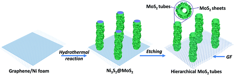 | ||
| Fig. 1 Illustration of the synthesis process of hierarchical MT@MS/GF. | ||
Detailed procedures are given in the Experimental section. The phase and morphology of the as-prepared sample were systematically investigated by XRD and SEM. The XRD pattern of the obtained sample can be assigned to the hexagonal phase MoS2 (a = b = 0.316 nm, c = 1.230 nm, JCPDS card no. 37–1492) and GF (Fig. 2a). The GF displays a typical diffraction peak at 26.5° corresponding to the (002) reflection of graphitic carbon (JCPDS card no. 75–1621). The highly crystalline structure of GF is further characterized in Fig. S2.† The SEM image reveals its tubular morphology with uniform diameters of 50–100 nm and lengths of above 2 μm (Fig. 2b). The MT@MS/GF composites were sonicated in ethanol for 10 min. The hierarchical tubular structures collapsed due to the ultrasonication effect, which were then dropped onto a TEM grid and dried under ambient conditions. The TEM image shows uniform nanotubes with inner and outer diameters of 30 and 50 nm (Fig. 2c). Close examination clearly indicates that a typical nanotube is composed of MoS2 layers (5–8 layers) with an interlayer spacing of 0.68 nm, which are further decorated with a large amount of ultra-small MoS2 nanosheets (Fig. 2d and e). Partial nanotube walls show obvious broken layers with rich defects, highlighted by the dashed lines in Fig. 2d, which are probably caused by the detachment of Ni3S2 nanofibers during the etching treatment. Further, the HRTEM image shows the atomic structures of the nanotube (Fig. 2e). The (001) planes are parallel to each other and together constitute the tubular structure with an interlayer distance of 0.68 nm. The enlarged HRTEM image shows the regular hexagonal lattice orientation of 2H-MoS2 (Fig. 2f). The fast Fourier transformation (FFT) pattern in the inset reveals the orientation along the [001] zone axis. High-angle annular dark-field scanning transmission electron microscopy (HAADF-STEM) images clearly confirm the hollow tube-like morphologies and uniform composition distribution of the obtained nanotubes (Fig. 2g–i). The energy dispersive X-ray spectrometry (EDS) results also confirm the composition of MoS2 (Fig. 2j).
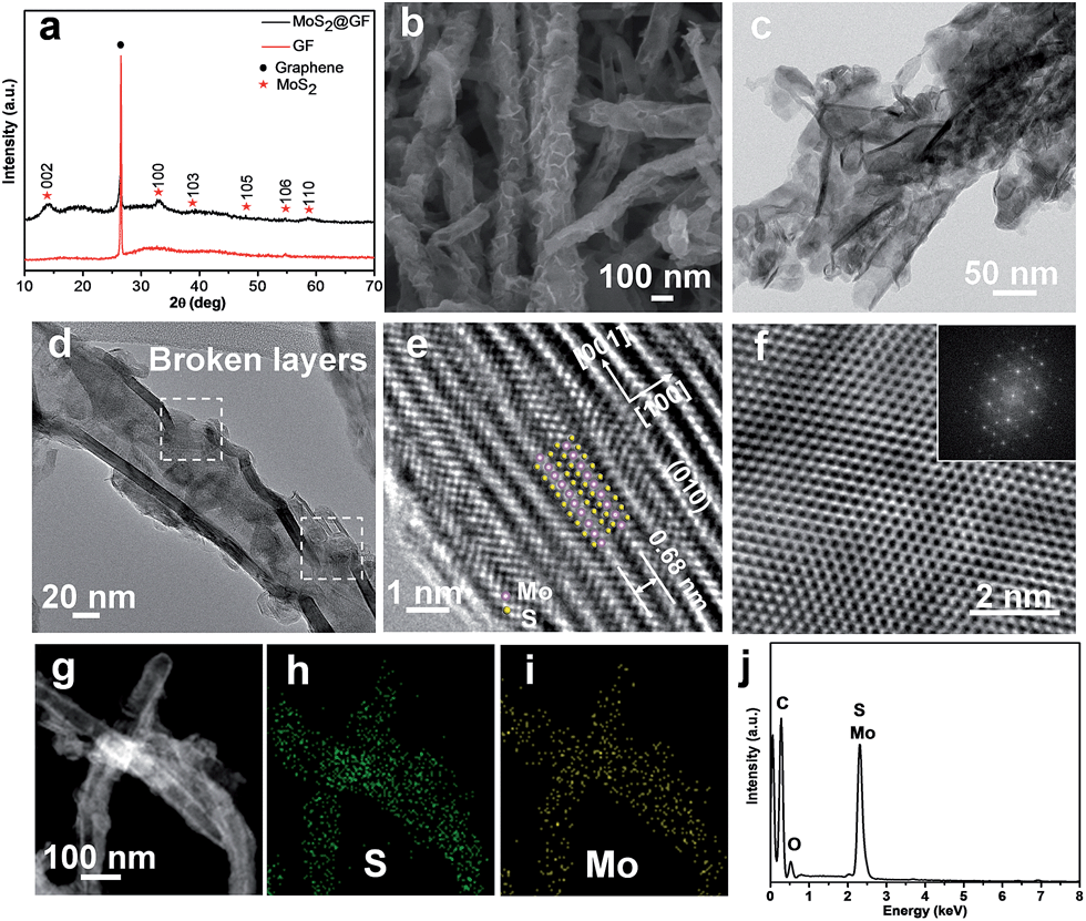 | ||
| Fig. 2 (a) XRD pattern and (b) SEM image of MT@MS/GF. (c) TEM image of MT@MS showing a similar structure to (a). (d) HRTEM images of MT@MS, showing broken surface layers and crystal planes of MT@MS. (e) HRTEM images of MoS2 walls in MT@MS. The image plane is the (010) plane stacking with the interlayer distance of 0.68 nm. (f) HRTEM images of a MoS2 sheet in MT@MS showing the view parallel to the c axis of MoS2 nanocrystals. Inset (f): the corresponding selected area electron diffraction (SAED) image. (g) HAADF-STEM image, corresponding EDS maps of MT@MS for S (h), Mo (i), and the EDS spectrum (j). | ||
Raman spectroscopy was used to further investigate the structures of the MT@MS/GF and bare GF. Two obvious peaks at 1580 and 2720 cm−1 are attributed to the G and 2D bands of GF, respectively (Fig. 3a). The high 2D/G intensity ratio as well as the absence of the D band at 1350 cm−1 in the GF spectrum demonstrates the high quality of GF before MoS2 growth. By contrast, the appearance of the D band at 1350 cm−1 after MoS2 growth indicates the presence of sp3 bonding which successively corroborates a strong coupling between MoS2 and GF. Two characteristic peaks at 380 and 405 cm−1 in the MT@MS/GF sample are attributed to E12g and A1g modes of MoS2, respectively. X-ray photoelectron spectroscopy (XPS) was employed to further probe the chemical states of S and Mo in MT@MS/GF (Fig. 3b and c). Two peaks of Mo 3d3/2 and Mo 3d5/2 at binding energies of 232.5 and 229.3 eV correspond to the characteristic peaks of Mo4+ in MoS2. The S 2p peaks at 162 and 163.2 eV are ascribed to the characteristic peaks of S2− in MoS2.36,37 In virtue of the hollow tubular structure and ultrathin nanosheets, the MT@MS/GF sample with the hierarchical hollow structure exhibits a high Brunauer–Emmett–Teller (BET) surface area of 89.6 m2 g−1 with abundant mesoporous channels (Fig. 3d).
 | ||
| Fig. 3 Detailed microstructure characterization. (a) Raman spectra of MT@MS/GF. XPS spectra of (b) S 2p peaks and (c) Mo 3d peaks of MT@MS/GF. (d) N2 adsorption/desorption isotherms; inset: corresponding pore size distribution of MT@MS/GF. | ||
The morphology of hierarchical MoS2 hollow nanotubes on 3DGF can be optimized using the template precursor. This enables us to study the correlation between the microstructure and electrochemical performance. Herein, for comparison, we also fabricate MoS2 hollow nanotubes on 3DGF, but without the decorating MoS2 nanosheets (denoted as MT/GF), which are derived from core–shell Ni3S2–MoS2 nanofibers with a homogeneous heterointerface on 3DGF/Ni (denoted as Ni3S2@MoS2) (Fig. S1d–f†). The TEM image of MT/GF shows that the typical nanotubes are composed of MoS2 layers with a wall thickness of 5–10 nm (Fig. 4a and b). The enlarged HRTEM image clearly indicates that a typical hollow nanotube is indeed composed of MoS2 layers (∼10 layers) with an interlayer spacing of 0.68 nm (Fig. 4c). Further examination shows the regular hexagonal lattice orientation of 2H-MoS2 (Fig. 4d). The fast Fourier transformation (FFT) pattern in the inset reveals the orientation along the [001] zone axis. The XRD pattern also confirms the pure phase of MT/GF (Fig. S3†).
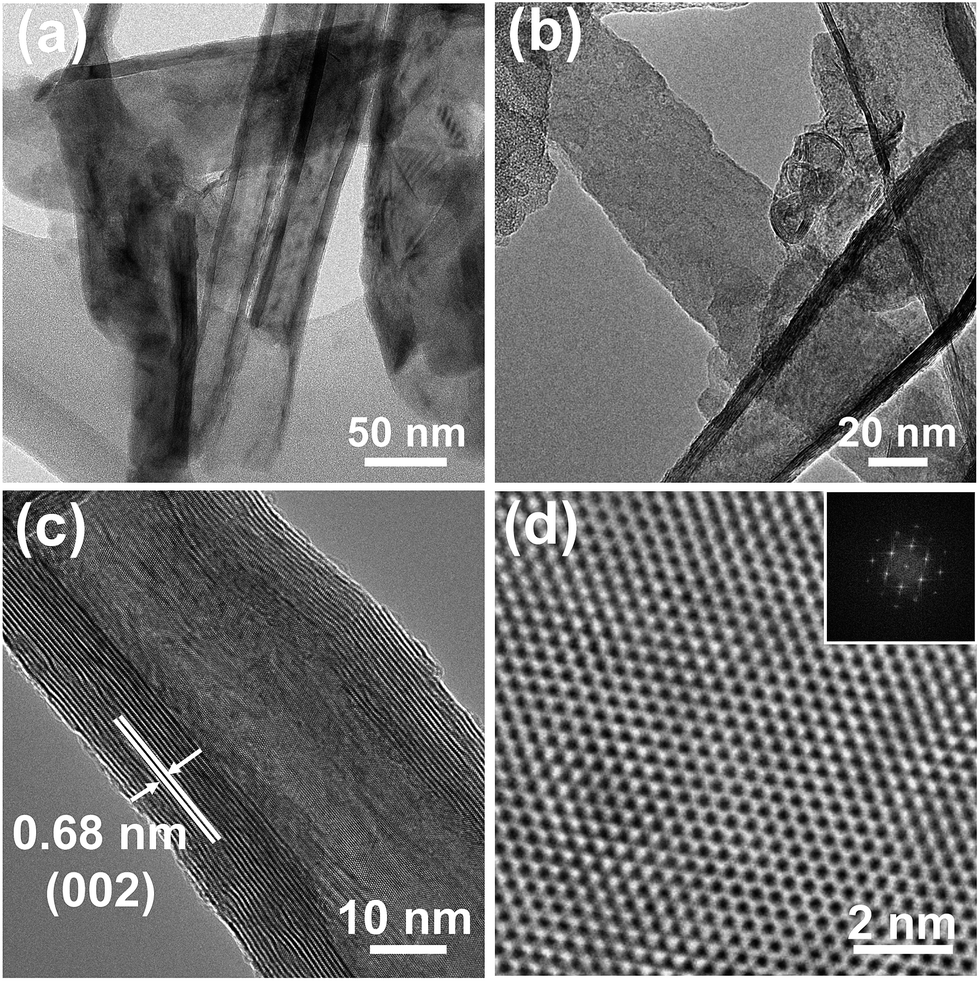 | ||
| Fig. 4 (a) and (b) TEM images of MT/GF. (c) HRTEM images of tubular MoS2, showing regular crystal planes of MoS2. (d) HRTEM images of tubular MoS2, showing the view parallel to the c axis of MoS2 nanocrystals. Inset (d): the corresponding selected area electron diffraction (SAED) image. | ||
Recently, MoS2 and its composites demonstrated their intriguing performance for lithium storage and remarkable efficiency as catalysts of HER.32,33,38–54 The decent lithium storage and HER properties have been demonstrated (see a complete list in Tables S1 and S2†). In this study, we investigate the electrocatalytic HER activities of MT@MS/GF in comparison with MT/GF. A three-electrode setup is employed to evaluate the electrocatalytic HER activities in 0.5 M H2SO4 electrolyte. Note that the test is operated in a static state (without rotation) to simulate the real industrial operation. The bare GF shows negligible background activity for H2 evolution (Fig. 5a), which is similar to other reports.39,55,56 A reductive sweep of the MT@MS/GF sample shows a low overpotential (η) of 77 mV for HER, beyond which a sharp increase in the cathodic current starts to appear, attributed to electrocatalytic H2 evolution (Fig. 5a). By contrast, the MT/GF catalyst exhibits inferior HER activity with lower catalytic current and larger onset overpotential of 161 mV.
 | ||
| Fig. 5 Electrocatalytic hydrogen evolution performance of various catalysts. (a) Polarization curves of MT@MS/GF, MT/GF and GF at a scan rate of 5 mV s−1. (b) Tafel plots of the various catalysts derived from (a). (c) Durability test indicating negligible current loss even after 3000 CV cycles. (d) Time dependence of current density under a constant potential of −0.17 V vs. RHE. | ||
In order to prove the presence of increased active sites provided by the hierarchical MT@MS/GF, the number of active sites for MT@MS/GF and MT@GF was estimated based on the voltammetry method (Fig. S4†).21,57,58 The related calculation method is presented in the ESI.† As shown in Table 1, the MT@MS/GF catalyst exhibits a density of active sites of 1.878 × 10⁻³ mol g−1, which is obviously higher than that of the MT@GF catalyst (0.965 × 10⁻³ mol g−1). The larger number of active sites implanted in MT@MS/GF can be attributed to its hierarchical nanotubes with massive defects and the inherent reactive surfaces of nanotubes due to their curvature. It has been proved that MoS2 morphology with a radius of curvature of nanoscale dimensions is expected to engender more exposed edge sites by imposing geometric constraints that can markedly change the thermodynamic stabilities of different surface features.59 Another possible cause is that the hierarchical tubular structure possesses high surface area and diverse mesoporous channels, which are favourable for the fast ion diffusion and close electrode-electrolyte contact, leading to the enhanced electrocatalytic activity. The turnover frequency (TOF) for each active site of the MT@MS/GF catalyst was calculated to be 0.957 s−1 at η = 300 mV, which is much higher than the TOF value of the MT@GF catalyst, indicating its better intrinsic catalytic activity. The HER kinetics of the various catalysts mentioned above was investigated through the corresponding Tafel plots (logj–η) (Fig. 5b). The linear portions in the Tafel plots were fitted according to the Tafel equation (η = blog|j| + a) and the Tafel slope (b) was obtained. A Tafel slope of 52 mV per decade was obtained for the MT@MS/GF sample (Fig. 5b), which is far lower than that of 94 mV per decade for the MT/GF sample (Table 1), testifying the superior HER kinetics of the MT@MS/GF sample. At high current densities, the MT@MS/GF sample also acts as a more efficient catalyst than MT/GF. The inherent HER activities of these catalysts were estimated with the exchange current density (j0). The MT@MS/GF sample exhibits a j0 of 6.4 × 10⁻² mA cm−2, outperforming the value of 2.5 × 10⁻² mA cm−2 for the MT/GF sample. The outstanding kinetic metrics (low onset overpotential of 77 mV and Tafel slope of 52 mV per decade) and large j0 (6.4 × 10⁻² mA cm−2) highlight the extraordinary hydrogen evolution efficiency of this novel structured MT@MS/GF catalyst. Stability is another significant criterion to evaluate the catalysts. The negligible difference in the J–V curves before and after 3000 CV cycles demonstrates the superior stability of the MT@MS/GF sample in a long-term electrochemical reaction (Fig. 5c). To probe the durability of the MT@MS/GF sample in an acidic environment, continuous HER measurement at a static overpotential and long-term cycling test was conducted. The curve of time dependence of current density shows a typical serrate shape under a constant potential of −0.17 V vs. RHE (Fig. 5d), which is probably related to the alternative processes of bubble accumulation and release. For the hierarchical MT@MS/GF sample, the current density decreases gradually in the initial 0.5 h, and then increases slightly over 4 h of continuous operation. It is hypothesized that the activation process during the initial 0.5 h can allow more electrolyte to access the MT@MS/GF interfaces by capillary penetration due to the hierarchical structure, leading to the increased HER current density. Besides, XPS and Raman studies of the sample after 4 h of operation revealed no obvious chemical state change of HER-active Mo (Fig. S5†). In comparison, under the same measurement conditions, the MT/GF catalyst exhibited a slow but progressive decrease in HER activity (Fig. S6†). The extraordinary long-term durability of the tubular MT@MS/GF catalyst suggests its promise as a realistic hydrogen evolution electrode. Meanwhile, the hierarchical tubular structures of the MT@MS/GF electrode are still detectable even after long-term HER cycling, indicating the good stability of its hierarchical tubular structure (Fig. S7†).
| Catalyst | Number of active sites [10−3 mol g−1] | TOF [s−1] | Tafel slope [mV per decade] | Onset overpotential [mV vs. RHE] | Exchange current densities (j0) [mA cm−2] |
|---|---|---|---|---|---|
| MT@MS/GF | 1.878 | 0.957 | 52 | 77 | 6.4 × 10⁻² |
| MT/GF | 0.965 | 0.496 | 94 | 161 | 2.5 × 10⁻² |
The experimentally measured high catalytic HER activities (j0 = 6.4 × 10⁻² mA cm−2) of the MT@MS/GF catalyst prompted us to investigate the mechanism responsible for the enhanced activity. Previous density functional theory (DFT) calculations indicated that the MoS2 basal plane was inactive while only edge sites of nanoscale particles with coordinated unsaturated Mo atoms were active for HER, which was later proved by Jaramillo et al. experimentally.60,61 Xie et al. found that rich defects resulted in partial cracking of the catalytically inert basal planes, leading to the exposure of additional active edge sites.40 Herein, our MT@MS/GF sample with high specific surface area and diverse mesopores possesses cracked MoS2 nanotubes with broken layers and massive defects can extend massive exposed active edge sites, leading to the enhancement of the HER activity. Also, a mass of ultra-small few-layered MoS2 sheets covers the entire surfaces of nanotubes, which provides accessible catalytic centres for HER. Furthermore, the entire surfaces of nanotubes are regarded to be reactive due to the curvature and a distortion of the bond angles, leading to a preferentially maximum exposure of the catalytically active sites. Meanwhile, the graphene scaffolds may also boost the HER-activity of MT@MS due to the increased electrical conductivity, leading to fast electron transfer and high electrocatalytic efficiency towards HER.
For HER in acidic media, two separate pathways (the Volmer–Tafel and the Volmer–Heyrovsky mechanism) have been proposed for reducing H+ to H2. The Volmer–Heyrovsky mechanism involves two principal steps, referred to as the Volmer [eqn (3)] and Heyrovsky [eqn (4)] steps, while the Volmer–Tafel mechanism proceeds via the combination of Volmer [eqn (3)] and Tafel [eqn (5)] reactions.62,63
| H3O+ + e− → Hads + H2O | (3) |
| Hads + H3O+ + e− → H2 + H2O | (4) |
| Hads + Hads → H2 | (5) |
The Tafel slope, an intrinsic property of electrocatalysts, could be used to probe the rate-determining step and elementary steps involved in the H2 evolution. In a recent study, under a specific set of conditions, it has been reported that a Tafel slope of about 120, 40 or 30 mV per decade will be obtained if the Volmer, Heyrovsky or Tafel reaction is the rate-determining step, respectively.63 Ideally, the Tafel slope is an inherent property of electrocatalytic materials, which is a useful indicator of the rate-limiting step for reactions involving electron transfer. In reality, however, the Tafel slope can be dependent on many factors other than the kinetic exponent of the electrons, such as the coverage of adsorbates and the mass transport effect in porous structures.64 Since our Tafel slope was determined in the high coverage region, the value of 52 mV may imply a Heyrovsky rate-deterring step. Due to the complexity of the reaction mechanism, analyzing the Tafel slope is still inconclusive for identifying the HER of MoS2. However, the Tafel slope of 52 mV per decade obtained in this work is comparable to the value of 36–68 mV per decade of bulk Pt (shape-dependent) in 0.5 M H2SO4 and close to that of defect-rich MoS2 ultrathin nanosheets reported previously, which suggests a similar surface chemistry of our hierarchical MT@MS/GF.40
In this study, we also investigate the electrochemical properties of MT@MS/GF as an anode material for LIBs. The CV curves of MS@MT/GF in the first four cycles are presented in Fig. 6a, which are similar to those reported.65,66 The shape of the CV curve and the oxidation/reduction peaks are still retained in the cycles, indicating the good stability of the anode. The hierarchical MS@MT/GF delivers initial discharge and charge capacities of 1487 and 1215 mA h g−1, respectively, giving a coulombic efficiency of 81.7% (Fig. 6b). The coulombic efficiency rapidly reaches more than 99% after the second cycle. The second and third discharge profiles almost coincide with each other, proving the excellent cycling performance. The hierarchical MS@MT/GF exhibits excellent rate performance. At high current densities of 1 and 2 A g−1, specific capacities of 1025 and 916 mA h g−1 can be maintained, respectively (Fig. 6c). Even when cycled at a high current density of 5 A g−1, a specific capacity of 878 mA h g−1 can be maintained. Remarkably, these values are much higher than that of MT/GF (731 mA h g−1). The cycling performance is also outstanding: even after 200 cycles, both discharge and charge capacities of the hierarchical MS@MT/GF can remain at 892 mA h g−1 at a current density of 500 mA g−1, delivering nearly 76.5% of capacity retention (Fig. 6d). In contrast, the MT/GF electrode shows lower capacities and much faster capacity fading under the same testing conditions, and a capacity of only ∼727.4 mA h g−1 is retained after 100 cycles (Fig. S8†). A complete comparison of the electrochemical properties of these two samples, summarized in Table S3,† shows that MS@MT/GF possesses excellent electrochemical properties, including high initial coulombic efficiency, high specific capacity, excellent rate performance and stable cyclability. The remarkable lithium storage properties of the hierarchical MT@MS/GF catalyst are probably related to its unique tubular architecture constructed by MoS2 nanosheets-decorated nanotubes. Especially, the hierarchical tubular structure possesses high surface area and massive mesopores, which are favorable for a short diffusion distance of lithium ions and a large electrode–electrolyte contact area, leading to the enhanced rate capability. Meanwhile, the decorating ultrathin 2D nanosheets and the inner void space in the hollow tubular structure not only allow fast lithium ion diffusion, but also effectively buffer the mechanical stress caused by volume variation during the lithium intercalation/exfoliation, thus leading to the enhanced cycling stability. The hierarchical tubular structures in the MT@MS/GF electrode are still sustained with little structural deformation even after long-term cycling, indicating their good stability (Fig. S9†).
 | ||
| Fig. 6 (a) The first 4 cycles CV curves of MT@MS/GF at a scan rate of 0.2 mV s−1, (b) the first three charge and discharge curves of MT@MS/GF at a current density of 100 mA g−1, (c) cycling behavior of the MT@MS/GF and MT/GF electrodes at various current densities, (d) cycling behaviors of the MT@MS/GF electrode at a current density of 500 mA g−1. | ||
Conclusions
In summary, we have developed a facile method to prepare robust MoS2 hollow nanotubes implanted with high density of active sites that exhibit excellent catalytic activity for HER. The obtained hierarchical nanotubes are constructed by MoS2 hollow nanotubes decorated with MoS2 nanosheets, which are self-supported on flexible 3DGF. The hierarchical hollow nanotubes show enhanced lithium storage and excellent electrocatalytic activity towards HER with quite good stability, arising from preferentially exposed more catalytically active edge sites. In particular, the hierarchical tubular structure possesses high surface area and diverse mesoporous channels, which are favorable for fast ion diffusion and close electrode–electrolyte contact, leading to the enhanced electrocatalytic activity and lithium storage. All these merits undoubtedly contribute to the enhancement of electrochemical properties, including a low onset overpotential of 77 mV, Tafel slope of 52 mV per decade and large exchange current density of 6.4 × 10⁻² mA cm−2. In addition, when evaluated as an anode material for LIBs, these hierarchical MoS2 nanotubes manifest high specific capacity and excellent rate capability as well as extremely long-term cycle stability. This method can be used for the preparation of other tubular structures for future clean energy applications.Acknowledgements
The authors acknowledge support from the Energy ResearchInstitute@NTU (ERI@N). We also acknowledge the financial support from the Ministry of Education, Tier 1 (Grant no: M4011424.110) and Tier 2 (Grant no: M4020284.110). H. Yang acknowledges a project funded by the Priority Academic Program Development of Jiangsu Higher Education Institutions (PAPD).References
- S. Iijima, Nature, 1991, 354, 56–58 CrossRef CAS.
- R. Tenne, L. Margulis, M. Genut and G. Hodes, Nature, 1992, 360, 444–446 CrossRef CAS.
- L. Margulis, G. Salitra, R. Tenne and M. Talianker, Nature, 1993, 365, 113–114 CrossRef CAS.
- G. Seifert, H. Terrones, M. Terrones, G. Jungnickel and T. Frauenheim, Phys. Rev. Lett., 2000, 85, 146–149 CrossRef CAS PubMed.
- R. Tenne and M. Redlich, Chem. Soc. Rev., 2010, 39, 1423–1434 RSC.
- M. Remškar, A. Mrzel, M. Viršek and A. Jesih, Adv. Mater., 2007, 19, 4276–4278 CrossRef.
- Y. Feldman, E. Wasserman, D. J. Srolovitz and R. Tenne, Science, 1995, 267, 222–225 CrossRef CAS PubMed.
- D. Maharaj and B. Bhushan, Sci. Rep., 2015, 5, 8539 CrossRef CAS PubMed.
- Z. T. Shi, W. Kang, J. Xu, L. L. Sun, C. Wu, L. Wang, Y. Q. Yu, D. Y. Yu, W. Zhang and C. S. Lee, Small, 2015, 11, 5667–5674 CrossRef CAS PubMed.
- M. Remskar, A. Mrzel, Z. Skraba, A. Jesih, M. Ceh, J. Demšar, P. Stadelmann, F. Lévy and D. Mihailovic, Science, 2001, 292, 479–481 CrossRef CAS PubMed.
- J. Chen, S. L. Li, Q. Xu and K. Tanaka, Chem. Commun., 2002, 16, 1722–1723 RSC.
- M. Dallavalle, N. Sändig and F. Zerbetto, Langmuir, 2012, 28, 7393–7400 CrossRef CAS PubMed.
- H. A. Therese, N. Zink, U. Kolb and W. Tremel, Solid State Sci., 2006, 8, 1133–1137 CrossRef CAS.
- O. Y. Gutiérrez, A. Hrabar, J. Hein, Y. Yu, J. Han and J. A. Lercher, J. Catal., 2012, 295, 155–168 CrossRef.
- M. Polyakov, S. Indris, S. Schwamborn, A. Mazheika, M. Poisot, L. Kienle, W. Bensch, M. Muhler and W. Grünert, J. Catal., 2008, 260, 236–244 CrossRef CAS.
- T. Drescher, F. Niefind, W. Bensch and W. Grünert, J. Am. Chem. Soc., 2012, 134, 18896–18899 CrossRef CAS PubMed.
- Q. Gao, C. Giordano and M. Antonietti, Angew. Chem., Int. Ed., 2012, 51, 11740–11744 CrossRef CAS PubMed.
- B. Seger, A. B. Laursen, P. C. K. Vesborg, T. Pedersen, O. Hansen, S. Dahl and I. Chorkendorff, Angew. Chem., Int. Ed., 2012, 51, 9128–9131 CrossRef CAS PubMed.
- Y. Hou, A. B. Laursen, J. Zhang, G. Zhang, Y. Zhu, X. Wang, S. Dahl and I. Chorkendorff, Angew. Chem., Int. Ed., 2013, 52, 3621–3625 CrossRef CAS PubMed.
- X. Zong, H. Yan, G. Wu, G. Ma, F. Wen, L. Wang and C. Li, J. Am. Chem. Soc., 2008, 130, 7176–7177 CrossRef CAS PubMed.
- D. Merki, S. Fierro, H. Vrubel and X. Hu, Chem. Sci., 2011, 2, 1262–1267 RSC.
- D. Merki, H. Vrubel, L. Rovelli, S. Fierro and X. Hu, Chem. Sci., 2012, 3, 2515–2525 RSC.
- J. Wang, J. Liu, D. Chao, J. Yan, J. Lin and Z. X. Shen, Adv. Mater., 2014, 26, 7162–7169 CrossRef CAS PubMed.
- W. Zhou, Z. Yin, Y. Du, X. Huang, Z. Zeng, Z. Fan, H. Liu, J. Wang and H. Zhang, Small, 2013, 9, 140–147 CrossRef CAS PubMed.
- M. S. Fuhrer and J. Hone, Nat. Nanotechnol., 2013, 8, 146–147 CrossRef CAS PubMed.
- L. Yang, S. Wang, J. Mao, J. Deng, Q. Gao, Y. Tang and O. G. Schmidt, Adv. Mater., 2013, 25, 1180–1184 CrossRef CAS PubMed.
- J. Wang, D. Chao, J. Liu, L. Li, L. Lai, J. Lin and Z. Shen, Nano Energy, 2014, 7, 151–160 CrossRef CAS.
- C. Tsai, F. Abild-Pedersen and J. K. Nørskov, Nano Lett., 2014, 14, 1381–1387 CrossRef CAS PubMed.
- M. Hershfinkel, L. A. Gheber, V. Volterra, J. L. Hutchison, L. Margulis and R. Tenne, J. Am. Chem. Soc., 1994, 116, 1914–1917 CrossRef CAS.
- S. Zhuo, Y. Xu, W. Zhao, J. Zhang and B. Zhang, Angew. Chem., Int. Ed., 2013, 52, 8602–8606 CrossRef CAS PubMed.
- P. P. Wang, H. Sun, Y. Ji, W. Li and X. Wang, Adv. Mater., 2014, 26, 964–969 CrossRef CAS PubMed.
- J. Kibsgaard, Z. Chen, B. N. Reinecke and T. F. Jaramillo, Nat. Mater., 2012, 11, 963–969 CrossRef CAS PubMed.
- Y. Yang, H. Fei, G. Ruan, C. Xiang and J. M. Tour, Adv. Mater., 2014, 26, 8163–8168 CrossRef CAS PubMed.
- J. Wang, J. Liu, H. Yang, D. Chao, J. Yan, S. V. Savilov, J. Lin and Z. X. Shen, Nano Energy, 2016, 20, 1–10 CrossRef CAS.
- W. Mulak, Hydrometallurgy, 1985, 14, 67–81 CrossRef CAS.
- M. A. Baker, R. Gilmore, C. Lenardi and W. Gissler, Appl. Surf. Sci., 1999, 150, 255–262 CrossRef CAS.
- H. Yu, C. Ma, B. Ge, Y. Chen, Z. Xu, C. Zhu, C. Li, Q. Ouyang, P. Gao, J. Li, C. Sun, L. Qi, Y. Wang and F. Li, Chem.–Eur. J., 2013, 19, 5818–5823 CrossRef CAS PubMed.
- T. Wang, J. Zhuo, K. Du, B. Chen, Z. Zhu, Y. Shao and M. Li, Adv. Mater., 2014, 26, 3761–3766 CrossRef CAS PubMed.
- Y. H. Chang, C. T. Lin, T. Y. Chen, C. L. Hsu, Y. H. Lee, W. Zhang, K. H. Wei and L. J. Li, Adv. Mater., 2013, 25, 756–760 CrossRef CAS PubMed.
- J. Xie, H. Zhang, S. Li, R. Wang, X. Sun, M. Zhou, J. Zhou, X. W. Lou and Y. Xie, Adv. Mater., 2013, 25, 5807–5813 CrossRef CAS PubMed.
- H. Wang, Z. Lu, D. Kong, J. Sun, T. M. Hymel and Y. Cui, ACS Nano, 2014, 8, 4940–4947 CrossRef CAS PubMed.
- D. J. Li, U. N. Maiti, J. Lim, D. S. Choi, W. J. Lee, Y. Oh, G. Y. Lee and S. O. Kim, Nano Lett., 2014, 14, 1228–1233 CrossRef CAS PubMed.
- D. Gopalakrishnan, D. Damien and M. M. Shaijumon, ACS Nano, 2014, 8, 5297–5303 CrossRef CAS PubMed.
- M. R. Gao, J. X. Liang, Y. R. Zheng, Y. F. Xu, J. Jiang, Q. Gao, J. Li and S. H. Yu, Nat. Commun., 2015, 6, 5982 CrossRef CAS PubMed.
- Y. Yu, S.-Y. Huang, Y. Li, S. N. Steinmann, W. Yang and L. Cao, Nano Lett., 2014, 14, 553–558 CrossRef CAS PubMed.
- Z. Lu, W. Zhu, X. Yu, H. Zhang, Y. Li, X. Sun, X. Wang, H. Wang, J. Wang, J. Luo, X. Lei and L. Jiang, Adv. Mater., 2014, 26, 2683–2687 CrossRef CAS PubMed.
- X. Zheng, J. Xu, K. Yan, H. Wang, Z. Wang and S. Yang, Chem. Mater., 2014, 26, 2344–2353 CrossRef CAS.
- D. H. Youn, S. Han, J. Y. Kim, J. Y. Kim, H. Park, S. H. Choi and J. S. Lee, ACS Nano, 2014, 8, 5164–5173 CrossRef CAS PubMed.
- Z. Chen, D. Cummins, B. N. Reinecke, E. Clark, M. K. Sunkara and T. F. Jaramillo, Nano Lett., 2011, 11, 4168–4175 CrossRef CAS PubMed.
- Y. Li, H. Wang, L. Xie, Y. Liang, G. Hong and H. Dai, J. Am. Chem. Soc., 2011, 133, 7296–7299 CrossRef CAS PubMed.
- H. Wang, Z. Lu, S. Xu, D. Kong, J. J. Cha, G. Zheng, P.-C. Hsu, K. Yan, D. Bradshaw, F. B. Prinz and Y. Cui, Proc. Natl. Acad. Sci. U. S. A., 2013, 110, 19701–19706 CrossRef CAS PubMed.
- J. Xie, J. Zhang, S. Li, F. Grote, X. Zhang, H. Zhang, R. Wang, Y. Lei, B. Pan and Y. Xie, J. Am. Chem. Soc., 2013, 135, 17881–17888 CrossRef CAS PubMed.
- Y. Tan, P. Liu, L. Chen, W. Cong, Y. Ito, J. Han, X. Guo, Z. Tang, T. Fujita, A. Hirata and M. W. Chen, Adv. Mater., 2014, 26, 8023–8028 CrossRef CAS PubMed.
- B. Seo, G. Y. Jung, Y. J. Sa, H. Y. Jeong, J. Y. Cheon, J. H. Lee, H. Y. Kim, J. C. Kim, H. S. Shin, S. K. Kwak and S. H. Joo, ACS Nano, 2015, 9, 3728–3739 CrossRef CAS PubMed.
- X. Geng, W. Wu, N. Li, W. Sun, J. Armstrong, A. Al-hilo, M. Brozak, J. Cui and T. P. Chen, Adv. Funct. Mater., 2014, 24, 6123–6129 CrossRef CAS.
- L. Liao, J. Zhu, X. Bian, L. Zhu, M. D. Scanlon, H. H. Girault and B. Liu, Adv. Funct. Mater., 2013, 23, 5326–5333 CrossRef CAS.
- D. Gopalakrishnan, D. Damien and M. M. Shaijumon, ACS Nano, 2014, 8, 5297–5303 CrossRef CAS PubMed.
- D. Merki, S. Fierro, H. Vrubel and X. Hu, Chem. Sci., 2011, 2, 1262–1267 RSC.
- A. Albu-Yaron, M. Levy, R. Tenne, R. Popovitz-Biro, M. Weidenbach, M. Bar-Sadan, L. Houben, A. N. Enyashin, G. Seifert, D. Feuermann, E. A. Katz and J. M. Gordon, Angew. Chem., Int. Ed., 2011, 50, 1810–1814 CrossRef CAS PubMed.
- B. Hinnemann, P. G. Moses, J. Bonde, K. P. Jørgensen, J. H. Nielsen, S. Horch, I. Chorkendorff and J. K. Nørskov, J. Am. Chem. Soc., 2005, 127, 5308–5309 CrossRef CAS PubMed.
- T. F. Jaramillo, K. P. Jørgensen, J. Bonde, J. H. Nielsen, S. Horch and I. Chorkendorff, Science, 2007, 317, 100–102 CrossRef CAS PubMed.
- R. Parsons, Trans. Faraday Soc., 1958, 54, 1053–1063 RSC.
- J. K. Nørskov, T. Bligaard, A. Logadottir, J. R. Kitchin, J. G. Chen, S. Pandelov and U. Stimming, J. Electrochem. Soc., 2005, 152, J23–J26 CrossRef.
- Q. Lu, G. S. Hutchings, W. Yu, Y. Zhou, R. V. Forest, R. Tao, J. Rosen, B. T. Yonemoto, Z. Cao, H. Zheng, J. Q. Xiao, F. Jiao and J. G. Chen, Nat. Commun., 2015, 6, 6567 CrossRef CAS PubMed.
- H. Liu, D. Su, R. Zhou, B. Sun, G. Wang and S. Z. Qiao, Adv. Energy Mater., 2012, 2, 970–975 CrossRef CAS.
- T. Stephenson, Z. Li, B. Olsen and D. Mitlin, Energy Environ. Sci., 2014, 7, 209–231 CAS.
Footnotes |
| † Electronic supplementary information (ESI) available. See DOI: 10.1039/c6ta02034h |
| ‡ Jin Wang and Jilei Liu contributed equally to this work. |
| This journal is © The Royal Society of Chemistry 2016 |