
A series of tunable emission phosphors of Sm3+, Eu3+ and Mn2+ doped Ba3Tb(PO4)3: luminescence and energy transfer†
Ting Li,
Panlai Li*,
Zhijun Wang*,
Shuchao Xu,
Qiongyu Bai and
Zhiping Yang
College of Physics Science & Technology, Hebei Key Lab of Optic-Electronic Information and Materials, Hebei University, Baoding 071002, China. E-mail: li_panlai@126.com; wangzj1998@126.com
First published on 17th August 2015
Abstract
A series of activator Sm3+, Eu3+, Mn2+ ion doped Ba3Tb(PO4)3 phosphors with tunable emitting color were synthesized via the high temperature solid state method. X-ray diffraction, luminescence and fluorescent decay curves were used to characterize the phosphors. The obtained powder crystallizes as a cubic unit cell with the space group Ī43d. Under 377 nm excitation of Tb3+, Ba3Tb(PO4)3:Sm3+ not only presents 5D4–7F6–3 of Tb3+ emission lines but also 4G5/2–6H5/2–9/2 of Sm3+ orange emission lines, Ba3Tb(PO4)3:Eu3+ contains the emission lines of Tb3+ and Eu3+ (5D0–7F1–4), and Ba3Tb(PO4)3:Mn2+ exhibits the emission lines of Tb3+ and 4T1–6A1 orange emission band of Mn2+. In addition, the intensities of the red or orange-red emission can be enhanced by tuning the Sm3+, Eu3+ and Mn2+ contents. The intense emission intensities of Sm3+, Eu3+ and Mn2+ ions are attributed to the efficient energy transfer from Tb3+ to Sm3+, Eu3+ and Mn2+ ions, respectively, which have been justified through the luminescence spectra and fluorescence decay dynamics. The energy transfer mechanism was demonstrated to be the electric dipole–dipole interaction. For Ba3Tb(PO4)3:Sm3+, Ba3Tb(PO4)3:Eu3+ and Ba3Tb(PO4)3:Mn2+, the best quantum efficiencies are 41.6%, 70.3% and 49.8%, respectively. The properties of the phosphors indicate that they may have potential application in UV-pumped white light emitting diodes.
1. Introduction
In recent years, the most common commercial white light emitting diodes (white LEDs) fabricated with a blue chip and the yellow phosphor YAG:Ce3+ are un-optimized for indoor use, having an emission spectrum deficient in the red region with the result of a high correlated color temperature (CCT ∼ 7750 K) and low color rendering index (CRI ∼ 70–80).1 Therefore, as an alternative, a combination of near-ultraviolet (n-UV) LED or ultraviolet (UV) LED with red, green and blue emitting phosphors have been developed to improve the CRI, color stability and to tune the CCT value. However, one of the key factors limiting the progress of the white LEDs is the general lack of red emitting phosphors that can improve the performance of white light blends in terms of color rendering and lumen equivalency.2,3 Generally, the trivalent europium (Eu3+) ion has been recognized as an excellent activator in many red phosphors due to the 5D0–7FJ (J=0,1,2,3,4) transitions of Eu3+.4–6 For the Eu3+-doped phosphors, the excitation lines via the characteristic f–f transitions of Eu3+ locate at ultraviolet region. However, in the region of 300–380 nm, Eu3+-doped phosphors have a weak absorption, thus, it is necessary to find a sensitizer for Eu3+ luminescence.7–10 In fact, taking account of Sm3+ 4G5/2–6HJ emission in the red region, it is interesting to develop Sm3+ activated samples since such phosphors are expected to possess superior red color purity.11–13 Nevertheless, for Sm3+, the low oscillator strength and narrow line width of Sm3+ 4f–4f absorption transitions lead to a weak absorption in 300–380 nm UV region.11–13 Generally, the host-sensitizer sensitization effect has been utilized to sensitize Sm3+ emission, where V5+–O2− charge transfer (CT) transitions are involved.14 However, for CT emission, the Stokes shift is very large, therefore, this sensitization effect is limited by the low efficiency of charge transfer transitions in UV excitation. Moreover, it is known that emission of Mn2+ ion varies from green to red, depending on the influence of crystal field.15 Owing to the forbidden 4T1–6A1 transition of Mn2+ ion, the emission intensity of Mn2+ ion singly doped phosphor is low under UV excitation, and its emission intensity can be considerably enhanced by introducing the efficient sensitizer. Eu2+ or Ce3+ ions with 4f–5d allowed transition, are normally used as sensitizer to enhance the emission intensity of Mn2+ due to the high transition efficiency.16,17Tb3+, a well-known activator, can emit a green color owing to its general 5D4–7F5 transition, and can transfer its energy to another ions.18 However, the Tb3+ ions have a weak absorption in n-UV and visible region, which cannot meet the requirement for the phosphor for white LEDs. Therefore, to overcome this drawback, a host lattice with high concentration of Tb3+, without causing serious concentration quenching, is needed. According the above reason, in the present work, we selected the eulytite-type ortho-phosphate, Ba3Tb(PO4)3, as the mother structure, and we aim to develop a novel n-UV convertible phosphor based on the efficient Tb3+-activators (Eu3+, Sm3+, Mn2+) energy transfer and have an insight into the related mechanism. Eulytite-type orthophosphates with the general formula M3IMII(PO4)3 (MI = Ca, Sr, Ba and Pb; MII = La, Y, Sc, Bi, Tb and In) have attracted extensive attention as host materials for lanthanide activators because of their excellent thermal stability and optical property.19–25 In the eulytite-type orthophosphate structure, RE3+ (RE = La, Tb, Eu) ions are isolated by the surrounding PO4 groups, a lower concentration quenching effect can be expected from this crystal character, making the corresponding compound, Ba3Tb(PO4)3, suitable as the host for the aim of the work.
In the present work, a series of Ln3+ (Ln = Eu, Sm) and Mn2+ doped Ba3Tb(PO4)3 were synthesized to evaluate the potential for white LEDs application and analyze the Tb3+-activators energy transfer, and the luminescence and the color hue tuning and quantum efficiency mechanism were analyzed.
2. Experimental
2.1 Sample preparation
BaCO3 (Analytical Reagent, A. R.), NH4H2PO4 (A. R.), Tb4O7 (99.99%), Sm2O3 (99.99%), Eu2O3 (99.99%) and MnCO3 (A. R.) were used as the raw materials. A series of Ba3Tb(PO4)3, Ba3Eu(PO4)3, Ba3Sm(PO4)3, Ba3Tb1−x(PO4)3:xSm3+, Ba3Tb1−y(PO4)3:yEu3+, Ba3−zTb(PO4)3:zMn2+ (x, y and z, molar concentration) samples were synthesized by the high temperature solid-state method. The stoichiometric amount of raw materials was thoroughly mixed and ground by an agate mortar and pestle for more than 30 min till they are uniformly distributed. For Ba3Tb(PO4)3, and Sm3+ (Eu3+) doped samples, the obtained mixtures are heated at 1150 °C for 4 h in an air, however, for Mn2+ doped samples, the obtained mixtures are heated at 1150 °C for 4 h in the presence of reducing atmosphere (5% H2/95% N2), and then these obtained samples were cooled to room temperature and ground again in an agate mortar.2.2 Materials characterization
Phase formation of phosphors is carefully checked by powder X-ray diffraction (XRD) analysis (Bruker AXS D8 advanced automatic diffractometer (Bruker Co., German)), with Ni-filtered Cu Kα1 radiation (λ = 0.15405 nm) operating at 40 kV and 40 mA, and a scan rate of 0.02° s−1 is applied to record the patterns in the 2θ range from 10° to 70°. The photoluminescence spectra, luminescence decay curves and quantum efficiency are detected by a FLS920 fluorescence spectrometer, the scanning wavelength range from 200 to 700 nm, a spectral resolution of 0.2 nm, and the exciting sources are a 450 W Xe lamp. Photoluminescence absolute quantum efficiency (QE) was measured by an absolute PL quantum yield measurement system (HORIBA, FL-1057). The diffuse reflection spectra were measured with a Hitachi U4100 UV-VIS-NIR Spectroscopy, scanning at 240 nm min−1. Commission International de I'Eclairage (CIE) chromaticity coordinates of sample are measured by a PMS-80 spectra analysis system. All measurements are carried out at room temperature.3. Results and discussion
3.1 Phase formation
For Ba3Tb(PO4)3, Ba3Tb1−x(PO4)3:xSm3+, Ba3Tb1–y(PO4)3:yEu3+ and Ba3–zTb(PO4)3:zMn2+, the phase formation were identified by XRD patterns, and a similar XRD patterns are observed for each sample. As a representative, Fig. 1 shows the XRD patterns of Ba3Tb1−x(PO4)3:xSm3+ (x = 0–0.15). All the diffraction peaks match well with that of the cubic Ba3Bi(PO4)3 according to the standard reference of JCPDS card no. 33-0137 (ICSD card no. 91803), and no traces of impurity phases are observed. For Ba3Tb1−y(PO4)3:yEu3+ and Ba3−zTb(PO4)3:zMn2+, Fig. S1 and S2† depict that there are the similar results. The results indicate the little change of this crystal structure when introduced such Sm3+, Eu3+ or Mn2+ ions into Ba3Tb(PO4)3. According to JCPDS card no. 33-0137 (ICSD card no. 91803), Ba3Tb(PO4)3 should belong to the eulytite-type compounds, which crystallize in the cubic system with space group Ī43d, and the unit cell dimensions are a = b = c = 10.4484(2) Å, α = 90°, Z = 4, volume (V) = 1140.6(2) Å3.26 As shown in the upper of Fig. 1, the general feature of Ba3Tb(PO4)3 structure should be regarded as a three-dimensional packing of [PO4]3− anionic tetrahedra and Tb/Ba octahedra, arranged in a manner to share common apices. It is interesting that all the [PO4]3− tetrahedral are totally independent while the Tb/Ba octahedra share edges with each other and form a three-dimensional network.26 | ||
| Fig. 1 XRD patterns of Ba3Tb1−x(PO4)3:xSm3+ (x = 0–0.15). Standard data of Ba3Bi(PO4)3 (JCPDS 33-0137) is shown as reference. | ||
3.2 Luminescence properties
As depicted in Fig. 2, the reflectance spectra of Ba3Tb(PO4)3, Ba3Tb(PO4)3:0.02Sm3+, Ba3Tb(PO4)3:0.02Eu3+, Ba3Tb(PO4)3:0.03Mn2+ phosphors show the similar profiles, which illustrate that the absorptions of phosphors derive from the host. The reflectance spectra present strong energy absorption bands in the region of 200–300 nm. In order to assess the absorption edge from the reflectance spectra, the Kubelka–Munk absorption coefficient (K/S) relationship was availed as follows27| (1 − R)2/2R = K/S | (1) |
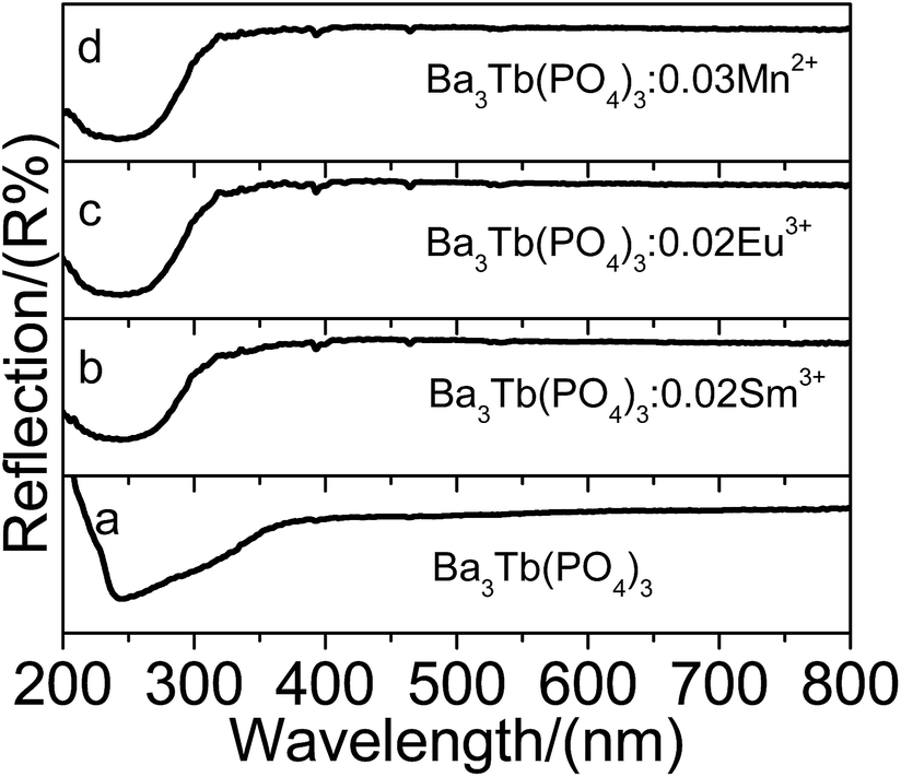 | ||
| Fig. 2 Diffuse reflection spectra of Ba3Tb(PO4)3 (a), Ba3Tb(PO4)3:0.02Sm3+ (b), Ba3Tb(PO4)3:0.02Eu3+ (c) and Ba3Tb(PO4)3:0.03Mn2+ (d). | ||
In order to explain the possibility of the Tb3+–Sm3+, Tb3+–Eu3+ and Tb3+–Mn2+ energy transfer, the luminescent properties of Ba3Tb(PO4)3 and Ba3Eu(PO4)3 were studied.
Fig. 3a described the emission and excitation spectra of Ba3Tb(PO4)3. Under 377 nm excitation, the spectrum display a series of emission lines ascribed to the intra-4f8 5D4–7F6−3 electronic transitions of Tb3+ ions. No emission lines from the 5D3 energy level is observed in the emission spectrum, and the reason can be attributed to high concentration of Tb3+ ions, which leads to the occurrence of cross-relaxation. The excitation spectrum of Ba3Tb(PO4)3 monitored with the 5D4–7F5 transition (545 nm) is analyzed in detail. The bands centered at 235 and 250–275 nm are assigned to the spin-allowed (low-spin, LS) and spin-forbidden (high-spin, HS) inter-configurational Tb3+ f–d transitions, respectively, and the remaining peaks are assigned to intra-4f8 transitions between the 7F6 and the 5F5,4, 5H7–4, 5D1,0, 5L10–7, 5G6–2, and 5D2–4 levels.22 The inset of Fig. 3a is a image of Ba3Tb(PO4)3 under 365 nm excitation, in which an intense green light can be observed.
 | ||
| Fig. 3 Spectral characteristics of Ba3Tb(PO4)3 (a), Ba3Eu(PO4)3 (b). Inset: image of Ba3Tb(PO4)3 (a) and Ba3Eu(PO4)3 (b) (λex = 365 nm). | ||
Fig. 3b presented the emission and excitation spectra of Ba3Eu(PO4)3. Monitored at 615 nm, the excitation spectrum of Ba3Eu(PO4)3 displays a weak broad band ranging from 200 to 280 nm, and some narrow peaks (287, 297, 319, 362, 382, 393, 415, 444 and 465 nm, respectively) resulting from the combined absorptions of host and Eu3+–O2− charge transfer (CT) transition, as well as 4f–4f characteristic transitions of Eu3+, respectively. Upon the excitation of f–f transition centered at 393 nm, the emission spectrum presents the characteristic emission lines deriving from the 4f–4f transitions of Eu3+ ions in Ba3Eu(PO4)3, namely, 5D0 excited states to the 7FJ ground states including 5D0–7F1 (596 nm), 5D0–7F2 (615 nm), 5D0–7F3 (656 nm) and 5D0–7F1 (707 nm), respectively.4–6 And the electric dipole transition 5D0–7F2 around 615 nm is much stronger than that of the other transitions of Eu3+. Therefore, the inset of Fig. 3b depicts Ba3Eu(PO4)3 shows an obvious red light.
Generally, Sm3+ doped phosphors can exhibit several orange-red emission peaks which are assigned to the 4G5/2 → 6HJ/2 (J = 5, 7 and 9) transitions of Sm3+. However, there is no emission of Ba3Sm(PO4)3 in our experiment. The reason should be attributed to high concentration of Sm3+ ions, which leads to the occurrence of cross-relaxation.28
Actually, Mn2+ ions doped eulytite-type orthophosphate can create orange-red emission under UV excitation, for example, our previous results show that Sr3La(PO4)3:Mn2+ present the orange-red light under 402 nm excitation, and the emission peak locates at 605 nm, therefore, we think that Mn2+ doped eulytite-type orthophosphate Ba3Tb(PO4)3 should emit orange-red or red light.23
In order to explore the energy transfer from Tb3+ to Sm3+, Eu3+ and Mn2+, a series of samples with the chemical composition of Ba3Tb1−x(PO4)3:xSm3+, Ba3Tb1−y(PO4)3:yEu3+ and Ba3−zTb(PO4)3:zMn2+ were synthesized and their luminescent properties were investigated.
Fig. 4 shows the emission and excitation spectra, and decay curves of Ba3Tb1−x(PO4)3:xSm3+. Upon excitation of the Tb3+ ion f–f transition peak at 377 nm, Fig. 4a depicts Ba3Tb(PO4)3:Sm3+ shows the typical Tb3+ and Sm3+ ion f–f emission lines. Moreover, with the lower Sm3+ concentration, there are both Tb3+ and Sm3+ emission peaks, and the emission intensities of Tb3+ decrease with increasing Sm3+ concentration, and the inset of Fig. 4a shows the emission intensities of Sm3+ have an obvious enhancement. When the Sm3+ concentration is higher than x = 0.02, not only the Tb3+ emission is very weak, but also the emission intensities of Sm3+ begin to decrease, the reason is the occurrence of cross-relaxation. And the results can also be seen from the upper image of phosphors. While the excitation spectrum of Sm3+ ions consists of typical Tb3+ and Sm3+ f–f excitation bands, and the excitation intensities, corresponding to Tb3+, directly decrease, however, for the Sm3+ excitation intensities (inset of Fig. 4b), there are an optimal value at 0.02 Sm3+. For the 545 nm emission of Ba3Tb1−x(PO4)3:xSm3+, Fig. 4c shows the corresponding excitation spectra, which show the excitation spectrum is similar to that of Ba3Tb(PO4)3 sample monitored with the 5D4–7F5 transition, however, the excitation intensities directly decrease with increasing Sm3+ concentration. The above results indicate the Tb3+–Sm3+ energy transfer in Ba3Tb(PO4)3 are valid.
 | ||
| Fig. 4 Emission (a, λex = 377 nm) and excitation (b, λem = 603 nm; c, λem = 545 nm) spectra of Ba3Tb1−x(PO4)3:xSm3+, decay curves of Ba3Tb1−x(PO4)3:xSm3+ (d, λex = 377 nm, λem = 545 nm). Inset: emission spectra of Sm3+ (a), excitation spectra of Sm3+ (b). Upper: image of Ba3Tb1−x(PO4)3:xSm3+ (λex = 365 nm). | ||
To further validate the process of energy transfer from Tb3+ to activators, under the 377 nm excitation of Tb3+, monitored at 545 nm emission of Tb3+, the decay curves of Ba3Tb1−x(PO4)3:xSm3+ are measured and shown in Fig. 4d. It is known when a donor transfers its energy to an acceptor, the temporal decay of the donor become fast. Fig. 4d shows fluorescence decay curve of Tb3+ with different Sm3+ concentration. If Tb3+ and Sm3+ work independently and there is no energy transfer from Tb3+ to Sm3+, the luminescence lifetime of both activators will be as same as in single doped samples. If there is energy transfer, the decay of Tb3+ excitation state will be accelerated by the energy transfer, and consequently the lifetime of Tb3+ will be shortened.
Fig. 5 presents the emission and excitation spectra, and decay curves of Ba3Tb1−y(PO4)3:yEu3+. Under 377 nm excitation of Tb3+, it can be observed that the emission spectra are composed of red (615 nm), orange (596 nm) and green (545 nm) light-emitting peaks, which agree well with the results of ref. 21. The orange and red emission peaks are attributed to the typical 5D0–7FJ (J = 1, 2) transition emission of Eu3+. The green emission peaks at 545 nm originate from the 5D4–7F5 transition of Tb3+. With increasing Eu3+ concentration, through there are both Tb3+ and Sm3+ emission peaks in the emission spectra, however, the emission intensities of Tb3+ straightly decrease, and that of Eu3+ directly increase (as shown in the inset of Fig. 5a). Viz., there is no concentration quenching effect in the region of our experiment. And the results can also be seen from the upper image of phosphors. For the 615 nm emission of Eu3+, Fig. 5b presents the excitation spectrum of Eu3+ ions consists of typical Tb3+ and Eu3+ f–f excitation bands, in the region of 200–300 nm, which agrees well with the results of ref. 21. Moreover, there is an obvious decrease of Tb3+ excitation intensity with increasing Eu3+ concentration. Differently, for the 545 nm emission of Ba3Tb1−y(PO4)3:yEu3+, as shown in Fig. 5c, the excitation spectrum presents a similar characteristics to that of Ba3Tb(PO4)3 sample monitored with the 5D4–7F5 transition, however, the excitation intensities directly decrease with increasing Eu3+ concentration. Therefore, This can prove an energy transfer from Tb3+ to Eu3+ in Ba3Tb(PO4)3:Eu3+. Moreover, Fig. 5d shows the decay curves of Ba3Tb1−y(PO4)3:yEu3+, and the results show that the lifetimes of Tb3+ become shorten with increasing Eu3+ concentration. As mentioned above, the results indicate that there should be the energy transfer from Tb3+ to Eu3+.
 | ||
| Fig. 5 Emission (a, λex = 377 nm) and excitation (b, λem = 615 nm; c, λem = 545 nm) spectra of Ba3Tb1−y(PO4)3:yEu3+, decay curves of Ba3Tb1−y(PO4)3:yEu3+ (d, λex = 377 nm, λem = 545 nm). Inset: emission spectra of Eu3+ (a). Upper: image of Ba3Tb1−y(PO4)3:yEu3+ (λex = 365 nm). | ||
Fig. 6 presents the emission and excitation spectra, and decay curves of Ba3−zTb(PO4)3:zMn2+. Under 377 nm excitation of Tb3+, the emission spectra show the emission characteristics of Tb3+ and Mn2+, and the emission intensities of Tb3+ decrease with increasing Mn2+ doping content, however, that of Mn2+ reaches a maximum as z equals 0.03 and then begins to decrease due to concentration quenching. And the results can also be seen from the upper image of phosphors. For the Mn2+ 596 nm emission, Fig. 6b shows the excitation spectrum presents the excitation characteristics of Tb3+, there is no an obvious excitation characteristics of Mn2+. Moreover, for the 545 nm emission of Ba3−zTb(PO4)3:zMn2+, as shown in Fig. 6c, there are the same excitation peaks between this samples and Ba3Tb(PO4)3, however, the excitation intensities directly decrease with increasing Mn2+ concentration. Therefore, this may be a direct evidence to demonstrate the energy transfer Tb3+–Mn2+ in the Ba3Tb(PO4)3 host. As shown in Fig. 6d, under the 377 nm excitation of Tb3+, monitored at 545 nm emission of Tb3+, the decay curves of Ba3−zTb(PO4)3:zMn2+ presents the decrease trend with increasing Mn2+ concentration, the results also prove the energy transfer from Tb3+ to Mn2+.
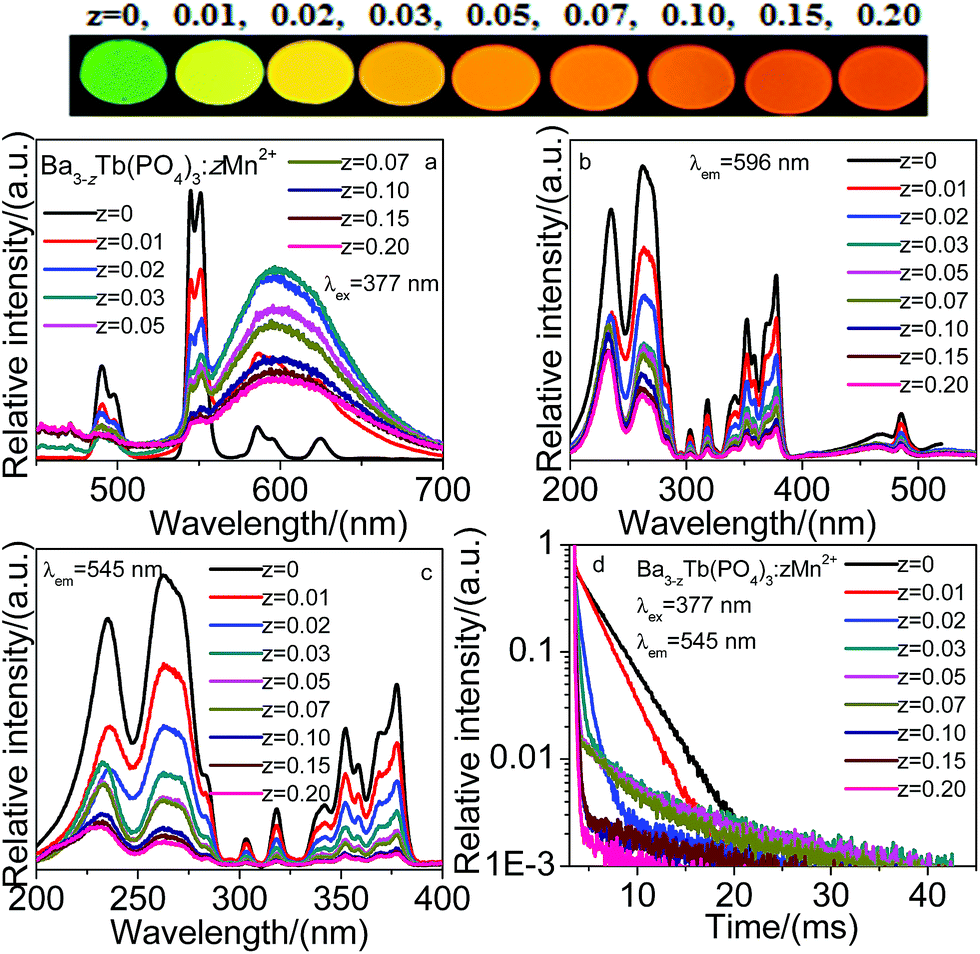 | ||
| Fig. 6 Emission (a, λex = 377 nm) and excitation (b, λem = 596 nm; c, λem = 545 nm) spectra of Ba3−zTb(PO4)3:zMn2+, decay curves of Ba3−zTb(PO4)3:zMn2+ (d, λex = 377 nm, λem = 545 nm). Upper: image of Ba3−zTb(PO4)3:zMn2+ (λex = 365 nm). | ||
Fig. 4–6a depicts the emission spectra for Ba3Tb1−x(PO4)3:xSm3+ (x = 0–0.15), Ba3Tb1−y(PO4)3:yEu3+ (y = 0–0.15) and Ba3−zTb(PO4)3:zMn2+ (z = 0–0.20) with different concentration of Sm3+, Eu3+ and Mn2+, respectively. We can observe the emission intensities of Tb3+ decrease with increasing Sm3+, Eu3+ and Mn2+ concentrations under 377 nm excitation, and the emission intensities of Sm3+ and Mn2+ in the Ba3Tb(PO4)3 systems clearly increase to the maximum at x = 0.02 and z = 0.03, respectively, and subsequently descend with respectively further concentration of Sm3+ and Mn2+ ions resulting from the concentration effects in Fig. 4a and 6a. Differently, the emission intensity of Eu3+ keeps an obvious increase with increasing Eu3+ concentration in Fig. 5a. In order to illuminate the results, these detailed variations of Ba3Tb(PO4)3 and activators emission intensities are presented in Fig. 7.
 | ||
| Fig. 7 Variation of emission intensity of Tb3+ and activators on concentrations in Ba3Tb1−x(PO4)3:xSm3+ (a), Ba3Tb1−y(PO4)3:yEu3+ (b) and Ba3−zTb(PO4)3:zMn2+ (c) (λex = 377 nm). | ||
The energy transfer efficiencies (ηT) from the Tb3+ to activators in Ba3Tb1−x(PO4)3:xSm3+, Ba3Tb1−y(PO4)3:yEu3+ and Ba3−zTb(PO4)3:zMn2+ systems were calculated using the equation29–31
| ηT = 1 − (I/I0) | (2) |
 | ||
| Fig. 8 Energy transfer efficiencies (ηT) from Tb3+ to activators on concentrations in Ba3Tb1−x(PO4)3:xSm3+ (a), Ba3Tb1−y(PO4)3:yEu3+ (b) and Ba3−zTb(PO4)3:zMn2+ (c) (λex = 377 nm). | ||
As mentioned above, the shorten lifetime of Tb3+ confirms the energy transfer from Tb3+ to activators (Sm3+, Eu3+ and Mn2+) ions. The decay curves for Ba3Tb(PO4)3 can be fitted into a single exponential function as32
I = I0![[thin space (1/6-em)]](https://www.rsc.org/images/entities/char_2009.gif) exp(−t/τ) exp(−t/τ)
| (3) |
|
I = A1exp(−t/τ1) + A2exp(−t/τ2)
| (4) |
| τ* = (A1τ12 + A2τ22)/(A1τ1 + A2τ2) | (5) |
For Ba3Tb1−x(PO4)3:xSm3+, Ba3Tb1−y(PO4)3:yEu3+ and Ba3−zTb(PO4)3:zMn2+, the calculated average lifetimes (τ*) are listed in Table S1.† The results present that the temporal decay of Tb3+ become fast with increasing the activators concentration. In the case of energy transfer, the luminescence lifetime of a sensitizer is shortened, because there are additional decay channels that shorten the lifetime of the excited state. Therefore, the decay lifetime of Tb3+ ions can be found to decrease with increase activators ions content, which is strong evidence for the energy transfer from the Tb3+ to activators.
3.3 Energy transfer mechanism
In order to determine the energy transfer mechanisms from Tb3+ to activators in Ba3Tb(PO4)3:Sm3+, Ba3Tb(PO4)3:Eu3+ and Ba3Tb(PO4)3:Mn2+ samples, it is necessary to know the critical distance (Rc) between activators such as Sm3+, Eu3+ and Mn2+. With the increasing Sm3+, Eu3+ and Mn2+ contents, the energy transfer from Tb3+ to activators becomes more efficient, and the probability of energy migration between activators increases simultaneously. When the distance is small enough, the concentration quenching occurs and the energy migration is hindered. The Rc value can be roughly assessed by the calculation pointed out by Blasse36| Rc = 2[3V/(4πXcN)]1/3 | (6) |
| (ηS0/η) ∝ Cα/3 | (7) |
| (IS0/I) ∝ Cα/3 | (8) |
For Ba3Tb(PO4)3:Sm3+, Ba3Tb(PO4)3:Eu3+ and Ba3Tb(PO4)3:Mn2+, the relationship between IS0/I and Cα/3 based on the above equation is illustrated in Fig. 9a–j, which can be respectively fitted using straight line. One can find that all the biggest R2 values of the linear fittings occur when α = 6 in Fig. 9a–j, corresponding to the best linear behaviours (a, d, h). Therefore, the energy transfers from the Tb3+ to Sm3+, Eu3+ and Mn2+ ions take place through the dipole–dipole mechanisms.
 | ||
| Fig. 9 Dependence of IS0/IS of Tb3+ (a, d, h) C6/3, (b, e, i) C8/3, and (c, f, j) C10/3. | ||
Fig. 10 shows a simple model expressing the energy transfer from Tb3+ to Sm3+, Eu3+ and Mn2+ ions and the characteristic emission energy levels of Sm3+, Eu3+ and Mn2+ in Ba3Tb(PO4)3. In Sm3+, Eu3+ and Mn2+ doped Ba3Tb(PO4)3 samples, upon 377 nm radiation, Ba3Tb(PO4)3 absorb UV radiation and then it transfer the energy to Sm3+, Eu3+ and Mn2+ ions, which results in the increases of characteristic emission intensities of activators.
 | ||
| Fig. 10 A simple model expressing the energy transfer from Tb3+ to activators (Sm3+, Eu3+, Mn2+). | ||
| Samples | CIE (X, Y) | CCT (K) | QE (%) |
|---|---|---|---|
| Ba3Tb(PO4)3 | (0.3196, 0.6009) | 5889 | 51.2 |
| Ba3Eu(PO4)3 | (0.6469, 0.3511) | 1048 | 59.2 |
| x = 0.001 | (0.3794, 0.5652) | 4759 | 20.7 |
| x = 0.005 | (0.3993, 0.5519) | 4420 | 27.6 |
| x = 0.01 | (0.4695, 0.4977) | 3163 | 36.9 |
| x = 0.02 | (0.4951, 0.4780) | 2727 | 41.6 |
| x = 0.03 | (0.5225, 0.4557) | 2301 | 37.1 |
| x = 0.05 | (0.5352, 0.4452) | 2124 | 33.8 |
| x = 0.07 | (0.5380, 0.4406) | 2073 | 30.6 |
| x = 0.10 | (0.5489, 0.4324) | 1940 | 27.3 |
| x = 0.15 | (0.5586, 0.4220) | 1813 | 22.6 |
| y = 0.001 | (0.3897, 0.5544) | 4398 | 35.7 |
| y = 0.005 | (0.4313, 0.5242) | 3837 | 40.3 |
| y = 0.01 | (0.4794, 0.4832) | 2948 | 44.3 |
| y = 0.02 | (0.5079, 0.4582) | 2460 | 47.9 |
| y = 0.03 | (0.5545, 0.4210) | 1835 | 48.6 |
| y = 0.05 | (0.5692, 0.4073) | 1665 | 52.1 |
| y = 0.07 | (0.6025, 0.3900) | 1401 | 57.9 |
| y = 0.10 | (0.6255, 0.3706) | 1212 | 65.6 |
| y = 0.15 | (0.6455, 0.3528) | 1060 | 70.3 |
| z = 0.001 | (0.3898, 0.5598) | 4519 | 19.6 |
| z = 0.005 | (0.4106, 0.5462) | 3912 | 23.8 |
| z = 0.01 | (0.4497, 0.5062) | 3481 | 29.5 |
| z = 0.02 | (0.4877, 0.4792) | 2821 | 41.3 |
| z = 0.03 | (0.5410, 0.4445) | 2072 | 49.8 |
| z = 0.05 | (0.5519, 0.4364) | 1941 | 45.6 |
| z = 0.07 | (0.5705, 0.4213) | 1731 | 40.1 |
| z = 0.10 | (0.5839, 0.4139) | 1613 | 32.3 |
| z = 0.15 | (0.5696, 0.4268) | 1767 | 27.9 |
| z = 0.20 | (0.5502, 0.4204) | 1862 | 25.3 |
3.4 CIE chromaticity coordinate and quantum efficiency
Table 1 depicts the corresponding CIE (Commission Internationale de I'Eclairage 1931 chromaticity) coordinates positions and quantum efficiencies for the as-prepared Ba3Tb1−x(PO4)3:xSm3+ (x = 0–0.15), Ba3Tb1−y(PO4)3:yEu3+ (y = 0–0.15) and Ba3−zTb(PO4)3:zMn2+ (z = 0–0.20) samples under 365 nm UV excitation (the emission color of phosphors can be seen from Fig. 4–6). It can be found that the Ba3Tb1−x(PO4)3:xSm3+ can emit green to orange-red light, and their chromaticity coordinate varies from (0.3794, 0.5652) (x = 0.001) to (0.5586, 0.4420) (x = 0.15). The Ba3Tb1−y(PO4)3:yEu3+ can emit green to bright red, whose chromaticity coordinate changes from (0.3897, 0.5544) (y = 0.001) to (0.6455, 0.3528) (y = 0.15). The Ba3−zTb(PO4)3:zMn2+ (z = 0–0.20) show the luminescence color varies from green to orange-red, for example, the chromaticity coordinate is from (0.3898, 0.5598) (z = 0.001) to (0.5502, 0.4204) (z = 0.20). Moreover, in all phosphors, the maximum quantum efficiency is 70.3% for Ba3Tb0.85(PO4)3:0.15Eu3+.4. Conclusions
In summary, a series of Eu3+, Sm3+ and Mn2+ ion doped Ba3Tb(PO4)3 phosphors were synthesized via the conventional high temperature solid state method. Ba3Tb(PO4)3 presents a cubic unit cell with space group Ī43d. Under 7F6–5D3 of Tb3+ excitation 377 nm, the emission intensities of Ba3Tb(PO4)3:Sm3+, Ba3Tb(PO4)3:Eu3+ and Ba3Tb(PO4)3:zMn2+ can be adjusted by changing the activators concentrations, and their emission color can also tuned from green to red or orange-red, which are attributed to the efficient energy transfer from Tb3+ to Sm3+, Eu3+ and Mn2+, respectively. The energy transfer mechanism was demonstrated to be the electric dipole–dipole interaction, and the best quantum efficiencies are 41.6%, 70.3% and 49.8% for Ba3Tb(PO4)3:Sm3+, Ba3Tb(PO4)3:Eu3+ and Ba3Tb(PO4)3:Mn2+ respectively. The results indicate that the phosphor may serve as potential red or orange-red emitting material for n-UV based white LEDs.Acknowledgements
The work is supported by the National Natural Science Foundation of China (No. 50902042), the Funds for Distinguished Young Scientists of Hebei Province, China (No. A2015201129), the Natural Science Foundation of Hebei Province, China (Nos A2014201035, E2014201037), the Education Office Research Foundation of Hebei Province, China (Nos ZD2014036, QN2014085), the Midwest Universities Comprehensive Strength Promotion Project.Notes and references
- Q. Zhou, Y. Zhou, Y. Liu, L. Luo, Z. Wang, J. Peng, J. Yan and M. Wu, J. Mater. Chem. C, 2015, 3, 3055–3059 RSC.
- M. Peng, X. Yin, P. A. Tanner, M. G. Brik and P. Li, Chem. Mater., 2015, 27(8), 2938–2945 CrossRef.
- Y. Wang, T. Wen, L. Tang, L. Yang, W. Yang and Y. Zhao, Dalton Trans., 2015, 7578–7585 RSC.
- J. Zhong, D. Chen, W. Zhao, Y. Zhou, H. Yu, L. Chen and Z. Ji, J. Mater. Chem. C, 2015, 3, 4500–4510 RSC.
- H. Ji, Z. Huang, Z. Xia, M. S. Molokeev, X. Jiang, Z. Lin and V. V. Atuchin, Dalton Trans., 2015, 7679–7686 RSC.
- F. Baur, F. Glocker and T. Jüstel, J. Mater. Chem. C, 2015, 3, 2054–2064 RSC.
- F. Kang, Y. Zhang and M. Peng, Inorg. Chem., 2015, 54(4), 1462–1473 CrossRef CAS PubMed.
- J. Zhang, Y. Liu, L. Li, N. Zhang, L. Zou and S. Gan, RSC Adv., 2015, 5, 29346–29352 RSC.
- D. Wen, J. Feng, J. Li, J. Shi, M. Wu and Q. Su, J. Mater. Chem. C, 2015, 3, 2107–2114 RSC.
- X. Min, Z. Huang, M. Fang, Y.-G. Liu, C. Tao and X. Wu, Inorg. Chem., 2014, 53, 6060–6065 CrossRef CAS PubMed.
- K. Li, X. Liu, Y. Zhang, X. Li, H. Lian and J. Lin, Inorg. Chem., 2015, 54(1), 323–333 CrossRef CAS PubMed.
- D. Kang, H. S. Yoo, S. H. Jung, H. Kim and D. Y. Jeon, J. Phys. Chem. C, 2011, 115, 24334–24340 CAS.
- Y.-C. Fang, S.-Y. Chu, P.-C. Kao, Y.-M. Chuang and Z.-L. Zeng, J. Electrochem. Soc., 2011, 158, J1–J5 CrossRef CAS PubMed.
- N. S. Singh, R. S. Ningthoujam, G. Phaomei, S. D. Singh, A. Vinu and R. K. Vatsa, Dalton Trans., 2012, 4404–4412 RSC.
- M. Shang, C. Li and J. Lin, Chem. Soc. Rev., 2014, 43, 1372–1386 RSC.
- W. Lü, W. Lv, Q. Zhao, M. Jiao, B. Shao and H. You, J. Mater. Chem. C, 2015, 3, 2334–2340 RSC.
- W. B. Dai, RSC Adv., 2014, 4, 11206–11215 RSC.
- C. Zhang, H. Liang, S. Zhang, C. Liu, D. Hou, L. Zhou, G. Zhang and J. Shi, J. Phys. Chem. C, 2012, 116, 15932–15937 CAS.
- N. Guo, Y. Jia, W. Lü, W. Lv, Q. Zhao, M. Jiao, B. Shao and H. You, Dalton Trans., 2013, 5649–5654 RSC.
- N. Guo, Y. Huang, Y. Jia, W. Lv, Q. Zhao, W. Lü, Z. Xia and H. You, Dalton Trans., 2013, 941–947 RSC.
- V. B. Mikhailik and H. Kraus, J. Lumin., 2009, 129, 945–947 CrossRef CAS PubMed.
- Y. Jia, W. Lü, N. Guo, W. Lü, Q. Zhao and H. You, Phys. Chem. Chem. Phys., 2013, 15, 6057–6062 RSC.
- Z. Wang, S. Lou and P. Li, J. Lumin., 2014, 156, 87–90 CrossRef CAS PubMed.
- T. W. Kuo and T. M. Chen, J. Electrochem. Soc., 2010, 157, J216–J220 CrossRef CAS PubMed.
- M. Jiao, N. Guo, W. Lü, Y. Jia, W. Lv, Q. Zhao, B. Shao and H. You, Dalton Trans., 2013, 12395–12402 RSC.
- X. Chen, Z. Gong, Q. Wan, S. Wu, F. Guo, N. Zhuang and J. Chen, Opt. Mater., 2015, 44, 48–53 CrossRef CAS PubMed.
- Z. Xia, Y. Zhang, M. S. Molokeev and V. V. Atuchin, J. Phys. Chem. C, 2013, 117, 20847–20854 CAS.
- H. Lin, E. Y. B. Pun, L. H. Huang and X. R. Liu, Appl. Phys. Lett., 2002, 80, 2642–2644 CrossRef CAS PubMed.
- W.-J. Yang and T.-M. Chen, Appl. Phys. Lett., 2006, 88, 101903 CrossRef PubMed.
- K. H. Kwon, W. B. Im, H. S. Jang, H. S. Yoo and D. Y. Jeon, Inorg. Chem., 2009, 48, 11525–11532 CrossRef CAS PubMed.
- P. I. Paulose, G. Jose, V. Thomas, N. V. Unnikrishnan and M. K. R. Warrier, J. Phys. Chem. Solids, 2003, 64, 841–846 CrossRef CAS.
- W. J. Yang, L. Luo, T. M. Chen and N. S. Wang, Chem. Mater., 2005, 17, 3883–3888 CrossRef CAS.
- C.-H. Huang, T.-M. Chen, W.-R. Liu, Y.-C. Chiu, Y.-T. Yeh and S.-M. Jang, ACS Appl. Mater. Interfaces, 2010, 2, 259–264 CAS.
- C.-H. Huang and T.-M. Chen, J. Phys. Chem. C, 2011, 115, 2349–2355 CAS.
- C. H. Huang and T.-M. Chen, Opt. Express, 2010, 18, 5089–5099 CrossRef CAS PubMed.
- G. Blasse, Phys. Lett. A, 1968, 28, 444–445 CrossRef CAS.
- G. Blasse and B. C. Grabmaier, Luminescent Materials, Springer, Berlin, 1994 Search PubMed.
- D. L. Dexter and J. H. Schulman, J. Chem. Phys., 1954, 22, 1063–1070 CrossRef CAS PubMed.
- R. Reisfeld, E. Greenberg, R. Velapoldi and B. Barnett, J. Chem. Phys., 1972, 56, 1698–1705 CrossRef CAS PubMed.
- U. Caldiňo, J. L. Hernández-Pozos, C. Flores, A. Speghini and M. Bettinelli, J. Phys.: Condens. Matter, 2005, 17, 7297–7306 CrossRef.
- J. Zhang, Y. He, Z. Qiu, W. Zhang, W. Zhou, L. Yu and S. Lian, Dalton Trans., 2014, 18134–18145 RSC.
Footnote |
| † Electronic supplementary information (ESI) available. See DOI: 10.1039/c5ra12619c |
| This journal is © The Royal Society of Chemistry 2015 |