 Open Access Article
Creative Commons Attribution 3.0 Unported Licence
Chemical vapor deposition of high charge carrier mobility benzothiadiazole-based conjugated polymer thin films†
Marek K. Charyton a,
Jonathan Crêpellièrea,
Kamil Kotwica
 bc,
Monika Gorad,
William Lea,
Gilles Frachea,
Patrick Grysana,
Jérôme Guillota,
Kamal Baba
 a and
Nicolas D. Boscher
 *a
*a
aMaterials Research and Technology Department, Luxembourg Institute of Science and Technology, L-4362 Esch-sur-Alzette, Luxembourg. E-mail: nicolas.boscher@list.lu
bFaculty of Chemistry, Warsaw University of Technology, 00-664 Warszawa, Poland
cInstitute of Physical Chemistry, Polish Academy of Sciences, 01-224 Warszawa, Poland
dFaculty of Chemistry, University of Warsaw, 02-093 Warszawa, Poland
First published on 4th July 2024
Abstract
Low band gap benzothiadiazole–oligothiophene conjugated polymer thin films are prepared using oxidative chemical vapor deposition (oCVD). The synthesis and deposition occur simultaneously from the gas phase in oCVD; no solubilizing groups are attached to the benzothiadiazole or thienyl moieties, which allows molecular packing and charge carrier mobility to increase. Moreover, oCVD, which is a solventless, scalable and substrate independent approach, readily leads to the formation of dense and low surface roughness benzothiadiazole–oligothiophene conjugated polymer thin films. Polymerization yield, doping and conductivity of the benzothiadiazole–oligothiophene conjugated polymers are shown to be strongly influenced by the oxidant-to-monomer ratio. Interestingly, benzothiadiazole–oligothiophene conjugated polymer thin films synthesized by oCVD exhibit hole mobilities up to 4.0 cm2 V−1 s−1, surpassing those of previously reported benzothiadiazole–oligothiophene conjugated polymers prepared by spin-coating, dip-coating and drop casting.
Introduction
2,1,3-Benzothiadiazole (BT) is a strong electron-accepting building block widely used for the engineering of molecules1–3 and conjugated polymers4–12 for electronic13 and optoelectronic devices,1 including organic field-effect transistors (OFETs)2 and organic solar cells.4–6,10,12,14 BT is notably often copolymerized with oligothiophenes and other thiophene derivatives to form donor–acceptor (D–A) p-type conjugated polymers6–10,12,13 combining a low band gap and high hole mobility.2,8,15Benzothiadiazole–oligothiophene D–A conjugated polymers are mainly synthesised by Stille coupling polymerization,8 Suzuki coupling polymerization16 and Sonogashira coupling polymerization,17 which involve halogenation steps and palladium catalysts such as palladium-tetrakis(triphenylphosphine) (Pd(PPh3)4).18 In addition to the organic solvents used during the multiple synthetic steps, e.g. dimethylformamide,8 toluene19 and tetrahydrofuran,8,12 organic solvents such as chloroform,12 chlorobenzene12 or dichlorobenzene8,12 are required for the integration of the conjugated polymers using spin-coating,8 dip-coating12,19 or drop casting.8 Although organic solvents are used in all steps, i.e. synthesis and integration, long alkyl substituents are still required to ensure the processability of these conjugated polymers.8,10,12,17,20–24 Precisely, hexylphenyl,24 octylphenyl,24 octyl,8,12,21 octyloxy,8,21 nonyl,17 dodecyl,21,24 hexadecyl,23 octyldodecyl,20,22 nonyltridecyl20 and decyltetradecyl20 are commonly grafted to the thiophenes and thiophene derivatives to ensure a balance between solubility and aggregation which is crucial for the charge transport performances of the conjugated polymer thin films.20 Indeed, if the molecular weight has a strong influence on the electronic properties of benzothiadiazole–oligothiophene D–A conjugated polymers,15,20,23 π–π intermolecular interactions are essential for high hole mobilities.15,20 Short alkyl side groups induce poor solubility and strong aggregation, making the formation of uniform conjugated polymer thin films difficult, while long alkyl side groups do not allow the aggregation strength required to reach the targeted performances to be achieved. Therefore, a trade-off between the solubility of the polymer chains and their aggregation or π–π stacking in the solid state is always needed.8,10,12,17,20–24 In that sense, simple linear alkyl side groups, e.g. octyl8,12,21 and dodecyl,21,24 are preferred to bulkier solubilizing groups like hexylphenyl24 and octylphenyl.24 Yet, any integration of solubilizing side groups, by nature, weakens the intermolecular packing of the polymer chains and therefore the charge transport properties.
Several groups reported that the electropolymerization of 4,7-dithien-2-yl-2,1,3-benzothiadiazole (DTBT),11,25,26 as well as several other benzothiadiazole–thiophene derivatives also bearing no solubilizing side groups,11,26 readily leads to the formation of benzothiadiazole–oligothiophene conjugated polymer thin films. Interestingly, the conjugated polymer thin films, which possess electrochromic properties,25 were demonstrated to be useful as stable photocathodes for photocatalytic oxygen reduction.11 Yet, the electropolymerization of benzothiadiazole–thiophene derivatives, which implies the use of electrically conductive substrates such as indium-tin oxide (ITO) or fluorine-doped tin oxide (FTO) coated glass,11,25 and is conducted in acetonitrile11,25 or benzonitrile26 with admixtures of tetrabutylammonium hexafluorophosphate,11 tetrabutylammonium perchlorate25,26 or tetrabutylammonium tetrafluoroborate,26 is not entirely suitable for the preparation of OFETs and organic solar cells. Moreover, the resulting benzothiadiazole–oligothiophene conjugated polymer thin films exhibit rough and powdery surfaces poorly suitable for OFETs and photovoltaic applications,25,26 which can only be slightly smoothened using long alkyl side groups.26
On the other hand, chemical vapor deposition (CVD), broadly implemented in the semiconductor industry, can be used to produce high-quality and high-performance thin films on various substrates.27–29 In particular, oxidative chemical vapor deposition (oCVD) allows the simultaneous synthesis and deposition of conjugated polymer thin films directly from the vapor phase,29,30 suppressing the need for both solvents and side groups. Interestingly, the absence of solubilizing groups allows reducing the intermolecular distances in conjugated polymer thin films, which can yield superior charge carrier density and mobility, improved delocalization and electrical conductivities.31–33 Such a feature was previously exploited to increase the lifetime of electronically excited states,34 and enhance the sensing35 and catalytic properties36 of conjugated polymer thin films prepared via the oCVD of polycyclic aromatic compounds. Upon reaction with a suitable oxidizing agent,29,37–39 both simple electron-rich monoaromatic compounds30,32,38,40 and polycyclic aromatic compounds31,34–36,39 can be polymerized via oCVD. A recent report has demonstrated that conjugated polymer thin films can even be grown from electron-poor aromatic compounds, e.g. diketopyrrolopyrrole,34 provided that they are functionalized with electron-rich groups that provide active sites enabling intermolecular oxidative polymerization. In this work, we report for the first time the preparation of benzothiadiazole–oligothiophene D–A conjugated polymer thin films using oCVD. With the aim to increase molecular packing and charge mobility, no solubilizing groups were attached to the benzothiadiazole or thienyl moieties. The occurrence of the oxidative coupling reaction was evidenced by ultraviolet-visible-near infrared (UV/Vis/NIR) spectroscopy and laser desorption ionization high-resolution mass spectrometry (LDI-HRMS). Optimisation of the oxidant-to-monomer ratio readily allows enhancement of the polymerization yield, doping and conductivity of the conjugated polymer thin films. Interestingly, dense and low surface roughness benzothiadiazole–oligothiophene D–A conjugated polymer thin films exhibit a hole mobility (4.0 cm2 V−1 s−1) that surpasses those of previously reported benzothiadiazole–thiophene conjugated polymers.8,20–22
Results and discussion
Gas phase synthesis of benzothiadiazole-based conjugated polymers
2,1,3-Benzothiadiazole (BT), which is a strong electron-accepting unit, was symmetrically substituted with electron-rich thienyl groups to provide active sites for oxidative polymerization. The resulting donor–acceptor monomer (Scheme 1), i.e. 4,7-dithien-2-yl-2,1,3-benzothiadiazole (DTBT), was obtained using a previously reported Stille coupling procedure.11,13 The oCVD reaction of DTBT with iron(III) chloride (FeCl3), selected due to its ability to promote the dehydrogenative coupling of thienyl-substituted compounds,29,34 was carried out under vacuum (10−3 mbar) in a custom-built oCVD reactor (Scheme S1, ESI†).41 Briefly, DTBT and FeCl3 were concomitantly sublimed towards a heated substrate holder (100 °C) using two low temperature evaporators. In order to optimise the polymerization, doping and side reactions associated with the oCVD reaction of DTBT and FeCl3, different sublimation temperatures were investigated for the supply of FeCl3 (Table S1, ESI†), enabling the investigation of oxidant-to-monomer molar ratios ranging from 3 to 30.Irrespective of the oxidant-to-monomer ratio, the oCVD reaction of DTBT with FeCl3 leads to the formation of deep blue thin films (denoted pDTBT), which contrasts with the light orangish color of the coating obtained from the sublimation of DTBT (denoted sDTBT (0)) (Fig. 1). In addition, in contrast to the soluble sublimed sDTBT coating, the oCVD pDTBT thin films are almost insoluble in common organic solvents such as THF, acetone, dichloromethane, or hexafluoroisopropanol. The color change, from orange to blue, and the insolubility of the oCVD pDTBT thin films suggest the expansion of the chromophore structure and the polymerization of DTBT in oCVD. Indeed, Gańczarczyk et al. recently reported that electropolymerized DTBT exhibits a blue-violet color,11 whereas the parental DTBT monomer exhibits a yellow-orange color.
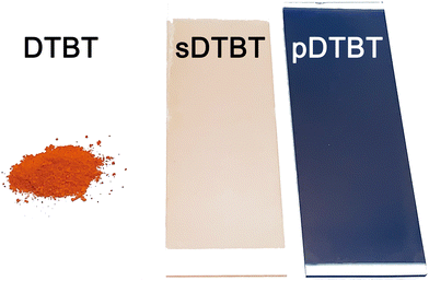 | ||
| Fig. 1 Optical images of the DTBT monomer powder (orange), the sublimed sDTBT (0) coating (orange) and oCVD pDTBT (13) coating (blue) prepared from DTBT on glass substrates. | ||
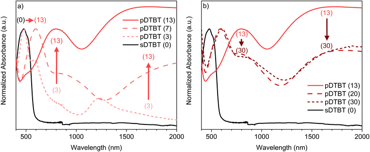
UV/Vis/NIR spectroscopic analysis of the thin films deposited on borosilicate glass substrates confirms differences in the absorption spectrum of the blue oCVD pDTBT thin films with respect to that of the orange sublimed sDTBT (0) coating (Fig. 2). Particularly, upon reaction with FeCl3, the main absorption band in sDTBT (0),13 assigned to the intramolecular charge transfer (ICT) between the donor and acceptor moieties of DTBT (Scheme 1),41 undergoes a progressive bathochromic shift from 475 nm to 600 nm in pDTBT.13,25 This bathochromic shift, associated with a reduction of the band gap, suggests the enlargement of the conjugation length in relation to the oxidative polymerization of DTBT. Yet, the intensity of the band observed at 475 nm for pDTBT (3), indicates the presence of unreacted DTBT monomer units (Fig. 2a) and therefore an incomplete polymerization for the coating elaborated from the lowest oxidant-to-monomer ratio. On the other hand, the UV/Vis/NIR spectra of the oCVD pDTBT thin films elaborated with oxidant-to-monomer ratios superior to 7 evidence a full disappearance of the absorption band at 475 nm assigned to the DTBT monomer (Fig. 2), which indicate a complete polymerization under these conditions. Upon further increase of the oxidant-to-monomer ratio, two bands with increasing intensity are observed at around 850 nm and 1500 nm (Fig. 2a). These bands are ascribed to the chemical doping of the thin films by FeCl3 with the peak at 850 nm corresponding to polarons and the absorption peak in the near-infrared region corresponding to the bipolarons.13,42 Noteworthily, after reaching a maximum intensity for pDTBT (13), the intensities of the two peaks related to the formation of polarons and bipolarons are observed to decrease for higher oxidant-to-monomer ratios, i.e. pDTBT (20) and pDTBT (30) (Fig. 2b). The oCVD pDTBT thin films elaborated from the highest oxidant-to-monomer ratios are therefore in a heavily doped state due to the incorporation of Cl− counterions within the polymer chains.
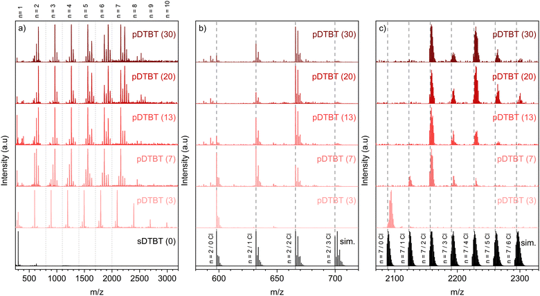
Irrespective of the oxidant-to-monomer ratio, the LDI-HRMS analysis directly acquired from the oCVD pDTBT thin films suggests the formation of DTBT oligomers (Fig. 3a). Unfortunately, the absence of solubilizing groups attached to the benzothiadiazole or thienyl moieties prohibits the solubilization of the oCVD pDTBT thin films and their characterisation by gel permeation chromatography (GPC) and the evaluation of the molecular weight of the formed polymers. Nevertheless, the HRMS peaks from the dimeric region perfectly match with the simulated isotopic patterns of [(DTBT)2–(H2) + (Cl)n–(H)n]+, with n lying between 0 and 2 (Fig. 3b), undoubtedly confirming the possibility of the oxidative polymerization of DTBT occurring under oCVD conditions. Alongside the oxidative polymerization reaction, peak distributions separated by 35 mass units related to the exchange of hydrogen by chlorine atoms are observed for the oCVD pDTBT thin films elaborated for oxidant-to-monomer ratios superior to 3 (Fig. 3b and c). In the case of pDTBT (3), polymerization occurs with little chlorine integration, such as demonstrated the HRMS spectra of the dimeric and heptameric regions (Fig. 3b and c). Chlorination begins with the increase of the oxidant-to-monomer ratio above 3 and the dimeric region of the HRMS spectra of the pDTBT (7) and pDTBT (13) samples are dominated by peak distributions ascribed to mono- and di-chlorinated DTBT dimers, respectively (Fig. 3b). Further increase of the oxidant-to-monomer ratio strengthens the peak distribution related to the di-chlorinated dimer over its non-chlorinated and mono-chlorinated counterparts. Although the intensities related to the different species detected in LDI-HRMS are not directly related to their abundance, they provide informative trends, and the LDI-HRMS analysis of the oCVD pDTBT thin films confirms the previously reported strong dependence of the chlorination reaction on the oxidant-to-monomer ratio.37 Interestingly, even for the sample prepared from the highest oxidant-to-monomer ratio, pDTBT (30), only a very weak signal is detected for the tri-chlorinated dimer (Fig. 3b). This suggests a facile integration of the first and second chlorine atoms, possibly on position 5 of the thienyl groups, while any subsequent chlorination occurs at a slower reaction rate.
A careful analysis of the peak distributions from the heptameric region and their comparison with the simulated isotopic patterns of [(DTBT)7–(H2)6 + (Cl)n–(H)n]+, with n lying between 0 and 6, reveals a mismatch between the experimental and calculated peaks for linear heptamers (Fig. 3c). In contrast to the perfect match observed for the dimeric region (Fig. 3b), the experimental HRMS spectra include the contribution of the peaks located at slightly higher masses compared to the theoretical isotopic patterns of [(DTBT)7–(H2)6 + (Cl)n–(H)n]+ (Fig. 3c). The high resolution of the LDI-HRMS technique (up to 0.003 amu) enables unambiguously assigning these higher mass contributions to closely stacked oligomers with n < 7. Strong interchain interactions yield the formation of non-covalent DTBT oligomer clusters that interfere with the characterisation of the DTBT heptamers.
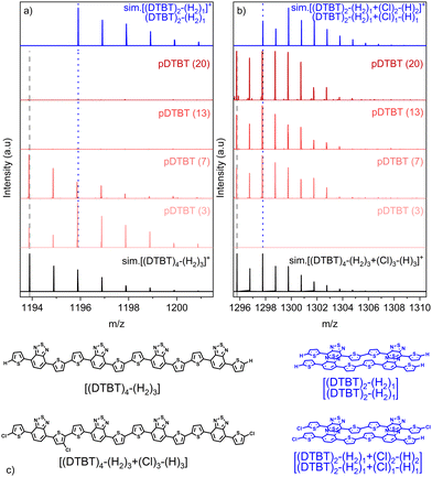
Analysis of the non-chlorinated and tri-chlorinated peaks of the tetramer region of the HRMS spectra (Fig. 4) well illustrates the dependence of the targeted polymerization reaction and chlorination side reaction on the oxidant-to-monomer ratio and correlates with the UV/Vis/NIR observations (Fig. 2). For very low oxidant-to-monomer ratios, i.e. pDTBT (3), the polymerization is limited by the lack of oxidants as is evidenced by the incomplete transition of the band related to the DTBT monomer at 475 nm to the polymeric one at 600 nm (Fig. 2a), as well as by the presence of non-chlorinated stacked dimers on the HRMS spectrum (Fig. 4a). On the other hand, for high oxidant-to-monomer ratios, polymerization is likely limited by the chlorination of the thienyl end groups due to an excess of oxidants. For excessively high oxidant-to-monomer ratios, i.e. pDTBT (20) and pDTBT (30), the reduced polymerization yield is expressed by a downtrend of the absorption in the NIR region in relation to the lower formation of polarons and bipolarons. Yet, chlorination does not seem to induce important steric hindrance or significantly affect π–π stacking since clusters of stacked mono- and di-chlorinated dimers are also detected by LDI-HRMS (Fig. 4b).
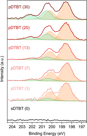
The HRMS observations are supported by the XPS Cl 2p core level analysis of the pDTBT samples (Fig. 5). For very low oxidant-to-monomer ratios, i.e. pDTBT (3), metal chloride environment (Cl 2p3/2 = ca. 198.6 eV and Cl 2p1/2 = ca. 200.2 eV) makes the main contribution (ca. 90%) to the Cl 2p spectrum. Upon increase of the oxidant-to-monomer ratio, the contribution of the organic chloride environment (Cl 2p3/2 = ca. 200.5 eV and Cl 2p1/2 = ca. 202.1 eV) becomes more significant, particularly for pDTBT (20) and pDTBT (30) for which organic chloride accounts for one quarter to one third of the overall chlorine content.
High charge carrier mobility poly(benzothiadiazole-dithiophene) thin films
Besides the synthesis of unreported conjugated polymers,34,43 one of the most important advantages of the oCVD approach is the ability to deposit the synthesised conjugated polymers directly in the thin film form to readily exploit their functional properties.29,35,36,44 In the present work, 100 nm thick oCVD pDTBT thin films were readily deposited on glass substrates (Fig. 1) and silicon wafers for the purpose of characterisation. Cross-sectional scanning electron microscopy (SEM) observations of the oCVD pDTBT thin films deposited on silicon wafers reveal the formation of rather dense coatings (Fig. 6a). Top-view SEM analysis evidences the rugged or granular surface of the oCVD pDTBT thin films (Fig. 6b and Fig. S1, ESI†). Upon increasing the oxidant-to-monomer ratio, the size of the main features observed at the surface was shown to increase (Fig. S1, ESI†). | ||
| Fig. 6 High magnification (a) cross-sectional and (b) top view SEM images and (c) AFM topography image of a 100 nm thick oCVD pDTBT (13) coating prepared from DTBT on silicon wafer. | ||
Atomic force microscopy (AFM) confirmed the granular nature of the surface of the oCVD pDTBT thin films (Fig. 6c and Fig. S1, ESI†). Increase of the grain size upon increasing the oxidant-to-monomer ratio was also confirmed by grain size in the range of ca. 50 nm for sDTBT (0), ca. 50–100 nm for pDTBT (13) and ca. 50–150 nm for pDTBT (30). Increase of grain size is also readily reflected in the roughness values with the sublimed sDTBT (0) displaying a smoother surface (Sa = 0.7 nm). Upon polymerization and increase of the oxidant-to-monomer ratio, areal average roughness (Sa) increases to 1.9 nm and 3.3 nm for pDTBT (13) and pDTBT (30), respectively.
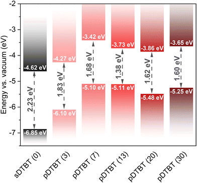
The optical band gaps (Eg) of the sublimed sDTBT and oCVD pDTBT thin films were determined from the UV/Vis/NIR absorption spectra using Tauc plots (Fig. S2, ESI†). Irrespective of the oxidant-to-monomer ratio, all the oCVD pDTBT thin films exhibit a band gap significantly lower than that of the starting DTBT monomer (Fig. 7 and Table S2, ESI†). Indeed, upon polymerisation, the valence band maxima (VBM), estimated from the valence band edge region of the XPS spectra (Fig. S3, ESI†), are shifted to higher values (Table S2, ESI†). This observation, consistent with the expansion of π-electronic system known to raise the energy of the highest occupied molecular orbital (HOMO), is responsible for the narrowing of the band gap to values as low as 1.38 eV for pDTBT (13) (Fig. 7).
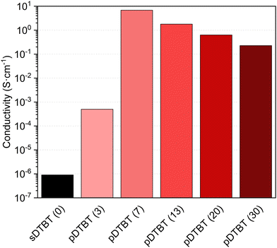
The current–voltage (I(V)) characteristics of the sDTBT (0) and oCVD pDTBT thin films deposited onto chips patterned with interdigitated electrodes revealed an ohmic behaviour. As expected, the polymerization of the DTBT upon reaction with FeCl3 induces a strong increase of the electrical conductivity from below 1 × 10⁻⁶ S cm−1 for sDTBT (0) to 5 × 10⁻⁴ S cm−1 for pDTBT (3) (Fig. 8). The conductivity of the oCVD pDTBT thin films is shown to be strongly dependent on the oxidant-to-monomer ratio with the maximum conductivity measured for pDTBT (7), 7 S cm−1. Increase of the oxidant-to-monomer ratio beyond 3 yields a progressive decrease of the conductivity to 1.8 S cm−1 and 0.2 S cm−1 for pDTBT (13) and pDTBT (30), respectively. Such a trend is consistent with the UV/Vis/NIR (Fig. 2b) and LDI-HRMS (Fig. 4) observations that indicate a lower degree of polymerization, likely due to chlorination of terminal thienyl groups, at the highest oxidant-to-monomer ratios investigated, i.e. pDTBT (20) and pDTBT (30). In addition, chlorination of the polymer chains (Fig. 3 and 5) reduces π–π stacking,45 contributing to lowering conductivity. Moreover, the inclusion of a large amount of non-conductive FeCl3 and FeCl3 by-products in the oCVD pDTBT thin films produced from the highest oxidant-to-monomer ratios are expected to negatively impact conductivity.37 Post-deposition rinsing with methanol or acids can remove both residual oxidants and unreacted monomers in oCVD thin films and therefore improve their electrical properties.29,32 Another potential improvement may involve the use of liquid oxidants, such as antimony pentachloride (SbCl5),38,39 in replacement of solid oxidants like FeCl3 whose by-products are well known to remain in the oCVD thin films.37
The hole mobility in the oCVD pDTBT thin films was evaluated by Hall effect measurements. Satisfactorily, the hole mobility in pDTBT (13), i.e. 4.0 cm2 V−1 s−1, surpasses those of previously reported benzothiadiazole–thiophene conjugated polymers.8,20–22 Such an improvement is attributed to the absence of side chains in the benzothiadiazole–thiophene conjugated polymers synthesized via oCVD. Indeed, previous works have highlighted the significance of side chains on the charge carrier mobility of conjugated polymers,46–49 including benzothiadiazole–thiophene conjugated polymers.20 Charge carrier mobility was notably reported to be directly proportional to the square of the interchain charge transfer integral.46–49 Reduced π–π stacking distances in conjugated polymers result in increased interchain charge transfer integrals, thereby leading to higher carrier mobilities and enhanced electrical conductivities.46 For the benzothiadiazole–thiophene conjugated polymers synthesized from solution-based methods (via Sonogashira or Stille cross-coupling polymerization),20,21 short side chains induce poor solubility and strong aggregation of the conjugated polymers in the solution phase, hindering the formation uniform and continuous thin films. On the other hand, long and bulky side chains used to prevent aggregation of the polymer chains in the solution phase, do not enable strong intermolecular interactions between the polymer chains in the solid state. Therefore, the highest hole mobilities were obtained for benzothiadiazole–thiophene conjugated polymers composed of benzothiadiazole and thiophene units substituted with octyl and octyloxy (0.670 cm2 V−1 s−1),8 nonyltridecyl (0.252 cm2 V−1 s−1),20 dodecyl (0.500 cm2 V−1 s−1)21 or octyldodecyl side chains (0.360 cm2 V−1 s−1).22 In a similar fashion, polymers of benzothiadiazole with thieno[3,2-b]thiophene bearing nonyl side chains17 or indacenodithiophene bearing dodecyl24 or hexadecyl side chains23 exhibit hole mobility as high as 0.100 cm2 V−1 s−1 and 2.630 cm2 V−1 s−1, respectively.
Although simple linear alkyl side chains are reported to increase the packing ability and the charge transport characteristics when compared to bulkier side chains,50–52 the integration of side chains by nature weakens intermolecular packing and charge mobility. Operating in the vapor phase for the simultaneous synthesis and deposition of conjugated polymers suppresses the need for a trade-off between the solubility of the polymer chains and their aggregation or π–π stacking in the solid state.31,35,36 The absence of the need for solubilizing groups in oCVD was previously exploited to enhance the sensing35 and catalytic properties36 of porphyrin-based conjugated polymer thin films. In the present work, the suppression of side chains resulted in the high hole mobility, i.e. 4.0 cm2 V−1 s−1, of the benzothiadiazole-based conjugated polymer.
The X-ray diffraction (XRD) pattern of the oCVD pDTBT (13) coating (Fig. 9) features a diffraction peak at 26.48° corresponding to a face-on stacking orientation (0k0) with a lamellar d-spacing of 3.4 Å. Interestingly, the π–π stacking distance of the oCVD pDBTB (13) coating (d = 3.4 Å) was significantly lower than the one reported for poly(4,7-dithien-2-yl-2,1,3-benzothiadiazole) substituted with octyloxy side chains (d = 4.0 Å).53 Noteworthily, the π–π stacking distance of the oCVD pDBTB (13) coating is similar to the one reported for face-on stacked PEDOT thin films prepared by oCVD (d = 3.4 Å).32
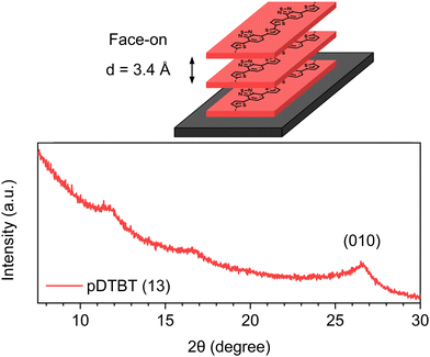 | ||
| Fig. 9 Schematic representation of the face-on stacking in the oCVD pDTBT thin films and X-ray diffraction pattern of the as-deposited oCVD pDTBT (13) coating. | ||
Interestingly, such a high hole mobility also suggests the formation of relatively high molecular weight benzothiadiazole-based conjugated polymers via oCVD. Even if the molecular weight cannot be determined due to the insolubility of the reported conjugated polymers, previous works have reported that high molecular weights are very important for the charge transport performances of benzothiadiazole-based conjugated polymers.20,23 It was notably reported that the hole mobility (0.252 cm2 V−1 s−1) of benzothiadiazole–thiophene conjugated polymers with higher molecular weights (40–60 kg mol−1) is higher than that of the conjugated polymers with lower molecular weights (20–30 kg mol−1).20 Similarly, an ultrahigh molecular weight, i.e. 1049.6 kg mol−1, is required for benzothiadiazole–indacenodithiophene conjugated polymers to reach hole mobility as high as 2.630 cm2 V−1 s−1.23
The ability to synthesize benzothiadiazole–oligothiophene D–A conjugated polymers and deposit them in the form smooth, dense and thickness-controlled thin films with a superior hole mobility constitutes a breakthrough in the field of benzothiadiazole-based conjugated polymers. The substrate independent oCVD method reported in this work can readily be implemented to other benzothiadiazole-based building blocks54 for engineering benzothiadiazole–oligothiophene D–A conjugated polymer thin films for OFETs,2 photovoltaics,4–6,10,12,14 electrochromic properties,25 and photocatalytic applications.11
Conclusions
oCVD provides a straightforward solventless, scalable and substrate independent approach for the facile synthesis, doping and deposition of low band gap benzothiadiazole–oligothiophene D–A conjugated polymers in the form of dense and low surface roughness thin films. Such features, notably low surface roughness with an arithmetic mean height close to 2 nm, are particularly interesting from the perspective of electronic and optoelectronic applications. Optimisation of the oxidant-to-monomer ratio enables enhancing the polymerization yield, doping and conductivity of the benzothiadiazole–oligothiophene conjugated polymer thin films. Taking advantage of the absence of the need for solubilizing groups in oCVD, none were attached to the benzothiadiazole or thienyl moieties, which allowed increasing the molecular packing of the polymer chains. Effective intramolecular and intermolecular π-electronic coupling allowed a remarkable improvement of the charge carrier transport properties with a hole mobility (4.0 cm2 V−1 s−1) that surpassed those previously reported for benzothiadiazole–thiophene conjugated polymers prepared by spin-coating, dip-coating and drop casting. This work highlighted that no more compromise needs to be made between solubility and high crystallinity when designing new benzothiadiazole–oligothiophene conjugated polymers and paves the way to the engineering of polymeric materials with improved performances.Experimental details
Oxidative chemical vapor deposition
The oCVD experiments were performed in a custom-built oCVD reactor equipped with two low temperature evaporators (Scheme S1, ESI†). The evaporators were loaded with ca. 8.8 mg of 4,7-dithien-2-yl-2,1,3-benzothiadiazole (DTBT) and ca. 161 mg of iron(III) chloride (FeCl3). DTBT was synthesized according to a previously described method.11 FeCl3 (97%) was purchased from Sigma-Aldrich and used without purification. The DTBT evaporator temperature was kept at 105 °C, while the oxidant's evaporator temperature was varied from 110 °C to 170 °C to sublime FeCl3 at different rates, as confirmed by weight measurements, and investigate oxidant-to-monomer molar ratio ranging from 3 to 30 (Table S1, ESI†). The oCVD reactor was fed with argon and maintained at a pressure of 10−3 mbar for all the duration of the oCVD reaction, which was set to 30 min. Borosilicate microscope glass slides (Menzel-Gläser), silicon wafers (Siltronix) and chips patterned with interdigitated gold electrodes were used as substrates.Thin film characterization
UV-Vis-NIR spectra of the sublimed and oCVD thin films deposited on borosilicate microscope glass slides were recorded using a PerkinElmer Lambda 1050 spectrophotometer, in the transmission (T) mode, in the 400–2000 nm wavelength region. The absorbance (A) was calculated using the equation A = −log(T). The direct band gaps (Eg) were evaluated from the Tauc plot, i.e. (αhν)2 plotted as a function of photon energy (hν). The direct band gaps were determined from the extrapolation of the linear fit of the leading edges of the spectra to the baseline. LDI-HRMS measurements were performed using an AP-MALDI UHR ion source (MassTech, Inc.) coupled to an LTQ/Orbitrap Elite (ThermoScientific). The measurements were performed on silicon wafers coated either with the sublimed DTBT monomer or the oCVD thin films and directly placed on the sample holder without MALDI matrix deposition. XPS analyses were performed on a Thermofisher Nexsa G2 instrument using a monochromatic Al Kα X-ray source (E = 1486.6 eV) with a spot size of 400 μm. Charge calibration was accomplished by fixing the binding energy of carbon (C 1s) to 285.0 eV. SEM top-view and cross-sectional images were obtained using a Hitachi SU-70 FE-SEM. To avoid distortions due to charge effect, the samples were coated with a 5-nm platinum layer before the SEM observations. The thickness of the thin films was evaluated from cross-sectional SEM observations as well as by using an Alpha step d-500 profilometer from KLATencor. An AFM MFP3D Infinity (Oxford Instruments) was used for the characterization of the surface morphology of the thin films. Due to the “soft” nature of the material, tapping mode was adopted. Topography images were acquired in air in tapping mode at scan rates of 1 Hz and a resolution of 512 × 512 pixels2 over a 2 × 2 μm2. Semi-contact silicon AC160TS AFM tips (Olympus) with a cantilever spring constant of 26 N m−1 were used. Surface topography of the deposit was acquired by maintaining the cantilever first resonance amplitude constant via the feedback loop of the AFM acting in the piezo Z direction. Roughness parameter Sa is extracted from the topography images using MountainSPIP software (Digital Surf). The electrical conductivity was evaluated from the thin films deposited on chips patterned with interdigitated gold electrodes. The current–voltage scans were recorded using a two-point probe and the conductivity was evaluated using Ohm's law. The Hall effect was studied using an Ecopia HMS 3000 system (magnetic field: 0.5 T) for charge carrier concentration and mobility measurements. The electrical resistivity in the van der Pauw configuration was also determined using the same Hall effect system. The electrical resistivities measured by using the van der Pauw configuration on a sample area of 1 cm2 were in good agreement with the resistivity measured by using the two-point probe configuration. X-ray diffraction (XRD) analysis was performed in grazing incidence mode (0.5°) using a Bruker D8 Advance diffractometer operating at 40 kV and 40 mA with Cu Kα radiation (λ = 1.5406 Å).Author contributions
M. K. C.: conceptualization, synthesis, investigation, formal analysis; J. C.: investigation, formal analysis, writing – original draft; K. K.: synthesis, investigation, formal analysis, writing – review and editing; M. G.: synthesis; W. L.: investigation; G. F.: investigation; P. G.: investigation, formal analysis, writing – original draft; J. G.: investigation, formal analysis; K. B.: investigation, writing – review and editing; N. D. B.: conceptualization, methodology, investigation, formal analysis, funding acquisition, writing – original draft, writing – review and editing.Data availability
The data supporting this article have been included as part of the ESI.†Conflicts of interest
There are no conflicts to declare.Acknowledgements
This project has received funding from the European Research Council (ERC) under the European Union's Horizon 2020 research and innovation program (grant agreement No. 865985). This project has also received funding from the European Union's Horizon 2020 research and innovation programme under the Marie Sklodowska-Curie grant agreement No. 101031568. K. K. expresses his gratitude to the National Science Centre of Poland for financial support through grant No. 2019/32/C/ST5/00179. B. Marcolini, C. Vergne and Y. Fleming from LIST are acknowledged for data collection and insightful discussions.References
- I. Bala, R. A. K. Yadav, M. Devi, J. De, N. Singh, K. Kailasam, J. Jayakumar, J.-H. Jou, C.-H. Cheng and S. K. Pal, J. Mater. Chem. C, 2020, 8, 17009–17015 RSC.
- J. Cameron, L. Nanson, N. Blouin, N. J. Findlay, A. R. Inigo and P. J. Skabara, Org. Electron., 2017, 49, 400–405 CrossRef CAS.
- M. Axelsson, C. F. N. Marchiori, P. Huang, C. M. Araujo and H. Tian, J. Am. Chem. Soc., 2021, 143, 21229–21233 CrossRef CAS PubMed.
- D. Keles, M. C. Erer, E. Bolayir, S. C. Cevher, G. Hizalan, L. Toppare and A. Cirpan, Renew. Energy, 2019, 139, 1184–1193 CrossRef CAS.
- P. Cong, Z. Wang, Y. Geng, Y. Meng, C. Meng, L. Chen, A. Tang and E. Zhou, Nano Energy, 2023, 105, 108017 CrossRef CAS.
- C. Wang, D. Xia, F. Yang, J. Li, Y. Wu and W. Li, ACS Appl. Polym. Mater., 2021, 3, 4645–4650 CrossRef CAS.
- Y. Wang and T. Michinobu, J. Mater. Chem. C, 2016, 4, 6200–6214 RSC.
- B. Fu, J. Baltazar, Z. Hu, A.-T. Chien, S. Kumar, C. L. Henderson, D. M. Collard and E. Reichmanis, Chem. Mater., 2012, 24, 4123–4133 CrossRef CAS.
- P. M. Dicarmine, T. B. Schon, T. M. McCormick, P. P. Klein and D. S. Seferos, J. Phys. Chem. C, 2014, 118, 8295–8307 CrossRef CAS.
- F. Liang, J. Lu, J. Ding, R. Movileanu and Y. Tao, Macromolecules, 2009, 42, 6107–6114 CrossRef CAS.
- R. Gańczarczyk, R. Rybakiewicz-Sekita, M. Gryszel, J. Drapała, M. Zagórska and E. D. Głowacki, Adv. Mater. Interfaces, 2023, 10, 2300270 CrossRef.
- A. A. B. Alghamdi, D. C. Watters, H. Yi, S. Al-Faifi, M. S. Almeataq, D. Coles, J. Kingsley, D. G. Lidzey and A. Iraqi, J. Mater. Chem. A, 2013, 1, 5165–5171 RSC.
- P. Ledwon, N. Thomson, E. Angioni, N. J. Findlay, P. J. Skabara and W. Domagala, RSC Adv., 2015, 5, 77303–77315 RSC.
- Q. Nie, A. Tang, Q. Guo and E. Zhou, Nano Energy, 2021, 87, 106174 CrossRef CAS.
- A. F. Paterson, S. Singh, K. J. Fallon, T. Hodsden, Y. Han, B. C. Schroeder, H. Bronstein, M. Heeney, I. McCulloch and T. D. Anthopoulos, Adv. Mater., 2018, 30, 1801079 CrossRef PubMed.
- A. Sanzone, A. Calascibetta, M. Monti, S. Mattiello, M. Sassi, F. Corsini, G. Griffini, M. Sommer and L. Beverina, ACS Macro Lett., 2020, 9, 1167–1171 CrossRef CAS PubMed.
- B. Amna, R. Isci, H. M. Siddiqi, L. A. Majewski, S. Faraji and T. Ozturk, J. Mater. Chem. C, 2022, 10, 8254–8265 RSC.
- J. Jiang and S. Yoon, Sci. Rep., 2018, 8, 13243 CrossRef PubMed.
- M. Li, C. An, W. Pisula and K. Müllen, Acc. Chem. Res., 2018, 51, 1196–1205 CrossRef CAS PubMed.
- X. Huang, S. Fu, C. Lin, Y. Lu, M. Wang, P. Zhang, C. Huang, Z. Li, Z. Liao, Y. Zou, J. Li, S. Zhou, M. Helm, P. St. Petkov, T. Heine, M. Bonn, H. I. Wang, X. Feng and R. Dong, J. Am. Chem. Soc., 2023, 145, 2430–2438 CrossRef CAS PubMed.
- M. Comí, D. Patra, R. Yang, Z. Chen, A. Harbuzaru, Y. Wubulikasimu, S. Banerjee, R. Ponce Ortiz, Y. Liu and M. Al-Hashimi, J. Mater. Chem. C, 2021, 9, 5113–5123 RSC.
- W. Sun, Y. Chen, X. Liang, L. Tan, Z. Liu, Z. Cai, L. Dong and L. Wang, New J. Chem., 2018, 42, 15372–15378 RSC.
- B. Zhao, D. Pei, Y. Jiang, Z. Wang, C. An, Y. Deng, Z. Ma, Y. Han and Y. Geng, Macromolecules, 2021, 54, 9896–9905 CrossRef CAS.
- D. Adamczak, A. Perinot, H. Komber, A. Illy, S. Hultmark, B. Passarella, W. L. Tan, S. Hutsch, D. Becker-Koch, C. Rapley, A. D. Scaccabarozzi, M. Heeney, Y. Vaynzof, F. Ortmann, C. R. McNeill, C. Müller, M. Caironi and M. Sommer, J. Mater. Chem. C, 2021, 9, 4597–4606 RSC.
- O. Atwani, C. Baristiran, A. Erden and G. Sonmez, Synth. Met., 2008, 158, 83–89 CrossRef CAS.
- C. Kitamura, S. Tanaka and Y. Yamashita, Chem. Mater., 1996, 8, 570–578 CrossRef CAS.
- A. Kafizas, C. J. Carmalt and I. P. Parkin, Coord. Chem. Rev., 2013, 257, 2073–2119 CrossRef CAS.
- M. Wang, X. Wang, P. Moni, A. Liu, D. H. Kim, W. J. Jo, H. Sojoudi and K. K. Gleason, Adv. Mater., 2017, 29, 1604606 CrossRef PubMed.
- M. Heydari Gharahcheshmeh and K. K. Gleason, Adv. Mater. Interfaces, 2019, 6, 1801564 CrossRef.
- H. Goktas, X. Wang, N. D. Boscher, S. Torosian and K. K. Gleason, J. Mater. Chem. C, 2016, 4, 3403–3414 RSC.
- G. Bengasi, J. S. Desport, K. Baba, J. P. Cosas Fernandes, O. De Castro, K. Heinze and N. D. Boscher, RSC Adv., 2020, 10, 7048–7057 RSC.
- X. Wang, X. Zhang, L. Sun, D. Lee, S. Lee, M. Wang, J. Zhao, Y. Shao-Horn, M. Dincă, T. Palacios and K. K. Gleason, Sci. Adv., 2018, 4, eaat5780 CrossRef CAS PubMed.
- J. F. Jr. Ponder, S. A. Gregory, A. Atassi, A. K. Menon, A. W. Lang, L. R. Savagian, J. R. Reynolds and S. K. Yee, J. Am. Chem. Soc., 2022, 144, 1351–1360 CrossRef PubMed.
- M. K. Charyton, T. Reiker, K. Kotwica, M. Góra, H. Zacharias and N. D. Boscher, Mater. Adv., 2023, 4, 2625–2635 RSC.
- G. Bengasi, R. Meunier-Prest, K. Baba, A. Kumar, A. L. Pellegrino, N. D. Boscher and M. Bouvet, Adv. Electron. Mater., 2020, 6, 2000812 CrossRef CAS.
- A. M. Huerta-Flores, G. Bengasi, K. Baba and N. D. Boscher, ACS Appl. Energy Mater., 2020, 3, 9848–9855 CrossRef CAS.
- K. Baba, G. Bengasi, D. El Assad, P. Grysan, E. Lentzen, K. Heinze, G. Frache and N. D. Boscher, Eur. J. Org. Chem., 2019, 1–9 Search PubMed.
- K. Chowdhury, S. K. Behura, M. Rahimi and M. Heydari Gharahcheshmeh, ACS Appl. Energy Mater., 2024, 7, 1068–1079 CrossRef CAS.
- S. I. G. P. Mohamed, S. Namvar, T. Zhang, H. Shahbazi, Z. Jiang, A. M. Rappe, A. Salehi-Khojin and S. Nejati, Adv. Mater., 2024, 36, 2309302 CrossRef CAS PubMed.
- S. Nejati, T. E. Minford, Y. Y. Smolin and K. K. S. Lau, ACS Nano, 2014, 8, 5413–5422 CrossRef CAS PubMed.
- M. Scarongella, A. Laktionov, U. Rothlisberger and N. Banerji, J. Mater. Chem. C, 2013, 1, 2308–2319 RSC.
- J. Yamamoto and Y. Furukawa, J. Phys. Chem. B, 2015, 119, 4788–4794 CrossRef CAS PubMed.
- A. L. Pellegrino, G. Bengasi, K. Baba, D. Cardenas-Morcoso, D. Bansal, G. Malandrino and N. D. Boscher, Adv. Mater. Interfaces, 2023, 10, 2202237 CrossRef CAS.
- D. Bansal, D. Cardenas-Morcoso and N. D. Boscher, J. Mater. Chem. A, 2023, 11, 5188–5198 RSC.
- H. Bin, I. Angunawela, R. Ma, A. Nallapaneni, C. Zhu, P. J. Leenaers, B. W. H. Saes, M. M. Wienk, H. Yan, H. Ade and R. A. J. Janssen, J. Mater. Chem. C, 2020, 8, 15426–15435 RSC.
- M. Heydari Gharahcheshmeh and K. K. Gleason, Mater. Today Adv., 2020, 8, 100086 CrossRef.
- M. Heydari Gharahcheshmeh, M. T. Robinson, E. F. Gleason and K. K. Gleason, Adv. Funct. Mater., 2021, 31, 2008712 CrossRef CAS.
- V. Coropceanu, J. Cornil, D. A. da Silva Filho, Y. Olivier, R. Silbey and J.-L. Brédas, Chem. Rev., 2007, 107, 926–952 CrossRef CAS PubMed.
- Y.-K. Lan and C.-I. Huang, J. Phys. Chem. B, 2008, 112, 14857–14862 CrossRef CAS PubMed.
- Y. Lin, Q. He, F. Zhao, L. Huo, J. Mai, X. Lu, C.-J. Su, T. Li, J. Wang, J. Zhu, Y. Sun, C. Wang and X. Zhan, J. Am. Chem. Soc., 2016, 138, 2973–2976 CrossRef CAS PubMed.
- X. Song, N. Gasparini, M. M. Nahid, H. Chen, S. M. Macphee, W. Zhang, V. Norman, C. Zhu, D. Bryant, H. Ade, I. McCulloch and D. Baran, Adv. Funct. Mater., 2018, 28, 1802895 CrossRef.
- D. Yang, Y. Wang, T. Sano, F. Gao, H. Sasabe and J. Kido, J. Mater. Chem. A, 2018, 6, 13918–13924 RSC.
- H. J. Song, M. Goh, K. H. Choi, S. Lee, D. K. Moon and G. J. Shin, J. Ind. Eng. Chem., 2015, 23, 338–343 CrossRef CAS.
- J. Liu, W. Li, K. Xian, Z. Liu, Y. Li, X. Yao, L. Ye, Y. Zhao and Z. Fei, Chin. J. Chem., 2023, 41, 2525–2530 CrossRef CAS.
Footnote |
| † Electronic supplementary information (ESI) available. See DOI: https://doi.org/10.1039/d4tc01437e |
| This journal is © The Royal Society of Chemistry 2024 |


