
Research progress on layered metal oxide electrocatalysts for an efficient oxygen evolution reaction
Lei
Li
,
Yaoda
Liu
 ,
Ya
Chen
,
Wenfang
Zhai
and
Zhengfei
Dai
*
,
Ya
Chen
,
Wenfang
Zhai
and
Zhengfei
Dai
*
State Key Laboratory for Mechanical Behavior of Materials, Xi'an Jiaotong University, Xi'an 710049, China. E-mail: sensdai@mail.xjtu.edu.cn
First published on 30th April 2024
Abstract
Hydrogen, highly valued for its pristine cleanliness and remarkable efficiency as an emerging energy source, is anticipated to ascend to a preeminent status within the forthcoming energy landscape. Electrocatalytic water splitting is considered a pivotal, eco-friendly, and sustainable strategy for hydrogen production. The substantial energy consumption stemming from oxygen evolution side reactions significantly impedes the commercial viability of water electrolysis. Consequently, the pursuit of a cost-effective and efficacious oxygen evolution reaction (OER) catalyst stands as an imperative strategy for realizing hydrogen production via water electrolysis. Layered metal oxides, owing to their robust anisotropic properties, versatile adjustability, and extensive surface area, have emerged as suitable candidates for OER catalysts. However, owing to the distinctive attributes of layered metal oxides, ongoing investigations into these materials are slightly fragmented, lacking universal consensus. This article comprehensively surveys the recent advancements in layered metal oxide–based OER catalysts, categorized into single metal oxides, alkali cobalt oxides, perovskites, and miscellaneous metal oxides. Initially, the main OER intermediate reaction steps of layered metal oxides are scrutinized. Subsequently, the design, mechanism, and application of several pivotal layered metal oxides in the OER are systematically delineated. Finally, a summary is provided, alongside the proposal of future research trajectories and challenges encountered by layered metal oxides, with the aspiration that this paper may serve as a valuable reference for scholars in the field.
1. Introduction
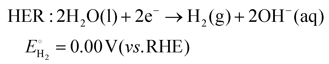
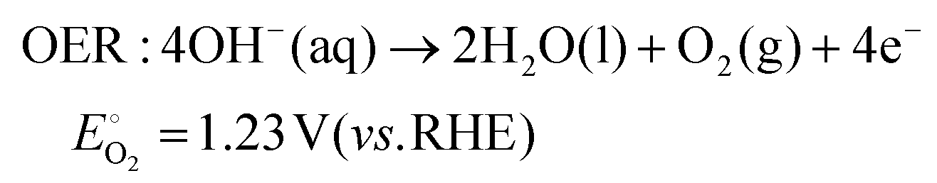
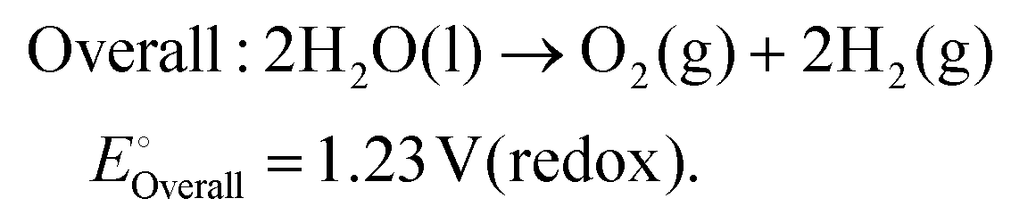
As technological advancements burgeon and societal evolution unfolds, the echelons of global industrialization ascend ever higher. The trajectory of industrial advancement remains inexorably intertwined with humanity's exploitation and utilization of the natural world, leading to increasingly prominent damage to the natural environment. Presently, the main energy consumption stems predominantly from non-renewable resources, including coal mines, oil, and natural gas, notwithstanding the growing integration of eco-friendly alternatives such as wind, solar, and tidal energies.1–4 Nevertheless, they are often limited by external factors such as natural climate and cannot be utilized for a long time, and their contribution to the overall energy framework remains relatively minimal.5,6 Therefore, there emerges an imperative need to develop a novel sustainable green energy, supplanting fossil fuels, thus protecting the earth's environment. Hydrogen energy, as a new type of green energy, has a wide range of sources, high heat of combustion value, clean and pollution-free nature, and an intrinsic capacity for energy storage, which enable it to play a pivotal role in the prospective energy landscape.7,8 Currently, two primary avenues exist for hydrogen production: one involves harnessing fossil fuels to generate hydrogen, such as gas reforming, oil refining, coal gasification, and alcohol cracking, whereas the other entails green hydrogen synthesis via the electrolysis of water using electricity or photoinduced decomposition.9–14 Conversely, electrolytic water splitting for hydrogen generation stands out for its simplicity, diversity in electrical energy sources, and myriad benefits such as heightened product purity and environmental friendliness, thus positioning itself as a promising avenue for hydrogen production.15–17In the process of water electrolysis, two pivotal half-reactions unfold at the anode and cathode: the two-electron hydrogen evolution reaction (HER) and four-electron oxygen evolution reaction (OER).18,19 Utilizing alkaline electrolytes as a case study,20 the reaction equations are as follows:
 | (1) |
 | (2) |
 | (3) |
Theoretically, water decomposes into H2 and O2 and requires a voltage of 1.23 V between the cathode and anode to facilitate the transfer of 4e−.21 However, owing to the intricate nature of intermediate reactions, the conversion process of intermediary products must surmount certain potential barriers to propel the progression of both cathodic and anodic reactions.22 To mitigate the Gibbs free energy of the reaction process in kinetics, thereby alleviating the overpotential of the reaction, the utilization of catalysts has surfaced. Given the involvement of four-electron transfers in the OER process, it is widely acknowledged that OER proceeds at a significantly slower pace than that of the HER in kinetics.23,24 Hence, the development of efficient OER catalysts stands as pivotal in enhancing the overall water decomposition efficiency. In the nascent stages of research, noble metal–based catalysts attracted extensive attention due to their remarkable activity and stability. Notably, IrO2 and RuO2 have found widespread application in OER processes and serve as primary commercial catalytic materials.25,26 Consequently, researchers are developing novel OER catalysts from three perspectives: (1) to reduce dependence on precious metals, (2) to develop precious metal–based compounds, and (3) to develop non-precious metal–based materials.27–29 Since the electrolysis of water for hydrogen production has entered the field of research, a large number of metal-based OER catalysts have been developed, spanning metal oxides, sulfur compounds, nitrides, phosphides, and beyond.30–33 Two-dimensional materials including metal halides, metal oxides, metal hydroxides have attracted much attention due to their significant advantages in exposing multiple active sites.34–36
This article focuses predominantly on summary OER catalysts grounded in layered metal oxides (LMOs). Layered metal oxides represent a distinctive category of solid materials characterized by pronounced anisotropy across their basal and edge planes, thereby conferring upon them unexpected chemical and physical attributes.37,38 Moreover, LMOs present a capacity for undergoing low-temperature chemical transformations devoid of compromising the integrity of covalent bonds within the layers.39 These metal oxides may assume a morphology comprising a few or single layers crafted through specific methodologies, or they may show as stacks of electrically neutral metal oxide layers. However, more commonly, they coexist with charged layers interwoven with cations or anions, or their metal oxide sheets alternate with the middle layer of covalent bonds.40–43 LMOs boast several advantageous traits: (i) thermodynamic stability and difficulty in breaking covalent bonds within the layer.44,45 (ii) In most cases, in aqueous and highly oxidizing environments, metal oxides readily transition into corresponding metal (oxygen) hydroxides, which serve as genuine OER active species.46 (iii) LMOs exhibit compositional flexibility and adaptable intercalation groups, thereby engendering a diverse coordination environment at their active sites, thereby affording excellent OER activity and stability.40,47,48
In this comprehensive review, we scrutinize the recent strides in researching the materials and structures of LMOs as OER catalysts. Initially, we delineate three distinct evolutionary mechanisms operative in the OER process. Subsequently, we provide a concise overview of several conventional and newly discovered layered metal oxide OER catalysts, encompassing single metal oxides, alkali cobalt oxides, perovskites, V2O5·nH2O, cobalt phyllosilicate, brownmillerite, and weberite. On this basis, we expound upon methodologies for modifying layered metal oxides, elucidate key factors contributing to enhancing their activity or stability, and point out the gaps that still exist in research. Finally, we summarize the relationship between the structures of layered metal oxides, the triggering of OER mechanisms, and the factors enhancing electrocatalytic performance. Moreover, we outline the future research directions and challenges confronting layered metal oxides (Fig. 1). This endeavor aims to furnish valuable insights into the application of layered metal oxides in the OER domain, thereby accelerating the commercialization of hydrogen production through water electrolysis.
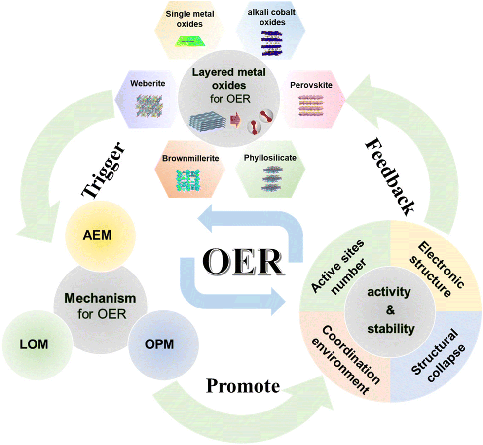 | ||
| Fig. 1 Schematic diagram of the oxygen evolution reaction process of LMOs from basic materials and reaction mechanisms to OER performance. (AEM: adsorbate evolution mechanism; LOM: lattice oxygen evolution mechanism; OPM: oxide path mechanism.) Adapted with permission from ref. 73. Copyright 2020, the Royal Society of Chemistry. Adapted with permission from ref. 66. Copyright 2021, Elsevier. Adapted with permission from ref. 93. Copyright 2022, American Chemical Society. Adapted with permission from ref. 43. Copyright 2017, WILEY. Adapted with permission from ref. 106. Copyright 2022, American Chemical Society. Adapted with permission from ref. 107. Copyright 2023, Springer Nature. | ||
2. Hydrogen economy
With rapid development of global industries, nations are strategically elevating hydrogen energy to a paramount position on their agendas. The United States was the first to propose the concept of using hydrogen energy as a basic energy carrier to build a future energy society. As early as 2001, the US Department of Energy issued the “2030 Vision for America's Transition to a Hydrogen Economy”, which pointed out that hydrogen will replace fossil fuels as the main energy source supporting the global economy in the future, forming a market operation system based on the production, storage, transportation, and application of hydrogen energy, known as the “Hydrogen Economy”.49 Moreover, numerous nations including Germany and China have crafted extensive blueprints for the long-term utilization of hydrogen energy technology, positioning it strategically within their agendas. Electrolytic hydrogen production technology, leveraging renewable green energy sources, stands poised to effectively mitigate intermittent energy consumption challenges posed by solar and wind energy. This technology assumes a pivotal role in the storage, conversion, and optimal utilization of clean energy resources.50 Nonetheless, the issue of hydrogen persistent production costs remains a central issue thwarting the widespread commercialization of electrolytic water hydrogen production technology. In terms of green hydrogen production capacity, the European Union aims to establish an electrolysis system of 40–60 GW by 2030. The relevant strategy also points out the specific goal of achieving a hydrogen production capacity of 1 million t·a−1 by 2030. The Netherlands also pointed out that, based on the existing 10 MW electrolytic cell system, a 3–4 GW green hydrogen production plant will be further constructed before 2030.51,52 Nevertheless, to realize sustained production of high-quality and low-cost hydrogen, resolving the issue of energy consumption in the anode's OER process is imperative. Therefore, designing and fabricating highly active and enduringly stable catalysts emerge as pressing imperatives in attaining the envisioned hydrogen energy landscape.3. OER mechanisms for transition metal oxide electrocatalysts
Mastering the relationship between catalyst performance and reaction mechanism is crucial for guiding catalyst design. Currently, three distinguished evolutionary mechanisms for OER catalytic processes have been acknowledged.53–55 The most common reaction mechanisms are as follows: (i) adsorbate evolution mechanism (AEM), (ii) lattice oxygen-evolution mechanism (LOM), and (iii) the novel mechanism discovered in recent years: oxide path mechanism (OPM). A fundamental relationship exists between the catalytic reaction mechanism and the catalytic active site. Moreover, various electrolytes induce disparities in the initial reactants, thereby exerting a discernible influence on the reaction process. In alkaline solutions, a substantial concentration of ionized OH− facilitates the onset of the OER process. Within this context, a concise overview of the reaction process alongside illustrative examples is presented to elucidate the diverse mechanisms operative in alkaline electrolyte environments.3.1 Adsorbate evolution mechanism (AEM)
As shown in Fig. 2a, during the OER process, the AEM pathway involves four electron–proton transfer steps occurring at the metal-ion centers exposed to the catalyst surface.56 Initially, the metal active site combines with the OH− ion in the electrolytes and evolves into *OH attached to the metal (where * denotes the metal site). Subsequently, the intermediate *OH reacts with OH− in the electrolyte to form an *O intermediate via deprotonation. Following this, an another OH− ion from electrolytes combines with the *O intermediate to form the intermediate *OOH. Further deprotonation evolves into O2 molecules, which then escape from the metal site, leaving a vacancy that is then replenished with OH− in the electrolyte solution.57 Within this cycle, the OER process catalyzed by the AEM exhibits a circular nature, yielding the intermediates *OH, *O, and *OOH.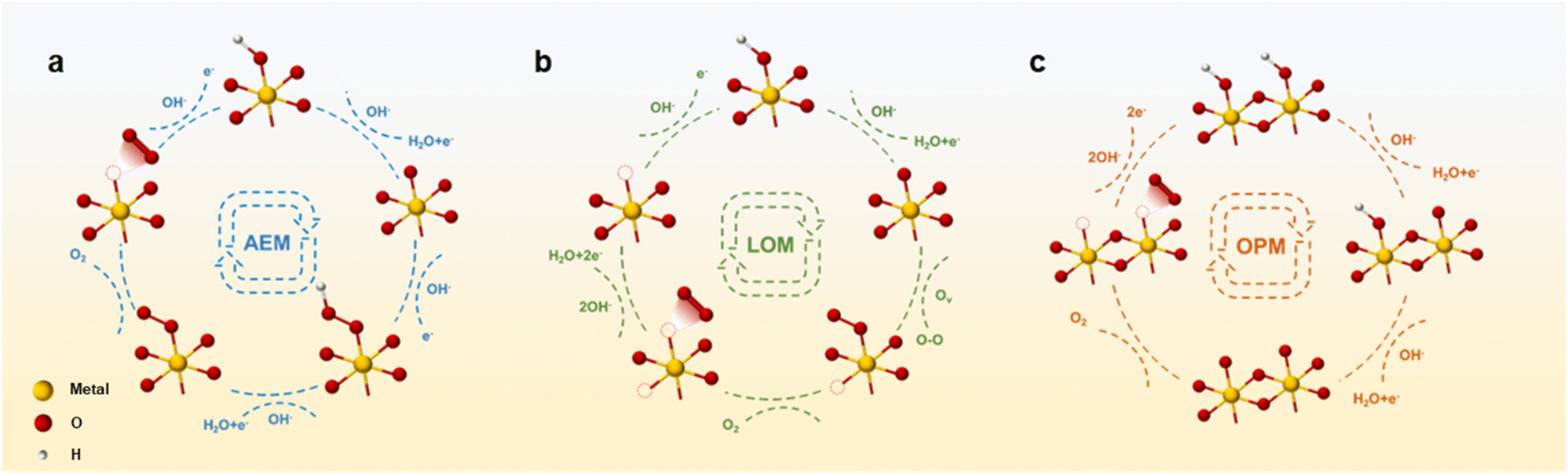 | ||
| Fig. 2 Schematic diagram of (a) AEM, (b) LOM, and (c) OPM in alkaline OER process. | ||
Ideally, the catalytic process following AEM should have an equal Gibbs free energy at each reaction step, totaling 1.23 eV.58 However, a fixed scaling relationship exists between the binding energies resulting from *OH deprotonation and *OOH formation. Therefore, there exists an almost constant energy difference ΔG*OOH − ΔG*OH = 3.2 eV. Consequently, a deviation arises between the actual and theoretical free energies, resulting in a minimum overpotential range of 0.2–0.4 V for the AEM process.59,60 The variance in Gibbs free energy at each step leads to the presence of a rate-determining step (RDS) within the AEM process, typically associated with either *OH deprotonation or *OOH formation, thereby influencing the oxygen evolution reaction (OER) potential.61 Meanwhile, owing to the constant energy difference of ΔG*OOH − ΔG*OH = 3.2 eV, the OER overpotential is described by the (ΔG*O − ΔG*OH) value as the OER activity descriptor. Typically, when the (ΔG*O − ΔG*OH) value is around 1.6 eV, it indicates an optimal oxygen binding strength conducive to optimal OER activity. Below this value, the binding strength of oxygen will be too strong, hindering the subsequent formation of *OOH, whereas surpassing this threshold renders oxygen binding strength too weak, impeding *OH deprotonation.62
Subsequently, Hammer and Nørskov proposed the d-band theory based on first-principles calculations, utilizing the d-band center as a single parameter to evaluate the effect of clean metal surfaces on the catalytic activity of metal groups.63 Based on their research, the d-band center exhibits a close correlation with the stability of surface atoms/molecules and the transition state energy of surface processes. The shift of the d-band center of the active site transition metal towards the Fermi level serves to enhance the adsorption of intermediates. Conversely, a greater distance of the d-band center from the Fermi level results in the weakening of the adsorption of intermediates.64,65 Inspired by the d-band center theory, Dai et al. discovered that the intrinsic activity of layered alkali metal oxides can be regulated by adjusting the CoO6 octahedron, which is shared by the inner edge of the layer and spacing/strain between CoO2 layers. The authors investigated the modulation of the OER activity of Na0.7CoO2 layered oxides by Ag, Cu, and Ce doping and cation removal. The results indicate that the lattice strain introduced by the cation removal process leads to a positive shift in the d-band center of the surface Co atom, thereby modulating ΔG*OH and facilitating the deprotonation process towards a moderate free energy, consequently lowering the energy barrier during the reaction process.66
3.2 Lattice oxygen-evolution mechanism (LOM)
Through extensive investigation into the OER mechanism, researchers have uncovered that oxygen atoms constituting oxygen molecules may arise not only from water molecules but also from the lattice oxygen evolution of metal oxides (Fig. 2b).67 The electronic configuration of the active sites in such OER catalysts typically deviates from the d-band center state conducive to maintaining Gibbs free energy equilibrium in the AEM process. The sequential stages of the OER process diverge from those observed in the AEM. Initially, OH− in the electrolyte adsorbs on metal active sites, evolving into *OH. Go through the deprotonation step to form the intermediate *O. In contrast to the continuation of OH− adsorption to generate the *OOH intermediate in the AEM process, *O binds to lattice oxygen within the catalyst body, liberating it as O2. Due to the deficiency of lattice oxygen, oxygen vacancies are generated within the principal lattice structure of the catalyst.57 Subsequently, two distinct methods are employed to replenish oxygen vacancies. On the one hand, other oxygen atoms in the catalyst body diffuse to occupy vacancies, and on the other hand, defects are filled through OH− adsorption and deprotonation in the electrolyte. This particular OER mechanism is referred to as LOM due to its involvement of oxygen atoms within the catalyst body in addition to those present in the electrolyte solution. In addition, the LOM process bypasses the limitation of intermediate *OOH formation, thus, layered oxides based on LOM hold promise for achieving enhanced OER activity.68 However, attention to the pervasive issue of heavy metal leaching, commonly associated with LOM, proves challenging.69 For example, Ge et al. synthesized an excellent OER catalyst by loading single-atom Ir sites onto layered MnO2. More precisely, the introduction of single Ir atoms triggers the activation of lattice oxygen. Compared to the bulk-phase IrO2, the Ir–O bond length of the Ir single atom dispersed on the surface of MnO2 is shortened, which is more suitable for the chelation structure. Authors directly demonstrated that the LOM process on the isolated Ir site was opened through in situ methods. Therefore, it has better OER activity, which is more than 42 times that of industrial IrO2. Furthermore, the activation of local lattice oxygen mitigates significant ion migration during the OER process, thereby preventing catalyst structure degradation. As a result, the catalyst has a stability up to 650 hours.703.3 Oxide path mechanism (OPM)
Apart from the AEM and LOM processes, there exists the OPM characterized by OER activity and stability surpassing theoretical thresholds.40,71 The OPM pathway is different from other reaction processes in that one unit of the reaction process occurs simultaneously at two metal active sites, facilitating the direct coupling of O–O radicals. In the OER process driven by the OPM, only intermediates *O and *OH are generated, devoid of oxygen vacancy defects and reaction intermediates *OOH (Fig. 2c).53,55 The OPM process needs to work collaboratively through active metal sites at appropriate positions to deprotonate and trigger the coupling of *O and other *O radicals to generate O2. Therefore, stringent demand exists for the geometric arrangements of metal active sites. For example, Shigeo Mori et al. introduced a novel structure of perovskite CaCu3Fe4O12 (CCFO). Compared to the traditional ABO3-type perovskite, this structure not only stabilizes via covalent Fe–O–Cu bonds but also diverges from the conventional AEM pathway, embracing the OPM with bimetallic active sites. During the OER process, effective electron transfer to Fe ions occurs, facilitated by robust Fe–O covalent bonds, with the reaction proceeding via the oxidation–reduction of Fe4+/Fe5+ ions.72 Moreover, owing to the unique perovskite structure, the Fe–Fe atomic distance remains relatively short, naturally facilitating the operation of the OPM.4. Layered oxides for OER catalysts
4.1 Single metal oxides
Currently, two primary approaches exist for the modification of layered single metal oxide OER catalysts: (i) morphological regulation. Through specialized methods and conditions, conventional single metal oxides are transformed into two-dimensional layered structures, primarily aimed at enhancing surface exposure, augmenting active sites, and consequently, fostering heightened OER activity. (ii) Leveraging layered oxides as carriers facilitates the facile dispersion of precious metal units onto their surfaces, thereby diminishing the precious metal loading while ameliorating the electronic structure of metal sites, thus favoring the realization of excellent OER activity. Li et al. prepared ultra-thin single-layer or few-layer RuO2 nanosheets (RuO2 NSs) by a simple molten salt method using NaNO3 as a template at specific temperatures (Fig. 3a). The RuO2 NS surface has abundant Ru vacancies, significantly weakening the binding energy of *O, thereby reducing the energy barrier of the conversion process from *O to *OOH and improving OER performance. At a current density of 10 mA cm−2, the overpotential is extremely low at 199 mV. The excellent performance is attributed to the exposure of high surface area in layered structures and the influence of defect introduction on the electronic structure of active centers.73 Shao et al. reported the synthesis of pure-phase IrO2: 1T-phase IrO2 (1T-IrO2) achieved through a combination of mechanochemistry and heat treatment in a strongly alkaline medium. As shown in Fig. 3b and c, the SEM and TEM images reveal that the synthesized IrO2 possesses an ultra-thin layered structure. In addition, its atomic arrangement aligns with the crystal structure of 1T phase (Fig. 3d). IrO2 materials usually have three phase structures: 1T, 2H, and 3R. Unlike the two closely packed stacking arrangements of 2H and 3R, the 1T phase exhibits a distinctive layered structure characterized by AA stacking (Fig. 3e–g). Compared to IrO2 in the rutile phase, the special phase structure of 1T-IrO2 facilitates the generation of *OH species during the OER process, consequently enhancing the OER activity. At a constant current density of 10 mA cm−2, the overpotential is as low as 197 mV. Assembled in a proton exchange membrane device, it exhibits excellent stability for 126 hours at a high current density of 250 mA cm−2.74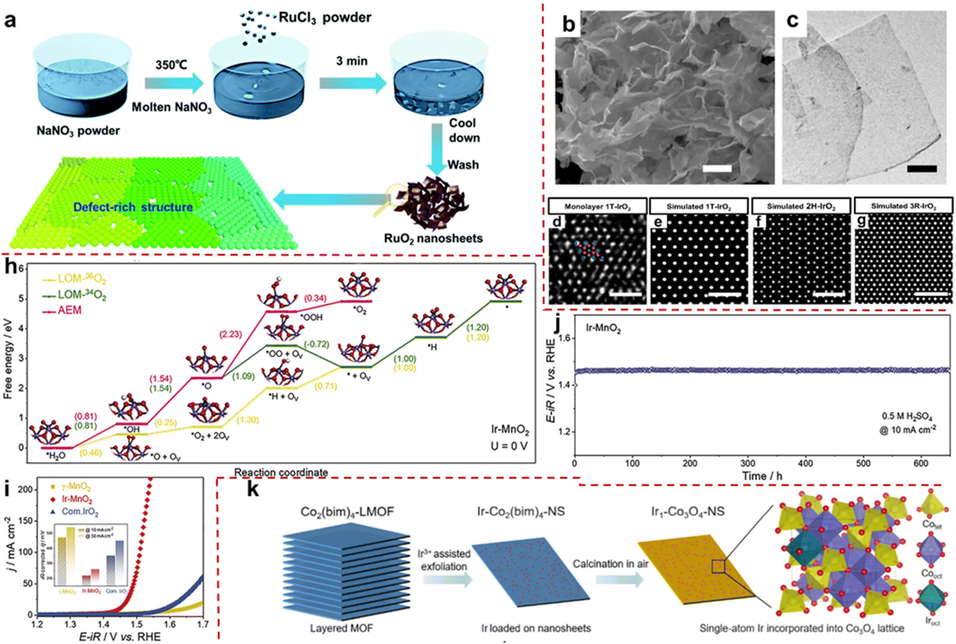 | ||
| Fig. 3 (a) Schematic route of the synthesis of the defect rich monolayer RuO2. Adapted with permission from ref. 73. Copyright 2020, the Royal Society of Chemistry. (b and c) SEM and TEM images of 1T-IrO2. (d) HAADF-STEM image of single-layer 1T-IrO2 atomic arrangement. Ir and O are represented by blue and red spheres. (e–g) Simulated TEM images of IrO2 atomic arrangement in 1T, 2H, and 3R phases. Adapted with permission from ref. 74. Copyright 2020, Springer Nature. (h) Gibbs free energy calculation of the OER process shows Ir-MnO2 (100) at 0 V. (i) LSV curve of Ir-MnO2 in 0.5 M H2SO4. The illustration shows the overpotential values at different current densities. (j) Stability curve of Ir-MnO2 at a constant current density of 10 mA cm−2. Adapted with permission from ref. 70. Copyright 2021, Cell Press. (k) Schematic route and structure of Ir-Co3O4 layered nanosheet synthesis. Adapted with permission from ref. 77. Copyright 2023, American Chemical Society. | ||
Typically, the utilization of layered pure-phase single metal oxides in OERs is confined to precious metal oxides, which suffer from the disadvantages of scarce resources, exorbitant costs and notable constraints. Therefore, there exists a pressing need to pioneer the development of non-noble metal layered oxides for their utilization in the field of OER catalysis. Given the intrinsic activity constraints of non-precious metal oxides, it remains imperative to integrate them with minute quantities of noble metals to bolster performance.75,76 For example, ordinary IrO2 follows the AEM process, which is slow and requires overcoming large energy barriers. The IrMnOx obtained by doping transition metal Mn into IrO2 can trigger the LOM process, avoid the formation of the intermediate *OOH and greatly reduce reaction energy consumption. However, the lattice oxygen deficiency caused by its OER process is irreversible and cannot serve stably for a long time. Therefore, the development of high-activity and long-term stability OER catalysts has become the main research direction. Ge et al. achieved the activation of lattice oxygen in Ir unit point catalyst (denoted as Ir-MnO2) for the first time. Compared with bulk IrO2, the dispersed Ir sites of atoms in acid-stabilized γ-MnO2 adapt to the chelating structure of the latter. The author demonstrated through in situ18O isotope–labeled differential electrochemical mass spectrometry that the LOM on the separated Ir site was opened, which was due to a shortened Ir–O bond length (5% contraction compared to IrO2). Density functional theory calculations indicate that the Ir-MnO2 triggered the LOM process, and the filling of lattice oxygen, whether from within the crystal or electrolyte solution, results in significantly lower RDS Gibbs free energy (1.09 eV, 1.3 eV) in the OER process compared to the AEM process (2.23 eV) (Fig. 3h). Therefore, Ir-MnO2 has a good low overpotential (218 mV @ 10 mA cm−2 at 0.5 M H2SO4) (Fig. 3i). In addition, due to the activation of local lattice oxygen, the migration of a large amount of ions is inhibited during the OER process, which hinders the collapse of the catalyst structure. Therefore, after 650 hours of durability testing, the catalyst can still maintain its activity well (Fig. 3j).70 In summary, the author proposes a highly active OER catalyst driven by a LOM with long-term stability.
Cao et al. used metal–organic frameworks (MOFs) as precursors and utilized their multi-layer structure to peel MOFs into a single-layer structure through Ir3+-assisted stripping, while doping Ir into its lattice. Then, Ir-Co3O4 nanosheets (Ir-Co3O4 NSs) were obtained by oxidation in air (Fig. 3k). It reduces the loading capacity of Ir, and it also exploits the interaction between metal and carrier to construct special structures. Density functional theory calculations indicate that the intermediate *OOH in the OER process can stabilize by combining with lattice oxygen around the Ir active site through the formation of hydrogen bonds, greatly reducing the *OOH formation energy of RDS and reducing the energy consumption of the OER process. The catalyst exhibits excellent water oxidation activity and stability. At 10 mA cm−2, the overpotential of this catalyst drops to 226 mV, which is much better than that of commercial IrO2. Meanwhile, the catalyst exhibits excellent corrosion resistance under acidic OER conditions, with a service life of up to 500 hours at 10 mA cm−2.77 Layered single metal oxides offer the advantage of simplicity and ease of acquisition, rendering them exemplary materials for investigating the relationship between catalyst performance and mechanism. Nevertheless, striking a balance between the utilization of precious metals and catalytic efficacy often poses a formidable challenge. Hence, the imperative to develop other structured LMOs emerges.
4.2 Layered alkali cobalt oxides
Alkali cobalt oxides such as LiCoO2 and NaCoO2, as types of alkali metal oxides, are natural layered structure materials composed of CoO2 layers and alternating arrangement of Li+ or Na+ ions embedded in the layers. Therefore, they have flexible ion removal and insertion regulation and are commonly used in alkaline lithium-ion batteries. In recent years, the universality of electrochemical reactions has made it a new type of electrocatalyst in oxygen-related reactions.78,79 However, compared to noble metal catalysts, their intrinsic activity is far from sufficient, so researchers have modified them through certain means to achieve high activity. Usually, by adjusting the insertion and extraction of Li+ or Na+ ions, the aim of adjusting the materials’ bulk composition, crystal surface exposure, stress/strain, and coordination environment is tried to be achieved which is expected to improve the OER activity.80–82 For example, due to the influence of exposed surface types on OER activity, Cui et al. obtained LixCoO2 (x ≈ 0.5, De-LCO) by delithiation of LiCoO2 (LCO) by an electrochemical method. Due to the high crystallinity of LCO obtained through the delithiation process with multiple surface exposures, it is interesting to study the effects of different surfaces and sites of LCO and De-LCO on OER activity. The author indicates through theoretical calculations that (11![[2 with combining macron]](https://www.rsc.org/images/entities/char_0032_0304.gif) 0) and (01
0) and (01![[1 with combining macron]](https://www.rsc.org/images/entities/char_0031_0304.gif) 2) are active surfaces, while (0001) is an inert surface (Fig. 4a). This may be attributed to an increase in the concentration of Co4+ sites and a shift in the 2p state of reactive oxygen species. In order to confirm from experimental data, the author synthesized two different forms of LCO through experiments. From the XRD spectrum (Fig. 4b), it can be seen that LCO nanosheets (LCO NSs) are mainly exposed on the substrate (0001), while the substrate of LCO nanoparticles (LCO NPs) is significantly reduced to expose more edge sites. Subsequently, electrochemical delithiation was performed on both samples and the OER activity of crystalline LCO NSs was negligible, while the OER activity of LCO NPs was significantly enhanced (Fig. 4c). Combined with theoretical predictions, these experimental results confirm that the base surface of De-LCO is very inactive for OERs, while other major surfaces, in particular (110) and (012), are active, which is conducive to the OER process.80
2) are active surfaces, while (0001) is an inert surface (Fig. 4a). This may be attributed to an increase in the concentration of Co4+ sites and a shift in the 2p state of reactive oxygen species. In order to confirm from experimental data, the author synthesized two different forms of LCO through experiments. From the XRD spectrum (Fig. 4b), it can be seen that LCO nanosheets (LCO NSs) are mainly exposed on the substrate (0001), while the substrate of LCO nanoparticles (LCO NPs) is significantly reduced to expose more edge sites. Subsequently, electrochemical delithiation was performed on both samples and the OER activity of crystalline LCO NSs was negligible, while the OER activity of LCO NPs was significantly enhanced (Fig. 4c). Combined with theoretical predictions, these experimental results confirm that the base surface of De-LCO is very inactive for OERs, while other major surfaces, in particular (110) and (012), are active, which is conducive to the OER process.80
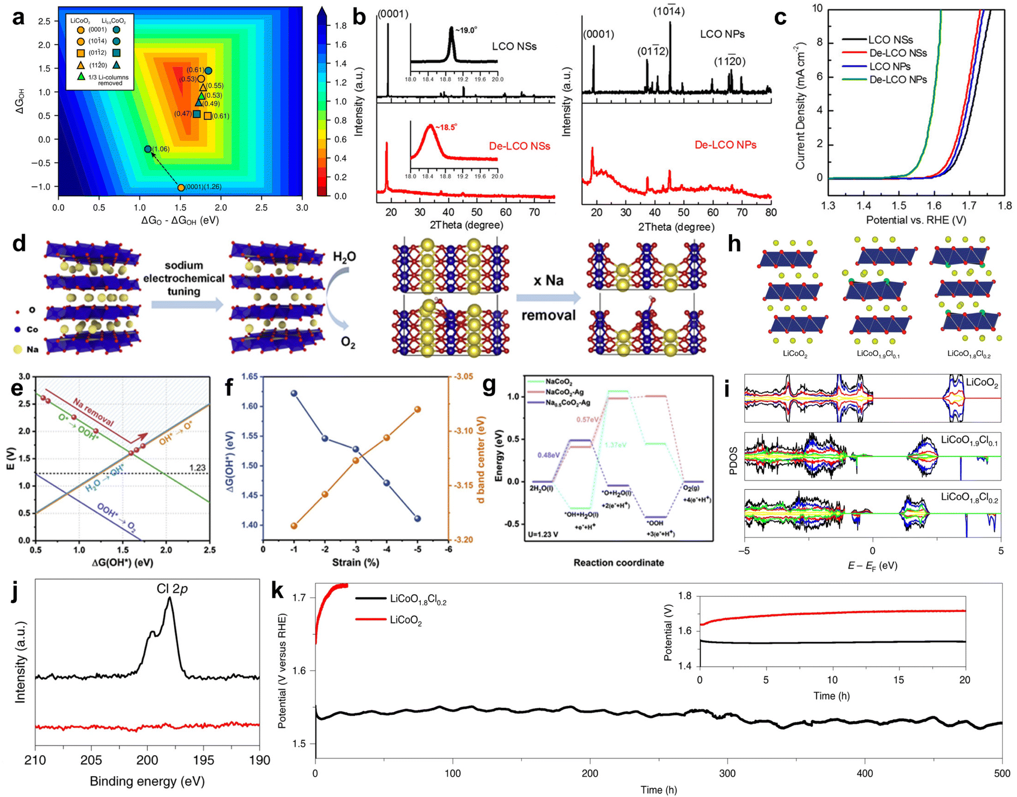 | ||
| Fig. 4 (a) Theoretical calculation of the OER activity of the LiCoO2/Li0.5CoO2 system (theoretical overpotential value). The arrow indicates the change in activity after delithiation. (b) XRD spectra of LCO NSs and LCO NPs before and after delithiation. The illustration shows a local fine XRD pattern. (c) Polarization curves of LCO NSs and LCO NPs before and after delithiation. Adapted with permission from ref. 80. Copyright 2017, American Chemical Society. (d) Schematic diagram of the electrochemical removal of Na+. NaCoO2(100) surface atomic model. (e) Free energy of *OH corresponds to different degrees of Na+ release from NaCoO2. (f) Relationship of the *OH and d-band center free energy of NaCoO2vs. compressive strain. (g) Free energy diagram of the OER process at U = 1.23 V. Adapted with permission from ref. 66. Copyright 2021, Elsevier. (h) Schematic diagram of the atomic structure; Li, yellow; Co, blue; O, Red; Cl, green. (i) PDOS with total (black) and Li, yellow; Co, blue; O, Red; Cl, green. The PDOS of Li and Cl has been magnified by 20 times. (j) Cl 2p XPS: LiCoO1.8Cl0.2 (black) and LiCoO2 (red). (k) Stability at a current density of 20 mA cm−2. Adapted with permission from ref. 83. Copyright 2021, Springer Nature. | ||
In addition, Dai et al. used an electrochemical desorption process to remove sodium from layered NaCoO2, resulting in sodium-deficient Na0.7CoO2 with a certain strain (Fig. 4d). Using ΔG*OH as the catalytic activity indicator for the OER process, the author calculated the Gibbs free energy values of the *OH step under different degrees of desodiation. When the degree of desodiation is at a specific value, there is an optimal Gibbs free energy value (Fig. 4e). The desorption process of Na+ corresponds to a decrease in lattice spacing and the occurrence of strain. Analysis shows that when the strain level is less than 5%, as the strain increases, ΔG*OH decreases and the Co d-band center shifts upwards, indicating an increase in the OER activity (Fig. 4f). Desodiation process has a few improvement in the OER process. Therefore, synchronous Ag+ doping was carried out on this basis. Compressive strain was introduced within the layer while introducing tensile strain between the layers. Through DFT calculations, it was shown that the RDS Gibbs free energy of the catalyst doped with Ag+ and desodiation significantly decreased, greatly improving the OER activity (Fig. 4g). Among them, the overpotential of Ag-Na0.7CoO2 is the lowest 236 mV at 10 mA cm−2, with a minimum Tafel slope of 48 mV dec−1.66 This work provides an interesting approach for interlayer/intralayer modification of layered materials to achieve efficient OERs. Lim et al. prepared a layered LiCoO2−xClx (x = 0, 0.1 or 0.2) by a solid-phase reaction method, and its atomic structure diagram is shown in Fig. 4h. DFT calculations indicate that Cl doping causes the d-band center of the active site to shift towards the Fermi level and the gap between the valence and conduction bands decreases from 2.7 eV of LiCoO2 to 1.3 eV and 1.0 eV of LiCoO1.9Cl0.1 and LiCoO1.8Cl0.2, respectively (Fig. 4i). This indicates that Cl doping enhances the bulk conductivity, which is attributed to a decrease in electron transfer resistance. The author further confirmed the successful doping of Cl by comparing LiCoO2 before and after Cl doping by XPS (Fig. 4j). The doping of Cl reduced the potential for in situ cobalt oxidation and lithium leaching, leading to the transformation of the LiCoO1.8Cl0.2 surface into an amorphous (oxygen) hydroxide phase (CoOOH) during the OER process. In contrast, Cl-free LiCoO2 requires a higher electrochemical potential to initiate surface reconstruction and requires long-term cycling to stabilize it. Therefore, the performance of surface recombination LiCoO1.8Cl0.2 is superior to many state-of-the-art OER catalysts and exhibits significant stability, which can be maintained for 500 hours at a current density of 20 mA cm−2 (Fig. 4k).83 This work provides guidance for designing excellent OER catalysts by controlling in situ leaching of layered materials to regulate surface recombination.
4.3 Perovskites
Perovskites are a large class of oxides, commonly known as ABO3, where A is usually a tombarthite or alkaline metal and B is a transition metal.84 An attractive advantage of perovskite oxides is their high tunability.85,86 However, perovskite oxides typically exhibit cationic leaching behavior, which can lead to the collapse of the perovskite framework during the OER process, greatly reducing the stability of the bulk.87 In addition to having a typical cubic structure, the perovskite family also has a layered structure. The flexibility of this layered perovskite in the configuration also contributes to its tunable electronic structure and stable IrO6 framework.88 This provides a prerequisite for improving the catalytic activity and structural stability of OER catalysts. Sr2IrO4, as a layered perovskite oxide, has a higher mass activity than that of IrO2. However, there are still some unstable factors such as leaching behavior.89,90 Therefore, scientists modify the OER by preparing monolayers, ion exchange, constructing heterostructures, and other forms to achieve the goal of optimizing OER performance. Three-dimensional perovskite SrIrO3 is an OER catalyst with excellent performance, but its stability is poor due to severe Sr leaching during the OER process. Cho et al. constructed a Sr2IrO4/SrIrO3 heterostructure (SrIrO) by modifying 6H phase SrIrO3 with layered Sr2IrO4. Layered Sr2IrO4 is different from the traditional 3D structured perovskite. During the OER process, Sr+ cations between layers can be easily leached while maintaining the IrO6 octahedral framework with shared in-plane angles (Fig. 5a). In this way, both the bulk structure can be stabilized and oxygen can be transported through gaps. In order to better illustrate the structural evolution during the OER process, XPS analysis of SrIrO was performed in 0.1 M HClO4 before and after electrocatalysis for 2 hours. The Sr 3d XPS spectrum is shown in Fig. 5b. Compared to the initial state, the Sr 3d peak of the catalyst significantly weakened after testing, indicating that a large amount of Sr+ leaching formed a Sr deficient surface after electrochemical testing. This further proves the leaching of Sr+ cations through experiments. In addition, Sr leaching can lead to significant surface coarsening, thereby increasing the active surface area and affecting catalytic performance. SrIrO exhibits extremely low overpotential, with an OER of 245 mV at 10 mA cm−2 and excellent catalytic stability in 0.5 M H2SO4.91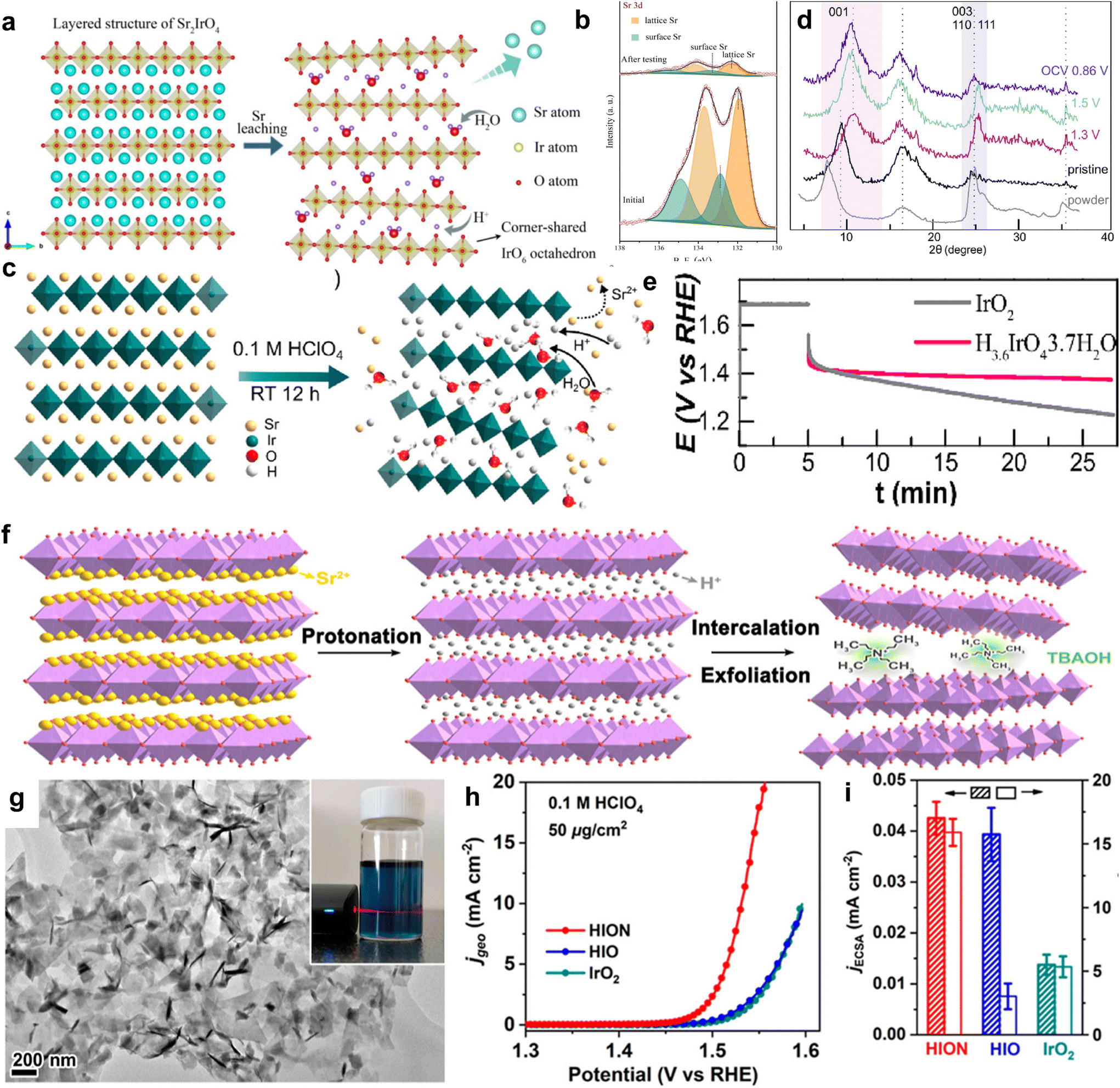 | ||
| Fig. 5 (a) Schematic diagram of the layered structure of Sr2IrO4 and the structure after Sr leaching. (b) XPS spectra of Sr 3d for SrIrO before and after 2 hours of electrocatalysis. Adapted with permission from ref. 91. Copyright 2021, Elsevier. (c) Schematic diagram of Sr2IrO4 and H3.6IrO4·3.7H2O structures. (d) Ex situ XRD patterns of H3.6IrO4·3.7H2O collected at different OER potentials. (e) Stability curve at a constant potential of 1.65 V vs. RHE. Adapted with permission from ref. 92. Copyright 2020, American Chemical Society. (f) Schematic diagram of Sr2IrO4 liquid-phase exfoliation. Sr, yellow; O, red; H, gray; IrO6, purple. (g) TEM image of HION. The illustration shows the dispersion of HION in water, exhibiting The Tyndall effect. (h) Polarization curve of HION in 0.1 M HClO4. (i) ECSA and ECSA-normalized specific activity of HION at 1.53 V vs. RHE. Adapted with permission from ref. 93. Copyright 2022, American Chemical Society. | ||
Grimaud et al. modified layered perovskite Sr2IrO4 by a Sr+/H+ cation exchange for the first time and prepared the protonated phase H3.6IrO4·3.7H2O at room temperature (Fig. 5c). Usually, layered Sr2IrO4 undergoes structural collapse of composite oxides during cationic leaching under acidic conditions, resulting in poor overall catalytic stability. Charge compensation via proton exchange helps avoid the formation of soluble Ir3+ or IrO42−, improving stability. The author further demonstrated the occurrence of Sr+/H+ cation exchange and the generation of protonated phase H3.6IrO4·3.7H2O through ex situ XRD at different OER process potentials. As shown in Fig. 5d, when scanning from an open circuit voltage to 1.3 V vs. RHE, the characteristic peak shifts towards a high angle. This indicates lattice shrinkage, and the volume shrinkage is much greater than the volume reduction caused by Ir4+ oxidation, leading to Ir–O bond shortening, thus attributed to deprotonation and structural water in H3.6IrO4·3.7H2O. In summary, this cation exchange method stabilizes the structure of the layered perovskite material itself, giving it longer stability than that of commercial IrO2 (Fig. 5e).92 On the basis of cation exchange modification of layered perovskite Sr2IrO4, Zou et al. obtained protonated H4IrO4 (HIO) by protonation treatment of layered perovskite Sr2IrO4, and, for the first time, obtained single- or few-layer protonated H4IrO4 (HION) via liquid-phase exfoliation (Fig. 5f). The stripped HION is completely protonated, retaining the layered perovskite structure. The morphological integrity and high dispersibility of these protonated nanosheets result in extremely low Ir loading levels (30 μg cm−2), and it exhibits excellent OER performance, with an activity 10 times that of IrO2 (Fig. 5h). Through experimental results combined with theoretical analysis, it is shown that protonated perovskite nanosheets not only reduce Sr dissolution and structural reconstruction, but also expose more active sites. Moreover, layered perovskite frameworks have suitable electronic structures and efficient active sites to provide high intrinsic activity for OER processes (Fig. 5g). The activity of the catalyst was measured by an electrochemical active surface area (ECSA) method, and the results indicated that after normalization, HION and HIO had basically the same activity, much greater than IrO2, indicating a significant increase in the intrinsic activity of protonated layered perovskite (Fig. 5i).93
4.4 Other natural layered metal oxides
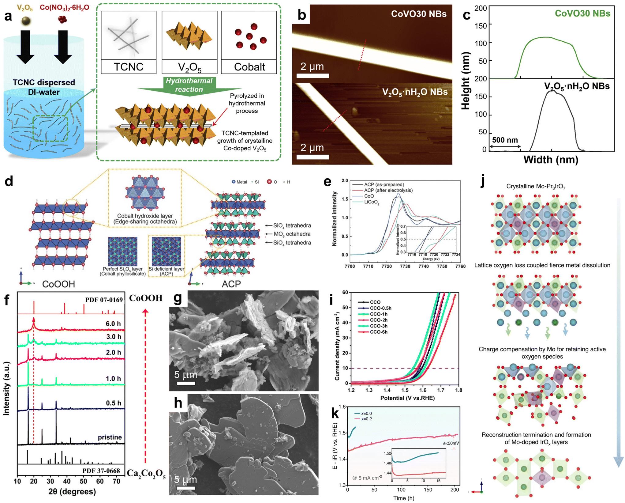 | ||
| Fig. 6 (a) Schematic diagram of the synthesized CoVO NBs. (b) AFM image. (c) AFM measures the width and thickness of V2O5·nH2O NBs and CoVO30 NBs. Adapted with permission from ref. 100. Copyright 2022, Elsevier. (d) Schematic diagram of CoOOH and ACP structures. (e) XANES Co k-edge spectra of ACP before and after CV cycling. For comparison, CoO and LiCoO2 spectra display reference Co2+ and Co3+, respectively. Adapted with permission from ref. 43. Copyright 2017, WILEY. (f) XRD spectra of the original CCO and CCO-xh treated at different times. (g and h) SEM images of CCO-1h and CCO. (i) Polarization curves of COO and COO-xh. Adapted with permission from ref. 106. Copyright 2022, American Chemical Society. (j) Schematic diagram of electrochemical surface reconstruction process of Mo-Pr3IrO7. (k) Chronopotentiometry curves at 5 mA cm−2 in 0.1 M HClO4 electrolyte. Adapted with permission from ref. 107. Copyright 2023, Springer Nature. | ||
| Catalyst | Electrolyte | Overpotential at specific current density | Tafel slope (mV dec−1) | Stability at specific current density | Ref. | |
|---|---|---|---|---|---|---|
| Layered single metal oxides | RuO2 NSs | 0.5 M H2SO4 | 199 mV at 10 mA cm−2 | 38.2 | 5.5 h at 10 mA cm−2 | 73 |
| 1T-IrO2 | 0.1 M HClO4 | 197 mV at 10 mA cm−2 | 49 | 126 h at 250 mA cm−2 | 74 | |
| Ir-MnO2 | 0.5 M H2SO4 | 218 mV at 10 mA cm− | 59.61 | 650 h at 10 mA cm−2 | 70 | |
| Ir-Co3O4 NSs | 0.5 M H2SO4 | 226 mV at 10 mA cm− | 74.4 | 500 h at 10 mA cm−2 | 77 | |
| MCoOx | De-LixCoO2 | 0.1 M KOH | 390 mV at 10 mA cm−2 | 57 | 10 h at 10 mA cm−2 | 80 |
| Ag-Na0.7CoO2 | 1 M KOH | 236 mV at 10 mA cm−2 | 59.2 | 30 h at 10 mA cm−2 | 66 | |
| LiCoO1.8Cl0.2 | 1 M KOH | 290 mV at 40 mA cm−2 | 55.4 | 500 h at 20 mA cm−2 | 83 | |
| Sr2IrO4 | Sr2IrO4/SrIrO3 | 0.5 M H2SO4 | 245 mV at 10 mA cm−2 | 47.4 | 40 h at 10 mA cm−2 | 91 |
| H3.6IrO4·3.7H2O | 0.5 M H2SO4 | 300 mV at 100 A gIr−1 | — | 0.5 h at 1.65 V vs. RHE | 92 | |
| Single layered H4IrO4 | 0.1 M HClO4 | 300 mV at 10 mA cm−2 | 46.9 | 30 h at 10 mA cm−2 | 93 | |
| Co SACs-V2O5·nH2O | 0.1 M KOH | 428 mV at 20 mA cm−2 | 92 | 10 h at 20 mA cm−2 | 100 | |
| Co3Si3O6(OH)6 | 1 M KOH | 367 mV at 10 mA cm−2 | 60 | 24 h at 10 mA cm−2 | 43 | |
| Ca2Co2O5/CoOOH | 1 M KOH | 320 mV at 10 mA cm−2 | 91 | 30 h at 10 mA cm−2 | 101 | |
| Pr3Ir1−xMoxO7 | 0.1 M HClO4 | 259 mV at 10 mA cm−2 | 50.42 | 200 h at 5 mA cm−2 | 102 | |
| Commercial IrO2 | 0.5 M H2SO4 | 397 mV at 10 mA cm−2 | 142.4 | 4 h at 20 mA cm−2 | 103 | |
| 1 M KOH | 386 mV at 10 mA cm−2 | 152.77 | about 4 h at 10 mA cm−2 | 104 |
5. Conclusion and perspectives
In summary, to secure the pivotal role of electrolytic water hydrogen production in the forthcoming energy landscape, the engagement of the OER process is imperative. Because the OER process involves a four-electron transfer step, which requires overcoming large reaction potential barriers and slow kinetics. Investigating novel, efficient, and cost-effective OER electrocatalysts to attain reduced energy consumption in the overall electrolysis of water has emerged as a pivotal research endeavor. LMOs inherently possess natural structural and compositional advantages. Layered architecture has the capability to augment both the specific surface area and the array of active behaviors. Compositionally, metal oxides can function as precursors, undergoing transformation into genuinely active species such as “OOH”. Consequently, investigating layered metal oxide materials as the focal point of OER catalyst research facilitates elucidating the interplay among catalytic properties, mechanisms, and material architectures, thereby enabling the scientific design of electrolytic water catalysts. This article presents the inaugural overview of the recent application of catalysts based on LMOs in the field of OER catalysts. Layered metal oxide-based catalysts are categorized into four groups: single metal oxide (monolayer or few-layer structures acquired through specialized methodologies), alkali cobalt oxide, perovskite, and other metal oxides. The article consolidates the insights into structural advantages, design methodologies, catalytic mechanisms, performance characteristics, and other pertinent facets. The focus is on the necessary connection between the inherent mechanism of catalytic processes and the effective improvement of catalytic properties. For the intrinsic activity of layered metal oxide catalysts, within the framework of the AEM, one crucial consideration entails the adjustment of the d-band center of the transition metal active site to promote the adsorption and desorption of intermediates. In addition, adjustments to the electronic state surrounding oxygen atoms within the catalyst matrix are required to initiate both LOM and OPM while addressing the potential for structural collapse. Ultimately, the overarching objective is to strike a delicate balance between catalytic activity and structural stability.To sum up, the catalytic activity is intricately related to the morphology, composition, coordination environment of active sites, electronic structure, etc., of materials, whereas catalytic stability is closely associated with the coordination environment, chemical bonds, etc., of materials. Despite significant endeavors by researchers in this domain, there remain unresolved issues necessitating thorough investigation in the field of universal design and mechanistic research of OER catalysts.
5.1 Challenges
Although many studies have been conducted on LMOs in the field of OER, there are still many problems that need to be solved: (i) for non-natural layered materials, the method of preparing single-layer or few-layer catalysts is relatively limited, which cannot achieve widespread application. (ii) Conversely, the structural singularity of natural LMOs offers little reference utility for other layered materials, fostering inadvertent design outcomes, resulting in accidental design. (iii) A lack of standardized methodologies for assessing the stability of LMOs exacerbates the challenges within the field, and only a few studies exploring the LOM are involved. (iv) Typically confined to laboratory settings, the application of LMOs in OERs has not yet achieved commercial high-current applications.5.2 Development direction
Conflicts of interest
There are no conflicts to declare.Acknowledgements
This work was jointly supported by the China National Natural Science Foundation (No. 52371236), Natural Science Foundation of Shaanxi Province (No. 2020JM-032), and the Fundamental Scientific Research Project of Xi'an Jiaotong University (xzy022022025).References
- H. Yang, F. Li, S. Zhan, Y. Liu, W. Li, Q. Meng, A. Kravchenko, T. Liu, Y. Yang and Y. Fang, Nat. Catal., 2022, 5, 414–429 CrossRef CAS
.
- X.-L. Zhang, P.-C. Yu, X.-Z. Su, S.-J. Hu, L. Shi, Y.-H. Wang, P.-P. Yang, F.-Y. Gao, Z.-Z. Wu and L.-P. Chi, Sci. Adv., 2023, 9, eadh2885 CrossRef CAS PubMed
- L. E. Heim, D. Thiel, C. Gedig, J. Deska and M. H. Prechtl, Angew. Chem., Int. Ed., 2015, 54, 10308–10312 CrossRef CAS PubMed
- Y. Liu, L. Li, L. Wang, N. Li, X. Zhao, Y. Chen, T. Sakthivel and Z. Dai, Nat. Commun., 2024, 15, 2851 CrossRef CAS PubMed
- N. Kittner, F. Lill and D. M. Kammen, Nat. Energy, 2017, 2, 1–6 Search PubMed
- J. Zhang, Q. Zhang and X. Feng, Adv. Mater., 2019, 31, 1808167 CrossRef
- F. Jiao, J. Wang, Y. Lin, J. Li, X. Jing and Y. Gong, Appl. Surf. Sci., 2021, 553, 149440 CrossRef CAS
- H. Shi, X.-Y. Sun, S.-P. Zeng, Y. Liu, G.-F. Han, T.-H. Wang, Z. Wen, Q.-R. Fang, X.-Y. Lang and Q. Jiang, Small Struct., 2023, 4, 2300042 CrossRef CAS
- Y. A. Situmorang, Z. Zhao, P. An, T. Yu, J. Rizkiana, A. Abudula and G. Guan, Appl. Energy, 2020, 268, 115122 CrossRef CAS
- U. Izquierdo, S. Neuberg, S. Pecov, H. Pennemann, R. Zapf, M. Wichert, V. Barrio, J. Cambra and G. Kolb, Chem. Eng. J., 2017, 313, 1494–1508 CrossRef CAS
- L. Ouyang, J. Jiang, K. Chen, M. Zhu and Z. Liu, Nano-Micro Lett., 2021, 13, 134 CrossRef CAS PubMed
- T. Wang, L. Tao, X. Zhu, C. Chen, W. Chen, S. Du, Y. Zhou, B. Zhou, D. Wang and C. Xie, Nat. Catal., 2022, 5, 66–73 CrossRef CAS
- X. Yan, M. Xia, H. Liu, B. Zhang, C. Chang, L. Wang and G. Yang, Nat. Commun., 2023, 14, 1741 CrossRef CAS PubMed
- Y. Chen, Y. Liu, L. Li, T. Sakthivel, Z. Guo and Z. Dai, Adv. Funct. Mater., 2024, 2401452 CrossRef
- Y. Jiao, Y. Zheng, M. Jaroniec and S. Z. Qiao, Chem. Soc. Rev., 2015, 44, 2060–2086 RSC
- W. Zhai, Y. Chen, Y. Liu, Y. Ma, P. Vijayakumar, Y. Qin, Y. Qu and Z. Dai, Nano-Micro Lett., 2024, 16, 115 CrossRef CAS PubMed
- L. Yao, D. Wei, D. Yan and C. Hu, Chem. – Asian J., 2015, 10, 630–636 CrossRef CAS
- Y. Chen, Y. Liu, W. Zhai, H. Liu, T. Sakthivel, S. Guo and Z. Dai, Adv. Energy Mater., 2024, 2400059 CrossRef
- A. Ali, F. Long and P. K. Shen, Electrochem. Energy Rev., 2022, 5, 1 CrossRef CAS
- J. S. Kim, B. Kim, H. Kim and K. Kang, Adv. Energy Mater., 2018, 8, 1702774 CrossRef
- X. Xu, Y. Pan, L. Ge, Y. Chen, X. Mao, D. Guan, M. Li, Y. Zhong, Z. Hu and V. K. Peterson, Small, 2021, 17, 2101573 CrossRef CAS
- Z. P. Wu, X. F. Lu, S. Q. Zang and X. W. Lou, Adv. Funct. Mater., 2020, 30, 1910274 CrossRef CAS
- P. R. Chowdhury, H. Medhi, K. G. Bhattacharyya and C. M. Hussain, Coord. Chem. Rev., 2023, 483, 215083 CrossRef
- X.-W. Lv, W.-W. Tian and Z.-Y. Yuan, Electrochem. Energy Rev., 2023, 6, 23 CrossRef CAS
- X. Huang, X. Xu, C. Li, D. Wu, D. Cheng and D. Cao, Adv. Energy Mater., 2019, 9, 1803970 CrossRef
- J. Wang, Y. Gao, H. Kong, J. Kim, S. Choi, F. Ciucci, Y. Hao, S. Yang, Z. Shao and J. Lim, Chem. Soc. Rev., 2020, 49, 9154–9196 RSC
- Q. Wang, Z. Zhang, C. Cai, M. Wang, Z. L. Zhao, M. Li, X. Huang, S. Han, H. Zhou and Z. Feng, J. Am. Chem. Soc., 2021, 143, 13605–13615 CrossRef CAS PubMed
- M. Li, X. Wang, K. Liu, H. Sun, D. Sun, K. Huang, Y. Tang, W. Xing, H. Li and G. Fu, Adv. Mater., 2023, 35, 2302462 CrossRef CAS PubMed
- S. Roy, P. Dahiya, T. K. Mandal and S. Roy, Dalton Trans., 2024, 53, 5484–5494 RSC
- H. Yan, Z. Jiang, B. Deng, Y. Wang and Z. J. Jiang, Adv. Energy Mater., 2023, 13, 2300152 CrossRef CAS
- R. Lin, T. Lin, J. Huang, X. Huang and Y. Liu, Electrochim. Acta, 2018, 281, 348–356 CrossRef CAS
- J. Ban, H. Xu, G. Cao, Y. Fan, W. K. Pang, G. Shao and J. Hu, Adv. Funct. Mater., 2023, 33, 2300623 CrossRef CAS
- Y. Wang, Y. Jiao, H. Yan, G. Yang, C. Tian, A. Wu, Y. Liu and H. Fu, Angew. Chem., 2022, 134, e202116233 CrossRef
- Z. Jiang, W. Zhou, C. Hu, X. Luo, W. Zeng, X. Gong, Y. Yang, T. Yu, W. Lei and C. Yuan, Adv. Mater., 2023, 35, 2300505 CrossRef CAS PubMed
- Y. Cao, Y. Wen, Y. Li, M. Cao, B. Li, Q. Shen and W. Gu, Dalton Trans., 2024, 53, 5291–5300 RSC
- J.-Y. Luo, Y. Yuan, H.-Y. Ruan, X.-Q. Wu, Y.-P. Wu, S. Li, G. Zhang, S. Sun and D.-S. Li, Small Struct., 2023, 4, 2300074 CrossRef CAS
- M. Bachhav, G. Pawar, F. Vurpillot, R. L. Danoix, F. D. R. Danoix, B. Hannoyer, Y. Dong and E. Marquis, J. Phys. Chem. C, 2018, 123, 1313–1319 CrossRef
- T. C. Ozawa and S. M. Kauzlarich, Sci. Technol. Adv. Mater., 2008, 9, 033003 CrossRef PubMed
- D. Weber, L. M. Schoop, D. Wurmbrand, J. R. Nuss, E. M. Seibel, F. F. Tafti, H. Ji, R. J. Cava, R. E. Dinnebier and B. V. Lotsch, Chem. Mater., 2017, 29, 8338–8345 CrossRef CAS
- S. Hao, M. Liu, J. Pan, X. Liu, X. Tan, N. Xu, Y. He, L. Lei and X. Zhang, Nat. Commun., 2020, 11, 5368 CrossRef CAS PubMed
- F. Geng, R. Ma, Y. Ebina, Y. Yamauchi, N. Miyamoto and T. Sasaki, J. Am. Chem. Soc., 2014, 136, 5491–5500 CrossRef CAS PubMed
- M. E. Strayer, T. P. Senftle, J. P. Winterstein, N. M. Vargas-Barbosa, R. Sharma, R. M. Rioux, M. J. Janik and T. E. Mallouk, J. Am. Chem. Soc., 2015, 137, 16216–16224 CrossRef CAS PubMed
- J. S. Kim, I. Park, E. S. Jeong, K. Jin, W. M. Seong, G. Yoon, H. Kim, B. Kim, K. T. Nam and K. Kang, Adv. Mater., 2017, 29, 1606893 CrossRef PubMed
- Q. Wang, K. Dastafkan and C. Zhao, Curr. Opin. Electrochem., 2018, 10, 16–23 CrossRef CAS
- P. Ganter, L. M. Schoop and B. V. Lotsch, Adv. Mater., 2016, 29, 1604884 CrossRef PubMed
- S. Jin, Journal, 2017, 2, 1937–1938 CAS
- X. Cai, R. Ma, T. C. Ozawa, N. Sakai, A. Funatsu and T. Sasaki, Nanoscale, 2014, 6, 14419–14427 RSC
- A. S. Gupta, H. Akamatsu, F. G. Brown, M. A. T. Nguyen, M. E. Strayer, S. Lapidus, S. Yoshida, K. Fujita, K. Tanaka, I. Tanaka, T. E. Mallouk and V. Gopalan, Chem. Mater., 2017, 29, 656–665 CrossRef
- H. Ishaq, I. Dincer and C. Crawford, Int. J. Hydrogen Energy, 2022, 47, 26238–26264 CrossRef CAS
- N. M. Dowell, N. Sunny, N. Brandon, H. Herzog, A. Y. Ku, W. Maas, A. Ramirez, D. M. Reiner, G. N. Sant and N. Shah, Joule, 2021, 5, 2524–2529 CrossRef
- X. Ren, L. Dong, D. Xu and B. Hu, Int. J. Hydrogen Energy, 2020, 45, 34326–34345 CrossRef CAS
- S. Zhiznin, V. Timokhov and A. Gusev, Int. J. Hydrogen Energy, 2020, 45, 31353–31366 CrossRef CAS
- A. Grimaud, O. Diaz-Morales, B. Han, W. T. Hong, Y.-L. Lee, L. Giordano, K. A. Stoerzinger, M. T. Koper and Y. Shao-Horn, Nat. Chem., 2017, 9, 457–465 CrossRef CAS PubMed
- W. Zhai, Y. Chen, Y. Liu, T. Sakthivel, Y. Ma, Y. Qin, Y. Qu and Z. Dai, ACS Nano, 2023, 17, 17254–17264 CrossRef CAS PubMed
- M. Okamura, M. Kondo, R. Kuga, Y. Kurashige, T. Yanai, S. Hayami, V. K. Praneeth, M. Yoshida, K. Yoneda and S. Kawata, Nature, 2016, 530, 465–468 CrossRef CAS PubMed
- Y. Liu, T. Sakthivel, F. Hu, Y. Tian, D. Wu, E. H. Ang, H. Liu, S. Guo, S. Peng and Z. Dai, Adv. Energy Mater., 2023, 13, 2203797 CrossRef CAS
- J. Shan, Y. Zheng, B. Shi, K. Davey and S.-Z. Qiao, ACS Energy Lett., 2019, 4, 2719–2730 CrossRef CAS
- R. Gao, J. Zhu and D. Yan, Nanoscale, 2021, 13, 13593–13603 RSC
- L. Li, P. Wang, Q. Shao and X. Huang, Chem. Soc. Rev., 2020, 49, 3072–3106 RSC
- N.-T. Suen, S.-F. Hung, Q. Quan, N. Zhang, Y.-J. Xu and H. M. Chen, Chem. Soc. Rev., 2017, 46, 337–365 RSC
- L. Gao, X. Cui, C. D. Sewell, J. Li and Z. Lin, Chem. Soc. Rev., 2021, 50, 8428–8469 RSC
- T. Qiu, B. Tu, D. Saldana-Greco and A. M. Rappe, ACS Catal., 2018, 8, 2218–2224 CrossRef CAS
- L. Hu, L. Wu, M. Liao, X. Hu and X. Fang, Adv. Funct. Mater., 2012, 22, 998–1004 CrossRef CAS
- J. Suntivich, K. J. May, H. A. Gasteiger, J. B. Goodenough and Y. Shao-Horn, Science, 2011, 334, 1383–1385 CrossRef CAS PubMed
- A. Vojvodic and J. K. Nørskov, Science, 2011, 334, 1355–1356 CrossRef CAS PubMed
- L. Sun, Z. Dai, L. Zhong, Y. Zhao, Y. Cheng, S. Chong, G. Chen, C. Yan, X. Zhang and H. Tan, Appl. Catal., B, 2021, 297, 120477 CrossRef CAS
- Y. Pan, X. Xu, Y. Zhong, L. Ge, Y. Chen, J.-P. M. Veder, D. Guan, R. O'Hayre, M. Li and G. Wang, Nat. Commun., 2020, 11, 2002 CrossRef CAS PubMed
- W. T. Hong, M. Risch, K. A. Stoerzinger, A. Grimaud, J. Suntivich and Y. Shao-Horn, Energy Environ. Sci., 2015, 8, 1404–1427 RSC
- P. R. Chowdhury, H. Medhi, K. G. Bhattacharyya and C. M. Hussain, Coord. Chem. Rev., 2024, 501, 215547 CrossRef
- Z. Shi, Y. Wang, J. Li, X. Wang, Y. Wang, Y. Li, W. Xu, Z. Jiang, C. Liu and W. Xing, Joule, 2021, 5, 2164–2176 CrossRef CAS
- T. Reier, H. N. Nong, D. Teschner, R. Schlögl and P. Strasser, Adv. Energy Mater., 2017, 7, 1601275 CrossRef
- S. Yagi, I. Yamada, H. Tsukasaki, A. Seno, M. Murakami, H. Fujii, H. Chen, N. Umezawa, H. Abe and N. Nishiyama, Nat. Commun., 2015, 6, 8249 CrossRef PubMed
- Z. L. Zhao, Q. Wang, X. Huang, Q. Feng, S. Gu, Z. Zhang, H. Xu, L. Zeng, M. Gu and H. Li, Energy Environ. Sci., 2020, 13, 5143–5151 RSC
- Q. Dang, H. Lin, Z. Fan, L. Ma, Q. Shao, Y. Ji, F. Zheng, S. Geng, S.-Z. Yang and N. Kong, Nat. Commun., 2021, 12, 6007 CrossRef CAS PubMed
- S. Wang, T. Shen, C. Yang, G. Luo and D. Wang, ACS Catal., 2023, 13, 8670–8691 CrossRef CAS
- S. Ge, R. Xie, B. Huang, Z. Zhang, H. Liu, X. Kang, S. Hu, S. Li, Y. Luo and Q. Yu, Energy Environ. Sci., 2023, 16, 3734–3742 RSC
- Y. Liu, Y. Chen, X. Mu, Z. Wu, X. Jin, J. Li, Y. Xu, L. Yang, X. Xi and H. Jang, ACS Catal., 2023, 13, 3757–3767 CrossRef CAS
- M. S. Islam, M. Kim, X. Jin, S. M. Oh, N.-S. Lee, H. Kim and S.-J. Hwang, ACS Energy Lett., 2018, 3, 952–960 CrossRef CAS
- Z. Dai, U. Mani, H. T. Tan and Q. Yan, Small Methods, 2017, 1, 1700098 CrossRef
- Z. Lu, G. Chen, Y. Li, H. Wang, J. Xie, L. Liao, C. Liu, Y. Liu, T. Wu and Y. Li, J. Am. Chem. Soc., 2017, 139, 6270–6276 CrossRef CAS PubMed
- Z. Lu, H. Wang, D. Kong, K. Yan, P.-C. Hsu, G. Zheng, H. Yao, Z. Liang, X. Sun and Y. Cui, Nat. Commun., 2014, 5, 4345 CrossRef CAS PubMed
- Z. Lu, K. Jiang, G. Chen, H. Wang and Y. Cui, Adv. Mater., 2018, 30, 1800978 CrossRef PubMed
- J. Wang, S.-J. Kim, J. Liu, Y. Gao, S. Choi, J. Han, H. Shin, S. Jo, J. Kim and F. Ciucci, Nat. Catal., 2021, 4, 212–222 CrossRef CAS
- Y. Chen, H. Li, J. Wang, Y. Du, S. Xi, Y. Sun, M. Sherburne, J. W. Ager III, A. C. Fisher and Z. J. Xu, Nat. Commun., 2019, 10, 572 CrossRef CAS PubMed
- R. Tang, Y. Nie, J. K. Kawasaki, D.-Y. Kuo, G. Petretto, G. Hautier, G.-M. Rignanese, K. M. Shen, D. G. Schlom and J. Suntivich, J. Mater. Chem. A, 2016, 4, 6831–6836 RSC
- A. Grimaud, A. Demortière, M. Saubanère, W. Dachraoui, M. Duchamp, M.-L. Doublet and J.-M. Tarascon, Nat. Energy, 2016, 2, 1–10 Search PubMed
- H. J. Song, H. Yoon, B. Ju and D. W. Kim, Adv. Energy Mater., 2021, 11, 2002428 CrossRef CAS
- C. Sun, J. A. Alonso and J. Bian, Adv. Energy Mater., 2021, 11, 2000459 CrossRef CAS
- Y. K. Kim, N. Sung, J. Denlinger and B. Kim, Nat. Phys., 2016, 12, 37–41 Search PubMed
- H. Tsai, W. Nie, J.-C. Blancon, C. C. Stoumpos, R. Asadpour, B. Harutyunyan, A. J. Neukirch, R. Verduzco, J. J. Crochet and S. Tretiak, Nature, 2016, 536, 312–316 CrossRef CAS PubMed
- L. Zhang, H. Jang, Z. Li, H. Liu, M. G. Kim, X. Liu and J. Cho, Chem. Eng. J., 2021, 419, 129604 CrossRef CAS
- R. Zhang, P. E. Pearce, V. Pimenta, J. Cabana, H. Li, D. A. D. Corte, A. M. Abakumov, G. Rousse, D. Giaume and M. Deschamps, Chem. Mater., 2020, 32, 3499–3509 CrossRef CAS
- H. Chen, L. Shi, K. Sun, K. Zhang, Q. Liu, J. Ge, X. Liang, B. Tian, Y. Huang and Z. Shi, ACS Catal., 2022, 12, 8658–8666 CrossRef CAS
- T. Wu, K. Zhu, C. Qin and K. Huang, J. Mater. Chem. A, 2019, 7, 5612–5620 RSC
- M. Liu, B. Su, Y. Tang, X. Jiang and A. Yu, Adv. Energy Mater., 2017, 7, 1700885 CrossRef
- A. S. Etman, H. D. Asfaw, N. Yuan, J. Li, Z. Zhou, F. Peng, I. Persson, X. Zou, T. Gustafsson and K. Edström, J. Mater. Chem. A, 2016, 4, 17988–18001 RSC
- D. Kundu, B. D. Adams, V. Duffort, S. H. Vajargah and L. F. Nazar, Nat. Energy, 2016, 1, 1–8 Search PubMed
- K. Fan, H. Chen, Y. Ji, H. Huang, P. M. Claesson, Q. Daniel, B. Philippe, H. Rensmo, F. Li and Y. Luo, Nat. Commun., 2016, 7, 11981 CrossRef CAS PubMed
- A. Moretti, F. Maroni, I. Osada, F. Nobili and S. Passerini, ChemElectroChem, 2015, 2, 529–537 CrossRef CAS
- C. Youn, S. Shin, K. Shin, C. Kim, C.-L. Park, J. Choi, S. H. Kim, S. Y. Yeo, M. W. Shin and G. Henkelman, Chem Catal., 2022, 2, 1191–1210 CrossRef CAS
- S. Song, L. Mu, Y. Jiang, J. Sun, Y. Zhang, G. Shi and H. Sun, ACS Appl. Mater. Interfaces, 2022, 14, 47560–47567 CrossRef CAS PubMed
- S. Chen, S. Zhang, L. Guo, L. Pan, C. Shi, X. Zhang, Z.-F. Huang, G. Yang and J.-J. Zou, Nat. Commun., 2023, 14, 4127 CrossRef CAS PubMed
- X. Zheng, J. Yang, P. Li, Q. Wang, J. Wu, E. Zhang, S. Chen, Z. Zhuang, W. Lai and S. Dou, Sci. Adv., 2023, 9, eadi8025 CrossRef CAS PubMed
- M. Hou, L. Zheng, D. Zhao, X. Tan, W. Feng, J. Fu, T. Wei, M. Cao, J. Zhang and C. Chen, Nat. Commun., 2024, 15, 1342 CrossRef CAS PubMed
- J. Park, H. Kim, K. Jin, B. J. Lee, Y.-S. Park, H. Kim, I. Park, K. D. Yang, H.-Y. Jeong and J. Kim, J. Am. Chem. Soc., 2014, 136, 4201–4211 CrossRef CAS PubMed
- K. A. Stoerzinger, W. S. Choi, H. Jeen, H. N. Lee and Y. Shao-Horn, J. Phys. Chem. Lett., 2015, 6, 487–492 CrossRef CAS PubMed
- A. Grimaud, C. E. Carlton, M. Risch, W. T. Hong, K. J. May and Y. Shao-Horn, J. Phys. Chem. C, 2013, 117, 25926–25932 CrossRef CAS
- D. K. Bediako, Y. Surendranath and D. G. Nocera, J. Am. Chem. Soc., 2013, 135, 3662–3674 CrossRef CAS PubMed
- A. M. Ullman, C. N. Brodsky, N. Li, S.-L. Zheng and D. G. Nocera, J. Am. Chem. Soc., 2016, 138, 4229–4236 CrossRef CAS PubMed
- Z. J. Xu, Sci. China Mater., 2020, 63, 3–7 CrossRef CAS
- Y. Li, X. Du, J. Huang, C. Wu, Y. Sun, G. Zou, C. Yang and J. Xiong, Small, 2019, 15, 1901980 CrossRef PubMed
- H. Li, Y. Chen, J. Ge, X. Liu, A. C. Fisher, M. P. Sherburne, J. W. Ager and Z. J. Xu, JACS Au, 2021, 1, 108–115 CrossRef CAS PubMed
- H. Li, Y. Chen, J. Z. Y. Seow, C. Liu, A. C. Fisher, J. W. Ager and Z. J. Xu, Small Sci., 2022, 2, 2100048 CrossRef CAS
- S. Song, H. Bao, X. Lin, X.-L. Du, J. Zhou, L. Zhang, N. Chen, J. Hu and J.-Q. Wang, J. Energy Chem., 2020, 42, 5–10 CrossRef
- S. Ye, J. Wang, J. Hu, Z. Chen, L. Zheng, Y. Fu, Y. Lei, X. Ren, C. He and Q. Zhang, ACS Catal., 2021, 11, 6104–6112 CrossRef CAS
- Q. Qin, H. Jang, Y. Wang, L. Zhang, Z. Li, M. G. Kim, S. Liu, X. Liu and J. Cho, Adv. Energy Mater., 2021, 11, 2003561 CrossRef CAS
- Z. Wang, Y.-R. Zheng, I. Chorkendorff and J. K. Nørskov, ACS Energy Lett., 2020, 5, 2905–2908 CrossRef CAS
- W. Zhu, F. Yao, K. Cheng, M. Zhao, C.-J. Yang, C.-L. Dong, Q. Hong, Q. Jiang, Z. Wang and H. Liang, J. Am. Chem. Soc., 2023, 145, 17995–18006 CrossRef CAS PubMed
- R. Li, B. Hu, T. Yu, H. Chen, Y. Wang and S. Song, Adv. Sci., 2020, 7, 1902830 CrossRef CAS PubMed
- K. Xiao, Y. Wang, P. Wu, L. Hou and Z. Q. Liu, Angew. Chem., 2023, 135, e202301408 CrossRef
- S. Liu, H. Tan, Y. C. Huang, Q. Zhang, H. Lin, L. Li, Z. Hu, W. H. Huang, C. W. Pao and J. F. Lee, Adv. Mater., 2023, 35, 2305659 CrossRef CAS PubMed
- Z.-Y. Wu, F.-Y. Chen, B. Li, S.-W. Yu, Y. Z. Finfrock, D. M. Meira, Q.-Q. Yan, P. Zhu, M.-X. Chen and T.-W. Song, Nat. Mater., 2023, 22, 100–108 CrossRef CAS PubMed
- M. F. Lagadec and A. Grimaud, Nat. Mater., 2020, 19, 1140–1150 CrossRef CAS PubMed
- H. B. Yang and B. Liu, Chem Catal., 2021, 1, 1365–1366 CrossRef CAS
| This journal is © The Royal Society of Chemistry 2024 |