DOI:
10.1039/D0SM01727B
(Paper)
Soft Matter, 2021,
17, 3594-3602
Wetting equilibrium in a rectangular channel
Received
26th September 2020
, Accepted 3rd December 2020
First published on 7th December 2020
Abstract
When a capillary channel with corners is wetted by a fluid, there are regions where the fluid fills the whole cross-section and regions where only the corners are filled by the fluid. The fluid fraction of the partially-filled region, s*, is an important quantity related to the capillary pressure. We calculate the value of s* for channels with a cross-section slightly deviated from a rectangle: the height is larger in the center than those on the two short sides. We find that a small change in the cross-section geometry leads to a huge change of s*. This result is consistent with experimental observations.
1 Introduction
Wetting and drying in porous media are ubiquitous phenomena in our daily life.1–3 They are also important in many applications, including environmental science, oil recovery, and processes in food, textile, and pharmaceutical research. Porous media have complicated structures involving wide distribution of pore size and various junction geometries, which make the comprehensive understanding difficult. Simplified structures have been used to understand the fluid transportation in porous media, such as capillary tubes with corners.4 One beautiful example is the study of the evaporation in a capillary tube,5 where the drying dynamics in a simple square tube resembles that in a porous medium.
An important quantity governing the capillary phenomena in porous media is the capillary pressure pc,1 defined as the pressure difference across the interfaces separating two phases (normally one is air and the other one is fluid). If the shape of the meniscus is known, the capillary pressure is given by the Laplace pressure
| |  | (1) |
where
γ is the surface tension of the fluid,
r1 and
r2 are the meniscus' two principal radii of curvature, and
r* is the mean radius of curvature (2/
r* = 1/
r1 + 1/
r2). In a capillary tube with corners, the fluid can either fill up the whole cross-section or only part of the cross-section, with a transition region connecting them (see
Fig. 2). At equilibrium, the capillary pressure is equal at every point of the meniscus, one then has the freedom to choose where to calculate the capillary pressure. It turns out that the calculation is easier at the partially filled region because one of the principal curvatures (along the tube axis) is zero. This is the method proposed first by Mayer and Stowe
6 and Princen,
7–9 and extended later by Mason and Morrow.
10 One related quantity is the saturation of the partially filled region, which we will describe as
s*. The relation between
pc and
s* will be given later [
eqn (31)]. In this work, we shall discuss the value of
s* for a capillary channel with a cross-section slightly deviated from a rectangle.
Two recent studies in rectangular channels motivated our study. Keita et al.11 studied the drying dynamics in a nearly-rectangular channel, the thickness of which is slightly larger in the middle than in the edges (the thickness is 115 μm in the middle and 95 μm at the edges; the width of the channel is 2 mm). During the evaporation, two thick fluid fingers were present in the partially-saturated region (left column in Fig. 1). This is in contrast to a later study by Seck et al.12 In this case, the rectangular channel was nearly perfect, and very thin fluid columns were observed (right column in Fig. 1). These two experiments clearly showed that a slight deviation from the rectangular geometry changes the value of s* enormously. The purpose of this paper is to explain these phenomena based on a free energy model.
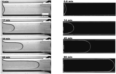 |
| | Fig. 1 Top views of the nearly-rectangular channel (open to the left) at different drying times. The left column is from ref. 11, in which the height of the cross-section is large in the middle. The right column is from ref. 12, in which the cross-section is a nearly-perfect rectangle. (Reprinted from ref. 11 and 12 with permission from the Springer Nature.) | |
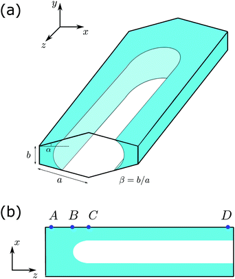 |
| | Fig. 2 (a) Schematic picture of partially-filled channel with a cross-section slightly deviated from a rectangle. The cross-section is characterized by the top/bottom edge 2a, side edge b, leading to an aspect ratio β = b/a. These two sides form an angle that is slightly larger than the normal angle by α. The channel is filled partially by a fully wetting fluid with the equilibrium contact angle θE = 0. (b) The view from the cutting x–z plane. The AB part is fully filled by the fluid and CD is partially filled, with a transition region BC in between. In these pictures, the channel is sealed by a wetting material at the end near A and a neutral material at the end near D. | |
2 Model
We consider a capillary channel with a cross-section slightly deviated from a rectangle. The channel is horizontally placed along the z-direction, as illustrated in Fig. 2(a). The total length of the long side is 2a and the short side of the cross-section has a length of b. For convenience, we define a length ratio β = b/a, and we shall focus on the situation when this ratio is small, β < 1. The two sides (a and b) form an angle of π/2 + α, which is slightly larger than the normal angle. We focus on the situation that α is small, corresponding to the case that the cross-section is quite close to a rectangle.
Now we place some wetting fluid into the channel and seal both ends. The amount of fluid is chosen such that the fluid only partially fills the channel, as shown schematically in Fig. 2(a). In the thermodynamic equilibrium, some portion of the channel is fully filled by the fluid with the saturation s = 1 (the saturation s is defined as the area fraction occupied by the fluid in the x–y cross-section), and some portion is only partially filled with a saturation s* < 1. Our goal is to determine the value of s*, and how its value varies when other geometrical parameters, such as α and β, change.
The coexistence between the fully-filled region and partially-filled region can be seen more clearly in the cutting x–z plane shown in Fig. 2(b): The AB part corresponds to full saturation s = 1, while the CD part corresponds to the partial saturation s*. We shall refer the fully-saturated region “bulk” and the partially-saturated region “finger”. There is a transition region BC going from the bulk to the finger. The length of the transition region is finite and with a characteristic size of a. The effect of the transition zone can be neglected in the thermodynamic limit when the length of the bulk (AB) and the finger (CD) both become larger than the length of the transition zone (BC).13,14 The fluid has a surface tension γ and an equilibrium contact angle θE. In the cornered geometry, only when the condition
| |  | (2) |
is fulfilled, the partially-filled portion is possible.
15 In this study we focus on the fully-wetted fluid,
i.e., the contact angle
θE = 0. For the fully-wetted fluid, the above condition
(2) is satisfied when
α < π/2. Since we are interested in the case when
α is small, condition
(2) is automatically satisfied. We assume that the channel height
b is less than the capillary length, so the effect of the gravity can be neglected. The smallest dimension of the channel (also
b here) should be larger than a few nanometers, thus the fluid surface is well-defined. The only contribution to the energy is the interfacial energy.
3 Free energy density
In the x–y plane, the liquid–vapor interface of the meniscus in the finger region is part of a circle. Possible shapes of the meniscus are illustrated in Fig. 3. We define f(s) as the free energy density of the wetting liquid as the free energy per unit length along the z axis, which can be expressed as a function of the saturation s. For the nearly-rectangular channel, we distinguish three cases of wetting scenarios, based on whether the vapor–solid interfaces exist and how the contact lines intersect the side walls.
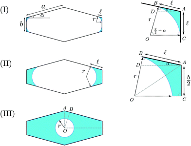 |
| | Fig. 3 Three scenarios of the wetting liquid in the cross-section of a nearly-rectangular channel. (I) The liquid–vapor interfaces form four separated arcs in the corners. (II) The liquid–vapor interfaces form two separated arcs in the corners, with the b side is fully covered by the fluid. (III) The liquid–vapor interface is a full circle, with the perimeter of the cross-section all covered by the fluid. | |
3.1 Case (I)
The situation is shown in Fig. 3(I). The liquid–vapor interfaces are composed of four separate arcs in the corners. There are solid surfaces exposed to the vapor in both a side and b side. Since the value of α is small, we assume that the liquid doesn't wet in the two corners constructed by the two adjacent a sides. The radius of curvature of the liquid–vapor interface is denoted by r, and ![[small script l]](https://www.rsc.org/images/entities/char_e146.gif) is the wetting length on the a side. The radius r can be expressed as a function of
is the wetting length on the a side. The radius r can be expressed as a function of ![[small script l]](https://www.rsc.org/images/entities/char_e146.gif)
| |  | (3) |
The area occupied by the fluid is the area of quadrilateral ABOC minus the sector OBC (counting 4 corners)| |  | (4) |
The total area is a constant| | S0 = 2a![[thin space (1/6-em)]](https://www.rsc.org/images/entities/char_2009.gif) cos cos![[thin space (1/6-em)]](https://www.rsc.org/images/entities/char_2009.gif) αb + 2a αb + 2a![[thin space (1/6-em)]](https://www.rsc.org/images/entities/char_2009.gif) cos cos![[thin space (1/6-em)]](https://www.rsc.org/images/entities/char_2009.gif) αa αa![[thin space (1/6-em)]](https://www.rsc.org/images/entities/char_2009.gif) sin sin![[thin space (1/6-em)]](https://www.rsc.org/images/entities/char_2009.gif) α = 2a2 α = 2a2![[thin space (1/6-em)]](https://www.rsc.org/images/entities/char_2009.gif) cos cos![[thin space (1/6-em)]](https://www.rsc.org/images/entities/char_2009.gif) α(sin α(sin![[thin space (1/6-em)]](https://www.rsc.org/images/entities/char_2009.gif) α + β), α + β), | (5) |
from which we can calculate the saturation s| |  | (6) |
Since there are solid surfaces exposed to the vapor, the range of ![[small script l]](https://www.rsc.org/images/entities/char_e146.gif) is limited by
is limited by ![[small script l]](https://www.rsc.org/images/entities/char_e146.gif) < b/2. This leads to the following constraint on the saturation
< b/2. This leads to the following constraint on the saturation
| |  | (8) |
The free energy density f(s) is expressed as
| |  | (9) |
where
γSL and
γSV are the interfacial tensions between solid/liquid and solid/vapor, respectively. Here we have used Young's equation
γ![[thin space (1/6-em)]](https://www.rsc.org/images/entities/char_2009.gif)
cos
![[thin space (1/6-em)]](https://www.rsc.org/images/entities/char_2009.gif) θE
θE =
γSV −
γSL and zero equilibrium contact angle
θE = 0. We choose a dried surface as the reference point for the free energy. For the case of total wetting, there might be a precursor film of molecular thickness.
2,3,16 The first term in
eqn (9) is modified as 8
![[small script l]](https://www.rsc.org/images/entities/char_e146.gif)
(
γSL − (
γ +
γSL)), and the final expression remains valid.
Using eqn (3) and (6), the free energy density can be written as a function of s
| |  | (10) |
| |  | (11) |
3.2 Case (II)
This situation is shown in Fig. 3(II). Compared to case (I), the two fingers on the b sides merge into one finger. In this case, the vapor–solid interfaces only exist on the a sides. The radius r is expressed as a function of ![[small script l]](https://www.rsc.org/images/entities/char_e146.gif) as
as| |  | (12) |
The area occupied by the fluid is the summation of the triangle ABD and trapezoid ACOD minus the sector OB (counting 4 corners)| |  | (13) |
Using eqn (12), the saturation s is given in terms of ![[small script l]](https://www.rsc.org/images/entities/char_e146.gif) ,
,| | 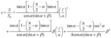 | (14) |
The saturation s in this case has two limits. The lower bound sc1 is given by eqn (8) and the upper bound is constrained by ![[small script l]](https://www.rsc.org/images/entities/char_e146.gif) < a,
< a,
| | 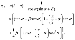 | (16) |
The free energy density f(s) is expressed as
| |  | (17) |
| |  | (18) |
Here an explicit expression of the free energy density as a function of saturation is complicated, and it is easier to use
![[small script l]](https://www.rsc.org/images/entities/char_e146.gif)
as an intermediate variable. The range of
![[small script l]](https://www.rsc.org/images/entities/char_e146.gif)
is
b/2 ≤
![[small script l]](https://www.rsc.org/images/entities/char_e146.gif)
<
a, leading to the two bounds
sc1 and
sc2 for the saturation. The saturation and the free energy density as functions of
![[small script l]](https://www.rsc.org/images/entities/char_e146.gif)
are given by
eqn (14) and (18), respectively.
3.3 Case (III)
This situation is shown in Fig. 3(III). When the solid–vapor interfaces disappear, the liquid–vapor interface becomes a full circle of radius r. The saturation is given as a function of r| |  | (19) |
The radius is constrained by the shortest distance from the center to the a side| |  | (20) |
This leads to a lower bound for the saturation| |  | (22) |
The free energy density f(s) is expressed as
| | | f(s) = −(4a + 2b)γ + 2πrγ, | (23) |
| |  | (24) |
The free energy density at full saturation (s = 1) is
| |  | (25) |
As a summary, the free energy densities for the three cases are listed below
Examples of free energy curves for
β = 0.095 are shown in
Fig. 4(a) and (b) for tan
![[thin space (1/6-em)]](https://www.rsc.org/images/entities/char_2009.gif) α
α = 0.002 and 0.1, respectively. The aspect ratio
β takes the value in experiments of
ref. 11.
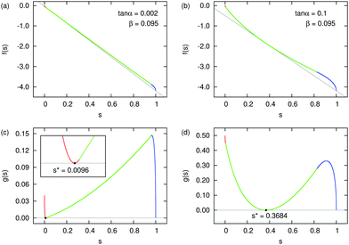 |
| | Fig. 4 Example free energy density f(s) as a function of the saturation s for β = 0.095. (a) tan![[thin space (1/6-em)]](https://www.rsc.org/images/entities/char_2009.gif) α = 0.002. (b) tan α = 0.002. (b) tan![[thin space (1/6-em)]](https://www.rsc.org/images/entities/char_2009.gif) α = 0.1. The different colors of the curves correspond to the three cases [red (I), green (II), and blue (III)]. The coexistence conditions of (32) are shown with gray lines. (c) and (d) The function g(s) [eqn (33)] corresponding to (a) and (b). In (c), s* locates in case (I) and in (d), s* locates in case (II). α = 0.1. The different colors of the curves correspond to the three cases [red (I), green (II), and blue (III)]. The coexistence conditions of (32) are shown with gray lines. (c) and (d) The function g(s) [eqn (33)] corresponding to (a) and (b). In (c), s* locates in case (I) and in (d), s* locates in case (II). | |
4 Saturation s*
Once we have an expression of the free energy density as a function of saturation, we need a criterion to determine the partial saturation s*. This will be derived in the following.
4.1 Coexistence condition
Suppose the total length of the channel is L and the area of the cross-section is S0. The total volume of the fluid is Vl < LS0. Along the channel, a fraction ϕ is partially saturated with a saturation s < 1, and the remaining fraction (1 − ϕ) is fully saturated by the fluid (s = 1). Here we have neglected the contribution from the transition region. The total free energy is given by| | | Ftotal = Lϕf(s) + L(1 − ϕ)f(1). | (26) |
To determine the thermodynamic equilibrium, we need to minimize the total free energy under the constrain that the total volume of the fluid is conserved| | | LϕS0s + L(1 − ϕ)S0 = Vl. | (27) |
Introducing a Lagrangian multiplier pc, we can minimize the following function ![[script L]](https://www.rsc.org/images/entities/char_e144.gif) with respect to the fraction ϕ and the saturation s
with respect to the fraction ϕ and the saturation s
![[script L]](https://www.rsc.org/images/entities/char_e144.gif) = Ftotal + pc(LϕS0s + L(1 − ϕ)S0 − Vl) = Ftotal + pc(LϕS0s + L(1 − ϕ)S0 − Vl) |
| | | = Lϕf(s) + L(1 − ϕ)f(1) + pc(LϕS0s + L(1 − ϕ)S0 − Vl) | (28) |
The minimization leads to the following equations
| |  | (29) |
| |  | (30) |
where the prime denotes the derivative with respect to the saturation,
f′(
s) ≡ d
f/d
s.
The second eqn (30) leads to the identification of the Lagrangian multiplier as the capillary pressure
| |  | (31) |
Substituting the above expression into
eqn (29), we obtain the condition for
s*
| |  | (32) |
In Appendix A, we demonstrated that this condition is equivalent to the geometric condition proposed by Mason and Morrow in
ref. 10. Once the value of
s* is determined, the partition of the fluid between the bulk and the finger is given by
eqn (27).
Graphically, the coexistence condition (32) corresponds to drawing a straight line passing through the free energy curve at both points (s*,f(s*)) and (1,f(1)), and the line should also be tangential to the free energy curve at s = s*. Example lines are shown as the gray lines in Fig. 4(a) and (b).
Since the value of f(s) changes a lot from s = 0 to 1, it is difficult to see the tangential line in the f(s) plots. For the purpose of illustration, we define another function g(s)
| | | g(s) = f(s) + (1 − s)f′(s*) − f(1). | (33) |
This function has the properties that
g(
s*) = 0 and
g(1) = 0. Condition
(32) in the
g(
s) plot then corresponds to a horizontal line passing through the origin. They are shown in
Fig. 4(c) and (d).
Since the free energy curves can be separated into three regions, the position of s* might be in each of those regions. However, for case (III), the free energy density (24) has the form  with F3 > 0. The second derivative f′′(s) < 0, so s* cannot exist in the range of case (III). We will discuss two cases that either s* is located in case (I) or case (II).
4.2 Case (I)
In this case, the free energy density (11) has a form| |  | (34) |
Substituting the above expression into eqn (32) and using f(1) from eqn (25), we obtain an equation for s*| |  | (35) |
The solution is| |  | (36) |
The above expression has to satisfy the constraint
For a perfect rectangular channel (α = 0), we obtain
| |  | (38) |
In this case, one can show

is always satisfied. Thus, for the rectangular cross-section,
s* is always present in case (I) with four fingers.
For a square cross-section (β = 2), we obtain s* ≃ 0.06. This is consistent with ref. 17 and 18.
4.3 Case (II)
For case (II), the free energy density presented in eqn (18) is written as a function of the intermediate variable ![[small script l]](https://www.rsc.org/images/entities/char_e146.gif) . The direct calculation of f′(s) is cumbersome and leads to a complicated expression of s*. Here we present a simpler derivation. Consider a diamond channel that is similar to the case (II) we are interested in. In Fig. 5(a), the position of the meniscus corresponds to the s*. It is easy to show that the same position of the meniscus in a diamond channel with a0 = a + b/(2
. The direct calculation of f′(s) is cumbersome and leads to a complicated expression of s*. Here we present a simpler derivation. Consider a diamond channel that is similar to the case (II) we are interested in. In Fig. 5(a), the position of the meniscus corresponds to the s*. It is easy to show that the same position of the meniscus in a diamond channel with a0 = a + b/(2![[thin space (1/6-em)]](https://www.rsc.org/images/entities/char_2009.gif) sin
sin![[thin space (1/6-em)]](https://www.rsc.org/images/entities/char_2009.gif) α), shown in Fig. 5(b), will also correspond to the s⋄* for the diamond channel.
α), shown in Fig. 5(b), will also correspond to the s⋄* for the diamond channel.
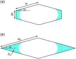 |
| | Fig. 5 Demonstration of the procedure to calculate the s* in case (II). The meniscus position of s* is shown in (a). For a diamond channel a0 = a + b/(2![[thin space (1/6-em)]](https://www.rsc.org/images/entities/char_2009.gif) sin sin![[thin space (1/6-em)]](https://www.rsc.org/images/entities/char_2009.gif) α) (b) with the saturation s⋄*, the position of the meniscus does not change in comparison with (a). α) (b) with the saturation s⋄*, the position of the meniscus does not change in comparison with (a). | |
In Appendix B, we derive an analytic expression of s⋄* for the diamond channel,
| |  | (39) |
we can compute the
s* for case (II) by the simple geometric calculation
where
S0 and
S⋄0 are the total area of the nearly-rectangular cross-section [
Fig. 5(a)] and the diamond cross-section [
Fig. 5(b)], respectively.
S△ is the area of the truncated triangle. This leads to
| |  | (41) |
| |  | (42) |
Similar to case (I), the above expression is constrained by
When α is close to zero (not equal to zero), the trigonometric functions take simple form sin![[thin space (1/6-em)]](https://www.rsc.org/images/entities/char_2009.gif) α ≃ α, tan
α ≃ α, tan![[thin space (1/6-em)]](https://www.rsc.org/images/entities/char_2009.gif) α ≃ α, cos
α ≃ α, cos![[thin space (1/6-em)]](https://www.rsc.org/images/entities/char_2009.gif) α ≃ 1. Using these simplifications, approximated expressions for the diamond and nearly-rectangle can be obtained
α ≃ 1. Using these simplifications, approximated expressions for the diamond and nearly-rectangle can be obtained
| |  | (44) |
| |  | (45) |
For the nearly-rectangular cross-section
(45), the function is a non-monotonic function of
α. We can compute ∂(
s*)
app/∂
α = 0, leading to the extreme point
| |  | (46) |
4.4
s* results
We summarize the results of previous two sections. For a fixed value of β, the coexistence s* can locate either in the range of case (I) with menisci composed of four fingers, or case (II) with two fingers. For the four-finger case (I), the value of s* is given by eqn (36) and the range of s* is 0 < s* < sc1. For the two-finger case (II), the value of s* is given by eqn (42) and the range is sc1 ≤ s* ≤ sc2.
Fig. 6 shows the value of s* as a function of tan![[thin space (1/6-em)]](https://www.rsc.org/images/entities/char_2009.gif) α for different values of β. For the special case of the diamond channel, β = 0, s* is given by eqn (39). This function is plotted with the solid black line in Fig. 6. It is a monotonically decreasing function when tan
α for different values of β. For the special case of the diamond channel, β = 0, s* is given by eqn (39). This function is plotted with the solid black line in Fig. 6. It is a monotonically decreasing function when tan![[thin space (1/6-em)]](https://www.rsc.org/images/entities/char_2009.gif) α increases. Also plotted is the approximated solution eqn (44). The approximated solution has good agreement with the exact formulae at small tan
α increases. Also plotted is the approximated solution eqn (44). The approximated solution has good agreement with the exact formulae at small tan![[thin space (1/6-em)]](https://www.rsc.org/images/entities/char_2009.gif) α, but shows noticeable deviation at large tan
α, but shows noticeable deviation at large tan![[thin space (1/6-em)]](https://www.rsc.org/images/entities/char_2009.gif) α.
α.
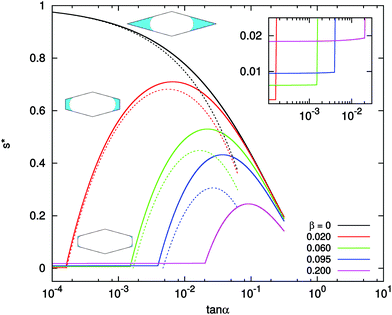 |
| | Fig. 6 The s* value as a function of tan![[thin space (1/6-em)]](https://www.rsc.org/images/entities/char_2009.gif) α and β. The solid lines are exact solutions: black, β = 0, diamond channel, eqn (39); red, β = 0.02, nearly-rectangular channel, eqn (36) and (42); green, β = 0.06; blue, β = 0.095; violet, β = 0.20. The dashed lines are approximated solutions given in eqn (44) and (45). There is no approximated solution for β = 0.20. The inset shows the enlarged part near small tan α and β. The solid lines are exact solutions: black, β = 0, diamond channel, eqn (39); red, β = 0.02, nearly-rectangular channel, eqn (36) and (42); green, β = 0.06; blue, β = 0.095; violet, β = 0.20. The dashed lines are approximated solutions given in eqn (44) and (45). There is no approximated solution for β = 0.20. The inset shows the enlarged part near small tan![[thin space (1/6-em)]](https://www.rsc.org/images/entities/char_2009.gif) α, where the transition from case (I) to case (II) takes place at tan α, where the transition from case (I) to case (II) takes place at tan![[thin space (1/6-em)]](https://www.rsc.org/images/entities/char_2009.gif) αcrit. αcrit. | |
For nearly-rectangular channel, β > 0, representative curves are shown in solid lines in Fig. 6. The value of s* shows two different regions. When tan![[thin space (1/6-em)]](https://www.rsc.org/images/entities/char_2009.gif) α is small, s* corresponds to the four-finger configuration of case (I), and the expression is given in eqn (36). In this case, the value of s* is also very small (see the inset for the absolute values). When tan
α is small, s* corresponds to the four-finger configuration of case (I), and the expression is given in eqn (36). In this case, the value of s* is also very small (see the inset for the absolute values). When tan![[thin space (1/6-em)]](https://www.rsc.org/images/entities/char_2009.gif) α is large, s* is located in the range of case (II) and its expression is given by eqn (42). In this case, the value of s* is large and has a non-monotonic dependence on tan
α is large, s* is located in the range of case (II) and its expression is given by eqn (42). In this case, the value of s* is large and has a non-monotonic dependence on tan![[thin space (1/6-em)]](https://www.rsc.org/images/entities/char_2009.gif) α. We also plot the approximated solution (45) in dashed lines. The agreement between the approximated and exact solutions is good when α is small or β is small.
α. We also plot the approximated solution (45) in dashed lines. The agreement between the approximated and exact solutions is good when α is small or β is small.
The two regions of s* are connected at a critical αcrit value. When β increases, i.e. as the constriction becomes less elongated, the critical α moves to a larger value. This trend is also demonstrated in Fig. 7(a) with the red solid line.
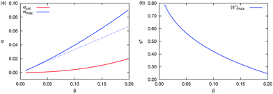 |
| | Fig. 7 (a) The critical value αcrit (red), when the location of s* changes from case (I) to case (II), is plotted as a function of the aspect ratio β. Also shown is the value of αmax at which s* reaches the maximum. The blue solid line is the exact solution and the dashed blue line is the approximated solution (αmax)app = β/3. (b) The maximum value of (s*)max is plotted as a function of β. | |
When s* is located in the range of case (II), the value of s* is very sensitive to α. For example, for β = 0.02 shown as the red line in Fig. 6, s* increases from nearly zero to about 0.7 when tan![[thin space (1/6-em)]](https://www.rsc.org/images/entities/char_2009.gif) α changes from 2 × 10⁻⁴ to 5 × 10⁻³ (less than 0.2° change). In this range, the value s* increases first with increasing tan
α changes from 2 × 10⁻⁴ to 5 × 10⁻³ (less than 0.2° change). In this range, the value s* increases first with increasing tan![[thin space (1/6-em)]](https://www.rsc.org/images/entities/char_2009.gif) α, reaching a maximum, then decreases when tan
α, reaching a maximum, then decreases when tan![[thin space (1/6-em)]](https://www.rsc.org/images/entities/char_2009.gif) α increases further. The location of the maximum αmax increases with increasing β. This is shown as the blue solid line in Fig. 7(a). Also shown is the approximated value (αmax)app = β/3 in dashed line, which again has better agreement with the exact solution at small β. The maximum value of (s*)max is a decreasing function of β, shown in Fig. 7(b). When tan
α increases further. The location of the maximum αmax increases with increasing β. This is shown as the blue solid line in Fig. 7(a). Also shown is the approximated value (αmax)app = β/3 in dashed line, which again has better agreement with the exact solution at small β. The maximum value of (s*)max is a decreasing function of β, shown in Fig. 7(b). When tan![[thin space (1/6-em)]](https://www.rsc.org/images/entities/char_2009.gif) α increases further after passing the maximum, the cross-section of the channel resembles a diamond with two tips removed (small SΔ in Fig. 5). In this case, s* curves of different β values all approach the curve of the diamond channel.
α increases further after passing the maximum, the cross-section of the channel resembles a diamond with two tips removed (small SΔ in Fig. 5). In this case, s* curves of different β values all approach the curve of the diamond channel.
In the experiment of Keita et al.,11 the aspect ratio is β = 0.095 and the deviation from the rectangle tan![[thin space (1/6-em)]](https://www.rsc.org/images/entities/char_2009.gif) α = 0.01. From Fig. 6, we can obtain s* ≃ 0.2987 by eqn (42). This value of s* is located in case (II) and the menisci are composed of two fingers. Our result is consistent with the observation in ref. 11 (see the left column of Fig. 1). The experimental value of s* (at the finger/bulk interface) is about 0.38, which is close to our prediction.
α = 0.01. From Fig. 6, we can obtain s* ≃ 0.2987 by eqn (42). This value of s* is located in case (II) and the menisci are composed of two fingers. Our result is consistent with the observation in ref. 11 (see the left column of Fig. 1). The experimental value of s* (at the finger/bulk interface) is about 0.38, which is close to our prediction.
In the experiment of Seck et al.,12 the aspect ratio is β = 0.2 and the cross-section is nearly perfect rectangle, so α is very small. In this case, Fig. 6 shows that a very small s* exists over a large range of tan![[thin space (1/6-em)]](https://www.rsc.org/images/entities/char_2009.gif) α values, corresponding to case (I) with four fingers. The value of s* given by eqn (36) is s* ≃ 0.018, again this is consistent with the observation in ref. 12 (also see the right column of Fig. 1).
α values, corresponding to case (I) with four fingers. The value of s* given by eqn (36) is s* ≃ 0.018, again this is consistent with the observation in ref. 12 (also see the right column of Fig. 1).
5 Conclusions
In this paper, we studied the wetting phenomenon in a nearly-rectangular channel. In the equilibrium, the channel can be filled by a wetting fluid completely, corresponding to s = 1, or partially filled with s* < 1. The partial-wetting region is composed of either four or two fluid columns (referred to as “finger”). We analyzed different scenarios of wetting behaviors and obtained analytical results of s* as a function of the aspect ratio β and the angle α. We found
(1) When the cross-section is a nearly perfect rectangle, angle α is close to zero, the saturation s* is located in the four-finger region and with a very small value.
(2) When the angle α is large but still less than 1° (tan![[thin space (1/6-em)]](https://www.rsc.org/images/entities/char_2009.gif) 1° = 0.017), the value of s* is very sensitive with respect to even a tiny change of α. The meniscus takes the two-finger configuration. The value of s* can be as large as 0.8, which is significantly larger than that in the four-finger case.
1° = 0.017), the value of s* is very sensitive with respect to even a tiny change of α. The meniscus takes the two-finger configuration. The value of s* can be as large as 0.8, which is significantly larger than that in the four-finger case.
In this work, we have focused on the equilibrium case and discussed about the coexistence between the bulk region and finger region. When the system has a slow dynamics or the capillary number is small, our results of the saturation s* should apply at the interface between the bulk and the finger. We indeed found good agreement with the experimental observations.11,12 For simplicity, we have only discussed the case that the equilibrium contact angle is zero. The extension to a finite contact angle is straightforward. For fully wetting, a precursor film of molecular thickness might exist on the surface. In this case the free energy functions take the same forms, thus our prediction of s* should remain valid. An important and related problem is how the change of s* influences the imbibition dynamics.18–20 We expect that our framework can provide theoretical support to the understanding of the wetting and drying in porous media, and in the design of micro/nanofluidic devices.
Conflicts of interest
There are no conflicts to declare.
A Alternative derivation of s*
In this Appendix, we show that the coexistence condition (32) is equivalent to the geometric condition suggested in ref. 10.
Mason and Morrow used the virtual work balance to derive a condition for the capillary pressure (eqn (4) in ref. 10). Written in our notation, the condition is
| | pc(S0 − S) = γ(PS![[thin space (1/6-em)]](https://www.rsc.org/images/entities/char_2009.gif) cos cos![[thin space (1/6-em)]](https://www.rsc.org/images/entities/char_2009.gif) θE + PL). θE + PL). | (47) |
Here
pc is the capillary pressure.
S0 is the total area of the cross-section, and
S is the area occupied by the fluid.
PS is the solid–vapor perimeter and
PL is the liquid–vapor perimeter.
Using the definition of the capillary pressure (31), we write the LHS of eqn (47)
| |  | (48) |
The free energy densities for the partial saturation and full saturation are
| | | f(s) = (P0 − PS)γSL + PSγSV + PLγ, | (49) |
where
P0 is the length of the perimeter in the cross-section.
γSL,
γSV, and
γ are the interfacial tensions of solid–liquid, solid–vapor, and liquid–vapor interfaces, respectively. From the free energy densities, we calculate
| | f(s) − f(1) = PS(γSV − γSL) + PLγ = PSγ![[thin space (1/6-em)]](https://www.rsc.org/images/entities/char_2009.gif) cos cos![[thin space (1/6-em)]](https://www.rsc.org/images/entities/char_2009.gif) θE + PLγ. θE + PLγ. | (51) |
This is just the RHS of
eqn (47).
Combining eqn (48) and (51), we obtain the same condition (32) for s*
| |  | (52) |
B Diamond channel
In this Appendix, we calculate s* for a channel with a diamond cross-section. The diamond has a side length a0, and the sharp angle formed by the two sides is 2α. To calculate the free energy density f(s), we need to distinguish the two cases shown in Fig. 8.
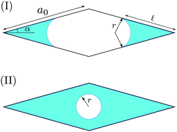 |
| | Fig. 8 Two scenarios of the wetting fluid in the cross-section of a diamond channel. The side length of the diamond is a0 and two adjacent sides form an angle 2α. (I) The liquid–vapor interfaces form two separated arcs in the corners. The radius of curvature of the arc is r and the wetting length on the side is ![[small script l]](https://www.rsc.org/images/entities/char_e146.gif) . (II) The liquid–vapor interface is a full circle of the radius r. . (II) The liquid–vapor interface is a full circle of the radius r. | |
Case (I)
Here the meniscus forms two separate fingers with a radius of curvature r. The fluid covers a length ![[small script l]](https://www.rsc.org/images/entities/char_e146.gif) on the side. These two lengths satisfy the following relationThe area of the fluid is given by
on the side. These two lengths satisfy the following relationThe area of the fluid is given by| |  | (54) |
The total area of the cross-section isThe saturation is then given by| |  | (56) |
Since ![[small script l]](https://www.rsc.org/images/entities/char_e146.gif) ≤ a0, the range of s in case (I) is
≤ a0, the range of s in case (I) is| |  | (57) |
The free energy density is
| | f(s) = (−4 + (2π − 4α)tan![[thin space (1/6-em)]](https://www.rsc.org/images/entities/char_2009.gif) α) α)![[small script l]](https://www.rsc.org/images/entities/char_e146.gif) γ γ | (58) |
| |  | (59) |
with
| |  | (60) |
Case (II)
In this case, the meniscus forms a complete circle with the radius r. The area of the fluid isThe saturation is| |  | (62) |
Since r ≤ a0![[thin space (1/6-em)]](https://www.rsc.org/images/entities/char_2009.gif) sin
sin![[thin space (1/6-em)]](https://www.rsc.org/images/entities/char_2009.gif) α
α![[thin space (1/6-em)]](https://www.rsc.org/images/entities/char_2009.gif) cos
cos![[thin space (1/6-em)]](https://www.rsc.org/images/entities/char_2009.gif) α (the shortest distance from the center to the side), the range of s in case (II) is
α (the shortest distance from the center to the side), the range of s in case (II) is| |  | (63) |
The free energy density is
| |  | (65) |
For the complete saturation, the free energy density is
| |  | (66) |
Calculation of s*
Now we can compute s*. Similar to the case of rectangular cross-section, s⋄* exists only in case (I). We again use condition (32) combined with the free energy functions (59) and (66)| |  | (67) |
| |  | (68) |
The s⋄* is determined by the equation| |  | (69) |
The solution is| |  | (70) |
C Equivalence of coexistent conditions in a diamond channel and a nearly-rectangular channel
Here we show the equivalence of the coexistent conditions in a nearly-rectangular channel [Fig. 5(a)] and a diamond channel [Fig. 5(b)]. We will denote quantities in the diamond channel with a subscript ⋄.
The free energy functions in these two channels are related by
| |  | (71) |
The area occupied by the fluid in two channels are given by
These two equations lead to the following relation
| |  | (73) |
Using the definition of the saturation
s =
S/
S0 and
s⋄ =
S⋄/
S⋄0, we can rewrite
eqn (73) into
| |  | (74) |
From eqn (71) and (72), we see that the free energy and the area for two cases differ only by a constant term, thus
| | | f(1) − f(s) = f⋄(1) − f⋄(s⋄), | (75) |
| | | S0(1 − s) = S⋄0(1 − s⋄). | (76) |
These lead to
| |  | (77) |
When the saturation in the diamond channel satisfies the coexistent condition (32),
| |  | (78) |
we immediately obtain from
eqn (74) and (77) that the corresponding saturation in the nearly-rectangular channel also satisfies the coexistent condition
| |  | (79) |
Acknowledgements
This work was supported by the National Natural Science Foundation of China (NSFC) through the Grant No. 21774004 (J. Z.), 91634202 and 11972212 (Q. S.) M. D. acknowledges the financial support of the Chinese Central Government in the Thousand Talents Program.
Notes and references
-
J. Bear, Dynamics of Fluids in Porous Media, Dover, 1972 Search PubMed.
- P.-G. de Gennes, Rev. Mod. Phys., 1985, 57, 827 CrossRef CAS.
- D. Bonn, J. Eggers, J. Indekeu, J. Meunier and E. Rolley, Rev. Mod. Phys., 2009, 81, 739 CrossRef CAS.
- M. Prat, Int. J. Heat Mass Transfer, 2007, 50, 1455–1468 CrossRef CAS.
- F. Chauvet, P. Duru, S. Geoffroy and M. Prat, Phys. Rev. Lett., 2009, 103, 124502 CrossRef CAS.
- R. P. Mayer and R. A. Stowe, J. Colloid Sci., 1965, 20, 893–911 CrossRef CAS.
- H. M. Princen, J. Colloid Interface Sci., 1969, 30, 69 CrossRef.
- H. M. Princen, J. Colloid Interface Sci., 1969, 30, 359 CrossRef.
- H. M. Princen, J. Colloid Interface Sci., 1970, 34, 171 CrossRef CAS.
- G. Mason and N. R. Morrow, J. Chem. Soc., Faraday Trans. 1, 1984, 80, 2375–2393 RSC.
- E. Keita, S. A. Koehler, P. Faure, D. A. Weitz and P. Coussot, Eur. Phys. J. E: Soft Matter Biol. Phys., 2016, 39, 23 CrossRef.
- M. D. Seck, E. Keita and P. Coussot, Transp. Porous Media, 2018, 128, 915–928 CrossRef.
- M. M. Weislogel, J. A. Baker and R. M. Jenson, J. Fluid Mech., 2011, 685, 271–305 CrossRef.
- M. M. Weislogel, J. Fluid Mech., 2012, 709, 622–647 CrossRef.
- P. Concus and R. Finn, Proc. Natl. Acad. Sci. U. S. A., 1969, 63, 292–299 CrossRef CAS.
- L. H. Tanner, J. Phys. D: Appl. Phys., 1979, 12, 1473–1484 CrossRef CAS.
- M. Dong and I. Chatzis, J. Colloid Interface Sci., 1995, 172, 278–288 CrossRef CAS.
- T. Yu, J. Zhou and M. Doi, Soft Matter, 2018, 14, 9263–9270 RSC.
- T. Yu, Y. Jiang, J. Zhou and M. Doi, Langmuir, 2019, 35, 5183–5190 CrossRef.
- J. Zhou and M. Doi, J. Fluid Mech., 2020, 900, A29 CrossRef CAS.
|
| This journal is © The Royal Society of Chemistry 2021 |
Click here to see how this site uses Cookies. View our privacy policy here.  *bd and
Masao
Doi
b


![[small script l]](https://www.rsc.org/images/entities/char_e146.gif) is the wetting length on the a side. The radius r can be expressed as a function of
is the wetting length on the a side. The radius r can be expressed as a function of ![[small script l]](https://www.rsc.org/images/entities/char_e146.gif)


![[thin space (1/6-em)]](https://www.rsc.org/images/entities/char_2009.gif) cos
cos![[thin space (1/6-em)]](https://www.rsc.org/images/entities/char_2009.gif) αb + 2a
αb + 2a![[thin space (1/6-em)]](https://www.rsc.org/images/entities/char_2009.gif) cos
cos![[thin space (1/6-em)]](https://www.rsc.org/images/entities/char_2009.gif) αa
αa![[thin space (1/6-em)]](https://www.rsc.org/images/entities/char_2009.gif) sin
sin![[thin space (1/6-em)]](https://www.rsc.org/images/entities/char_2009.gif) α = 2a2
α = 2a2![[thin space (1/6-em)]](https://www.rsc.org/images/entities/char_2009.gif) cos
cos![[thin space (1/6-em)]](https://www.rsc.org/images/entities/char_2009.gif) α(sin
α(sin![[thin space (1/6-em)]](https://www.rsc.org/images/entities/char_2009.gif) α + β),
α + β),
![[small script l]](https://www.rsc.org/images/entities/char_e146.gif) is limited by
is limited by ![[small script l]](https://www.rsc.org/images/entities/char_e146.gif) < b/2. This leads to the following constraint on the saturation
< b/2. This leads to the following constraint on the saturation

![[thin space (1/6-em)]](https://www.rsc.org/images/entities/char_2009.gif) cos
cos![[thin space (1/6-em)]](https://www.rsc.org/images/entities/char_2009.gif) θE = γSV − γSL and zero equilibrium contact angle θE = 0. We choose a dried surface as the reference point for the free energy. For the case of total wetting, there might be a precursor film of molecular thickness.2,3,16 The first term in eqn (9) is modified as 8
θE = γSV − γSL and zero equilibrium contact angle θE = 0. We choose a dried surface as the reference point for the free energy. For the case of total wetting, there might be a precursor film of molecular thickness.2,3,16 The first term in eqn (9) is modified as 8![[small script l]](https://www.rsc.org/images/entities/char_e146.gif) (γSL − (γ + γSL)), and the final expression remains valid.
(γSL − (γ + γSL)), and the final expression remains valid.


![[small script l]](https://www.rsc.org/images/entities/char_e146.gif) as
as

![[small script l]](https://www.rsc.org/images/entities/char_e146.gif) ,
,
![[small script l]](https://www.rsc.org/images/entities/char_e146.gif) < a,
< a,


![[small script l]](https://www.rsc.org/images/entities/char_e146.gif) as an intermediate variable. The range of
as an intermediate variable. The range of ![[small script l]](https://www.rsc.org/images/entities/char_e146.gif) is b/2 ≤
is b/2 ≤ ![[small script l]](https://www.rsc.org/images/entities/char_e146.gif) < a, leading to the two bounds sc1 and sc2 for the saturation. The saturation and the free energy density as functions of
< a, leading to the two bounds sc1 and sc2 for the saturation. The saturation and the free energy density as functions of ![[small script l]](https://www.rsc.org/images/entities/char_e146.gif) are given by eqn (14) and (18), respectively.
are given by eqn (14) and (18), respectively.


![[thin space (1/6-em)]](https://www.rsc.org/images/entities/char_2009.gif) α = 0.002 and 0.1, respectively. The aspect ratio β takes the value in experiments of ref. 11.
α = 0.002 and 0.1, respectively. The aspect ratio β takes the value in experiments of ref. 11.

![[thin space (1/6-em)]](https://www.rsc.org/images/entities/char_2009.gif) α = 0.002. (b) tan
α = 0.002. (b) tan![[thin space (1/6-em)]](https://www.rsc.org/images/entities/char_2009.gif) α = 0.1. The different colors of the curves correspond to the three cases [red (I), green (II), and blue (III)]. The coexistence conditions of (32) are shown with gray lines. (c) and (d) The function g(s) [eqn (33)] corresponding to (a) and (b). In (c), s* locates in case (I) and in (d), s* locates in case (II).
α = 0.1. The different colors of the curves correspond to the three cases [red (I), green (II), and blue (III)]. The coexistence conditions of (32) are shown with gray lines. (c) and (d) The function g(s) [eqn (33)] corresponding to (a) and (b). In (c), s* locates in case (I) and in (d), s* locates in case (II).![[script L]](https://www.rsc.org/images/entities/char_e144.gif) with respect to the fraction ϕ and the saturation s
with respect to the fraction ϕ and the saturation s![[script L]](https://www.rsc.org/images/entities/char_e144.gif) = Ftotal + pc(LϕS0s + L(1 − ϕ)S0 − Vl)
= Ftotal + pc(LϕS0s + L(1 − ϕ)S0 − Vl)


 with F3 > 0. The second derivative f′′(s) < 0, so s* cannot exist in the range of case (III). We will discuss two cases that either s* is located in case (I) or case (II).


 is always satisfied. Thus, for the rectangular cross-section, s* is always present in case (I) with four fingers.
![[small script l]](https://www.rsc.org/images/entities/char_e146.gif) . The direct calculation of f′(s) is cumbersome and leads to a complicated expression of s*. Here we present a simpler derivation. Consider a diamond channel that is similar to the case (II) we are interested in. In Fig. 5(a), the position of the meniscus corresponds to the s*. It is easy to show that the same position of the meniscus in a diamond channel with a0 = a + b/(2
. The direct calculation of f′(s) is cumbersome and leads to a complicated expression of s*. Here we present a simpler derivation. Consider a diamond channel that is similar to the case (II) we are interested in. In Fig. 5(a), the position of the meniscus corresponds to the s*. It is easy to show that the same position of the meniscus in a diamond channel with a0 = a + b/(2![[thin space (1/6-em)]](https://www.rsc.org/images/entities/char_2009.gif) sin
sin![[thin space (1/6-em)]](https://www.rsc.org/images/entities/char_2009.gif) α), shown in Fig. 5(b), will also correspond to the s⋄* for the diamond channel.
α), shown in Fig. 5(b), will also correspond to the s⋄* for the diamond channel.


![[thin space (1/6-em)]](https://www.rsc.org/images/entities/char_2009.gif) α ≃ α, tan
α ≃ α, tan![[thin space (1/6-em)]](https://www.rsc.org/images/entities/char_2009.gif) α ≃ α, cos
α ≃ α, cos![[thin space (1/6-em)]](https://www.rsc.org/images/entities/char_2009.gif) α ≃ 1. Using these simplifications, approximated expressions for the diamond and nearly-rectangle can be obtained
α ≃ 1. Using these simplifications, approximated expressions for the diamond and nearly-rectangle can be obtained


![[thin space (1/6-em)]](https://www.rsc.org/images/entities/char_2009.gif) α for different values of β. For the special case of the diamond channel, β = 0, s* is given by eqn (39). This function is plotted with the solid black line in Fig. 6. It is a monotonically decreasing function when tan
α for different values of β. For the special case of the diamond channel, β = 0, s* is given by eqn (39). This function is plotted with the solid black line in Fig. 6. It is a monotonically decreasing function when tan![[thin space (1/6-em)]](https://www.rsc.org/images/entities/char_2009.gif) α increases. Also plotted is the approximated solution eqn (44). The approximated solution has good agreement with the exact formulae at small tan
α increases. Also plotted is the approximated solution eqn (44). The approximated solution has good agreement with the exact formulae at small tan![[thin space (1/6-em)]](https://www.rsc.org/images/entities/char_2009.gif) α, but shows noticeable deviation at large tan
α, but shows noticeable deviation at large tan![[thin space (1/6-em)]](https://www.rsc.org/images/entities/char_2009.gif) α.
α.
![[thin space (1/6-em)]](https://www.rsc.org/images/entities/char_2009.gif) α and β. The solid lines are exact solutions: black, β = 0, diamond channel, eqn (39); red, β = 0.02, nearly-rectangular channel, eqn (36) and (42); green, β = 0.06; blue, β = 0.095; violet, β = 0.20. The dashed lines are approximated solutions given in eqn (44) and (45). There is no approximated solution for β = 0.20. The inset shows the enlarged part near small tan
α and β. The solid lines are exact solutions: black, β = 0, diamond channel, eqn (39); red, β = 0.02, nearly-rectangular channel, eqn (36) and (42); green, β = 0.06; blue, β = 0.095; violet, β = 0.20. The dashed lines are approximated solutions given in eqn (44) and (45). There is no approximated solution for β = 0.20. The inset shows the enlarged part near small tan![[thin space (1/6-em)]](https://www.rsc.org/images/entities/char_2009.gif) α, where the transition from case (I) to case (II) takes place at tan
α, where the transition from case (I) to case (II) takes place at tan![[thin space (1/6-em)]](https://www.rsc.org/images/entities/char_2009.gif) αcrit.
αcrit.![[thin space (1/6-em)]](https://www.rsc.org/images/entities/char_2009.gif) α is small, s* corresponds to the four-finger configuration of case (I), and the expression is given in eqn (36). In this case, the value of s* is also very small (see the inset for the absolute values). When tan
α is small, s* corresponds to the four-finger configuration of case (I), and the expression is given in eqn (36). In this case, the value of s* is also very small (see the inset for the absolute values). When tan![[thin space (1/6-em)]](https://www.rsc.org/images/entities/char_2009.gif) α is large, s* is located in the range of case (II) and its expression is given by eqn (42). In this case, the value of s* is large and has a non-monotonic dependence on tan
α is large, s* is located in the range of case (II) and its expression is given by eqn (42). In this case, the value of s* is large and has a non-monotonic dependence on tan![[thin space (1/6-em)]](https://www.rsc.org/images/entities/char_2009.gif) α. We also plot the approximated solution (45) in dashed lines. The agreement between the approximated and exact solutions is good when α is small or β is small.
α. We also plot the approximated solution (45) in dashed lines. The agreement between the approximated and exact solutions is good when α is small or β is small.![[thin space (1/6-em)]](https://www.rsc.org/images/entities/char_2009.gif) α changes from 2 × 10⁻⁴ to 5 × 10⁻³ (less than 0.2° change). In this range, the value s* increases first with increasing tan
α changes from 2 × 10⁻⁴ to 5 × 10⁻³ (less than 0.2° change). In this range, the value s* increases first with increasing tan![[thin space (1/6-em)]](https://www.rsc.org/images/entities/char_2009.gif) α, reaching a maximum, then decreases when tan
α, reaching a maximum, then decreases when tan![[thin space (1/6-em)]](https://www.rsc.org/images/entities/char_2009.gif) α increases further. The location of the maximum αmax increases with increasing β. This is shown as the blue solid line in Fig. 7(a). Also shown is the approximated value (αmax)app = β/3 in dashed line, which again has better agreement with the exact solution at small β. The maximum value of (s*)max is a decreasing function of β, shown in Fig. 7(b). When tan
α increases further. The location of the maximum αmax increases with increasing β. This is shown as the blue solid line in Fig. 7(a). Also shown is the approximated value (αmax)app = β/3 in dashed line, which again has better agreement with the exact solution at small β. The maximum value of (s*)max is a decreasing function of β, shown in Fig. 7(b). When tan![[thin space (1/6-em)]](https://www.rsc.org/images/entities/char_2009.gif) α increases further after passing the maximum, the cross-section of the channel resembles a diamond with two tips removed (small SΔ in Fig. 5). In this case, s* curves of different β values all approach the curve of the diamond channel.
α increases further after passing the maximum, the cross-section of the channel resembles a diamond with two tips removed (small SΔ in Fig. 5). In this case, s* curves of different β values all approach the curve of the diamond channel.![[thin space (1/6-em)]](https://www.rsc.org/images/entities/char_2009.gif) α = 0.01. From Fig. 6, we can obtain s* ≃ 0.2987 by eqn (42). This value of s* is located in case (II) and the menisci are composed of two fingers. Our result is consistent with the observation in ref. 11 (see the left column of Fig. 1). The experimental value of s* (at the finger/bulk interface) is about 0.38, which is close to our prediction.
α = 0.01. From Fig. 6, we can obtain s* ≃ 0.2987 by eqn (42). This value of s* is located in case (II) and the menisci are composed of two fingers. Our result is consistent with the observation in ref. 11 (see the left column of Fig. 1). The experimental value of s* (at the finger/bulk interface) is about 0.38, which is close to our prediction.![[thin space (1/6-em)]](https://www.rsc.org/images/entities/char_2009.gif) α values, corresponding to case (I) with four fingers. The value of s* given by eqn (36) is s* ≃ 0.018, again this is consistent with the observation in ref. 12 (also see the right column of Fig. 1).
α values, corresponding to case (I) with four fingers. The value of s* given by eqn (36) is s* ≃ 0.018, again this is consistent with the observation in ref. 12 (also see the right column of Fig. 1).![[thin space (1/6-em)]](https://www.rsc.org/images/entities/char_2009.gif) 1° = 0.017), the value of s* is very sensitive with respect to even a tiny change of α. The meniscus takes the two-finger configuration. The value of s* can be as large as 0.8, which is significantly larger than that in the four-finger case.
1° = 0.017), the value of s* is very sensitive with respect to even a tiny change of α. The meniscus takes the two-finger configuration. The value of s* can be as large as 0.8, which is significantly larger than that in the four-finger case.![[thin space (1/6-em)]](https://www.rsc.org/images/entities/char_2009.gif) cos
cos![[thin space (1/6-em)]](https://www.rsc.org/images/entities/char_2009.gif) θE + PL).
θE + PL).
![[thin space (1/6-em)]](https://www.rsc.org/images/entities/char_2009.gif) cos
cos![[thin space (1/6-em)]](https://www.rsc.org/images/entities/char_2009.gif) θE + PLγ.
θE + PLγ.
![[small script l]](https://www.rsc.org/images/entities/char_e146.gif) on the side. These two lengths satisfy the following relation
on the side. These two lengths satisfy the following relation![[small script l]](https://www.rsc.org/images/entities/char_e146.gif)
![[thin space (1/6-em)]](https://www.rsc.org/images/entities/char_2009.gif) tan
tan![[thin space (1/6-em)]](https://www.rsc.org/images/entities/char_2009.gif) α.
α.
![[thin space (1/6-em)]](https://www.rsc.org/images/entities/char_2009.gif) sin
sin![[thin space (1/6-em)]](https://www.rsc.org/images/entities/char_2009.gif) α
α![[thin space (1/6-em)]](https://www.rsc.org/images/entities/char_2009.gif) cos
cos![[thin space (1/6-em)]](https://www.rsc.org/images/entities/char_2009.gif) α.
α.
![[small script l]](https://www.rsc.org/images/entities/char_e146.gif) ≤ a0, the range of s in case (I) is
≤ a0, the range of s in case (I) is
![[thin space (1/6-em)]](https://www.rsc.org/images/entities/char_2009.gif) α)
α)![[small script l]](https://www.rsc.org/images/entities/char_e146.gif) γ
γ


![[thin space (1/6-em)]](https://www.rsc.org/images/entities/char_2009.gif) sin
sin![[thin space (1/6-em)]](https://www.rsc.org/images/entities/char_2009.gif) α
α![[thin space (1/6-em)]](https://www.rsc.org/images/entities/char_2009.gif) cos
cos![[thin space (1/6-em)]](https://www.rsc.org/images/entities/char_2009.gif) α (the shortest distance from the center to the side), the range of s in case (II) is
α (the shortest distance from the center to the side), the range of s in case (II) is


