 Open Access Article
Creative Commons Attribution 3.0 Unported Licence
Electrocatalytic hydrogen production by dinuclear cobalt(II) compounds containing redox-active diamidate ligands: a combined experimental and theoretical study†
Michael G.
Papanikolaou‡
a,
Alexander
Elliott‡
b,
James
McAllister‡
b,
John K.
Gallos
*c,
Anastasios D.
Keramidas
 *d,
Themistoklis A.
Kabanos
 *a,
Stephen
Sproules
 *b and
Haralampos N.
Miras
 *b
*b
aSection of Inorganic and Analytical Chemistry, University of Ioannina, Ioannina 45110, Greece. E-mail: tkampano@uoi.gr
bWest CHEM, School of Chemistry, University of Glasgow, Glasgow G12 8QQ, UK. E-mail: stephen.sproules@glasgow.ac.uk; charalampos.moiras@glasgow.ac.uk
cDepartment of Chemistry, Aristotle University of Thessaloniki, Thessaloniki GR 541 24, Greece. E-mail: igallos@chem.auth.gr
dDepartment of Chemistry, University of Cyprus, Nicosia 2109, Cyprus. E-mail: akeramid@ucy.ac.cy
First published on 28th October 2020
Abstract
The chiral dicobalt(II) complex [CoII2(μ2-L)2] (1) (H2L = N2,N6-di(quinolin-8-yl)pyridine-2,6-dicarboxamide) and its tert-butyl analogue [CoII2(μ2-LBu)2] (2) were synthesized and structurally characterized. Addition of one equivalent of AgSbF6 to the dichloromethane solution of 1 and 2 resulted in the isolation of the mixed-valent dicobalt(III,II) species [CoIIICoII(μ2-L)2]SbF6 (3) and [CoIIICoII(μ2-LBu)2]SbF6 (4). Homovalent 1 and 2 exhibited catalytic activity towards proton reduction in the presence of acetic acid (AcOH) as the substrate. The complexes are stable in solution while their catalytic turnover frequency is estimated at 10 and 34.6 h−1 molcat−1 for 1 and 2, respectively. Calculations reveal one-electron reduction of 1 is ligand-based, preserving the dicobalt(II) core and activating the ligand toward protonation at the quinoline group. This creates a vacant coordination site that is subsequently protonated to generate the catalytically ubiquitous Co(III) hydride. The dinuclear structure persists throughout where the distal Co(II) ion modulates the reactivity of the adjacent metal site by promoting ligand redox activity through spin state switching.
Introduction
With the increasing importance of anthropogenic climate change, the utilization of renewable energy sources is key to solving the upcoming energy crisis. In recent years, the conversion of solar energy into electrical power, with the use of photovoltaics appears to be one of the most promising energy technologies. However, the availability of sunlight does not correlate with the worldwide energy demand. To overcome this obstacle, the storage of excess energy generated via chemical bonds has been proposed.1 The hydrogen evolution reaction (HER) stores energy within the H2 molecule. Its subsequent oxidation releases energy, with water as the only by-product, making hydrogen an important candidate as an environmentally friendly fuel.One strategy for the capture of solar energy as dihydrogen is the use of electrocatalysts driven by photovoltaics. The most efficient hydrogen evolution catalyst to date is platinum, which exhibits fast kinetics at low overpotential.2 However, the scarcity and prohibitive cost of platinum limits its use at a larger scale.3 Hence, a number of catalysts made from earth-abundant elements have been synthesized in order to improve the economic viability of such an electrocatalytic system.4 A wide variety of cobalt complexes has been reported as dihydrogen evolution catalysts, typically based on monomeric cobalt coordinated in a square-planar fashion by multidentate ligands.5–7 In particular, species inspired by the cobalt-containing vitamin B12, known as cobaloximes, have been thoroughly investigated.8–10 Cobaloximes appear to be one of the most active electrocatalysts with high turnover frequency and low overpotential requirements according to recent benchmarking experiments.11
Although not unheard of, dinuclear cobalt complexes are comparatively rare.12,13 The presence of multiple metal centers can aid a homolytic reaction pathway in which adjacent CoIII–H units dissociate to give hydrogen radicals H˙ which subsequently combine to produce H2.14 This reaction pathway requires two metal centers in close proximity, which is possible for monomeric units in homogenous solution, but in a fully realized device in which the catalyst is grafted onto a solid substrate this reaction pathway would be available only in dinuclear catalysts. Although the full catalytic cycle varies for different systems, nearly all involve formation of a CoIII–H via protonation of a low-valent Co center.5,8 However, recent studies have shown that ligand-assisted and ligand-centered mechanistic pathways significantly improve the kinetics and lower the overpotential of the HER by obviating the need the generate an electron rich Co ion.15–17 In such mechanisms, the protonation occurs at the ligand,18–21 and the protons subsequently interact with a metal-hydride to release H2. Furthermore, it has been shown that redox non-innocent ligands participate in the H2 evolution pathways of various metal complexes, by contributing both protons and electrons.22 As a result, it is evident that the fine-tuning of the ligand can further enhance the catalytic activity of metal complexes.
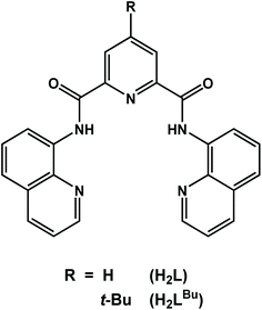
Herein, we describe the synthesis, physicochemical and structural characterization, and electrocatalytic H2 production of two dicobalt(II) complexes with the redox-active ligands N2,N6-di(quinolin-8-yl)pyridine-2,6-dicarboxamide (H2L),20,21 and its tert-butyl analogue (H2LBu) shown in Scheme 1. The electron-releasing tert-butyl group has been incorporated into the 4-position of the pyridine moiety in the multidentate ligand in order to investigate the structure–function relationship. Such ligand modifications have been shown to have significant effect on the catalytic performance.23 The ligands (L)2− and (LBu)2− form dinuclear complexes with cobalt that show effective catalytic behavior in dihydrogen production using acetic acid (AcOH) in N,N-dimethylformamide (DMF) containing 5% (v/v) water. The relevant mechanistic details of H2 evolution reactions and the role of the redox-active ligand are also explored by means of a computational approach based on density functional theory (DFT). The dinuclear structure of 1 is preserved through each step of the proposed mechanism, where proton reduction is hosted by one cobalt center with the reactivity modulating by spin transition at the adjacent cobalt ion that serves to stabilize and promote ligand-based redox chemistry.
Experimental section
General methods
Synthesis of all complexes was performed under an inert atmosphere using standard Schlenk techniques. The ligand N2,N6-di(quinolin-8-yl)pyridine-2,6-dicarboxamide (H2L), and complex [Zn2(μ2-L)2] (5) were synthesized following published procedures.24 All other chemicals were obtained commercially and used without further purification. Dichloromethane and n-heptane were dried over calcium hydride and sodium, respectively, and distilled prior to use. 1H NMR spectra of the organic molecules were recorded on a Bruker Avance 300 spectrometer at 300 MHz. Solid state magnetic susceptibilities were measured using a magnetic balance based on the Gouy method. Data were corrected for the intrinsic underlying diamagnetism of the sample using Pascal's constants.25 Merck silica gel 60 F254 TLC plates were used for thin layer chromatography. Elemental analyses were determined by the microanalysis services of the School of Chemistry in Glasgow, using an EA 1110 CHNS, CE-440 Elemental Analyzer.Synthesis of 4-tert-butylpyridine-2,6-dicarboxylic acid
A 250 mL Schlenk flask charged with 2,6-dimethylpyridine (2.00 mL, 17.3 mmol) dissolved in n-heptane (50 mL) was cooled to −80 °C using an ethyl acetate/liquid nitrogen bath. The chilled solution was treated dropwise with tert-butyllithium (1.6 M in hexanes, 27.0 mL, 43.2 mmol) with vigorous stirring. The volatiles were distilled off under vacuum and the mixture was refluxed for 3 h, before the reaction mixture was cooled to 0 °C and quenched by carefully adding 20 mL of 2-propanol followed by 40 mL of water. The aqueous layer was extracted with hexanes (3 × 30 mL), and the combined organic layers were dried over MgSO4 and evaporated to dryness. The residue was reconstituted in water (100 mL), treated with KMnO4 (11.1 g, 70.2 mmol) and refluxed for 24 h, after which the mixture was filtered hot to remove the insoluble brown MnO2. The filtrate was concentrated to 10 mL and its pH was adjusted to 4 by the addition of aqueous HCl (4 M). The colorless precipitate that evolved was collected by filtration, washed with ice-cold water (5 mL) and dried under vacuum (2.12 g, 55%). Anal. calcd for C11H13NO4: C, 59.19; H, 5.87; N, 6.27. Found: C, 59.23; H, 5.80; N, 6.32. Mp = 290 °C. Rf = 0.22 (4![[thin space (1/6-em)]](https://www.rsc.org/images/entities/char_2009.gif) :
:![[thin space (1/6-em)]](https://www.rsc.org/images/entities/char_2009.gif) 1 CHCl3/hexanes).1H NMR (D2O, 300 MHz): δ = 8.45 (s, 2H), 1.43 (s, 9H).
1 CHCl3/hexanes).1H NMR (D2O, 300 MHz): δ = 8.45 (s, 2H), 1.43 (s, 9H).
4-(tert-Butyl)-N2,N6-di(quinolin-8-yl)pyridine-2,6-dicarboxamide (H2LBu)
To a stirred solution of 4-tert-butylpyridine-2,6-dicaboxylic acid (1.00 g, 4.48 mmol) in pyridine (20 mL) was added 8-aminoquinoline (1.29 g, 8.96 mmol) and triphenylphosphite (2.36 mL, 8.96 mmol), and the mixture was refluxed overnight. The resultant yellow solution was cooled to room temperature and the solvent removed under reduced pressure. The colorless residue was triturated with cold ethanol (10 mL), and the solid was collected by filtration, washed with cold ethanol (2 × 5 mL) and diethyl ether (2 × 5 mL), and dried under vacuum (1.70 g, 80%).Anal. calcd for C29H25N5O2: C, 73.25; H, 5.30; N, 14.73. Found: C, 73.32; H, 5.28; N, 14.84. Mp = 272 °C. Rf = 0.20 (4![[thin space (1/6-em)]](https://www.rsc.org/images/entities/char_2009.gif) :
:![[thin space (1/6-em)]](https://www.rsc.org/images/entities/char_2009.gif) 1 CHCl3/hexanes). 1H NMR (D2O, 300 MHz): δ = 12.38 (s, 2H), 9.04–9.01 (dd, 2H), 8.59 (s, 2H), 8.28 (dd, 2H), 8.20 (dd, 2H), 7.67–7.70 (m, 4H), 7.35–7.31 (m, 2H), 1.47 (s, 9H) (Fig. S3†). ESI(+) HRMS: calcd for [M + H]+: m/z 476.2081. Found: 476.2065 (100%).
1 CHCl3/hexanes). 1H NMR (D2O, 300 MHz): δ = 12.38 (s, 2H), 9.04–9.01 (dd, 2H), 8.59 (s, 2H), 8.28 (dd, 2H), 8.20 (dd, 2H), 7.67–7.70 (m, 4H), 7.35–7.31 (m, 2H), 1.47 (s, 9H) (Fig. S3†). ESI(+) HRMS: calcd for [M + H]+: m/z 476.2081. Found: 476.2065 (100%).
Synthesis of bis[μ2-N2,N6-di(quinolin-8-yl)pyridine-2,6-dicarboxamido]dicobalt(II), [Co2(μ2-L)2] (1)
To an ethanol (20 mL) solution of Co(OAc)2·4H2O (0.149 g, 0.60 mmol) was added H2L (0.250 g, 0.6 mmol) and the mixture was refluxed overnight. The pink color of the solution changed slowly to brown and a brown precipitate was formed. The resulting mixture was first cooled to room temperature and then to 2 °C. The precipitate was collected by filtration, washed with cold ethanol (2 × 3 mL) and diethyl ether (2 × 5 mL), and dried under vacuum. Yield = 0.225 g (79%).Anal. calcd for Co2C50H30N10O4: C, 61.86; H, 3.32; N, 14.43. Found: C, 61.42; H, 3.47; N, 14.24. ESI(+) HRMS: calcd for [M]+: m/z 952.1110. Found: 952.1104 (100%). UV-vis (DMF): λ/nm (ε/103 M−1 cm−1): 305 (sh, 19.3), 388 (18.5), 498 (sh, 4.88).
Synthesis of bis[μ2-4-(tert-butyl)-N2,N6-di(quinolin-8-yl)pyridine-2,6-dicarboxamido]di-cobalt(II), [Co2(μ2-LBu)2] (2)
This compound was synthesized following the procedure for 1 using H2LBu (0.173 g, 62%). Yield = 0.173 g (62%).Anal. calcd for Co2C58H46N10O4: C, 65.42; H, 4.35; N, 13.15. Found: C, 65.45; H, 4.47; N, 13.21. ESI(+) HRMS: calcd for [M]+: m/z 1064.2396. Found: 1064.2345 (100%). UV-vis (DMF): λ/nm (ε/103 M−1 cm−1): 308 (sh, 16.6), 381 (17.2), 494 (sh, 2.54).
Synthesis of bis[μ2-N2,N6-di(quinolin-8-yl)pyridine-2,6-dicarboxamido]dicobalt(III/II) hexafluoroantimonate, [CoIIICoII(μ2-L)2]SbF6 (3)
A CH2Cl2 (15 mL) solution of 1 (100 mg, 0.11 mmol) was treated with AgSbF6 (36 mg, 0.11 mmol) and the mixture was stirred at ambient temperature overnight whereupon the color became dark brown. The solution was filtered and then concentrated to ca. 3 mL under reduced pressure. Dropwise addition of diethyl ether (15 mL) afforded a dark brown precipitate, which was collected by filtration, washed with diethyl ether (2 × 5 mL) and dried under vacuum. Yield = 62 mg (50%).Anal. calcd for Co2C50H30N10O4SbF6: C, 50.53; H, 2.54; N, 11.79. Found: C, 50.43; H, 2.89; N, 11.21. ESI(+) HRMS: calcd for [M]+: m/z 952.1110. Found: 952.1111 (100%). UV-vis (DMF): λ/nm (ε/103 M−1 cm−1): 322 (15.3), 387 (17.9), 493 (sh, 2.11), 608 (sh, 0.66).
Synthesis of bis[μ2-4-(tert-butyl)-N2,N6-di(quinolin-8-yl)pyridine-2,6-dicarboxamido]-dicobalt(III/II) hexafluoroantimonate, [CoIIICoII(μ2-LBu)2]SbF6 (4)
This compound was synthesized following the procedure for 3 starting from 2. Yield = 64 mg (52%).Anal. calcd for Co2C58H46N10O4SbF6 (Mr = 1300.69) C, 53.56; H, 3.56; N, 10.77. Found: C, 53.15; H, 3.73; N, 10.02. ESI(+) HRMS: calcd for [M]+: m/z 1064.2396. Found: 1064.2345 (100%). UV-vis (DMF): λ/nm ((ε/103 M−1 cm−1): 317 (12.7), 384 (17.4), 515 (sh, 1.29), 610 (sh, 0.87).
X-ray crystallographic data collection and structure refinement
Suitable single crystal was selected and mounted onto a rubber loop using Fomblin oil. Single-crystal X-ray diffraction data of 1–4 were recorded on a Bruker Apex CCD diffractometer (λ (MoKα) = 0.71073 Å) at 150 K equipped with a graphite monochromator. Structure solution and refinement were carried out with SHELXS-9726 and SHELXL-9727 using the WinGX software package.28 Data collection and reduction were performed using the Apex2 software package. Corrections for incident and diffracted beam absorption effects were applied using empirical absorption corrections.29 All the non-H atoms were refined anisotropically. The positions of hydrogen atoms were calculated based on stereochemical considerations using the riding model. Final unit cell data and refinement statistics are collated in Table 1.| 1·2CHCl3 | 2 | 3·3CH2Cl2 | 4·1.75CH2Cl2 | |
|---|---|---|---|---|
| a R 1 = ∑||Fo| − |Fc||/∑|Fo|. b wR2 = {∑[w(Fo2 − Fc2)2]/∑[w(Fo2)2]}1/2, where w = 1/[σ2(Fo2) + (aP)2 + bP], P = (Fo2 + 2Fc2)/3. c GoF = {∑[w(Fo2 − Fc2)2]/(n − p)}1/2, where n = number of reflections and p is the total number of parameters refined. | ||||
| Formula | C52H32Cl6Co2N10O4 | C58H46Co2N10O4 | C53H36Cl6Co2F6N10O4Sb | C127.61H117.06Cl7.06Co4F12N20O11Sb2 |
| M r/g mol−1 | 1191.44 | 1064.91 | 1443.24 | 3063.85 |
| T/K | 150(2) | 150(2) | 150(2) | 150(2) |
| Symmetry | Hexagonal | Monoclinic | Monoclinic | Triclinic |
| Space group | P64 | P21/c | P21/c |
P![[1 with combining macron]](https://www.rsc.org/images/entities/char_0031_0304.gif) |
| a/Å | 18.412(3) | 21.807(7) | 14.5650(5) | 14.7291(3) |
| b/Å | 18.412(3) | 12.592(4) | 13.4841(5) | 17.3069(5) |
| c/Å | 13.362(3) | 18.006(5) | 27.7621(9) | 28.5952(5) |
| α/° | 90 | 90 | 90 | 94.357(2) |
| β/° | 90 | 103.952(4) | 103.074(3) | 98.039(2) |
| γ/° | 120 | 90 | 90 | 115.043(2) |
| ρ calcd/μg m−3 | 1.513 | 1.474 | 1.805 | 1.574 |
| V/Å3 | 3923(2) | 4799(3) | 5311.0(3) | 6464.5(3) |
| Z | 3 | 4 | 4 | 2 |
| μ/mm−1 | 0.997 | 0.754 | 1.504 | 1.144 |
| F (000) | 1806.0 | 2200 | 2868.0 | 3093.0 |
| R 1 | 0.043 | 0.056 | 0.036 | 0.082 |
| wR2b | 0.076 | 0.1642 | 0.090 | 0.208 |
| GoF, Sc | 0.804 | 1.052 | 1.059 | 1.115 |
Electrochemistry
Electrochemical measurements were performed under Ar atmosphere, at room temperature, in DMF with 5% (v/v) H2O containing 0.1 M [N(n-Bu)4]ClO4 as a supporting electrolyte, and 1 mM of the complex. The scan rate was 100 mV s−1 unless otherwise stated. The working electrode was a glassy carbon electrode, platinum wire counter electrode and saturated calomel electrode (SCE) as reference (E = +0.244 V) and under these conditions, the Cp2Fe+/Cp2Fe couple consistently occurred at +0.470 V. The potential values are reported against NHE throughout the manuscript.30 The cell was filled with 25 mL of the catalytic mixture and degassed with Ar for 10 min. A blank was prepared containing only 0.1 M supporting electrolyte in degassed solvent. Table 2 presents the control experiments along with the catalytic runs in the presence of the utilized concentrations of AcOH. The calculated electrocatalytic performance parameters are determined based on established definition and methodology.11,31 Simulations were performed using the open source program CVsim.32| Experiment | [1]/mM | AcOH/μL | AcOH equiv. |
|---|---|---|---|
| Blank 1 | 0 | 0 | 0 |
| Blank 2 | 0 | 57.3 | 30 |
| 1 | 0.1 | 1.91 | 1 |
| 2 | 0.1 | 4.78 | 2.5 |
| 3 | 0.1 | 9.55 | 5 |
| 4 | 0.1 | 14.3 | 7.5 |
| 5 | 0.1 | 19.1 | 10 |
| 6 | 0.1 | 23.9 | 12.5 |
| 7 | 0.1 | 28.7 | 15 |
| 8 | 0.1 | 38.2 | 20 |
| 9 | 0.1 | 47.8 | 25 |
| 10 | 0.1 | 57.3 | 30 |
Gas chromatography (GC)
GC was used to confirm that the measured currents correspond to the reduction of protons to hydrogen using an Agilent GC 7890 A with a thermal conductivity detector. The GC system was calibrated using certified standards of hydrogen at various concentrations (vol %) in Ar (CK Gas Limited, UK) before use. The faradaic efficiency measurements were recorded using a single airtight cell after degassing with Ar. Bulk electrolysis was performed at −1.8 V vs. SCE was applied to the system. The headspace was sampled (25 μL) and injected directly into the GC at appropriate time intervals. The faradaic efficiency was calculated by the ratio of expected H2 (%) in the headspace (as calculated from the charged passed) to H2 (%) detected using GC.Results and discussion
Synthesis of the ligands and complexes
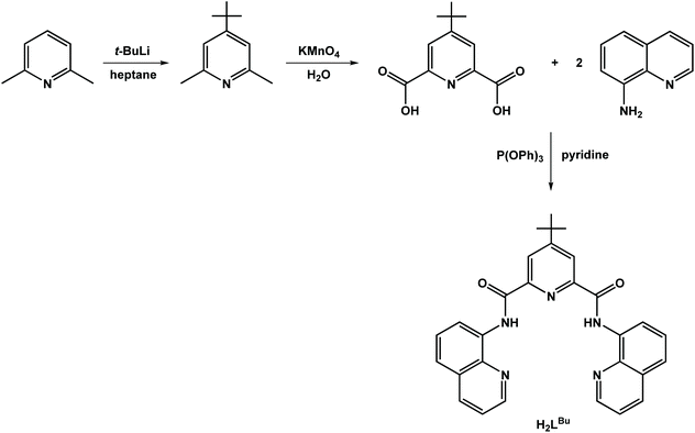
The ligands used in this study are depicted in Scheme 1. The ligand, H2L, was synthesized by condensing 8-aminoquinoline with 2,6-pyridinedicarboxylic acid in the presence of pyridine and triphenylphosphite as previously described.24 This procedure was applied to the preparation of the tert-butyl analogue, H2LBu, following the two-step process beginning with alkylation of 2,6-dimethylpyridine with tert-butyllithium,33 and then subsequent oxidation to give 4-tert-butylpyridine-2,6-dicarboxylic acid (Scheme 2).The dicobalt compounds 1 and 2 were synthesized in high yield by refluxing the diamidate ligands with an equimolar amount of cobalt(II) acetate in ethanol. The dicobalt species are readily oxidized with an equivalent of a silver salt to give dark brown, mixed-valent CoIIICoII complexes, 3 and 4. The composition of compound 1–4 was confirmed by microanalysis, high-resolution mass spectrometry (HRMS) and single-crystal X-ray diffractometry.
Crystal structures
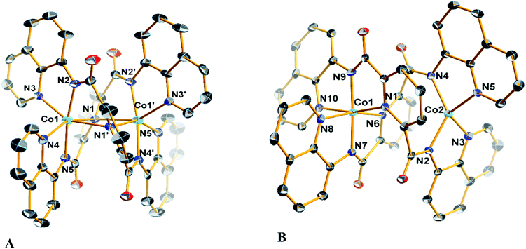
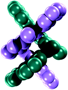
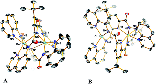
Diffraction quality single crystals of 1–4 were grown by slow diffusion of diethyl ether into a saturated dichloromethane or chloroform solution of the complex. Selected bond lengths and angles are listed in Tables S1 and S2.† The molecular structure of the binuclear cobalt(II) complex 1·2CHCl3 is depicted in Fig. 1. The Co(II) ions in the binuclear complex 1 are coordinated to two amide N atoms at 2.021(8) and 2.009(1) Å, two quinoline N atoms at 2.110(8) and 2.012(1) Å and two pyridine N atoms at 2.401(8) and 2.42(1) Å from two L2− ligands (Scheme 1). Each Co center adopts a distorted octahedral configuration; the deviation of the constituent atoms from the mean equatorial plane defined by atoms being 0.015(1) Å. The overall topology is that of an edge-sharing bioctahedron in 1, linked through the bridging pyridine atoms N1 and N1′ (Fig. 1). The Co ions are separated by 3.183(1) with the two mutually orthogonal CoN4 planes are slightly offset (dihedral angle 26.3(2)°). This arrangement gives rise to the double helical structure illustrated in Fig. 2. The axial positions at Co1 are occupied by the atoms N1py and N3qn, and the Co1 atom deviates from the equatorial plane by 0.154(8) Å towards the axial atom N3. The axial bonds of the two octahedra are directed along the axis of the helix.It is worth noting that all the dimetallic complexes, [MII2(μ2-L)2] (M = Ni, Cu, Zn) have a similar double helicate structure as 1.34 A comparison of the M–N bonds across this series reveals that the Ni(II) compound has the shortest set of coordinate bonds, and concomitantly the shortest intermetallic separation of 3.058(1) Å (Table 2). Even though there is an increasing trend as a function of the atomic number, the high-spin configuration for the Co ions in 1 could further increase the M⋯M distance. The Co⋯Co separation of 3.183(2) Å in 1 is the next shortest in the series providing a compact structure which presumably plays an important role in its solution stability as it was evidenced by mass spectrometry, and an absence of change in the UV-vis spectrum even with 100 equiv. of AcOH (vide infra).
The structure of the cation [CoIIICoII(μ-L)2]+ (Fig. 1), shows that the coordination environments of the two cobalt atoms are different, with one four-coordinate highly distorted tetrahedron (τδ = 0.681; τδ = 1 and τδ = 0 for an ideal tetrahedral and square planar geometries, respectively) and one six-coordinate distorted octahedron.35 Bond valence sum (BVS) calculations reveal that the tetrahedral cobalt atom is a +II ion and the octahedral cobalt is a +III ion. There are only a few structurally characterized mixed-valent CoIIICoII complexes reported,36 with just two characterized examples of with a four-coordinate and a six-coordinate center as observed for 3 and 4 (Table 3).
| Coa | Nib | Cub | Cuc | Znd | |
|---|---|---|---|---|---|
| a This work; am = amide, qn = quinoline, py = pyridine. b Data taken from ref. 34. c Data taken from ref. 20. d Data taken from ref. 24. | |||||
| M–Nam | 2.010(9) | 1.976(2) | 1.953(2) | 1.929(3) | 1.987(3) |
| 2.021(8) | 1.979(2) | 1.956(2) | 1.941(3) | 2.003(3) | |
| M–Nqn | 2.110(8) | 2.049(2) | 2.081(3) | 2.075(3) | 2.097(3) |
| 2.130(2) | 2.049(2) | 2.121(2) | 2.161(5) | 2.134(4) | |
| M–Npy | 2.402(8) | 2.284(2) | 2.460(2) | 2.307(3) | 2.449(3) |
| 2.430(1) | 2.285(2) | 2.522(2) | 2.611(4) | 2.560(3) | |
| M⋯M | 3.183(2) | 3.058(1) | 3.432(1) | 3.364(8) | 3.445(2) |
The molecular structures of the compounds 2 and its oxidized analogue 4 are shown in Fig. 3. In contrast to 1, each Co ion in 2 is five-coordinate with the pyridine group shifted ∼0.12 Å closer to their respective Co centers and therein the distance from the other Co ion at ca. 2.6 Å lies outside the range for a Co–N bond. This difference is likely caused by the proximity of the tert-butyl to the adjacent quinoline group of the other ligand, and also underscores the flexibility of these ligands. The metrical parameters and coordination environment around the cobalt atoms in 4 are essentially identical to those in 3, and will not be elaborated on further.
NMR spectroscopy
The 1H NMR spectra of 1 and 2 exhibited broad peaks in the range of −20 to 110 ppm (Fig. S4 and S5†). The diamagnetic 1H NMR peaks of the free ligand ranged from 7 up to 12.5 ppm, as expected for a paramagnetic high spin cobalt(II) complex. In marked contrast to the dicobalt(II) complexes 1 and 2, mixed-valent CoIIICoII complexes 3 and 4 are NMR silent (Fig. S6 and S7†). It is possible that the magnetic coupling between the two Co(II) nuclei in 1 and 2, results in longer relaxation times for the protons of the ligated to metals ligands. On the other hand, the unpaired electrons of Co(II) in 3 and 4 result in a very short relaxation time and collapse of the proton peaks at the baseline. Room temperature magnetic moments were recorded on powder samples of 1–4via the Gouy method. For isoelectronic 1 and 2, the value of 4.80 and 4.85μB, respectively, reflect partial decoupling of spins on the adjacent Co(II) S = 3/2 d7 ions. For 3 and 4, magnetic moments of 3.90 and 3.85μB, respectively, confirm the S = 3/2 ground state that stems from the tetrahedral Co(II) center.Electronic spectroscopy
The UV-vis spectra of compounds 1–4 are characterized by a broad transition envelope at 400 nm characteristic of intraligand and ligand-to-metal charge transfer (LMCT) transitions. These bands possess large extinction coefficients commensurate with this assignment (Fig. S13†). In neutral 1 and 2, a shoulder feature at ca. 500 nm is ascribed as a ligand field (LF) transition for the high-spin Co(II) ions. The mixed-valent CoIIICoII cations in 3 and 4 show two low intensity peaks at ∼500 and ∼600 nm, where the lower energy feature likely arises from a LF transition originating with the Co(III) ion.Electrochemistry
Compounds 1 and 2 revealed three redox events as evidenced by the cyclic voltammograms (Fig. 4). Compound 1 displays a single quasi-reversible oxidation wave at +0.18 V (vs. NHE) with ΔEp = 130 mV that was assigned to Co(III)/Co(II) redox couple on the basis of the isolation and structural characterization of mixed-valent [CoIIICoII(μ-L)2]SbF6 (3). The crystal structure of 3 reveals the change in the coordination number of the Co(II) atom from six in 1 to four (Fig. 1), rendering the oxidation process at 0.18 V quasi-reversible. In addition, 1 exhibited two reversible (ΔEp = 70 mV and ipc/ipa = 1.03 at 100 mV s−1) and −1.66 V (ΔEp = 80 mV) one-electron (the current of the anodic and cathodic peaks of each of the two reduction processes is almost the same with the current of the quasi-reversible oxidation wave) reduction events at −1.28 V. The CVs of the ligand H2L and the dizinc analogue [Zn2(μ-L)2] (5) exhibited reduction waves at similar potential, thus the reduction processes of 1 were assigned to reduction of the organic ligand (Fig. 4). The assignment is supported by DFT calculations that show the electron to added to the ligand-based π orbital (vide infra). The milder potential for 1 by ca. 300 mV compared to H2L and 5, as well as the aforementioned quasi-reversibility, stems from greater metal–ligand covalency in 1 from a closer energetic matching of Co d and ligand π orbitals. The redox activity of pyridyl-based ligands has been well documented in coordination complexes with a variety of first-row transition metals.37,38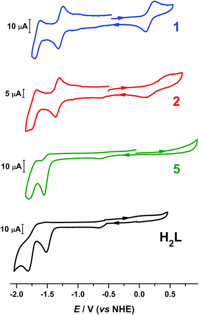 | ||
Fig. 4 Comparison of the voltammograms of 1, 2, [Zn2(μ-L)2] (5) and H2L in 95![[thin space (1/6-em)]](https://www.rsc.org/images/entities/char_2009.gif) : :![[thin space (1/6-em)]](https://www.rsc.org/images/entities/char_2009.gif) 5 (v/v) DMF/H2O solution containing 0.1 M [N(n-Bu)4]ClO4 as supporting electrolyte at scan rate of 100 mV s−1. 5 (v/v) DMF/H2O solution containing 0.1 M [N(n-Bu)4]ClO4 as supporting electrolyte at scan rate of 100 mV s−1. | ||
The cyclic voltammograms of 3 and 4 are nearly identical to their charge-neutral parent species (Fig. S18†). The ligand-centered reduction events are located at indentical potential to 1 and 2. The salient difference is the profile of the quasi-reversible one-electron oxidation that converts 1 and 2 into 3 and 4, respectively. For each, the ΔEp varies: 140 mV in 1, 387 mV in 2, 313 in 3, and 409 mV in 4, and the reduction potential is similarly fluctuating. The non-Nernstian profile of this process arise from the significant change in geometry about one of the Co ions, transitioning from six- to four-coordinate, and the ΔEp is largest for 2 and 4 which possess the more sterically encumbered (LBu)2− ligand.
Electrocatalytic studies of the dinuclear complexes
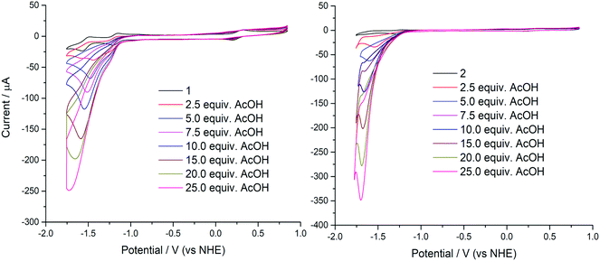
Compounds 1 and 2 were initially evaluated by CV as possible electrocatalysts for proton reduction. Acetic acid was selected because it has a large cathodic reduction potential (EDMF = −2.00 V) ensuring the CVs are unperturbed by any background processes at the electrode.8 An increase of the cathodic current upon addition of various amounts of AcOH was observed for both 1 and 2, as compared to the bare glassy carbon electrode under the same conditions. This is indicative of significant catalytic turnover on the timescale of the electrocatalytic experiment. The catalytic current response to addition of aliquots of AcOH is shown in Fig. 5.In order to verify that AcOH, the proton source used in the catalytic hydrogen evolution studies, was not able to induce dimer cleavage, the stability of 1 upon addition of AcOH was tracked using electronic spectroscopy. In the presence of AcOH (pKa = 13.5),39 the spectrum is unchanged, up to an excess of the acid (Fig. 6). This is in contrast to the effect of the more potent p-toluenesulfonic acid (TsOH), which cleaves the dimer after 4 equiv. of the acid are added (pKa = 2.3).39 This process is reversible as the dicobalt species is reconstituted upon addition of base (Fig. S16†). The same effect was reported for [Cu2(μ-L)2] although this only necessitated 2 equiv. of TsOH to give a monocopper species that catalyzed proton reduction.20 The dicobalt unit in 1 is more robust than its copper counterpart, indicating the structure is likely retained throughout the catalytic process. In it notable that 4 equiv. of TsOH are needed to convert all dicobalt 1 to a monocobalt species which is prompted by protonation of the ligand quinoline groups such that the quinolinium is present in the monocobalt complex.
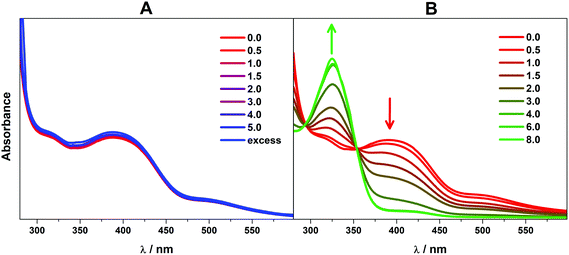 | ||
| Fig. 6 Overlay of electronic spectra of 1 in DMF solution after sequential addition of (A) AcOH (pKa = 13.5) and (B) TsOH (pKa = 2.3). | ||
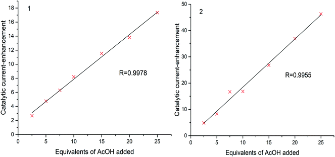
As AcOH is added into the solution an irreversible peak grows with the peak maximum moving to more negative potentials as more AcOH is added. This peak is attributed to proton reduction and is therefore indicative of effective hydrogen evolution catalysis from 1 and 2 (Fig. 5). From these plots, it is evident that the greatest catalytic activity is observed for 2 containing the tert-butyl analogue of the ligand H2L. The catalytic current enhancement parameter ic/ip is defined as the ratio of the peak catalytic current to the reductive current observed in the absence of any protons (the current due to the reduction of 1 to [1]−). This parameter can therefore be used as a measure of the number of times each metal center is reduced, and therefore it is a good estimate for the rate of catalysis.
A plot of catalytic current-enhancement against the equivalents of AcOH added should be linear for catalysis limited by the rate of diffusion of protons such that the reaction appears to be linear with respect to proton concentration (Fig. 7). This is the case for both 1 and 2, indicating that under the conditions studied the concentration of protons is the rate limiting factor.
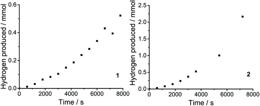
Catalytic activity can also be quantified in terms of the turnover frequency (TOF). TOFs represent the number of reactant molecules converted into the desired product per unit time per moles of catalyst. Direct comparisons of the catalytic activity can be made provided that the estimations of TOF are carried out in a similar manner. TOF was calculated based on the amount of H2 evolved over the duration of the measurement (1 h).11,31 The values of TOFmax for 1 and 2 found to be 10 and 34.6 h−1 molcat−1, respectively. The produced H2 was determned by gas chromatographic analysis (Fig. 9).
Determination of catalytic potentials
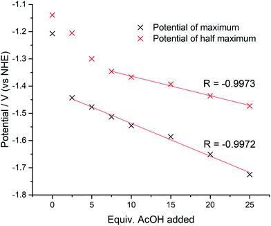
The catalytic potentials of 1, after the addition of 25 equiv. of AcOH, at maximum, half maximum, and catalytic onset are: −1.72 (−1.70), −1.47 (−1.60), and −1.09 (−1.23) V vs. NHE, respectively (values in parenthesis for 2). The value of the current at 0 V was used as the baseline current for the purposes of determination of the potential at half maximum. This point was chosen based on inspection of the cyclic voltammograms indicating that at 0 V the current was consistently at its baseline value.The magnitude of the potential shift from the onset potential was monitored for 1 by calculating the maximum potential and half maximum potential for all amounts of AcOH added. The values are shown in Fig. 8. It is clear that the total potential shift is much smaller for the half maximum potential (0.52 V vs. 0.33 V) as expected, with the gap between the maximum and half maximum potentials expanding. Since the potential shift of the half maximum should be a fraction of the potential shift of the maximum extrapolating the linear portions of the trends should give a point at which the potential shifts equal each other, and thus, it should be equal to 0 V. In the case of 1 this occurs at −1.11 V (vs. NHE), which is in good agreement with the catalytic onset value of −1.09 V. An overpotential of 630 mV is required for 1, based on onset where the catalytic cathodic current increases gradually as a function of the proton concentration (Fig. 7). This value is similar to the ostensible overpotentials of 440 and 560 mV for [CuII(HL)]+ and [NiII(HL)], respectively, both monometallic complexes with one quinoline-protonated ligand that operate with 92% faradaic efficiency.20,21 The overpotential is comparable to related Co-based electrocatalysts, such as [CoII2(bpy)2(L1)]+ (η = 660 mV; L1 is a pentadenate diarylamide-bridged Schiff base),13 [CoII(R3tpy)2]2+ (η = 690 mV; R3tpy are chelating tris-para-substituted-terpyridine ligands),16 [CoIIICl(L1C![[double bond, length as m-dash]](https://www.rsc.org/images/entities/char_e001.gif) O)] and [CoIICl(L2)] (η = 690 and 700 mV, respectively; L1C
O)] and [CoIICl(L2)] (η = 690 and 700 mV, respectively; L1C![[double bond, length as m-dash]](https://www.rsc.org/images/entities/char_e001.gif) O and L2 are pentadenate [N2Npy3] polypyridyl ligands),40 [CoII2(LN6O2)]+ (η = 600 mV; LN6O2 is a bis(phenolate) tetrakis-Schiff base macrocyle),41 and well below the performance of archetypal cobaloximes at 90 mV.9
O and L2 are pentadenate [N2Npy3] polypyridyl ligands),40 [CoII2(LN6O2)]+ (η = 600 mV; LN6O2 is a bis(phenolate) tetrakis-Schiff base macrocyle),41 and well below the performance of archetypal cobaloximes at 90 mV.9
Theoretical calculations
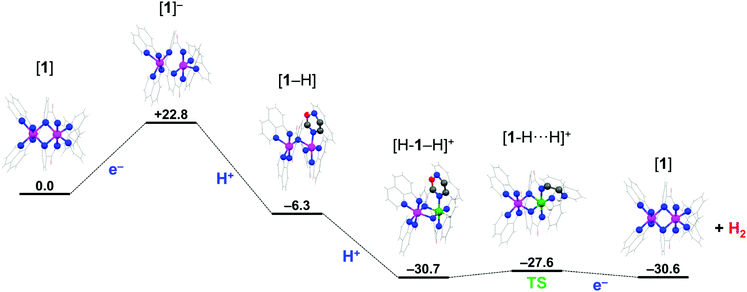
Density functional theoretical (DFT) calculations were undertaken to explore a possible mechanism by which 1 catalyzes the production of H2. Full details of the computational analysis of the molecular and electronic structures starting from 1 through the proposed mechanism are presented in the ESI.† The structure of 1 was optimized using the BP86 pure functional giving a similar helical topology. In the absence of lattice forces the flexibility of the system sees a slight shortening of the average Co–Npy bond to 2.37 Å, with the pyridine groups bridging both cobalt ions. The intermetal distance is 2.770 Å is noticeably shorter than in the solid-state structure at 3.183(3) Å (Table 1 and S25†). The ground state electronic structure was calculated using the broken-symmetry BS(3,3) formalism at the B3LYP level of theory, which accounts for two high-spin Co(II) ions in 1. The S = 0 spin ground state results from an antiferromagnetically coupling between the Co(II) S = 3/2 ions (Fig. S19†). The exchange coupling constant is estimated by the Yamaguchi method is small, at J = −5.5 cm−1,42 and consistent with the experimentally determined magnetic moment that equates to two unpaired spins on each Co(II) ion at room temperature. This solution is 11 kcal mol−1 more stable than the corresponding BS(1,1) calculation for two low-spin S = 1/2 d7 ions, attesting to the weak field strength of the L2− ligand.43 This in part due to its structure and high flexibility compared with more rigid, stronger field bis(imino)pyridine and terpyridine ligands.37,38m,44A plausible mechanism for the electrocatalytic production of H2 is explored using DFT calculations starting from 1. The proposed mechanism is formulated based on two criteria: (i) the quinoline group of the pentadentate N-donor ligand L2− can be protonated and participate in a proton relay,16,20,21,45 and (ii) the dicobalt unit remains intact throughout the cycle, with one site hosting the acid/base chemistry (the proximal Co ion), as established in many HER catalysts,5–8 and the other engaging in redox processes and spin transitions that modulate the activity at the first site (the distal Co ion). Both criteria are operative in native hydrogenases with a bimetallic active site,46 which have inspired similar design features found in some of the best catalytic systems.4,19,47
Catalytic H2 production begins with reduction of 1 to a monoanionic species at the cathode. The optimized structure of [1]− ruptures the Co2N2 core as the Co⋯Co distance increases to 2.944 Å (Table S29†). Each cobalt center is square pyramidal, with an equatorial ligation from one pyridine, one quinoline and two amide nitrogen atoms at distances ranging 1.904–1.995 Å. The apical site is occupied by the second quinoline group at 2.117 Å. The square base of the two pyramids are rotated ∼15° with respect to each other. The electronic structure was obtained from a BS(2,1) calculation to probe the mixed-valent species with a Co(II) ion adjacent a Co(I) ion. The Mulliken spin population analysis reveals the ligands, specifically the bridging pyridine rings, as the locus of the reduction with each cobalt center holding +0.88 spins (Fig. S22†). The spin state at each Co(II) ion has switched from high-spin in 1 to low-spin in [1]− which is driven by the increased field strength for the reduced ligands. The additional electron is equally divided over both ligands with −0.38 on each (i.e. L2− → L2.5−). As a result, there is only a slight lengthening of the bonds about the amide moiety as the structural changes brought about by the reduction of the ligand to its π-radical form are averaged over both ligands.38m,44 Hence, the electronic structure is best represented by the limiting resonance forms [Co2II(μ-L3−˙)(μ-L2−)]− ↔ [Co2II(μ-L2−)(μ-L3−˙)]−, consistent with Class III mixed valency.48
The key feature observed with [1]− is switch to low-spin causes a lengthening of one of the Co–Nqn bonds facilitating its cleavage at low pH through protonation of the quinoline nitrogen. This is the process by which the mononuclear complexes Ni(II) and Cu(II) with the L2− ligand produce a vacant coordination site to become catalytically active,20,21 and is a frequently encountered phenomenon for pyridyl-based ligands.16,45 The optimized structure of the protonated monoanion, [1-H], sees the protonated quinoline nitrogen atom rotated away from the proximal Co(II) center and stabilized by an intraligand hydrogen bond to the amide carbonyl group. This orientation is 6.6 kcal mol−1 more favorable than having the protonated quinoline nitrogen atom perched above the Co(II) ion. The addition of the proton breaks the equivalence of the metal ions and ligands, with the pyridine group of the unprotonated ligand returning to a bridging mode ensuring both Co(II) centers remain five-coordinate. Broken-symmetry calculations highlight the inequivalence of the ligands, with the unpaired spin now exclusively residing on the protonated ligand including a quotient deposited to the pendant quinolinium (Fig. S23†). The cobalt ions retain their +II oxidation state with each carrying +0.9 spins, and compound formulated as [Co2II(μ-L2−)(μ-HL2−˙)]. Interestingly, there is no energetic preference for either a low- or high-spin configuration for the distal Co(II) ion (Table S32†).
The first two steps of the mechanism presented in Scheme 3 describe a proton-coupled electron transfer (PCET) that is initiated by electron transfer (ET) to 1 which is subsequently protonated by AcOH. The PCET is a stepwise process on account that AcOH cannot directly protonate 1. The intraligand hydrogen-bond in [1-H] stabilizes this species 6.3 kcal mol−1 compared to 1 (Scheme 3). The subsequent steps toward H2 generation involve addition of the second proton to the vacant site of the proximal Co(II) ion leading to the formation of a Co(III)-hydride species; where the second electron is provided by the reduced ligand.15 The mechanism presented here is analogous to those proposed for H2 production in other molecular cobalt species.5,7,49,50 The optimized geometry of [H-1 − H]+ has the pyridine group of both ligands in a bridging mode and each cobalt center six-coordinate. The CoIII–H distance of 1.437 Å is in the range expected for CoIII monohydride species,50,51 with the distal Co(II) ion in a high-spin configuration, though this is only 2.3 kcal mol−1 more stable than the low-spin configuration (Table S35†). The Mulliken spin distribution supports this oxidation state assignment with +2.64 spins on the Co(II) center and none on the Co(III) ion (Fig. S24†). The electronic structure is formulated [CoII(μ-L2−)CoIII(H)(μ-HL−)]+ to distinguish that the Co(III) center has the hydride and the quinolinium group in its vicinity. The final step of the mechanism is the heterolytic formation of the H–H bond as proposed for the Ni(II) and Cu(II) systems.20,21 This requires reorientation of the pendant protonated quinoline ring such that its proton is positioned above the Co(III) hydride and represents a very small 3 kcal mol−1 energy barrier to give the [1-H⋯H]+ intermediate (Scheme 3). With the system under an applied potential, 1 is regenerated by the addition of a second electron after expulsion of the H2 molecule. Alternatively, reduction of the Co(III)-hydride species [H-1 − H]+ could precede formation of the H⋯H intermediate as the exact sequence of these events can only be speculated at present. Reduction of the ligand is a means to modulate the pKa of the metal-hydride and facilitate its protonation to produce H2.5,7,15,49,50 Here, the proximal Co ion remains +III, and the ligand accommodates the additional electron, which is able to provide a reducing equivalent to the Co(III) ion after the release of H2.
Conclusions
The molecular and electronic structures of two neutral dicobalt(II) complexes 1 and 2, and their one-electron oxidation to mixed-valent CoIIICoII monocationic 3 and 4 are described. The cationic compounds 3 and 4 constitute rare examples of mixed-valent species with topologically adjacent octahedral (N6) and tetrahedral (N4) coordination environments for the Co(III) and Co(II) ions.52 Both neutral complexes were then investigated for electrocatalytic proton reduction activity in DMF with AcOH as a proton source. Compound 2, in which the electron donating tert-butyl group has been incorporated into the 4-position of the pyridine moiety, exhibited higher activity than its unsubstituted analogue 1 and thus, the electron donating substituent has a positive impact on the turnover frequency. The electron donation tert-butyl group conversely raised the catalytic onset potential of 2. The amount of H2 produced was limited only by the availability of protons while the molecular catalysts appear to retain their integrity during the course of the catalytic study. Based on DFT results and experimental data (electrochemistry) the first step of the mechanism involves a ligand-based reduction to generate [1]− and the concomitant switch to low-spin in both Co(II) ions. This reduced complex is protonated by AcOH and to first create the vacant coordination site at the proximal Co(II) center which is followed by formation of the catalytically ubiquitous Co(III) hydride. The spin state switching of the distal Co(II) ion serves to modulate the reactivity of the proximal Co center as well as promote redox interplay with the ligands.This work marks the importance of development of modular molecular species for the catalytic evolution of hydrogen which can be used further as sustainable source of energy. Additionally, the study opens the door for further exploration allowing the design of new modular molecular catalysts and understanding of system specific mechanistic aspects which are crucial for the development of highly efficient catalysts for large scale applications.
Conflicts of interest
There are no conflicts to declare.Acknowledgements
The research work was supported by the Hellenic Foundation for Research and Innovation (HFRI) under the HFRI PhD Fellowship grant (Fellowship Number: 1213). The authors would like to thank the Unit ORBITRAP-LC-MS of the University of Ioannina. H. N. M would like to thank the School of Chemistry at the University of Glasgow for the support.References
- N. S. Lewis and D. G. Nocera, Proc. Natl. Acad. Sci. U. S. A., 2006, 103, 15729 CrossRef.
- D. V. Esposito, S. T. Hunt, A. L. Stottlemyer, K. D. Dobson, B. E. McCandless, R. W. Birkmire and J. G. Chen, Angew. Chem., Int. Ed., 2010, 49, 9859 CrossRef.
- I. E. L. Stephens and I. Chorkendorff, Angew. Chem., Int. Ed., 2011, 50, 1476 CrossRef.
- (a) S. J. Connelly Robinson and D. M. Heinekey, Chem. Commun., 2017, 53, 669 RSC; (b) J. McAllister, N. A. G. Bandeira, J. C. McGlynn, A. Y. Ganin, Y.-F. Song, C. Bo and H. N. Miras, Nat. Commun., 2019, 10, 370 CrossRef.
- V. Artero, M. Chavarot-Kerlidou and M. Fontecave, Angew. Chem., Int. Ed., 2011, 50, 7238 CrossRef.
- W. T. Eckenhoff, Coord. Chem. Rev., 2018, 373, 295 CrossRef.
- W. T. Eckenhoff, W. R. McNamara, P. Du and R. Eisenberg, Biochim. Biophys. Acta, 2013, 1827, 958 CrossRef.
- J. L. Dempsey, B. S. Brunschwig, J. R. Winkler and H. B. Gray, Acc. Chem. Res., 2009, 42, 1995 CrossRef.
- X. Hu, B. S. Brunschwig and J. C. Peters, J. Am. Chem. Soc., 2007, 129, 8988 CrossRef.
- (a) X. L. Hu, B. M. Cossairt, B. S. Brunschwig, N. S. Lewis and J. C. Peters, Chem. Commun., 2005, 4723 RSC; (b) G. N. Schrauzer, Acc. Chem. Res., 1968, 1, 97 CrossRef.
- V. Artero and J.-M. Saveant, Energy Environ. Sci., 2014, 7, 3808 RSC.
- (a) S. Kal, A. S. Filatov and P. H. Dinolfo, Inorg. Chem., 2013, 52, 13963 CrossRef; (b) S. A. Ranaweera, M. D. Rowe, K. B. Walters, W. P. Henry, M. G. White and J. M. Rodriguez, Appl. Catal., A, 2017, 529, 108 CrossRef; (c) N. K. Szymczak, L. A. Berben and J. C. Peters, Chem. Commun., 2009, 6729 RSC; (d) E. L. Uzunova, Catal. Sci. Technol., 2019, 9, 1039 RSC.
- K. K. Kpogo, S. Mazumder, D. Wang, H. B. Schlegel, A. T. Fiedler and C. N. Verani, Chem. – Eur. J., 2017, 23, 9272 CrossRef.
- S. Mandal, S. Shikano, Y. Yamada, Y.-M. Lee, W. Nam, A. Llobet and S. Fukuzumi, J. Am. Chem. Soc., 2013, 135, 15294 CrossRef.
- (a) G. C. Tok, A. T. S. Freiberg, H. A. Gasteiger and C. R. Hess, ChemCatChem, 2019, 11, 3973 CrossRef; (b) A. Z. Haddad, S. P. Cronin, M. S. Mashuta, R. M. Buchanan and C. A. Grapperhaus, Inorg. Chem., 2017, 56, 11254 CrossRef; (c) R. Jain, A. Al Mamun, R. M. Buchanan, P. M. Kozlowski and C. A. Grapperhaus, Inorg. Chem., 2018, 57, 13486 CrossRef; (d) G.-G. Luo, H.-L. Zhang, Y.-W. Tao, Q.-Y. Wu, D. Tian and Q. Zhang, Inorg. Chem. Front., 2019, 6, 343 RSC; (e) B. H. Solis, A. G. Maher, D. K. Dogutan, D. G. Nocera and S. Hammes-Schiffer, Proc. Natl. Acad. Sci. U. S. A., 2016, 113, 485 CrossRef; (f) T. Straistari, J. Fize, S. Shova, M. Réglier, V. Artero and M. Orio, ChemCatChem, 2016, 9, 2262 CrossRef.
- S. Aroua, T. K. Todorova, V. Mougel, P. Hommes, H.-U. Reissig and M. Fontecave, ChemCatChem, 2017, 9, 2099 CrossRef CAS.
- (a) A. Z. Haddad, B. D. Garabato, P. M. Kozlowski, R. M. Buchanan and C. A. Grapperhaus, J. Am. Chem. Soc., 2016, 138, 7844 CrossRef CAS; (b) J. W. Jurss, R. S. Khnayzer, J. A. Panetier, K. A. El Roz, E. M. Nichols, M. Head-Gordon, J. R. Long, F. N. Castellano and C. J. Chang, Chem. Sci., 2015, 6, 4954 RSC; (c) T. J. Sherbow, J. C. Fettinger and L. A. Berben, Inorg. Chem., 2017, 56, 8651 CrossRef CAS.
- (a) B. E. Barton, M. T. Olsen and T. B. Rauchfuss, J. Am. Chem. Soc., 2008, 130, 16834 CrossRef CAS; (b) M. M. Roubelakis, D. K. Bediako, D. K. Dogutan and D. G. Nocera, Energy Environ. Sci., 2012, 5, 7737 RSC.
- M. Rakowski DuBois and D. L. DuBois, Chem. Soc. Rev., 2009, 38, 62 RSC.
- K. Majee, J. Patel, B. Das and S. K. Padhi, Dalton Trans., 2017, 46, 14869 RSC.
- K. Majee, J. Patel, S. Rai, B. Das, B. Panda and S. K. Padhi, Phys. Chem. Chem. Phys., 2016, 18, 21640 RSC.
- (a) O. R. Luca, S. J. Konezny, J. D. Blakemore, D. M. Colosi, S. Saha, G. W. Brudvig, V. S. Batista and R. H. Crabtree, New J. Chem., 2012, 36, 1149 RSC; (b) V. Lyaskovskyy and B. de Bruin, ACS Catal., 2012, 2, 270 CrossRef CAS; (c) K. E. Rosenkoetter, M. K. Wojnar, B. J. Charette, J. W. Ziller and A. F. Heyduk, Inorg. Chem., 2018, 57, 9728 CrossRef CAS.
- (a) R. S. Khnayzer, V. S. Thoi, M. Nippe, A. E. King, J. W. Jurss, K. A. El Roz, J. R. Long, C. J. Chang and F. N. Castellano, Energy Environ. Sci., 2014, 7, 1477 RSC; (b) M. Nippe, R. S. Khnayzer, J. A. Panetier, D. Z. Zee, B. S. Olaiya, M. Head-Gordon, C. J. Chang, F. N. Castellano and J. R. Long, Chem. Sci., 2013, 4, 3934 RSC; (c) Y. Sun, J. P. Bigi, N. A. Piro, M. L. Tang, J. R. Long and C. J. Chang, J. Am. Chem. Soc., 2011, 133, 9212 CrossRef CAS.
- H.-H. Xu, X. Tao, Y.-Q. Li, Y.-Z. Shen and Y.-H. Wei, Acta Crystallogr., Sect. C: Cryst. Struct. Commun., 2011, 67, m93 Search PubMed.
- G. A. Bain and J. F. Berry, J. Chem. Educ., 2008, 85, 532 CrossRef CAS.
- G. M. Sheldrick, Acta Crystallogr., Sect. A: Found. Crystallogr., 1990, 46, 467 CrossRef.
- G. M. Sheldrick, Acta Crystallogr., Sect. A: Found. Crystallogr., 2008, 64, 112 CrossRef CAS.
- L. J. Farrugia, J. Appl. Crystallogr., 1999, 32, 837 CrossRef CAS.
- R. C. Clark and J. S. Reid, Acta Crystallogr., Sect. A: Found. Crystallogr., 1995, 51, 887 CrossRef.
- A. J. Bard and L. R. Faulkner, Electrochemical Methods: Fundamentals and Applications, John Wiley & Sons, New York, 2001 Search PubMed.
- (a) C. Costention and J.-M. Savéant, ChemElectroChem, 2014, 1, 1226 CrossRef; (b) E. S. Rountree, B. D. McCarthy, T. T. Eisenhart and J. L. Dempsey, Inorg. Chem., 2014, 53, 9983 CrossRef CAS.
- T. Heldt, R. Mukkamala, G. B. Moody and R. G. Mark, Open Pacing, Electrophysiol. Ther. J., 2010, 3, 45 Search PubMed.
- J. Zhang, E. Khaskin, N. P. Anderson, P. Y. Zavalij and A. N. Vedernikov, Chem. Commun., 2008, 3625 RSC.
- R. A. Begum, V. W. Day, M. Kumar, J. Gonzalez, T. A. Jackson and K. Bowman-James, Inorg. Chim. Acta, 2014, 417, 287 CrossRef CAS.
- M. H. Reineke, M. D. Sampson, A. L. Rheingold and C. P. Kubiak, Inorg. Chem., 2015, 54, 3211 CrossRef CAS.
- (a) D. F. Back, G. M. de Oliveira, C. M. Canabarro and B. A. Iglesias, Z. Anorg. Allg. Chem., 2015, 641, 941 CrossRef CAS; (b) V. Chandrasekhar, A. Dey, A. J. Mota and E. Colacio, Inorg. Chem., 2013, 52, 4554 CrossRef CAS; (c) B. Chiari, A. Cinti, O. Crispu, F. Demartin, A. Pasini and O. Piovesana, J. Chem. Soc., Dalton Trans., 2001, 3611 RSC; (d) S. K. Dey and A. Mukherjee, New J. Chem., 2014, 38, 4985 RSC; (e) A. Panja and D. M. Eichhorn, J. Coord. Chem., 2009, 62, 2600 CrossRef CAS.
- (a) C. C. Scarborough, S. Sproules, T. Weyhermüller, S. DeBeer and K. Wieghardt, Inorg. Chem., 2011, 50, 12446 CrossRef CAS; (b) J. England, C. C. Scarborough, T. Weyhermüller, S. Sproules and K. Wieghardt, Eur. J. Inorg. Chem., 2012, 4605 CrossRef CAS; (c) C. C. Scarborough, K. M. Lancaster, S. DeBeer, T. Weyhermüller, S. Sproules and K. Wieghardt, Inorg. Chem., 2012, 51, 3718 CrossRef CAS.
- (a) A. C. Bowman, S. Sproules and K. Wieghardt, Inorg. Chem., 2012, 51, 3707 CrossRef CAS; (b) A. C. Bowman, J. England, S. Sproules, T. Weyhermüller and K. Wieghardt, Inorg. Chem., 2013, 52, 2242 CrossRef CAS; (c) S. C. Bart, E. Lobkovsky, E. Bill and P. J. Chirik, J. Am. Chem. Soc., 2006, 128, 5302 CrossRef CAS; (d) A. C. Bowman, A. M. Tondreau, E. Lobkovsky, G. W. Margulieux and P. J. Chirik, Inorg. Chem., 2018, 57, 9634 CrossRef CAS; (e) B. de Bruin, E. Bill, E. Bothe, T. Weyhermüller and K. Wieghardt, Inorg. Chem., 2000, 39, 2936 CrossRef CAS; (f) T. D. Manuel and J.-U. Rohde, J. Am. Chem. Soc., 2009, 131, 15582 CrossRef CAS; (g) C. C. Lu, E. Bill, T. Weyhermüller, E. Bothe and K. Wieghardt, J. Am. Chem. Soc., 2008, 130, 3181 CrossRef CAS; (h) C. C. Lu, E. Bill, T. Weyhermüller, E. Bothe and K. Wieghardt, Inorg. Chem., 2007, 46, 7880 CrossRef CAS; (i) D. Zhu, I. Thapa, I. Korobkov, S. Gambarotta and P. H. M. Budzelaar, Inorg. Chem., 2011, 50, 9879 CrossRef CAS; (j) E. E. Benson, K. A. Grice, J. M. Smieja and C. P. Kubiak, Polyhedron, 2013, 58, 229 CrossRef CAS; (k) J. M. Smieja and C. P. Kubiak, Inorg. Chem., 2010, 49, 9283 CrossRef CAS; (l) G. D. Jones, J. L. Martin, C. McFarland, O. R. Allen, R. E. Hall, A. D. Haley, R. J. Brandon, T. Konovalona, P. J. Desrochers, P. Pulay and D. A. Vicic, J. Am. Chem. Soc., 2006, 128, 13175 CrossRef CAS; (m) A. C. Bowman, C. Milsmann, C. C. Hojilla Atienza, E. Lobkovsky, K. Wieghardt and P. J. Chirik, J. Am. Chem. Soc., 2010, 132, 1676 CrossRef CAS.
- (a) M. L. Pegis, D. J. Martin, C. F. Wise, A. C. Brezny, S. I. Johnson, L. E. Johnson, N. Kumar, S. Raugei and J. M. Mayer, J. Am. Chem. Soc., 2019, 141, 8315–8326 CAS; (b) F. Maran, D. Celadon, M. G. Severin and E. Vianello, J. Am. Chem. Soc., 1991, 113, 9320–9329 CrossRef CAS; (c) G. A. N. Felton, R. S. Glass, D. L. Lichtenberger and D. H. Evans, Inorg. Chem., 2006, 45, 9181–9184 CrossRef CAS.
- D. Basu, S. Mazumder, X. Shi, H. Baydoun, J. Niklas, O. Poluektov, H. B. Schlegel and C. N. Verani, Angew. Chem., Int. Ed., 2015, 54, 2105 CrossRef CAS.
- S. Kal, A. S. Filatov and P. H. Dinolfo, Inorg. Chem., 2014, 53, 7137 CrossRef CAS.
- (a) K. Yamaguchi, Y. Takahara and T. Fueno, in Applied Quantum Chemistry, ed. V. H. Smith, Reidel, Dordrecht, The Netherlands, 1986, p. 155 Search PubMed; (b) T. Soda, Y. Kitagawa, T. Onishi, Y. Takano, Y. Shigetu, H. Nagao, Y. Yoshioka and K. Yamaguchi, Chem. Phys. Lett., 2000, 319, 223 CrossRef CAS.
- M. Ray, D. Ghosh, Z. Shirin and R. Mukherjee, Inorg. Chem., 1997, 36, 3568 CrossRef CAS.
- (a) V. A. Schmidt, J. M. Hoyt, G. W. Margulieux and P. J. Chirik, J. Am. Chem. Soc., 2015, 137, 7903 CrossRef CAS; (b) P. J. Chirik, Acc. Chem. Res., 2015, 48, 1687 CrossRef CAS.
- (a) J. Wang, C. Li, Q. Zhou, W. Wang, Y. Hou, B. Zhang and X. Wang, Catal. Sci. Technol., 2016, 6, 8482 RSC; (b) P. Zhang, M. Wang, Y. Yang, T. Yao and L. Sun, Angew. Chem., Int. Ed., 2014, 53, 13803 CrossRef CAS; (c) Z. Han, L. Shen, W. W. Brennessel, P. L. Holland and R. Eisenberg, J. Am. Chem. Soc., 2013, 135, 14659 CrossRef CAS; (d) W. R. McNamara, Z. Han, C.-J. Yin, W. W. Brennessel, P. L. Holland and R. Eisenberg, Proc. Natl. Acad. Sci. U. S. A., 2012, 109, 15594 CrossRef CAS; (e) R.-Z. Liao, M. Wang, L. Sun and P. E. M. Siegbahn, Dalton Trans., 2015, 44, 9736 RSC.
- (a) J. A. Birrell, O. Rüdiger, E. Reijerse and W. Lubitz, Joule, 2017, 1, 61 CrossRef CAS; (b) W. Lubitz, H. Ogata, O. Rüdiger and E. Reijerse, Chem. Rev., 2014, 114, 4081 CrossRef CAS.
- A. Barrozo and M. Orio, ChemSusChem, 2019, 12, 4905 CrossRef CAS.
- M. B. Robin and P. Day, Adv. Inorg. Chem. Radiochem., 1967, 10, 247 CrossRef CAS.
- (a) B. H. Solis and S. Hammes-Schiffer, J. Am. Chem. Soc., 2011, 133, 19036 CrossRef CAS; (b) B. H. Solis and S. Hammes-Schiffer, Inorg. Chem., 2011, 50, 11252 CrossRef CAS.
- A. Bhattacharjee, M. Chavarot-Kerlidou, E. S. Andreiadis, M. Fontecave, M. J. Field and V. Artero, Inorg. Chem., 2012, 51, 7087 CrossRef CAS.
- E. S. Wiedner, J. A. S. Roberts, W. G. Dougherty, W. S. Kassel, D. L. DuBois and R. M. Bullock, Inorg. Chem, 2013, 52, 9975 Search PubMed.
- S. K. Padhi, S. Rai and Sk S. Akhter, Inorg. Chem., 2020, 59(11), 7810–7821 CrossRef CAS.
Footnotes |
| † Electronic supplementary information (ESI) available: General experimental procedures, spectroscopic, crystallographic and computational data for 1–4. CCDC 1989902–1989905. For ESI and crystallographic data in CIF or other electronic format see DOI: 10.1039/d0dt02617d |
| ‡ These authors contributed equally in this work. |
| This journal is © The Royal Society of Chemistry 2020 |

