 Open Access Article
A generalizable method for the construction of MOF@polymer functional composites through surface-initiated atom transfer radical polymerization†
Sanfeng
He
,
Hongliang
Wang
,
Cuizheng
Zhang
,
Songwei
Zhang
,
Yi
Yu
,
Yongjin
Lee
and
Tao
Li
 *
*
School of Physical Science and Technology, ShanghaiTech University, Shanghai 201210, China. E-mail: litao1@shanghaitech.edu.cn
First published on 12th December 2018
Abstract
We report a generalizable approach to construct MOF@polymer functional composites through surface-initiated atom transfer radical polymerization (SI-ATRP). Unlike conventional SI-ATRP that requires covalent pre-anchoring of the initiating group on substrate surfaces, in our approach, a rationally designed random copolymer (RCP) macroinitiator first self-assembles on MOF surfaces through inter-chain hydrogen bond crosslinking. Subsequent polymerization in the presence of a crosslinking monomer covalently threads these polymer chains into a robust network, physically confining the MOF particle inside the polymer shell. We demonstrated the universality of this approach by growing various polymers on five MOFs of different metals (Zr, Zn, Co, Al, and Cr) with complete control over shell thickness, functionality and layer sequence while still retaining the inherent porosity of the MOFs. Moreover, the wettability of UiO-66 can be continuously tuned from superhydrophilic to superhydrophobic simply through judicious monomer(s) selection. We also demonstrated that a 7 nm polystyrene shell can effectively shield UiO-66 particles against 1 M H2SO4 and 1 M NaOH at elevated temperature, enabling their potential application in demanding chemical environments.
Introduction
Grafting polymers onto nanoparticle (NP) surfaces is a common practice to manipulate nanoparticles' surface energy as well as their interactions with neighboring media. Benefiting from the rich chemistry and physical behaviors of polymers, a number of properties of nanomaterials such as dispersibility,1 chemical stability,2 charge transport behavior,3 self-assembly behavior,4 molecular recognition,5 mechanical properties6etc. can be precisely controlled by tuning the composition, morphology, and chain conformation of the polymer shell. This has led to extensive research efforts to construct NPs@polymer architectures for various applications.Metal–organic framework nanoparticles (MOF NPs) represent a new class of structurally rigid, highly diverse nano-building blocks showing promises in many potential areas.7–14 While their bulk counterparts, in most cases, rely exclusively on their exquisite pore chemistry, MOF NPs, like other nanomaterials, often benefit from “soft” polymeric coatings with the resultant MOF@polymer composites exhibiting unique performance in bio-imaging,15,16 therapeutics,17–22 membrane gas separation,23,24 catalysis25,26etc. In addition, combining the rich library of polymers and MOFs in such a hierarchy may lead to the emergence of new collective properties inaccessible by either of them alone.27,28 Although highly desirable, there is a lack of a generalizable method for the construction of well-defined MOF@polymer architectures with tunable composition, thickness and conformation of the polymer layer.
Surface-initiated atom transfer radical polymerization29 (SI-ATRP) is a well-developed technique for growing “soft” polymer coatings on various nanomaterials with excellent control over a series of coating parameters. However, applying this method to MOFs has new challenges. The extreme diversity of MOF materials makes it difficult to find a common covalent anchoring point for the installation of the ATRP initiator which is an essential step in a traditional SI-ATRP process. Moreover, the limited stability and large pore openings of some MOFs also pose additional hassles for surface specific modification. In fact, current examples of SI-ATRP on MOFs exclusively rely on the presence of an amino functionality as a covalent anchoring point for the installation of α-bromoisobutyryl bromide (BiBB) which is not applicable to other MOFs.24,30–36 This significantly hampers the further development of MOF@polymer composites.
Here, we present a generalizable method to perform SI-ATRP on MOFs. A random copolymer (RCP) containing multiple carboxylic acid groups and bromoisobutyrate (BiB) functional groups along the polymer chain (Fig. 1A) is first self-assembled onto MOF surfaces through inter-chain hydrogen bond crosslinking accompanied by weak MOF/polymer interactions. The temporarily immobilized RCP allows SI-ATRP to be initiated through the BiB groups along the side chains with a monomer and a crosslinker.37–39 Utilizing the reversible-deactivation feature of ATRP,40 a second layer of polymer (linear or crosslinked) can be subsequently grown from the first layer through another SI-ATRP step thus endowing MOF surfaces with new functionalities (Fig. 1B). Such a strategy features several advantages. First, the hydrogen bond driven self-assembly process of the RCP on MOFs is independent of the MOF composition thereby generalizable to different MOFs. Second, the macromolecular nature of the RCP prevents it from diffusing into the MOF pores, therefore ensuring surface specific modification. Third, the covalently crosslinked polymer provides a robust coating which can withstand aggressive chemical treatment. Last, the reversible-deactivation feature of SI-ATRP presents a powerful tool for total control over many parameters of the polymer shell including thickness, functionality, and sequence.29 Using five classic MOFs of different metals, we demonstrate the generalizability of this approach for the construction of a library of MOF@polymer functional composites with controlled shell thickness, functionality and sequence. Unique properties such as wettability, gas sorption properties, and chemical stability derived from such a core–shell architecture were also studied in detail.
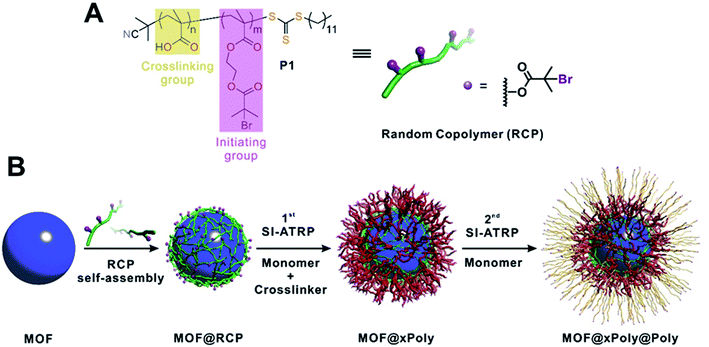 | ||
| Fig. 1 (A) Molecular structure of the RCP macroinitiator, P1. (B) Schematic illustration of typical experimental procedures for growing polymer shells on a MOF particle. | ||
Results and discussion
Synthesis and characterization of RCP and MOFs
The RCP was synthesized through reversible addition–fragmentation chain transfer (RAFT) polymerization using 2-cyano-2-propyl dodecyl trithiocarbonate as the RAFT agent41 and tert-butyl methacrylate (tBuMA) and 2-(2-bromoisobutyryloxy) ethyl methacrylate (BIEM) as monomers (Fig. 1A). The number average molecular weight (Mn) and dispersity (Đ) of the product, poly(BIEM-co-tBuMA), were 10.3 kDa and 1.48, respectively, according to gel permeation chromatography (GPC) experiments. The BIEM/tBuMA ratio was 8.5![[thin space (1/6-em)]](https://www.rsc.org/images/entities/char_2009.gif) :
:![[thin space (1/6-em)]](https://www.rsc.org/images/entities/char_2009.gif) 1 as confirmed by the 1H-NMR spectrum (Fig. S1†). After hydrolysis, poly(BIEM-co-MAA) (MAA is methacrylic acid) was obtained and denoted as P1 (Fig. S2†). On average, each P1 chain comprises 4 carboxylic acid groups on the backbone and 35 BiB groups (detailed calculation can be found in the ESI, Section 3†). The presence of carboxylic acid groups allows inter-chain crosslinking through hydrogen bonds on the MOF surface whereas the BiB enables ATRP. The ratio between the two monomers and the molecular weight of the polymer can be varied. However, the polymer must be soluble in the given organic solvent environment to assist the dispersion of the MOF particles. In addition, a second RCP, poly(BIEM-co-MAA) (denoted as P2, PDI = 6.89; BIEM
1 as confirmed by the 1H-NMR spectrum (Fig. S1†). After hydrolysis, poly(BIEM-co-MAA) (MAA is methacrylic acid) was obtained and denoted as P1 (Fig. S2†). On average, each P1 chain comprises 4 carboxylic acid groups on the backbone and 35 BiB groups (detailed calculation can be found in the ESI, Section 3†). The presence of carboxylic acid groups allows inter-chain crosslinking through hydrogen bonds on the MOF surface whereas the BiB enables ATRP. The ratio between the two monomers and the molecular weight of the polymer can be varied. However, the polymer must be soluble in the given organic solvent environment to assist the dispersion of the MOF particles. In addition, a second RCP, poly(BIEM-co-MAA) (denoted as P2, PDI = 6.89; BIEM![[thin space (1/6-em)]](https://www.rsc.org/images/entities/char_2009.gif) :
:![[thin space (1/6-em)]](https://www.rsc.org/images/entities/char_2009.gif) tBuMA = 7.4
tBuMA = 7.4![[thin space (1/6-em)]](https://www.rsc.org/images/entities/char_2009.gif) :
:![[thin space (1/6-em)]](https://www.rsc.org/images/entities/char_2009.gif) 1), was synthesized through AIBN initiated non-controlled free radical polymerization (Fig. S3 and S4†) to demonstrate the robustness of our approach.
1), was synthesized through AIBN initiated non-controlled free radical polymerization (Fig. S3 and S4†) to demonstrate the robustness of our approach.
Next, five MOFs, UiO-66, ZIF-8, ZIF-67, MIL-96(Al) and MIL-101(Cr), were selected for this study as they represent five widely used metals for MOF synthesis: Zr, Zn, Co, Al and Cr. These MOFs were synthesized according to previously reported methods with slight modification.42–46 Scanning electron microscopy (SEM) and transmission electron microscopy (TEM) images (Fig. S5 and S6†) show that single crystalline particles with well-defined crystallographic facets and narrow dispersity were obtained with average sizes of 654 ± 16 nm, 63 ± 3 nm, 243 ± 13 nm, 996 ± 34 nm, and 363 ± 22 nm, respectively. Their crystallinity and phase purity were confirmed by powder X-ray diffraction (PXRD) patterns (Fig. S7–11†).
Construction of MOF@polymer functional composites
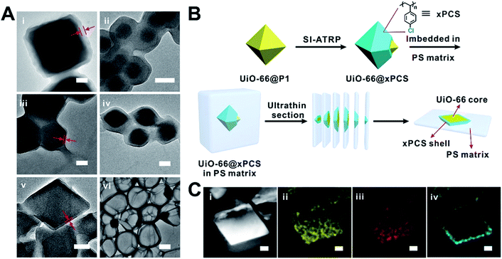
Taking UiO-66 as an example, in a typical experiment, P1 was loaded onto UiO-66 particles’ surfaces through a 1 min incubation period in dichloromethane (DCM). Then the excess P1 was removed to give UiO-66@P1. The dispersibility of UiO-66 particles in DCM was significantly improved as shown in Fig. S12.† The X-ray photoelectron spectrum (XPS) of UiO-66@P1 clearly shows a peak at 70.2 eV corresponding to the 3d orbital electrons of Br confirming the presence of P1 on the surface of UiO-66 (Fig. S13†). Thermogravimetric analysis (TGA) revealed that the P1 loading was ∼30 mg g−1 of UiO-66 (Table S5†). Through calculation, the average surface density of the BiB was estimated to be 5.3/nm2 (ESI, Section 3†).Next, SI-ATRP was performed on UiO-66@P1 in a styrene (St) and 1,4-butanediol diacrylate (BDDA) mixture. UiO-66@xPS (xPS is crosslinked polystyrene) was isolated as the product. The TEM image clearly shows a layer of PS with an average thickness of 32 ± 2 nm uniformly grown on the UiO-66 surface (Fig. 2Ai and S14†). After digesting UiO-66 with HF, the polymer shell remains intact (Fig. 2Avi) suggesting that the covalently crosslinked network is both chemically and mechanically stable. Similarly, using P2 as the macroinitiator, xPS coated UiO-66 (denoted as UiO-66@xPS′) was also successfully obtained indicating that the strict molecular weight control of the RCP is not necessary (Fig. S15†).
Extending this strategy to ZIF-8, ZIF-67, MIL-96 and MIL-101(Cr) afforded ZIF-8@xPS, ZIF-67@xPS, MIL-96(Al)@xPS, and MIL-101(Cr)@xPS with a coating thickness of 36 ± 2 nm, 13 ± 1 nm, 78 ± 3 nm, and 12 ± 1 nm, respectively (Fig. 2Aii–v). No loss of crystallinity was observed after modification (Fig. S7–11†). To visualize the spatial distribution of the polymer layer, we coated UiO-66 particles with a chlorine containing polymer (Fig. S16A and B†), poly(4-chlorostyrene) (PCS), using similar protocols as described above. The product, UiO-66@xPCS, was sliced into 100 nm sections using an ultramicrotome for TEM analysis (Fig. 2B and S16C†). Energy dispersive X-ray spectroscopy (EDS) mapping shows that Zr, O, and C were evenly distributed across the particles whereas the Cl signal was exclusively located on the edge of the MOF particle suggesting that the polymerization indeed occurred only on the MOF surface (Fig. 2C).
Molecular dynamics (MD) simulation of the RCP self-assembly on the MOF surface
To understand the assembly mechanism of the RCP on MOF surfaces, we performed molecular dynamics (MD) simulation. A total of 10 RCP chains (per MOF surface) each containing 35 BIEM and 4 MAA were constructed in a simulation cell along with toluene molecules and an exposed [100] surface of UiO-66 terminated by hydroxyl groups and water molecules. After MD simulation, all polymer chains densely packed onto the MOF surface (Fig. S17†). No diffusion of polymer chains into MOF pores was observed (Fig. S18†). By analyzing the distribution of hydrogen bonds, we found that each chain forms an average of ∼2 intra-molecular and ∼2 inter-molecular hydrogen bonds formed between two carboxylic acid groups or carboxylic acid–ester groups (Fig. S19–21†). In contrast, hydrogen bonds were rarely observed between the polymer and MOF. These results confirmed that the adsorption process of the RCP on MOF surfaces did occur through an inter-chain hydrogen bond induced self-assembly and thus is non-specific to different MOFs.Manipulating coating thickness, functionality and sequence
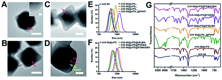
We demonstrated that the PS coating thickness on UiO-66 can be controlled by tuning the polymerization time and monomer concentration (Fig. 3A–C, 2Ai and Table S2†). When the monomer/solvent volumetric ratios were fixed at 1![[thin space (1/6-em)]](https://www.rsc.org/images/entities/char_2009.gif) :
:![[thin space (1/6-em)]](https://www.rsc.org/images/entities/char_2009.gif) 2 and 1
2 and 1![[thin space (1/6-em)]](https://www.rsc.org/images/entities/char_2009.gif) :
:![[thin space (1/6-em)]](https://www.rsc.org/images/entities/char_2009.gif) 1 and the polymerization time was increased from 6 h to 12 h, the polymer thickness increased from 13 to 32 nm and 23 to 59 nm, respectively. Moreover, we fixed the reaction time at 6 and 12 h and increased the monomer/solvent ratio from 1
1 and the polymerization time was increased from 6 h to 12 h, the polymer thickness increased from 13 to 32 nm and 23 to 59 nm, respectively. Moreover, we fixed the reaction time at 6 and 12 h and increased the monomer/solvent ratio from 1![[thin space (1/6-em)]](https://www.rsc.org/images/entities/char_2009.gif) :
:![[thin space (1/6-em)]](https://www.rsc.org/images/entities/char_2009.gif) 2 to 1
2 to 1![[thin space (1/6-em)]](https://www.rsc.org/images/entities/char_2009.gif) :
:![[thin space (1/6-em)]](https://www.rsc.org/images/entities/char_2009.gif) 1. The polymer thickness increased from 13 to 23 nm and 32 to 59 nm, respectively. We denote three samples in Fig. 3A–C as UiO-66@xPS13, UiO-66@xPS23, and UiO-66@xPS59 (the numbers at the end indicate the coating thickness in nm). Dynamic light scattering (DLS) and TGA quantification can be found in Fig. 3E and Table S5.† Further taking advantage of the reversible-deactivation feature of ATRP, a 2nd SI-ATRP step was performed to introduce new functional groups on the MOF surface. To demonstrate, 4-vinyl pyridine (4VP) was grown onto UiO-66@xPS59 whereas tBuMA, 2-hydroxyethyl methacrylate (HEMA), and N,N′-dimethylaminoethyl methacrylate (DMAEMA) were grown onto UiO-66@xPS to give UiO-66@xPS59@P4VP, UiO-66@xPS@PtBuMA, UiO-66@xPS@PHEMA and UiO-66@xPS@PDMAEMA, respectively (TEM images in Fig. S22–25†). After staining UiO-66@xPS59@P4VP with I2, the TEM image shows a dark shell with a thickness of ∼31 nm at the exterior of the particles corresponding to the P4VP–I2 complex layer whereas a brighter shell sandwiched in between corresponds to the crosslinked PS (Fig. 3D and S22†), confirming its multi-layer hierarchy. DLS also shows an increase of average particle size from 837 nm for UiO-66@xPS59 to 1823 nm for UiO-66@xPS59@P4VP. Similarly, poly(tBuMA), polyHEMA, and polyDMAEMA coated samples also show a significant increase of particle sizes from 605 nm for UiO-66@xPS to 679 nm, 1282 nm, and 1106 nm, respectively (Fig. 3F). The presence of functional groups was identified by FT-IR as shown by their respective characteristic peaks at 1556 cm−1 and 1597 cm−1 (C
1. The polymer thickness increased from 13 to 23 nm and 32 to 59 nm, respectively. We denote three samples in Fig. 3A–C as UiO-66@xPS13, UiO-66@xPS23, and UiO-66@xPS59 (the numbers at the end indicate the coating thickness in nm). Dynamic light scattering (DLS) and TGA quantification can be found in Fig. 3E and Table S5.† Further taking advantage of the reversible-deactivation feature of ATRP, a 2nd SI-ATRP step was performed to introduce new functional groups on the MOF surface. To demonstrate, 4-vinyl pyridine (4VP) was grown onto UiO-66@xPS59 whereas tBuMA, 2-hydroxyethyl methacrylate (HEMA), and N,N′-dimethylaminoethyl methacrylate (DMAEMA) were grown onto UiO-66@xPS to give UiO-66@xPS59@P4VP, UiO-66@xPS@PtBuMA, UiO-66@xPS@PHEMA and UiO-66@xPS@PDMAEMA, respectively (TEM images in Fig. S22–25†). After staining UiO-66@xPS59@P4VP with I2, the TEM image shows a dark shell with a thickness of ∼31 nm at the exterior of the particles corresponding to the P4VP–I2 complex layer whereas a brighter shell sandwiched in between corresponds to the crosslinked PS (Fig. 3D and S22†), confirming its multi-layer hierarchy. DLS also shows an increase of average particle size from 837 nm for UiO-66@xPS59 to 1823 nm for UiO-66@xPS59@P4VP. Similarly, poly(tBuMA), polyHEMA, and polyDMAEMA coated samples also show a significant increase of particle sizes from 605 nm for UiO-66@xPS to 679 nm, 1282 nm, and 1106 nm, respectively (Fig. 3F). The presence of functional groups was identified by FT-IR as shown by their respective characteristic peaks at 1556 cm−1 and 1597 cm−1 (C![[double bond, length as m-dash]](https://www.rsc.org/images/entities/char_e001.gif) C and C
C and C![[double bond, length as m-dash]](https://www.rsc.org/images/entities/char_e001.gif) N vibration modes in pyridine), 1727 cm−1 (C
N vibration modes in pyridine), 1727 cm−1 (C![[double bond, length as m-dash]](https://www.rsc.org/images/entities/char_e001.gif) O stretching in ester), 1076 cm−1 (C–O stretching in alcohol), and 2820 cm−1 and 2769 cm−1 (C–H stretching in –CH2– and –CH3 on the tertiary amine group) (Fig. 3G).
O stretching in ester), 1076 cm−1 (C–O stretching in alcohol), and 2820 cm−1 and 2769 cm−1 (C–H stretching in –CH2– and –CH3 on the tertiary amine group) (Fig. 3G).
Gas sorption study
We next examined the gas sorption properties of UiO-66@xPS and UiO-66@xPBA (Fig. 4 and S32–35†). Neat UiO-66 adsorbed 411 cm3 g−1 N2 at 77 K, 1 bar. In contrast, neither UiO-66@xPS nor UiO-66@xPBA shows appreciable amount of N2 uptake (Fig. 4A). This is because polymers have very low mobility at 77 K hence restricted N2 diffusion to the MOF core. Therefore, CO2 was used as an alternative probe molecule. At 195 K, UiO-66@xPS and UiO-66@xPBA were able to adsorb 165 cm3 g−1 and 209 cm3 g−1 of CO2 at 1 bar, respectively (Fig. S33†). After subtracting the weight percent of the polymer coatings, the derived hypothetical isotherms should reflect the adsorption behavior of the MOF core. Fig. 4B shows that the hypothetical CO2 uptake at 1 bar was 236 cm3 g−1 and 268 cm3 g−1 for UiO-66@xPS and UiO-66@xPBA, respectively, which accounts for 79% and 90% of the uptake by neat UiO-66 (299 cm3 g−1). This indicates that the inherent porosity of the MOFs was largely retained in their respective composites. The deviation from the ideal value may be attributed to a small quantity of residual monomers left in the pore during polymerization. CO2 sorption isotherms at 273 K show similar trends (Fig. 4C). When comparing the 273 K CO2 adsorption kinetics of UiO-66 and UiO-66@xPBA at 0.070 and 0.076 bar, it could be found that both samples reached 98% fraction uptake within 10 s of equilibrium time indicating very rapid adsorption kinetics (Fig. S39†).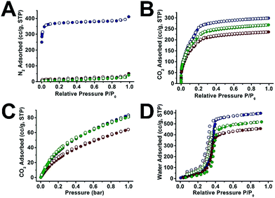 | ||
| Fig. 4 N2 sorption isotherms at 77 K (A), CO2 sorption isotherms at 195 K (B) and 273 K (C), and water vapor sorption isotherms at 298 K (D) of UiO-66 (navy), UiO-66@xPS (red) and UiO-66@xPBA (green). UiO-66@xPS and UiO-66@xPBA isotherms were normalized by subtracting the mass of the polymer (Table S5†). | ||
Interestingly, the water vapor sorption isotherms at 298 K show similar pore filling pressure suggesting that the pore environment of UiO-66 was largely unchanged after polymer coating. The water adsorption capacity of UiO-66@xPS and UiO-66@xPBA is slightly lower than that of UiO-66. This agrees well with the 195 K CO2 adsorption results. Meanwhile, the fact that UiO-66@xPS and UiO-66@xPBA can adsorb water also indicates that the hydrophobic PS or PBA coatings cannot block the entry of water vapor (Fig. 4D). This is contradictory to several examples in the literature where hydrophobic coatings can selectively adsorb CO2 over H2O.47–49 According to the physical properties of these two small molecules, H2O has a kinetic diameter of 2.65 Å which is significantly smaller than that of CO2 (3.3 Å). Indeed, the permeability of H2O in common polymeric materials is usually significantly higher than that of CO2.50 Therefore, it is not surprising that the inner porosity of UiO-66 was fully accessible by both guest molecules despite the presence of a dense PS coating.
Controlling MOF surface wettability
Next, we turned to demonstrate the ability to control the MOF surface wettability through polymer coating. Static water contact angle (CA) experiments show that neat UiO-66 exhibited a CA of 29 ± 3° (Fig. 5A). Applying a hydrophilic poly(hydroxyethyl acrylate) (PHEA) coating to UiO-66 afforded UiO-66@xPHEA with a CA of 0° (Fig. 5B). Switching PHEA with poly(n-butylacrylate) (UiO-66@xPBA) and PS (UiO-66@xPS) led to an increase of CA to 97 ± 1° and 134 ± 1°, respectively (Fig. 5C and D). Ultimately, by applying a poly(1H,1H,2H,2H-perfluorodecyl methacrylate) (PPFMA) coating, UiO-66@xPPFMA exhibited a CA of 158 ± 1°, marking itself as a superhydrophobic material (Fig. 5F). It is worth noting that by mixing two monomers with different hydrophilic–lipophilic balance (HLB) values, intermediate wettability can be easily achieved. UiO-66@xP(BzMA-co-PFMA) (BzMA is benzyl methacrylate) is such an example as we intentionally blended BzMA and PFMA achieving a CA of 148 ± 2°, falling within the bracket of that of UiO-66@xPS and UiO-66@xPPFMA (Fig. 5E). (Additional TEM images of these composite particles are shown in Fig. S26–29†.)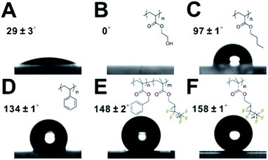 | ||
| Fig. 5 Water contact angle measurement for UiO-66 (A), UiO-66@PHEA (B), UiO-66@xPBA (C), UiO-66@xPS (D), UiO-66@xP(BzMA-co-PFMA) (E), and UiO-66@xPPFMA (F). | ||
Improving MOF stability against aggressive chemicals
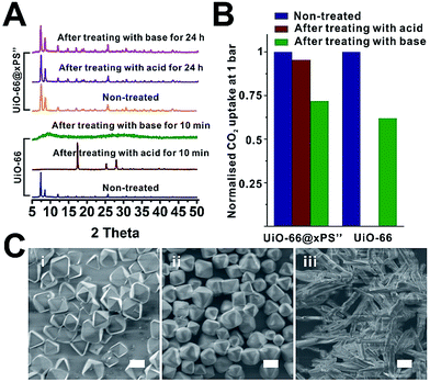
Water and chemical stability has long been a major concern that, to some extent, limits the real-world deployment of many MOF materials despite their intriguing properties. Recently, there has been an increasing effort to protect MOFs through surface modification with hydrophobic moieties. For instance, Jiang and Zhu et al. demonstrated that the water stability of MOF-5, HKUST-1, ZIF-67 and NH2-MIL-125(Ti) can be significantly improved through surface modification with organosilicones.47,51 Ma et al. recently reported that surface modification of MOFs with hydrophobic small molecules such as 1H,1H,2H,2H-perfluorodecanethiol49 and n-octadecylphosphonic acid52 can also enhance the water and chemical stability of MOFs. However, shielding MOFs from strong acids and bases requires a dense yet robust coating which, to the best of our knowledge, has not been achieved so far. Therefore, we are keen to investigate how a rationally designed polymer coating can improve the water stability of the MOF core.To demonstrate, the chemical stability of neat UiO-66 was compared with that of UiO-66@xPS′′ which contained a 7 ± 1 nm poly(styrene-co-divinylbenzene) coating (Fig. S30†). After treating both samples with 1 M NaOH and 1 M H2SO4 at 50 °C, neat UiO-66 completely lost its crystallinity after 10 min treatment in both cases whereas UiO-66@xPS′′ shows no apparent changes even after 24 h treatment (Fig. 6A). The SEM images show that acid or base treated UiO-66@xPS′′ exhibits no observable morphological changes (Fig. 6C). Neat UiO-66, however, completely lost its original morphology after H2SO4 treatment (Fig. 6Ciii).
CO2 uptake at 195 K was used to quantitatively evaluate the stability of two materials. H2SO4 and NaOH treated UiO-66@xPS′′ adsorbed 235 cm3 g−1 and 176 cm3 g−1 CO2 at 1 bar, accounting for 96% and 72% of the CO2 uptake values of the non-treated one indicating that the porosity was largely retained. Neat UiO-66, however, only shows 0.3 cm3 g−1 CO2 uptake after 10 min H2SO4 treatment indicating the complete loss of porosity (Fig. 6B, S36 and S37†). NaOH treated UiO-66, as an exception, did not show apparent morphological changes (Fig. S31B†) or complete loss of porosity (Fig. 6B) despite the complete loss of crystallinity. This is likely due to the low solubility of Zr complexes in NaOH aqueous solution thereby inhibiting its macroscopic morphological transformation. Indeed, the N2 sorption isotherm of NaOH treated UiO-66 at 77 K shows a significant reduction of micropore uptake due to increased mesopore uptake compared to that of neat UiO-66 (Fig. S38†), indicating its disordered pore structure. Nevertheless, these results all suggested that a uniform 7 nm PS coating can effectively reduce the diffusion of aggressive chemicals to the MOF core thereby significantly prolonging the stability of the MOF.
Conclusions
In summary, we developed a new approach for the fabrication of MOF@polymer functional composites using SI-ATRP. Using a rationally designed RCP, this generalizable approach overcomes the limitations of traditional covalent linkage-based SI-ATRP and was successfully applied to MOFs with no apparent functional moieties. Moreover, the thickness, functionality, sequence of the polymer shell and the wettability of the final composite materials can be systematically tuned. We demonstrated that the polymer coatings are surface specific and do not affect the inherent porosity of the MOFs. Finally, we demonstrated that UiO-66 coated with a 7 nm PS shell was able to withstand 1 M H2SO4 and 1 M NaOH treatment at 50 °C up to 1 day without a significant loss of crystallinity, morphology or porosity. We envision that this powerful method will lead to the discovery of a wide spectrum of MOF@polymer functional composites with controllable structural parameters and surface properties thus opening new opportunities in fundamental science and real-world deployment of MOF materials.Conflicts of interest
There are no conflicts to declare.Acknowledgements
Part of the TEM work was performed at the National Center for Protein Science, Shanghai. This work made use of the resources of the Instrumental Analysis Center and the Centre for High-resolution Electron Microscopy (CħEM) of SPST at ShanghaiTech University. This work was supported by the Shanghai Pujiang Program, China (Grant No. 16PJ1406700), National Natural Science Foundation of China (Grant No. 21701110) and the start-up funding from ShanghaiTech University.Notes and references
- B. Dubertret, P. Skourides, D. J. Norris, V. Noireaux, A. H. Brivanlou and A. Libchaber, Science, 2002, 298, 1759–1762 CrossRef CAS PubMed.
- H. Y. Kim, D. E. Yoon, J. Jang, D. Lee, G. M. Choi, J. H. Chang, J. Y. Lee, D. C. Lee and B. S. Bae, J. Am. Chem. Soc., 2016, 138, 16478–16485 CrossRef CAS PubMed.
- W. U. Huynh, J. J. Dittmer and A. P. Alivisatos, Science, 2002, 295, 2425–2427 CrossRef CAS PubMed.
- M. A. Boles, M. Engel and D. V. Talapin, Chem. Rev., 2016, 116, 11220–11289 CrossRef CAS PubMed.
- P. D. Howes, R. Chandrawati and M. M. Stevens, Science, 2014, 346, 1247390 CrossRef PubMed.
- C. Chevigny, F. Dalmas, E. Di Cola, D. Gigmes, D. Bertin, F. o. Boué and J. Jestin, Macromolecules, 2011, 44, 122–133 CrossRef CAS.
- H. Furukawa, K. E. Cordova, M. O'Keeffe and O. M. Yaghi, Science, 2013, 341, 1230444 CrossRef PubMed.
- S. Kitagawa, R. Kitaura and S. Noro, Angew. Chem., Int. Ed., 2004, 43, 2334–2375 CrossRef CAS PubMed.
- G. Ferey, Chem. Soc. Rev., 2008, 37, 191–214 RSC.
- K. Sumida, D. L. Rogow, J. A. Mason, T. M. McDonald, E. D. Bloch, Z. R. Herm, T. H. Bae and J. R. Long, Chem. Rev., 2012, 112, 724–781 CrossRef CAS PubMed.
- J. R. Li, R. J. Kuppler and H. C. Zhou, Chem. Soc. Rev., 2009, 38, 1477–1504 RSC.
- J. Lee, O. K. Farha, J. Roberts, K. A. Scheidt, S. T. Nguyen and J. T. Hupp, Chem. Soc. Rev., 2009, 38, 1450–1459 RSC.
- J. Della Rocca, D. Liu and W. Lin, Acc. Chem. Res., 2011, 44, 957–968 CrossRef CAS PubMed.
- M. Sindoro, N. Yanai, A. Y. Jee and S. Granick, Acc. Chem. Res., 2014, 47, 459–469 CrossRef CAS PubMed.
- L. Wang, W. Wang, X. Zheng, Z. Li and Z. Xie, Chem. - Eur. J., 2017, 23, 1379–1385 CrossRef CAS PubMed.
- M. D. Rowe, D. H. Thamm, S. L. Kraft and S. G. Boyes, Biomacromolecules, 2009, 10, 983–993 CrossRef CAS PubMed.
- P. Horcajada, R. Gref, T. Baati, P. K. Allan, G. Maurin, P. Couvreur, G. Ferey, R. E. Morris and C. Serre, Chem. Rev., 2012, 112, 1232–1268 CrossRef CAS PubMed.
- C. He, D. Liu and W. Lin, Chem. Rev., 2015, 115, 11079–11108 CrossRef CAS PubMed.
- P. Horcajada, T. Chalati, C. Serre, B. Gillet, C. Sebrie, T. Baati, J. F. Eubank, D. Heurtaux, P. Clayette, C. Kreuz, J. S. Chang, Y. K. Hwang, V. Marsaud, P. N. Bories, L. Cynober, S. Gil, G. Ferey, P. Couvreur and R. Gref, Nat. Mater., 2010, 9, 172–178 CrossRef CAS PubMed.
- W. Wang, L. Wang, Y. Li, S. Liu, Z. Xie and X. Jing, Adv. Mater., 2016, 28, 9320–9325 CrossRef CAS PubMed.
- Y. D. Zhu, S. P. Chen, H. Zhao, Y. Yang, X. Q. Chen, J. Sun, H. S. Fan and X. D. Zhang, ACS Appl. Mater. Interfaces, 2016, 8, 34209–34217 CrossRef CAS PubMed.
- W.-H. Chen, W.-C. Liao, Y. S. Sohn, M. Fadeev, A. Cecconello, R. Nechushtai and I. Willner, Adv. Funct. Mater., 2018, 28, 1705137 CrossRef.
- Z. Wang, D. Wang, S. Zhang, L. Hu and J. Jin, Adv. Mater., 2016, 28, 3399–3405 CrossRef CAS PubMed.
- K. Xie, Q. Fu, J. Kim, H. Lu, Y. He, Q. Zhao, J. Scofield, P. A. Webley and G. G. Qiao, J. Membr. Sci., 2017, 535, 350–356 CrossRef CAS.
- G. Huang, Q. Yang, Q. Xu, S. H. Yu and H. L. Jiang, Angew. Chem., Int. Ed., 2016, 55, 7379–7383 CrossRef CAS PubMed.
- Y. Peng, M. Zhao, B. Chen, Z. Zhang, Y. Huang, F. Dai, Z. Lai, X. Cui, C. Tan and H. Zhang, Adv. Mater., 2018, 30, 1705454 CrossRef PubMed.
- T. Kitao, Y. Zhang, S. Kitagawa, B. Wang and T. Uemura, Chem. Soc. Rev., 2017, 46, 3108–3133 RSC.
- C. V. McGuire and R. S. Forgan, Chem. Commun., 2015, 51, 5199–5217 RSC.
- C. M. Hui, J. Pietrasik, M. Schmitt, C. Mahoney, J. Choi, M. R. Bockstaller and K. Matyjaszewski, Chem. Mater., 2014, 26, 745–762 CrossRef CAS.
- K. A. McDonald, J. I. Feldblyum, K. Koh, A. G. Wong-Foy and A. J. Matzger, Chem. Commun., 2015, 51, 11994–11996 RSC.
- K. Xie, Q. Fu, Y. He, J. Kim, S. J. Goh, E. Nam, G. G. Qiao and P. A. Webley, Chem. Commun., 2015, 51, 15566–15569 RSC.
- H. Liu, H. Zhu and S. Zhu, Macromol. Mater. Eng., 2015, 300, 191–197 CrossRef CAS.
- S. Dong, Q. Chen, W. Li, Z. Jiang, J. Ma and H. Gao, J. Mater. Chem. B, 2017, 5, 8322–8329 RSC.
- H. Sun, B. Tang and P. Wu, ACS Appl. Mater. Interfaces, 2017, 9, 21473–21484 CrossRef CAS PubMed.
- K. Xie, Q. Fu, C. Xu, H. Lu, Q. Zhao, R. Curtain, D. Gu, P. A. Webley and G. G. Qiao, Energy Environ. Sci., 2018, 11, 544–550 RSC.
- K. Xie, Q. Fu, P. A. Webley and G. G. Qiao, Angew. Chem., Int. Ed., 2018, 57, 8597–8602 CrossRef CAS PubMed.
- K. Matyjaszewski, S. G. Gaynor, A. Kulfan and M. Podwika, Macromolecules, 1997, 30, 5192–5194 CrossRef CAS.
- X. Huang and M. J. Wirth, Anal. Chem., 1997, 69, 4577–4580 CrossRef CAS.
- K. Matyjaszewski and N. V. Tsarevsky, Nat. Chem., 2009, 1, 276–288 CrossRef CAS PubMed.
- W. A. Braunecker and K. Matyjaszewski, Prog. Polym. Sci., 2007, 32, 93–146 CrossRef CAS.
- Y. K. Chong, G. Moad, E. Rizzardo and S. H. Thang, Macromolecules, 2007, 40, 4446–4455 CrossRef CAS.
- G. Lu, C. Cui, W. Zhang, Y. Liu and F. Huo, Chem. - Asian J., 2013, 8, 69–72 CrossRef CAS PubMed.
- J. Cravillon, R. Nayuk, S. Springer, A. Feldhoff, K. Huber and M. Wiebcke, Chem. Mater., 2011, 23, 2130–2141 CrossRef CAS.
- H. Hu, B. Guan, B. Xia and X. W. Lou, J. Am. Chem. Soc., 2015, 137, 5590–5595 CrossRef CAS PubMed.
- A. Knebel, S. Friebe, N. C. Bigall, M. Benzaqui, C. Serre and J. Caro, ACS Appl. Mater. Interfaces, 2016, 8, 7536–7544 CrossRef CAS PubMed.
- L. Bromberg, Y. Diao, H. Wu, S. A. Speakman and T. A. Hatton, Chem. Mater., 2012, 24, 1664–1675 CrossRef CAS.
- W. Zhang, Y. Hu, J. Ge, H. L. Jiang and S. H. Yu, J. Am. Chem. Soc., 2014, 136, 16978–16981 CrossRef CAS PubMed.
- C. A. Fernandez, S. K. Nune, H. V. Annapureddy, L. X. Dang, B. P. McGrail, F. Zheng, E. Polikarpov, D. L. King, C. Freeman and K. P. Brooks, Dalton Trans., 2015, 44, 13490–13497 RSC.
- Q. Sun, H. He, W. Y. Gao, B. Aguila, L. Wojtas, Z. Dai, J. Li, Y. S. Chen, F. S. Xiao and S. Ma, Nat. Commun., 2016, 7, 13300 CrossRef CAS PubMed.
- S. M. Allen, M. Fujii, V. Stannett, H. B. Hopfenberg and J. L. Williams, J. Membr. Sci., 1977, 2, 153–163 CrossRef CAS.
- X. Qian, F. Sun, J. Sun, H. Wu, F. Xiao, X. Wu and G. Zhu, Nanoscale, 2017, 9, 2003–2008 RSC.
- Y. Sun, Q. Sun, H. Huang, B. Aguila, Z. Niu, J. A. Perman and S. Ma, J. Mater. Chem. A, 2017, 5, 18770–18776 RSC.
Footnote |
| † Electronic supplementary information (ESI) available. See DOI: 10.1039/c8sc03520b |
| This journal is © The Royal Society of Chemistry 2019 |

