Destabilisation of Ca(BH4)2 and Mg(BH4)2via confinement in nanoporous Cu2S hollow spheres†
Qiwen
Lai
and
Kondo-Francois
Aguey-Zinsou
 *
*
Merlin Group, School of Chemical Engineering, The University of New South Wales, Sydney, NSW 2052, Australia. E-mail: f.aguey@unsw.edu.au
First published on 25th May 2017
Abstract
Complex borohydrides of calcium (Ca(BH4)2) and magnesium (Mg(BH4)2) have gained increasing attention as promising hydrogen storage materials due to their high volumetric and gravimetric density. However, these borohydrides suffer from high desorption temperatures and poor hydrogen reversibility. In this study, Ca(BH4)2 and Mg(BH4)2 were confined within the porosity of Cu2S hollow spheres. Upon confinement, hydrogen was released at a temperature as low as 50 °C and full hydrogen release was completed by 300 °C. Upon cycling at 300 °C and 6 MPa H2 pressure, some hydrogen uptake of 0.9 and 0.5 mass% was achieved for these composite materials, i.e. Ca(BH4)2@Cu2S and Mg(BH4)2@Cu2S, respectively. Partial rehydrogenation was confirmed by FTIR proving the regeneration of borohydride phases. The nature of these improvements was studied through comparison to the physical mixture of borohydrides and Cu2S hollow spheres, and the results confirmed the effect of nanoconfinement in facilitating the destabilisation of Ca(BH4)2 and Mg(BH4)2. These results confirm that a well-designed nanoporous structure confining the decomposition products of borohydrides during hydrogen release could potentially lead to high reversible hydrogen storage material.
1. Introduction
Hydrogen has the potential to become a universal energy carrier enabling the effective use of renewable energy while providing reliability for a range of applications including vehicles. However, the safe and efficient use of hydrogen remains hindered by the lack of appropriate storage materials with both high reversible volumetric and gravimetric storage density. In this context, metal borohydrides have been identified as potential hydrogen stores. However, the high hydrogen release temperature and irreversibility issues associated with these materials have limited progress.1,2 The Group I borohydride NaBH4 has been extensively investigated for hydrogen release via hydrolysis but it is only recently that high reversible capacity has been demonstrated.3 LiBH4 showed some reversibility at temperatures above 600 °C at 15–35 MPa hydrogen pressure,4 and upon nanoconfinement, reversibility was achieved under milder conditions (320 °C and 4 MPa)5 but with an overall low storage capacity.Within the Group II of borohydrides, Ca(BH4)2 and Mg(BH4)2 are particularly interesting because they can theoretically store 11.6 and 14.9 mass% of hydrogen, and they exhibit an enthalpy change of −32 kJ mol−1 H2 and −39 kJ mol−1 H2, respectively.4,6 Such low enthalpies could potentially enable hydrogen desorption at around room temperature. However, for both borohydrides, hydrogen release is observed at relative high temperatures (300–500 °C) after melting and through complicated multi-step reaction paths simplified according to the following competing pathways:
| 6Ca(BH4)2 → 2CaB12H12 + 5CaH2 + 13H2, 6.3 mass% H2ca. 330 °C | (1a) |
| 3Ca(BH4)2 → 2CaH2 + 1CaB6 + 10H2, 9.6 mass% H2ca. 330 °C | (1b) |
| 6Mg(BH4)2 → MgB12H12 + 5MgH2 + 13H2, 8.1 mass% H2 > 350 °C | (2a) |
| Mg(BH4)2 → MgB2 + 4H2, 14.9 mass% H2 > 450 °C | (2b) |
The decomposition of Ca(BH4)2 is particularly complex involving polymorphic phase transitions and the formation of unknown intermediate phases.4,6 Addition of TiCl3 showed 3.8 mass% reversibility at 9 MPa and 350 °C.7 Ball milling the decomposition products CaH2 and CaB6 with TiF3 also showed up to 19% generation of Ca(BH4)2.8 Higher yields (up to 60%) require harsher conditions of 400–440 °C and 70 MPa hydrogen pressure.9 More recently, nanoconfinement of Ca(BH4)2 in mesoporous carbon scaffold via wet method was investigated by Comănescu et al.,10 and 2.4 mass% of hydrogen was reabsorbed under 4.5 MPa and non-isothermal conditions of 550 °C. However, the regeneration of Ca(BH4)2 was not proven. The agglomeration of particles during melting, formation of stable intermediates such as CaB12H12, and the release of dodecaborane (B12H12) during the hydrogen desorption still remain the main problems restricting reversibility.11
The decomposition of Mg(BH4)2 is similarly complicated as it involves a variety of Mg–B–H ternary intermediates including Mg(B3H8)2 (ref. 12) and MgB12H12 (ref. 13) appearing under different conditions of desorption temperatures and atmospheres/back pressures.4 The partial decomposition of Mg(BH4)2 into Mg(B3H8)2 can be reversed at 250 °C and 12 MPa of hydrogen. Direct rehydrogenation of MgB2 requires high temperatures and pressures (e.g. 400 °C and 95 MPa).14 Upon nanoconfinement in a carbon aerogel traces of MgBH4 were observed under milder rehydrogenation conditions (e.g. 270 °C and 15 MPa) but with some decay of the hydrogen desorption properties and the release of B2H6.15 Ammonization is also an effective route to exploit the hydrogen properties of borohydrides including Ca(BH4)2 and Mg(BH4)2 to lead to new reactive hydrides for the release of hydrogen at low temperatures.16–18 For example, due to the introduction of an ammonia ligand Mg(BH4)2·(NH3)2(NH3BH3) released 9.6 mass 5 of hydrogen at 170 °C.17 However, rehydrogenation of these reactive hydrides is limited.
Unlike conventional approaches such as doping/catalyst addition or destabilization through partial cation substitution or reaction with another hydride, nanoconfinement can simultaneously improve both the thermodynamic and kinetic properties of hydride materials. The hydrides are destabilized due to excess surface energy and contributions from the hydride/porous host interface leading to improved thermodynamics, and diffusion distances are decreased leading to improved kinetics.1,19 However, the use of carbon supports for nanoconfinement tends to lead to limited reversibility owing oxygen groups at carbons' surface.20 The later oxidise the hydrides during hydrogen cycling.21 In this study, we have investigated the possibility to nanoconfine Ca(BH4)2 and Mg(BH4)2 in alternative copper sulphide hollow structures (denoted Cu2S). The later are stable above 400 °C for hydrogen cycling,21 and can potentially lead to a destabilisation of borohydrides through the formation of less stable sulphurated borohydrides.22
2. Materials and method
All operations were carried out under inert atmosphere in an argon-filled LC-Technology glove box (<1 ppm O2 and H2O).2.1 Materials
Copper(II) sulphate (CuSO4, anhydrous), sodium hydroxide (NaOH) and calcium chloride (CaCl2, anhydrous) were purchased from Ajax Finechem. Polyvinylpyrrolidone (PVP K30, MW ∼ 40![[thin space (1/6-em)]](https://www.rsc.org/images/entities/char_2009.gif) 000) was purchased from Fluka Analytical. Hydrazine hydrate (N2H4·H2O, 80%) was purchased from Merck. Thioacetamide (CH3CSNH2) was purchased from BDH. Sodium borohydride (NaBH4, 99%), dibutyl magnesium (Mg(C4H9)2, 1.0 M in heptane) and borane dimethyl sulphide complex ((CH3)2SBH3, 2.0 M in toluene) were purchased from Sigma-Aldrich. Tetrahydrofuran (THF) was purchased as HPLC grade from Fisher Scientific and dried using a LC Technology SP-1 Solvent Purification System. All other chemicals were used without further purification.
000) was purchased from Fluka Analytical. Hydrazine hydrate (N2H4·H2O, 80%) was purchased from Merck. Thioacetamide (CH3CSNH2) was purchased from BDH. Sodium borohydride (NaBH4, 99%), dibutyl magnesium (Mg(C4H9)2, 1.0 M in heptane) and borane dimethyl sulphide complex ((CH3)2SBH3, 2.0 M in toluene) were purchased from Sigma-Aldrich. Tetrahydrofuran (THF) was purchased as HPLC grade from Fisher Scientific and dried using a LC Technology SP-1 Solvent Purification System. All other chemicals were used without further purification.
2.2 Synthesis of the Cu2S hollow spheres
Cu2S hollow spheres were synthesized through a sacrificial template method based on Kirkendall diffusion scaled up from the procedure by Zhu et al.,23 following the proposed reaction steps below (Scheme 1):| 4Cu2+ + 8OH− + N2H4 → 2Cu2O + 6H2O + N2 | (3) |
| CH3CSNH2 + 3OH− → CH3COO− + NH3 + S2− + H2O | (4) |
| 2Cu2O + 2S2− + O2 + 4H2O → 2Cu2S + 8OH− | (5) |
 | ||
| Scheme 1 Illustration of the synthesis process of the Cu2S hollow spheres and the impregnation of the borohydrides within the hollow structure. | ||
At high sulphur content reaction (5) may also lead to CuS instead of Cu2S. In this procedure, the Cu2S spheres produced may also contain a mixture of Cu2S and Cu metallic, owing to the competing reduction reaction of Cu2SO4 with hydrazine hydrate during the first reaction step.24 In a typical synthesis, a solution of Cu2SO4 was prepared by dissolving 0.319 g of CuSO4 in 150 mL milli-Q water. 19.2 g PVP was added to act as a surfactant. 150 mL NaOH solution with pH of 10 and 0.2 mL of a 4 M N2H4·H2O solution were then added to oxidize the copper ions to copper oxide. 0.799 g thioacetamide was added to the solution and aged for 1 h to react with copper oxide and form copper sulphide hollow spheres. The resulting solution was centrifuged to obtain a black precipitate, which was washed with distilled water three times to remove the solvent residue, then with absolute ethanol three times to remove the water content. The solid was then dried under vacuum at room temperature for at least 12 h. BET measurement was performed using a Micromeritics TriStar 3000 Analyser from Micrometrics Instrument Corporation.
2.3 Synthesis of bulk borohydrides M(BH4)2 with M = Ca, Mg
Bulk Ca(BH4)2 and Mg(BH4)2 were synthesized by using the methods reported by Brown et al.25 and Zanella et al.,26 respectively. For Ca(BH4)2, 190 mg of NaBH4 solid and 280 mg of CaCl2 solid were grinded and added in a small round bottom flask. 15 mL of THF was then added to the flask and the solution was aged at 40 °C under magnetic stirring at 500 rpm for at least 24 h. The resulting solution was centrifuged at room temperature to remove the solid. The filtrate was placed on a Schlenk flask under vacuum to remove the THF solvent. The resulting white solid product was then dried under vacuum at 130 °C for at least 12 h.For Mg(BH4)2, 18 mL of (CH3)2SBH3 (2.0 M in toluene solution) was added in a round bottom flask. 10 mL of 1.0 M Mg(C4H9)2 in heptane solution was added into a dropping funnel. The Mg(C4H9)2 solution was then added dropwise in the (CH3)2SBH3 solution, while stirring at 500 rpm. The solution was aged for 2 h at room temperature and then centrifuged to obtain a white precipitate. The later was washed with toluene twice to remove any excess of the borane compound. The resulting solid was dried under vacuum at room temperature for at least 12 h and then at 160 °C for a further 12 h.
2.4 Impregnation of the borohydrides in the Cu2S spheres (M(BH4)2@Cu2S)
The borohydrides were introduced into the Cu2S spheres via wet impregnation method (Scheme 1). Borohydride solutions were prepared by suspending 70 mg of Ca(BH4)2 in 2 mL THF and 135 mg of Mg(BH4)2 in 5 mL THF. The Cu2S spheres were further dried under high vacuum at 200 °C. The desired solution (0.2 mL for Ca(BH4)2) and (0.4 mL for Mg(BH4)2) was then added to 20 mg of the evacuated Cu2S spheres and dried under vacuum at room temperature for at least 18 h to allow the impregnation of the borohydrides. The resulting powders were dark grey and denoted Ca(BH4)2@Cu2S and Mg(BH4)2@Cu2S and were expected to contain 2.5 and 5.2 mass% of hydrogen, respectively.2.5 Physical mixing of borohydrides with Cu2S spheres (M(BH4)2 + Cu2S)
190 mg of Ca(BH4)2 and Mg(BH4)2 solid were respectively mixed with 10 mg of dried Cu2S hollow spheres to lead to a mixture of borohydride containing 5 mass% of Cu2S. To replicate the high ratio of Cu2S upon nanoconfinement, physical mixtures 70 mass% of Cu2S in borohydride were also prepared. The mixtures were manually grinded in agate mortar to obtain a uniform light grey solid. Decomposition of the borohydride/Cu2S mixtures at different temperatures was carried out at 10 °C min−1 under an argon flow of 20 mL min−1.2.6 Characterization
The size, morphology, Energy Dispersive X-ray Spectroscopy (EDS) analysis and elemental mapping was performed by Scanning Electron Microscopy (SEM) using a FEI Nova NanoSEM 450 FE-SEM and by Transmission Electron Microscopy (TEM) and Scanning Transmission Electron Microscopy (STEM) using a Philips CM200 operated at 200 keV. For TEM analysis, the materials were grinded and dispersed in cyclohexane, sonicated for a few seconds and then dropped onto a carbon coated copper grid.The crystalline nature of the materials was determined by X-ray Diffraction (XRD) using a Philips X'pert Multipurpose XRD system operated at 40 mA and 45 kV with a monochromated Cu Kα radiation (λ = 1.541 Å) – step size = 0.01, 0.02 or 0.05, time per step = 10 or 20 s step−1. The materials were protected against oxidation from air by a Kapton foil.
Thermogravimetric Analysis (TGA) and Differential Scanning Calorimetry (DSC) in conjunction with Mass Spectrometry (MS) were conducted at 10 °C min−1 under an argon flow of 20 mL min−1 using a Mettler Toledo TGA/DSC 1 coupled with an Omnistar MS. Masses between m/z = 2 and 100 were followed. Infrared spectra were collected by Diffuse Reflectance Infrared Fourier Transform Spectroscopy (DRIFTS). Prior to measurements, the materials were diluted with synthetic mono-crystalline diamond powder (∼1 μm, Sigma-Aldrich) and loaded in an air-tight dome in an argon filled glove box to avoid any exposure of the material to air. The air-tight sample holder was then installed on a Harrick Praying Mantis Diffuse Reflection accessory installed in a Brüker VERTEX 70v FTIR spectrometer. Spectra were collected with a resolution of 2 cm−1.
Hydrogen desorption kinetics were characterized using a high pressure magnetic balance of 1 μg resolution equipped with capability for simultaneous density measurements (Rubotherm). The material was first cycled once at 100 and 200 °C to allow a gradual dehydrogenation before cycling at 300 °C. Around 30 mg of material was used and a hydrogen pressure of 6 MPa for absorption and 0.01 MPa for desorption. Hydrogen uptake and release were determined from the weight changes. For an accurate determination of the amount of hydrogen stored, a blank measurement with the empty sample holder was performed to determine the mass and volume of the sample holder. Further measurements were performed under a helium atmosphere with the material fully desorbed to determine the density of the materials and corresponding parameters for buoyancy corrections.
3. Results and discussion
3.1 Confinement of M(BH4)2@Cu2S
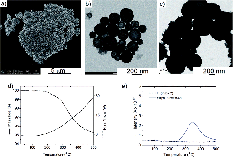
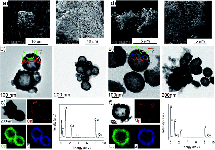
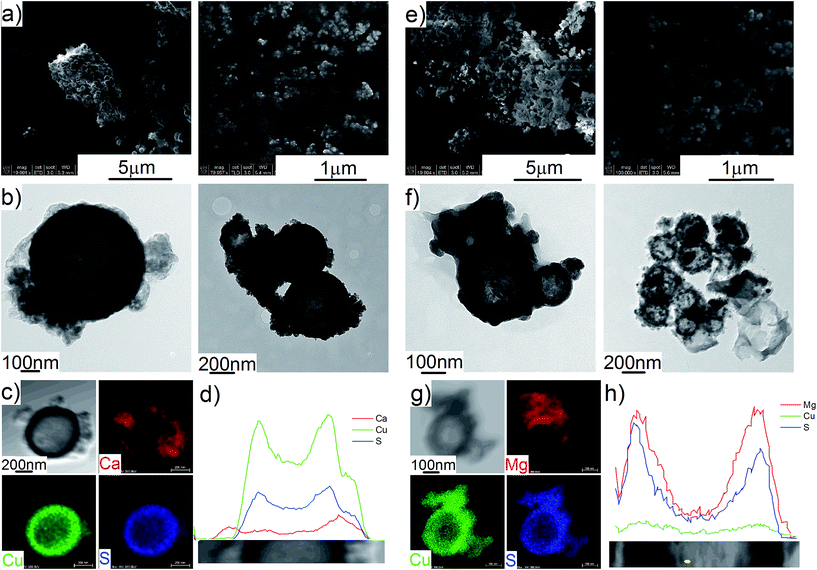
The Cu2S spheres produced were effectively hollow with a particle size ranging from 100 to 800 nm (Fig. 1a and b), with an average wall thickness of 35 nm. The decrease in intensity observed toward the centre of the individual spheres confirmed their hollow structure as per previous reports.21,23 Furthermore, these hollow spheres were found to be stable up to 500 °C (Fig. 1c) and this was confirmed by thermal analysis coupled with mass spectrometry showing some weight loss around 300 °C with the concomitant release of sulphur. This was attributed to the conversion of residual CuS into Cu2S in the material (Fig. 1d and e).27 The pore-volume of these Cu2S hollow spheres is 0.128 cm3 g−1, the surface area 14 m2 g−1 and the average pore width 20 nm.21 This means that the wall of the hollow spheres is nanoporous and thus can facilitate the nanoconfinement of borohydrides through impregnation methods.After impregnation with Ca(BH4)2 and Mg(BH4)2 (Scheme 1) little changes in morphology were observed by SEM and TEM (Fig. 2). However in STEM, elemental mapping revealed that Ca and Mg were clearly overlapping with the Cu and S signals (Fig. 2c and f) in agreement with the elemental line scan analysis showing Ca and Mg throughout the Cu2S particles (Fig. 2b and e). This confirmed that Ca(BH4)2 and Mg(BH4)2 were successfully impregnated inside the hollow spheres. Additional characterisation of the confined borohydrides by XRD did not reveal any phases related to Ca(BH4)2 or Mg(BH4)2, but solely diffraction peaks assigned to the Cu2S and Cu phases corresponding to the Cu2S hollow spheres (Fig. 3).21,23 As previously discussed, this mixture of Cu2S and Cu phases is inherent to the synthetic approach used for the preparation of the hollow spheres.24 The lack of observable diffraction peaks for the confined borohydrides suggested that the borohydrides were in an amorphous state or their crystallite size was too small to be detected and this further supported the STEM results. Similar observations have been made for Mg(BH4)2 and LiBH4 confined in porous carbons and silica, and these were attributed to a decrease in the long-range order of the hydrides due to their nanosize.5,15
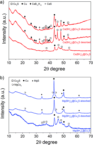 | ||
| Fig. 3 XRD pattern of as-synthesised, after hydrogen desorption and absorption at 300 °C (a) Ca(BH4)2@Cu2S and (b) Mg(BH4)2@Cu2S. | ||
3.2 Hydrogen properties of M(BH4)2@Cu2S
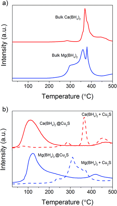
The hydrogen desorption profiles of the as-synthesised materials were first determined by MS (Fig. 4). As compared to bulk Ca(BH4)2 which released hydrogen above 300 °C, hydrogen desorption started from 50 °C through a main peak ending at around 300 °C for Ca(BH4)2@Cu2S (Fig. 4a and b). A similar result was obtained for Mg(BH4)2@Cu2S with some minor hydrogen release above 400 °C attributed to a possible reaction between Mg(BH4)2 and Cu2S. The incorporation of Ca(BH4)2 and Mg(BH4)2 within the Cu2S hollow sphere thus led to a significant improvement with respect to the initial hydrogen release. Such an improvement may also be due to a metathesis reaction of Cu2S leading to the formation of CaS or MgS and Cu with the release of diborane (B2H6) and possibly some hydrogen sulphide (H2S). Indeed, by mass spectrometry in addition to the release of hydrogen, traces of B2H6 and H2S were observed and this further evidenced some reaction between the borohydrides and Cu2S. This was corroborated by the XRD analysis of Mg(BH4)2@Cu2S after hydrogen release at 300 °C which showed the formation of MgS and MgCu2 phases while diffraction peaks related to the Cu2S phase of the Cu2S hollow spheres disappeared (Fig. 3b). It is noteworthy that no MgB12H12, MgH2 or MgB phases were observed by XRD after hydrogen release and this again suggested some reaction between Mg(BH4)2 and Cu2S during the first hydrogen release and thus a different decomposition path for Mg(BH4)2. In contrast, the XRD pattern of Ca(BH4)2@Cu2S after hydrogen desorption at 300 °C still showed diffraction peaks corresponding to the Cu2S phase of the Cu2S hollow spheres as well as peaks attributed to the CaB12H12, CaS and Cu phases. The Cu phase was attributed to a partial reduction of Cu2S by the borohydride and/or hydrogen,28 leading to the additional CaS phase. The appearance of the CaB12H12 phase was also an indication that Ca(BH4)2 was less prone to react with the hollow structure than Mg(BH4)2. It also suggested that the decomposition of Ca(BH4)2 within the hollow Cu2S spheres may follow the decomposition path (2a) although no CaH phase was observed.5 mass% or a higher amount of 70 mass% (to replicate the high Cu2S/borohydride ratio upon confinement) of Cu2S hollow spheres physical mixed with Ca(BH4)2 or Mg(BH4)2 also lead to some reduction of the temperature for hydrogen release but not as pronounced as the decreased observed for the nanoconfined borohydrides (Fig. 4b). The main hydrogen release for Ca(BH4)2 mixed with the hollow Cu2S spheres still occurred above 350 °C. For Mg(BH4)2 mixed with hollow Cu2S spheres, hydrogen desorption started at the lower temperature of 220 °C instead of 250 °C with a more pronounced hydrogen desorption at around 300 °C (Fig. 4b). It is noteworthy that the thermal decomposition of the physical mixture of the borohydrides with Cu2S hollow spheres also led to the release of B2H6 and H2S in addition to hydrogen (Fig. S2†). This shows again that Cu2S can facilitate to some extent the decomposition of Mg(BH4)2 though a metathesis reaction and it can be hypothesized the close vicinity between the Cu2S and borohydrides upon nanoconfinement can better facilitate such a reaction.
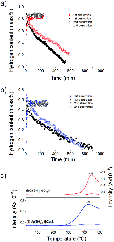
To probe the reversibility of the hydrogen release, the materials were subjected to 6 MPa hydrogen pressure at 300 °C, i.e. above the hydrogen desorption as observed after confinement (Fig. 4). Ca(BH4)2@Cu2S and Mg(BH4)2@Cu2S both absorbed hydrogen relatively quickly with full absorption achieved in less than 150 min. However, hydrogen release was slow with more than 500 min needed (Fig. 5a and b). To confirm the reversibility of the process and inform the slow dehydrogenation kinetics, the hydrogen desorption profile of both materials in the absorbed and desorbed state was further analysed by MS. As shown Fig. 5c, both materials in the absorbed state released hydrogen from 250 °C with a main peak at 445 and 425 °C, respectively. In the desorbed state only some residual hydrogen was detected and this confirmed some rehydrogenation of both materials under mild conditions of temperature and pressure. It is noteworthy that only hydrogen was detected by MS. Contrary to previous investigations,11,15 no B2H6, B12H12 or related compounds were detected and this may suggest a different decomposition path for Ca(BH4)2 and Mg(BH4)2 confined with Cu2S hollow spheres. However, as indicated by MS the low temperature desorption features of the materials as-synthesised were not retained and this explained the slow hydrogen desorption kinetics at 300 °C.
This higher desorption temperature may be explained by the reaction of the confined borohydrides with Cu2S and/or additional swelling of the molten borohydrides outside the porosity of the Cu2S hollow spheres during their initial decomposition and hydrogen release. Expulsion of the borohydrides upon melting outside the hollow structure would lead to the formation of large aggregates and a loss in reversibility because of elemental dispersion as previously observed.21 However, additional characterisation by TEM and STEM did not show any significant evolution of the Ca(BH4)2@Cu2S and Mg(BH4)2@Cu2S structures. The hollow spheres retained their morphology, and elemental mapping revealed that Ca and Mg were clearly overlapping with the Cu and S signals (Fig. 6). Accordingly, the borohydrides were still confined. Further analysis by XRD of the materials in the absorbed state did not reveal any new phases as compared to the diffraction patterns recorded for the desorbed materials (Fig. 3). However, FTIR analysis revealed the reappearance of vibrations assigned to asymmetric stretching and deformation mode of the BH4− and [B12H12]2− ions upon hydrogen absorption (Fig. 7), which proved a partial rehydrogenation after hydrogen release. Only partial rehydrogenation was reported for Ca(BH4)2 nanoconfined in mesoporous carbon at 4.5 MPa at 550 °C.10 Similarly, some rehydrogenation was achieved for MgBH4 nanoconfined in carbon aerogel at 270 °C and 15 MPa.15 The rehydrogenation observed may be assigned to a confinement effect and the close vicinity of the decomposition products. After confinement, B–H stretching modes shifted to lower wavelengths, which suggested a weakening of the B–H bond. However, after hydrogen cycling, these vibrations were found to shift back to higher wavelengths, in agreement with the higher desorption temperatures observed by MS (Fig. 5c). This may be due to the initial reaction of the borohydrides with Cu2S upon the first release of hydrogen. As shown by XRD analysis, Cu2S reacts to some extent with Ca(BH4)2 and Mg(BH4)2 to lead to their respective sulphides. This should facilitate the first desorption of hydrogen via a metathesis reaction leading to the partial substitution of (BH4)− with S, and assuming that this occurs as a solid–solid state reaction, it will result in borohydride nanoparticles embedded within a sulphide matrix.
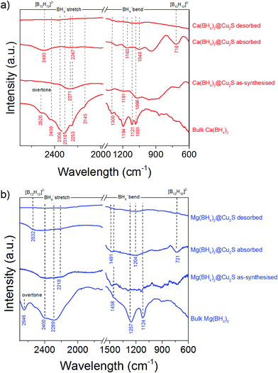 | ||
| Fig. 7 FTIR spectra of (a) Ca(BH4)2@Cu2S and (b) Mg(BH4)2@Cu2S as-synthesized, after hydrogen desorption under a pressure of 0.01 MPa at 300 °C, and after hydrogen absorption at 300 °C, compared to bulk γ-Ca(BH4)2 and bulk α-Mg(BH4)2. The spectra of γ-Ca(BH4)2,45–47 α-Mg(BH4)2 (ref. 48 and 49) as well as observed [B12H12]−2 vibrations50 are in agreement with previous observations. | ||
3.3 Hydrogen properties of M(BH4) physically mixed with Cu2S
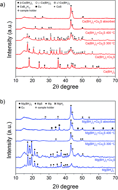
In order to clarify the effect of the Cu2S hollow spheres on the hydrogen sorption properties of Ca(BH4)2 and Mg(BH4)2 and discriminate the effect of confinement from the possible destabilisation effect of Cu2S, both borohydrides were physically mixed with Cu2S hollow spheres. Since, increasing the amount of Cu2S to 70 mass% did not significantly change the hydrogen desorption properties of the borohydrides (Fig. 4, 9, S2 and S3†), investigations focused on the mixtures containing 5 mass% of Cu2S hollow spheres as to minimise the amount of MgS and CaS formed and thus facilitate a potential the rehydrogenation of the decomposition products.As shown Fig. 8, no major changes occurred upon mixing the Cu2S hollow spheres with Ca(BH4)2 or Mg(BH4)2. The materials still had the same diffraction patterns although Ca(BH4)2 showed different polymorphs inherent to the synthesis process.29 Further analysis by coupled TGA/DSC/MS did not show any significant shift in the hydrogen desorption profile of the mixture (Fig. 4b) or thermal decomposition behaviour (Fig. 9) as compared to pristine Ca(BH4)2 and Mg(BH4)2, respectively. Full decomposition still occurred after 400 °C.
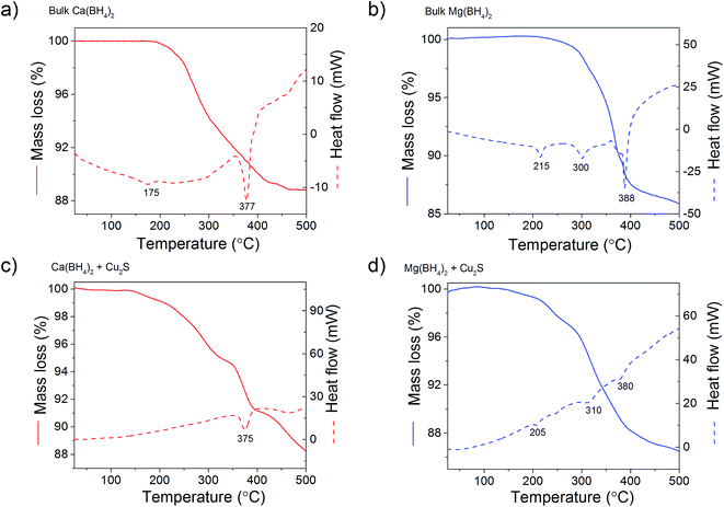 | ||
| Fig. 9 TGA/DSC profiles of (a) bulk Ca(BH4)2 and (b) its physical mixture with 5 mass% of Cu2S hollow spheres; and (c) bulk Mg(BH4)2 and (d) its physical mixture with 5 mass% of Cu2S hollow spheres. | ||
The total mass loss (11.1%) and endothermic events for pristine Ca(BH4)2 was consistent with previous reports (Fig. 9a).29,30 The endothermic event at 175 °C was assigned to the polymorphic transformation of the room temperature Ca(BH4)2 phases to β-Ca(BH4)2.29 While the second endothermic peak at 377 °C was assigned to the decomposition of β-Ca(BH4)2. For the Ca(BH4)2 + Cu2S hollow spheres mixture, as similar decomposition behaviour was observed with a reduced mass loss of 10.1% attributed to the additional 5 mass% of Cu2S hollow spheres (Fig 9b). It is unsure whether the endothermic peak observed near 377 °C for both pure Ca(BH4)2 and its mixture with Cu2S was due to the melting of Ca(BH4)2 or solely hydrogen release as this highly depends upon the hydrogen back pressure.31 However, under the current experimental conditions of flowing argon it can be assumed that Ca(BH4)2 would not melt and impregnate the Cu2S hollow spheres.
For pure Mg(BH4)2, a single mass loss of 14.0% – consistent with the theoretical hydrogen content of 14.9 mass% – and three endothermic events were observed (Fig. 9c). The endothermic peak at 225 °C was assigned to the polymeric transformation of α-Mg(BH4)2 into β-Mg(BH4)2 as per previous investigations.32 The two endothermic peaks at 300 and 388 °C were assigned to the multi-step dehydrogenation process for Mg(BH4)2 forming intermediates like MgB12H12 and MgH2.33,34 The Mg(BH4)2 + Cu2S hollow spheres mixture showed similar endothermic events indicating a similar decomposition path but with a slightly lower mass loss of 13.4% (Fig. 9d). This is consistent with the 5 mass% of Cu2S hollow spheres added to pristine Mg(BH4)2. Once again, given the complex behaviour of Mg(BH4)2,31 it was assume that its thermal decomposition under flowing argon would occur before melting.
Analysis by TEM confirmed that the hollow spheres were well dispersed within the borohydride phases (Fig. S4 and S5†). Additional STEM and line scan analysis across several hollow spheres further established that Ca and Mg were outside the hollow nanostructure (Fig. S4e and S5e†). This remained true for the mixture Ca(BH4)2 + Cu2S hollow spheres after hydrogen release at 400 °C (Fig. S6†). However for the mixture Mg(BH4)2 + Cu2S hollow spheres decomposed at 400 °C, some magnesium was found to be well incorporated within the Cu2S hollow spheres (Fig. S7†). This difference may reflect a varying wettability as the borohydrides melt.31,35 Mg(BH4)2 melting while decomposition would impregnate the Cu2S hollow spheres, while the solid products resulting from the decomposition of Ca(BH4)2 would remain outside the Cu2S porosity.
Additional analysis by XRD of the mixtures at 300 °C revealed that the γ-Ca(BH4)2 phase in the Ca(BH4)2 + Cu2S hollow spheres mixture converted to α′-Ca(BH4)2 with some partial hydrogen release concomitant with the formation of CaS (Fig. 4b and 8a). It is only after heating at 400 °C that full decomposition was achieved as confirmed by the disappearance of all the diffraction peaks related to Ca(BH4)2 (Fig. 8a). In contrast, upon heating the Mg(BH4)2 + Cu2S hollow spheres mixture at 300 °C no diffraction peaks were observed by XRD and this suggested that Mg(BH4)2 had melted before its full decomposition.34 Indeed, following the TGA/DSC/MS results (Fig. 4b, 9c and d) at 300 °C the Mg(BH4)2 + Cu2S hollow spheres mixture is only partially decomposed at this temperature. Further heating of the Mg(BH4)2 + Cu2S hollow spheres mixture at 400 °C led to the formation of magnesium as reflected by the additional diffraction peaks assigned to the hexagonal magnesium phase (Fig. 8b).
Attempts to rehydrogenate the decomposition products of the Ca(BH4)2 + Cu2S hollow spheres mixture were unsuccessful at 400 °C and 10 MPa hydrogen pressure as proven by XRD analysis (Fig. 8a). This contrasts with previous report claiming 19% regeneration upon similar conditions of temperature and pressure for a mixture of CaH2 and CaB6 doped with TiF3.8 The difference may be due to the lack of CaH2 in the decomposed Ca(BH4)2 + Cu2S hollow spheres mixture since no CaH2 was detected by XRD (Fig. 8a). However rehydrogenation of the decomposition products of the Mg(BH4)2 + Cu2S hollow spheres mixture at 400 °C and 10 MPa led to the formation of tetragonal MgH2 (α-MgH2) only, as proven by XRD analysis (Fig. 8b). Hence, the rehydrogenation of MgBH4 was not possible under these conditions in agreement with previous reports.14 It is noteworthy, that the intensity of the diffraction peaks of the rehydrogenated MgH2 phase was relatively small as compared to the Cu peak. Analysis of the diffraction pattern using the Scherrer equation led to an average MgH2 crystallite size of 41 ± 2 nm which indicates that the material may also be composed of relatively small particles corresponding to magnesium confined within the Cu2S hollow spheres as observed by TEM (Fig. S6†).
Analysis by TGA/DSC/MS of the rehydrogenated Mg(BH4)2 + Cu2S hollow spheres mixture showed that hydrogen release occurred in two steps (Fig. 10). A small amount of hydrogen was released along a first weight loss between 50 and 300 °C. At higher temperatures (>400 °C) the main hydrogen desorption occurred as expected for bulk MgH2,36,37 and confirmed by XRD analysis. These two desorption steps were thus assigned to various particle sizes since the decomposition temperature of MgH2 has been shown to be particle size dependent.37–39 Particles in the range of 2–10 nm can potentially desorb hydrogen close to room temperature,37,40 while bigger particles behaves like bulk MgH2.41 It is thus hypothesised that small magnesium particles confined within the Cu2S hollow spheres would desorb hydrogen at low temperatures while larger particles remaining within the bulk of the decomposition products of Mg(BH4)2 would behave like bulk MgH2. The use of Cu2S porous structures may thus offer a new approach to enable the reversible storage of hydrogen at low temperatures assuming that the amount of magnesium nanoconfined can be increased to enable sufficient storage capacity.
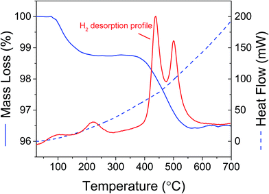 | ||
| Fig. 10 TGA/DSC/MS of Mg(BH4)2 + 5 mass% Cu2S hollow spheres mixture after decomposition at 400 °C and hydrogen at the same temperature under 6 MPa hydrogen pressure. No other gases were detected. | ||
From these results, it is also evident that simply mixing Cu2S hollow spheres with Ca(BH4)2 and Mg(BH4)2 is not sufficient to enable low hydrogen desorption temperatures and partial rehydrogenation back to the borohydride phase. The elemental products resulting from the decomposition of borohydrides during hydrogen release must be kept in close vicinity to facilitate their recombination with hydrogen. This can only be achieved through the nanoconfinement of the borohydrides before their decomposition. The low decomposition temperatures and partial reversibility observed upon confinement of Ca(BH4)2 and Mg(BH4)2 within the Cu2S hollow spheres is thus thought to be mainly related to a nanoconfinement effect rather than the partial reaction between the borohydride and Cu2S. Interfacial effects at the borohydride/porous host boundaries may also help reversibility as previously observed.42–44 Hence, if better porous structures enabling both stability of the confined phase and the decomposition products can be designed, improved reversibility for both Ca(BH4)2 and Mg(BH4)2 will be feasible.
4. Conclusions
In this study, Ca(BH4)2 and Mg(BH4)2 were successfully confined within porous Cu2S hollow spheres via solvent impregnation method. Upon confinement, hydrogen was released from 50 °C and a full hydrogen desorption was achieved below 300 °C. In contrast, physical mixing of Cu2S and the borohydrides only showed a limited effect on the hydrogen desorption properties of Ca(BH4)2 and Mg(BH4)2, with temperatures above 250 °C still required to enable significant hydrogen evolution. Accordingly, the improvements observed were attributed to the main effect of particle size reduction through the successful confinement of Ca(BH4)2 and Mg(BH4)2 within the hollow structure of Cu2S nanoparticles. The destabilisation of the borohydrides by Cu2S through their metathesis reaction may also facilitate hydrogen release. At 300 °C and under a hydrogen pressure of 6 MPa, partial rehydrogenation was observed and led to the formation of a mixture of dodecaborate and borohydride. Partial rehydrogenation of the borohydrides physically mixed with Cu2S was not possible. Accordingly, with an improved design of the host scaffold and well-controlled decomposition paths and products, confining borohydride particles within a nanosized porous metallic shell could possibly provide a better approach toward the design of high capacity hydrogen storage materials.Acknowledgements
Financial support by UNSW Internal Research Grant program is gratefully acknowledged as well as the Office of Naval Research (Award No. ONRG - NICOP - N62909-16-1-2155). We appreciate the use of instruments in the Mark Wainwright Analytical Centre at UNSW as well as equipment funded by the Australian Research Council (ARC) – Linkage, Infrastructure, Equipment and Facilities (LIEF).References
- Q. Lai, M. Paskevicius, D. A. Sheppard, C. E. Buckley, A. W. Thornton, M. R. Hill, Q. Gu, J. Mao, Z. Huang, H. K. Liu, Z. Guo, A. Banerjee, S. Chakraborty, R. Ahuja and K.-F. Aguey-Zinsou, ChemSusChem, 2015, 8, 2789–2825 CrossRef CAS PubMed.
- S.-I. Orimo, Y. Nakamori, J. R. Eliseo, A. Züttel and C. M. Jensen, Chem. Rev., 2007, 107, 4111–4132 CrossRef CAS PubMed.
- M. L. Christian and K.-F. Aguey-Zinsou, ACS Nano, 2012, 6, 7739–7751 CrossRef CAS PubMed.
- E. Rönnebro, Curr. Opin. Solid State Mater. Sci., 2011, 15, 44–51 CrossRef.
- P. Ngene, M. van Zwienen and P. E. de Jongh, Chem. Commun., 2010, 46, 8201–8203 RSC.
- M. D. Riktor, M. H. Sørby, J. Muller, E. G. Bardají, M. Fichtner and B. C. Hauback, J. Alloys Compd., 2015, 632, 800–804 CrossRef CAS.
- J.-H. Kim, S.-A. Jin, J.-H. Shim and Y. W. Cho, Scr. Mater., 2008, 58, 481–483 CrossRef CAS.
- C. Rongeat, V. D'Anna, H. Hagemann, A. Borgschulte, A. Züttel, L. Schultz and O. Gutfleisch, J. Alloys Compd., 2010, 493, 281–287 CrossRef CAS.
- E. Rönnebro and E. H. Majzoub, J. Phys. Chem. B, 2007, 111, 12045–12047 CrossRef PubMed.
- C. Comănescu, G. Capurso and A. Maddalena, Nanotechnology, 2012, 23, 385401 CrossRef PubMed.
- L.-L. Wang, D. D. Graham, I. M. Robertson and D. D. Johnson, J. Phys. Chem. C, 2009, 113, 20088–20096 CAS.
- M. Chong, A. Karkamkar, T. Autrey, S.-I. Orimo, S. Jalisatgi and C. M. Jensen, Chem. Commun., 2011, 47, 1330–1332 RSC.
- H. W. Li, K. Miwa, N. Ohba, T. Fujita, T. Sato, Y. Yan, S. Towata, M. W. Chen and S. Orimo, Nanotechnology, 2009, 20, 204013 CrossRef PubMed.
- G. Severa, E. Ronnebro and C. M. Jensen, Chem. Commun., 2010, 46, 421–423 RSC.
- Y. Yan, Y. S. Au, D. Rentsch, A. Remhof, P. E. de Jongh and A. Zuttel, J. Mater. Chem. A, 2013, 1, 11177–11183 CAS.
- Z. Tang, Y. Tan, Q. Gu and X. Yu, J. Mater. Chem., 2012, 22, 5312–5318 RSC.
- X. Chen, F. Yuan, Q. Gu and X. Yu, Dalton Trans., 2013, 42, 14365–14368 RSC.
- X. Chen, F. Yuan, Y. Tan, Z. Tang and X. Yu, J. Phys. Chem. C, 2012, 116, 21162–21168 CAS.
- F. Maximilian, Nanotechnology, 2009, 20, 204009 CrossRef PubMed.
- J. L. Figueiredo and M. F. R. Pereira, Catal. Today, 2010, 150, 2–7 CrossRef CAS.
- Q. Lai, M. Christian and K.-F. Aguey-Zinsou, Int. J. Hydrogen Energy, 2014, 39, 9339–9349 CrossRef CAS.
- J. M. Lalancette, A. Freche and R. Monteux, Can. J. Chem., 1968, 46, 2754–2757 CrossRef CAS.
- H. Zhu, J. Wang and D. Wu, Inorg. Chem., 2009, 48, 7099–7104 CrossRef CAS PubMed.
- S. V. Saikova, S. A. Vorob'ev, R. B. Nikolaeva and Y. L. Mikhlin, Russ. J. Gen. Chem., 2010, 80, 1122–1127 CrossRef CAS.
- H. C. Brown, Y. M. Choi and S. Narasimhan, Inorg. Chem., 1981, 20, 4454–4456 CrossRef CAS.
- P. Zanella, L. Crociani, N. Masciocchi and G. Giunchi, Inorg. Chem., 2007, 46, 9039–9041 CrossRef CAS PubMed.
- C. M. Simonescu, V. S. Teodorescu, O. Carp, L. Patron and C. Capatina, J. Therm. Anal. Calorim., 2007, 88, 71–76 CrossRef CAS.
- F. Habashi and R. Dugdale, Metall. Trans., 1973, 4, 1865–1871 CrossRef CAS.
- I. Llamas-Jansa, O. Friedrichs, M. Fichtner, E. G. Bardaji, A. Züttel and B. C. Hauback, J. Phys. Chem. C, 2012, 116, 13472–13479 CAS.
- J.-H. Kim, S.-A. Jin, J.-H. Shim and Y. W. Cho, J. Alloys Compd., 2008, 461, L20–L22 CrossRef CAS.
- M. Paskevicius, M. B. Ley, D. A. Sheppard, T. R. Jensen and C. E. Buckley, Phys. Chem. Chem. Phys., 2013, 15, 19774–19789 RSC.
- M. D. Riktor, M. H. Sørby, K. Chłopek, M. Fichtner, F. Buchter, A. Züttel and B. C. Hauback, J. Mater. Chem., 2007, 17, 4939–4942 RSC.
- H. W. Li, K. Kikuchi, Y. Nakamori, K. Miwa, S. Towata and S. Orimo, Scr. Mater., 2007, 57, 679–682 CrossRef CAS.
- H.-W. Li, K. Kikuchi, T. Sato, Y. Nakamori, N. Ohba, M. Aoki, K. Miwa, S.-I. Towata and S.-I. Orimo, Mater. Trans., 2008, 49, 2224–2228 CrossRef CAS.
- M. Paskevicius, M. P. Pitt, C. J. Webb, D. A. Sheppard, U. Filsø, E. M. Gray and C. E. Buckley, J. Phys. Chem. C, 2012, 116, 15231–15240 CAS.
- S. D. Beattie, U. Setthanan and G. S. McGrady, Int. J. Hydrogen Energy, 2011, 36, 6014–6021 CrossRef CAS.
- K.-F. Aguey-Zinsou and J.-R. Ares-Fernandez, Energy Environ. Sci., 2010, 3, 526–543 CAS.
- N. S. Norberg, T. S. Arthur, S. J. Fredrick and A. L. Prieto, J. Am. Chem. Soc., 2011, 133, 10679–10681 CrossRef CAS PubMed.
- C. Zlotea, Y. Oumellal, S. J. Hwang, C. M. Ghimbeu, P. E. de Jongh and M. Latroche, J. Phys. Chem. C, 2015, 119, 18091–18098 CAS.
- K. C. Kim, B. Dai, J. K. Johnson and D. S. Sholl, Nanotechnology, 2009, 20, 204001 CrossRef PubMed.
- W. Liu and K.-F. Aguey-Zinsou, J. Mater. Chem. A, 2014, 2, 9718–9726 CAS.
- Y. Jia, C. Sun, L. Cheng, M. A. Wahab, J. Cui, J. Zou, M. Zhu and X. Yao, Phys. Chem. Chem. Phys., 2013, 15, 5814–5820 RSC.
- Y. Jia, C. Sun, S. Shen, J. Zou, S. S. Mao and X. Yao, Renewable Sustainable Energy Rev., 2015, 44, 289–303 CrossRef CAS.
- M. A. Wahab, Y. A. Jia, D. Yang, H. Zhao and X. Yao, J. Mater. Chem. A, 2013, 1, 3471–3478 Search PubMed.
- A. Borgschulte, R. Gremaud, A. Züttel, P. Martelli, A. Remhof, A. J. Ramirez-Cuesta, K. Refson, E. G. Bardaji, W. Lohstroh, M. Fichtner, H. Hagemann and M. Ernst, Phys. Rev. B: Condens. Matter Mater. Phys., 2011, 83, 024102 CrossRef.
- M. Fichtner, K. Chlopek, M. Longhini and H. Hagemann, J. Phys. Chem. C, 2008, 112, 11575–11579 CAS.
- A. Liu, S. Xie, S. Dabiran-Zohoory and Y. Song, J. Phys. Chem. C, 2010, 114, 11635–11642 CAS.
- K. Chlopek, C. Frommen, A. Leon, O. Zabara and M. Fichtner, J. Mater. Chem., 2007, 17, 3496–3503 RSC.
- J. G. Vitillo, S. Bordiga and M. Baricco, J. Phys. Chem. C, 2015, 119, 25340–25351 CAS.
- E. L. Muetterties, R. E. Merrifield, H. C. Miller, W. H. Knoth and J. R. Downing, J. Am. Chem. Soc., 1962, 84, 2506–2508 CrossRef CAS.
Footnote |
| † Electronic supplementary information (ESI) available: Hydrogen desorption properties of Ca(BH4)2 and Mg(BH4)2 mixed with 70 mass% of Cu2S. TEM analysis of the physical mixtures of Ca(BH4)2 and Mg(BH4)2 with 5 mass% of Cu2S hollow spheres. See DOI: 10.1039/c7se00121e |
| This journal is © The Royal Society of Chemistry 2017 |

