 Open Access Article
Creative Commons Attribution 3.0 Unported Licence
Benzobisoxazole cruciforms: a tunable, cross-conjugated platform for the generation of deep blue OLED materials†
Ramiro
Chavez III
a,
Min
Cai
b,
Brian
Tlach
a,
David L.
Wheeler
c,
Rajiv
Kaudal
b,
Ayuna
Tsyrenova
bd,
Aimée L.
Tomlinson
c,
Ruth
Shinar
e,
Joseph
Shinar
b and
Malika
Jeffries-EL
*a
aDepartment of Chemistry, Iowa State University, 1605 Gilman Hall, Ames IA, 50011, USA. E-mail: malikaj@iastate.edu
bAmes Laboratory-USDOE and Department of Physics and Astronomy, Iowa State University, Ames IA, 50011, USA
cDepartment of Chemistry and Biochemistry, University of North Georgia, 82 College Circle, Dahlonega GA, 30041, USA
dNational University of Science & Technology (NUST MISiS), Moscow, Russia
eMicroelectronics Research Center and Department of Electrical and Computer Engineering, Iowa State University, Ames, IA 50011, USA
First published on 20th January 2016
Abstract
Four new cross-conjugated small molecules based on a central benzo[1,2-d:4,5-d′]bisoxazole moiety possessing semi-independently tunable HOMO and LUMO levels were synthesized and the properties of these materials were evaluated experimentally and theoretically. The molecules were thermally stable with 5% weight loss occurring well above 350 °C. The cruciforms all exhibited blue emission in solution ranging from 433–450 nm. Host–guest OLEDs fabricated from various concentrations of these materials using the small molecule host 4,4′-bis(9-carbazolyl)-biphenyl (CBP) exhibited deep blue-emission with Commission Internationale de L'Eclairage (CIE) coordinates of (0.15 ≤ x ≤ 0.17, 0.05 ≤ y ≤ 0.11), and maximum luminance efficiencies as high as ∼2 cd A−1. These results demonstrate the potential of benzobisoxazole cruciforms as emitters for developing high-performance deep blue OLEDs.
Introduction
Due to the multitude of everyday applications conceivable for organic semiconductors, the field of organic electronics is rapidly developing.1 Research in this area is motivated by the many benefits of these materials, which include the relative abundance of carbon, the reduced fabrication cost attained via solution processing, and the opportunity to optimize the material properties for specific applications through organic synthesis. Initially, conjugated polymers were investigated for organic electronic applications.2 However, since the properties of conjugated polymers are a function of the materials structure and morphology, variations in the molecular weight, dispersity, defects and purity can dramatically impact their performance.3 Furthermore, current methods for the synthesis of conjugated polymers make consistency between batches difficult. As a result the reported performance of conjugated polymers in organic solar cells (OSC)s, organic light emitting diodes (OLED)s, and organic field effect transistors can vary widely. In contrast, mono-disperse conjugated molecules possess well-defined molecular structures, and can be consistently synthesized with high purity.4 Initially, studies on these molecules focused on simple systems comprising one building block.5 In recent years, combining alternating electron donating (D) and electron accepting (A) moieties within the same (macro)molecule has emerged as an effective way to manipulate the position of its highest occupied molecular orbital (HOMO) and lowest unoccupied molecular orbital (LUMO). To date, a number of different donor–acceptor molecules have been synthesized and OSCs using small molecules as the active layer have recently reached record-breaking efficiencies above 9.0%.6 Small molecules are the materials of choice in commercial OLEDs due to their superior efficiency and color purity in comparison to polymers.7 However, until recently, small molecule OLEDs (SMOLEDs), have suffered from limited solubility.8 Therefore there is a need for the development of new materials that can be solution-processed.While the donor–acceptor approach enables the tuning of the materials’ frontier molecular orbitals (FMO)s, due to the extensive delocalization of electrons within conjugated systems most chemical modifications impact the position of both the HOMO and LUMO levels. One tactic to circumvent this phenomenon is through the synthesis of two-dimensional cross-conjugated molecules comprising two perpendicular π-conjugated linear units that intersect via a central aromatic core. As a result of the spatial segregation of the FMOs in these “cruciforms” it is possible to semi-independently alter the LUMO or the HOMO level through judicious selection and strategic positioning of substituents around the central molecule.9 Benzo[1,2-d:4,5-d′]bisoxazole (BBO)-based cruciforms are unique since one of the conjugation pathways encompasses the two oxazole rings whereas the other goes through the central benzene ring.10 Recently, the Miljanić group reported the use of BBO cruciform as fluorescent sensors.10e–h Their work, along with our own synthetic and theoretical studies on cross-conjugated BBOs,10c,11 demonstrates that in the case of donor–acceptor systems, the HOMO level can be localized along perpendicular axis (4,8-) whereas the LUMO level is localized along horizontal axis (2,6-). Thus, selective tuning of the FMOs is possible, although to date has not been widely utilized for developing organic electronics.
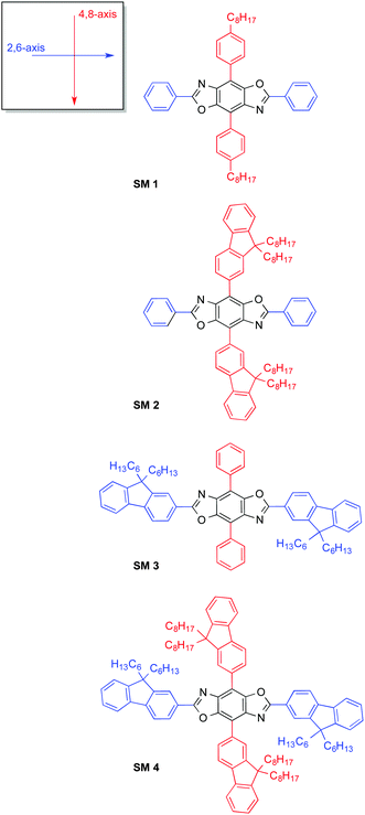
In this work we demonstrate, for the first time the utility of BBO cruciforms as a tunable platform for the development of organic semiconductors, Chart 1. Based on theoretical calculations, we synthesized four novel cross-conjugated molecules composed of the BBO core and different arrangements of phenyl- and fluorenyl-substitutents. We targeted the synthesis of deep blue light-emitting materials, as they are essential components in solid-state light based on white OLEDs.12 These wide band gap materials can also be used as hosts for green and red emitters to achieve the primary color required for displays.13 Unfortunately, the requisite wide band gap and corresponding reduction in emission quantum yield make it very challenging to attain efficient deep blue emission.13b,14 Thus we envisioned that a small molecule with tunable FMOs could best achieve these goals.
Results and discussion
Synthesis and characterization
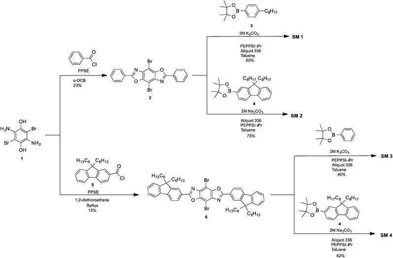
The synthetic approach for the 2,4,6,8-tetraarylBBOs is shown in Scheme 1. All of the molecules were prepared using a simple two step approach: a condensation reaction to prepare the 2,6-diaryl-4,8-dibromoBBOs and then a cross-coupling to extend conjugation across the central benzene ring. This approach allows for the synthesis of multiple BBOs from common intermediates. The condensation reaction of 3,6-diamino-2,5-dibromohydroquinone (1) with benzoyl chloride or 9,9-dihexyl-9H-fluorene-2-carbonyl chloride (5), afforded compounds 2 and 6 in yields of 23% and 15%, respectively. Although the yields for these steps were low, we were able to obtain adequate amounts of material for the next step. The cross-coupling of 2 with 4-octylphenylboronic acid (3) or 2-(9,9-dioctyl-9H-fluoren-2-yl)-4,4,5,5-tetramethyl-1,3,2-dioxaborolane (4) yielded SM 1 and SM 2 in yields of 60% and 75%, respectively. The cross coupling of 6 with phenylboronic acid or 4 afforded SM 3 and SM 4 in 40% and 62%, yield respectively. Purification of these compounds was easily accomplished by first passing through a short silica gel plug to remove non-polar and residual catalyst followed by precipitation from methanol. Lastly, the small molecules purified by a subsequent column and precipitation. The cruciforms were soluble in chlorinated solvents and characterized by NMR spectroscopy, and high-resolution mass spectrometry. The thermal properties of the materials were studied using differential scanning calorimetry (DSC) under nitrogen and thermogravimetric analysis (TGA) in air with a heating rate of 20 °C. All the BBOs showed excellent thermal stability under ambient conditions with 5% weight loss temperatures of 368, 357, 390 and 409 °C for SM 1, SM 2, SM 3 and SM 4 respectively (Fig. S2, ESI†). DSC did not reveal any transitions pertaining to melting or crystallization before the decomposition temperature. Thus, the heat generated during device operation should not alter the film morphology of these materials.Optical and electrochemical properties
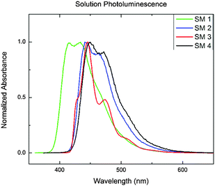
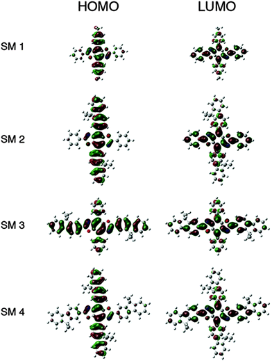
The solution UV-Vis absorption and photoluminescence spectra of the BBOs are shown in Fig. S4 (ESI†) and Fig. 1, respectively. The data is summarized in Table 1. All of the BBOs exhibited strong blue-emission in solution (433–450 nm). SM 1, SM 2 and SM 4 all had broad, featureless peaks, whereas SM 3 had a fairly shifted shoulder. The fluorescence quantum yields in solution as SM 1 was the lowest, SM 4 the highest and the constitutional isomers, SM 2 and SM 3 were identical. The electrochemical properties of the BBOs were investigated by cyclic voltammetry (CV) using a platinum working electrode in acetonitrile, with 0.1 M Bu4NPF6 as the electrolyte and an Ag/Ag+ reference electrode. The onsets were referenced to Fc/Fc+ and the results are summarized in Table 1. All of the materials exhibited measurable and reproducible oxidation and reduction processes. The HOMO values of the BBOs were similar,15 ranging from −6.0 to −6.2 eV, whereas the LUMO levels ranged from −2.7 to −3.7 eV. SM 1, with phenyl substituents in all four positions, had the deepest HOMO level (−6.2 eV), and the highest-lying LUMO level (−2.7 eV), resulting in the widest band gap. For the mixed systems possessing both fluorenyl and phenyl groups (SM 2 and SM 3) the band gaps were both 2.9 eV. Since both the phenyl and fluorenyl substitutents are weakly electron-donating the difference in the energy levels in these system is likely a result of the difference in conjugation length.10c This conclusion is verified by the band gap trend SM 1 > SM 2 = SM 3 > SM 4. The influence of substitutent selection, and location is further revealed in frontier orbital diagrams above (Fig. 2).| BBO | Abs λfilmmax (nm) | PL λfilmmax (nm) | Φ PL |
E
optg![[thin space (1/6-em)]](https://www.rsc.org/images/entities/char_2009.gif) a (eV) a (eV) |
HOMOb (eV) | LUMOc (eV) |
E
ECg![[thin space (1/6-em)]](https://www.rsc.org/images/entities/char_2009.gif) d (eV) d (eV) |
|---|---|---|---|---|---|---|---|
| a Estimated from the absorption onset of the film. b HOMO = −(Eoxonset + 4.8) eV. c LUMO = −(Eredonset + 4.8) eV. d E ECg = LUMO–HOMO. | |||||||
| SM 1 | 355 | 433 | 0.34 | 3.1 | −6.2 | −2.7 | 3.5 |
| SM 2 | 364 | 441 | 0.51 | 2.9 | −5.7 | −3.5 | 2.2 |
| SM 3 | 386 | 444 | 0.51 | 2.9 | −6.0 | −3.7 | 2.3 |
| SM 4 | 395 | 450 | 0.71 | 2.8 | −6.0 | −3.5 | 2.5 |
The electrochemical properties of the BBOs were investigated by cyclic voltammetry (CV) using a platinum working electrode in acetonitrile, with 0.1 M Bu4NPF6 as the electrolyte and an Ag/Ag+ reference electrode. The onsets for the BBOs ranged from 0.34–0.71. An increase in quantum yield was seen upon the addition of fluorene to the BBO core, narrow peak-width at half-max with a bathochromically-had.
Theoretical calculations
To further evaluate the structure–property relationships within these cross-conjugated BBOs, time-dependent density functional theory was performed. Initially, all four materials were optimized and their excited states generated using B3LYP/6-31G*. Based on previous benchmarking studies,16 it was determined that the MPW1PBE level with an SV basis set combined with the polarizable conductor calculation model (CPCM)17 mimicking the CHCl3 solvation effects provided the best correlation to experiment. Both sets of computational results were compared and contrasted to experimental CV and UV-Vis data and are summarized in Table 2 where the absolute HOMO and the band gap measurements was 0.2 eV leading to 3.5% and 6.9% errors, respectively. Conversely, the LUMO comparison suffered from much larger absolute and percent errors, which was expected based on the error in the CV as well as given the limitations inherent in DFT computations.15| BBO | HOMO (abs diff. from exp't) in eV | LUMO (abs diff. from exp't) in eV | E g (abs diff. from exp't) in eV | ||||||
|---|---|---|---|---|---|---|---|---|---|
| Exp't | B3LYP/6-31G* | MPW1PBE/SV-CHCl3 | Exp't | B3LYP/6-31G* | MPW1PBE/SV-CHCl3 | Exp't | B3LYP/6-31G* | MPW1PBE/SV-CHCl3 | |
| SM 1 | −6.2 | −5.3 (0.9) | −6.1 (0.1) | −2.7 | −1.9 (0.8) | −2.4 (0.3) | 3.1 | 3.2 (0.1) | 3.2 (0.1) |
| SM 2 | −5.7 | −5.2 (0.5) | −5.9 (0.2) | −3.5 | −1.9 (1.6) | −2.5 (1.0) | 2.9 | 2.9 (0.0) | 2.9 (0.0) |
| SM 3 | −6.0 | −5.3 (0.7) | −6.1 (0.1) | −3.7 | −2.0 (1.7) | −2.5 (1.2) | 2.9 | 3.0 (0.1) | 3.1 (0.2) |
| SM 4 | −6.0 | −5.1 (0.9) | −5.9 (0.1) | −3.5 | −2.0 (1.5) | −2.5 (1.0) | 2.8 | 2.8 (0.0) | 2.9 (0.1) |
The HOMO levels predicted by theory demonstrate the impact substituent identify plays along the 4,8-axis. Phenyl substituents (SM 1 and SM 3) lower the HOMO to −6.1 eV, whereas fluorenyl rings raise the HOMO to −5.9 eV (SM 2 and SM 4). The band gaps appear to be influenced by conjugation length as well as the extent of delocalization of electron density as shown in the frontier orbitals displayed in Fig. 3. There was localization along the donor axis for the HOMOs with the exception of SM 3. Both SM 2 and SM 4 demonstrated more localization along the acceptor axis than SM 3 or SM 1. These two trends along with conjugation length led to both lower band gaps and may play a part in the improved performance of SM 2 and SM 4 in OLEDs relative to SM 1 and SM 3. The importance of aryl ring identity was further examined by measuring the torsion angle produced between the 4,8-axis and the plane possessing the 2,6-axis, Fig. 3. The larger the torsion suppress the intermolecular aggregation between the BBO cores enhancing their efficiency in OLEDs.18 The ranking in order of increasing dihedral angle was: SM 4 < SM 2 < SM 1 < SM 3. As discussed below, SM 1 could not be fabricated into a working device with the CBP host material. SM 3 indicated unfavourable electron distribution in the frontier orbitals, thus SM 2 and SM 4, are the most viable candidates for use in OLEDs. Based on the torsion angle data, theory predicts that a SM 2 should produce better device than SM 4, and this is corroborated by the data below.
Organic light emitting diodes
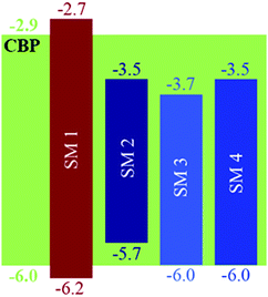
The EL of the cruciforms was evaluated in host–guest OLEDs using 4,4′-bis(9-carbazolyl)-biphenyl (CBP) as the small molecule host. The configuration for these devices was ITO/PEDOT:PSS(60 nm)/CBP:BBO/BPhen(40 nm)/LiF(1 nm)/Al(100 nm). The energy level diagrams and the EL spectra of devices comprising the CBP host and 10% of the guest (SM 1, SM 2 or SM 3) are shown in Fig. 4 and 5a, respectively. Due to the poor performance of the device from SM 1, the EL spectra could not be obtained. This result is not surprising as both the HOMO and LUMO levels for SM 1 are outside those for the CBP host. The emission maximum of SM 2 is red-shifted 11 nm from SM 3, demonstrating the influence of the direction of the extended conjugation axis. Similarly, the emission maximum of SM 4 was red-shifted 22 nm relative to SM 3 as a result of extended conjugation. The EL spectrum for SM 3 is similar in width and shape to its emission spectrum, but the peak widths at half-maximum for the EL spectra of SM 2 and SM 4 are considerably narrower than their emission spectra. The normalized electroluminescent spectra of devices with different weight% concentrations of the BBO's in the CBP host are shown below in Fig. 5. The key performance parameters of these OLEDs are summarized in Table 3. It can be seen from these plots that the host is quenched upon the addition of ∼5% of the guest molecule, indicating that there is efficient energy transfer from the host to the emitters. Interestingly, the best devices were obtained when 10 wt% of the guest was used. These results are also an improvement from our previous work where BBO polymer: CBP host systems were studied, as emission was not observed with 10% doping levels.19 This relatively high concentration of the guest suggests that excellent guest–host mixing is occurring in this system, as OLEDs based on neat films of the cruciforms exhibited strong concentration quenching. Such quenching is often a result of strong π-stacking within conjugated systems. Based on the optimized geometries in Fig. 3, we could surmise that SM 2, was the least planar and thus least susceptible to intermolecular aggregation. Indeed, SM 2, gave the best performance of all the molecules with an efficiency of ∼2 cd A−1 and a peak emission at 443 nm, when doped into the host at 10 wt%. The CIE 1931 coordinates for SM 2 of x = 0.16, y = 0.05, were well into the deep blue region. Interestingly, switching the conjugation axis had a detrimental impact on the OLED performance as SM 3 had the lowest efficiency, luminescence and EQE regardless of the doping level. This may be a result of the difference in the distribution of the electron density within the system as seen in the frontier orbitals, Fig. 3. Another contributing factor is that the deep HOMO level of SM 3 is close to that of the CBP guest. However, since SM 4 has the same HOMO level as SM 3 and performed significantly better, energy level misalignment is not likely the cause of the poor performance. In the future we will utilize a wider band gap host to further evaluate this phenomena. The device made using 2% of SM 4 gave the second best performance an efficiency of ∼1.9 cd A−1, with peak emission at 443 nm, and CIE 1931 coordinates x = 0.15, y = 0.09, which are close to the National Television System Committee (NTSC) blue color standard (0.14, 0.08).18,20 These are very promising materials considering that the photopic factor is only 0.023 at ∼445 nm. Furthermore, considering that the PL quantum yield is only 0.5, the maximum internal quantum efficiency is only ∼0.25 × 0.5 = 0.125 (yield of singlets times PL quantum yield), and the EQE is about ∼0.2 × 0.125 = 0.025 = 2.5%, since the outcoupling factor in these conventional bottom-emitting-through-the-glass OLEDs with ITO is <20%. Hence, based on the ΦPL of the emitting materials, the EQE of the deep blue fluorescent OLEDs based on SM 2 and SM 4 are close to the maximal possible values.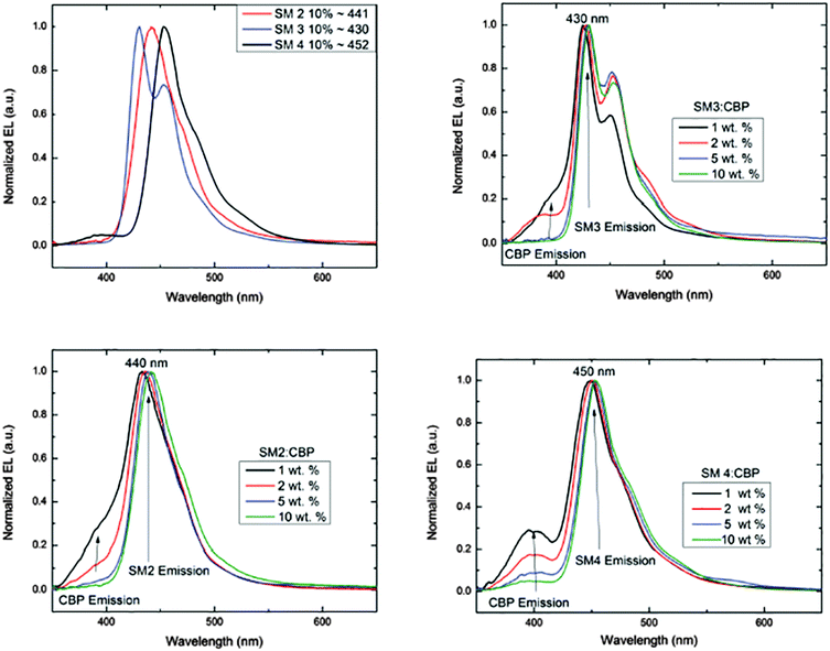 | ||
| Fig. 5 Electroluminescence spectra of SM 2–SM 4 (top left), and EL emission at various concentrations as noted. | ||
| Dopant | Device wt% | V on [V] | Drive voltage [V] | Current density J, [mA cm−2] | Brightness [cd m−2] | Efficiency [cd A−1, lm W−1 (% EQE)] | λ ELmax [nm] | CIE 1931 [x, y, y′] |
|---|---|---|---|---|---|---|---|---|
| SM 2 | 1.0 | 4.2 | 6.2 | 392 | 1155 | 0.93, 0.61, 1.82 | 433, 400 | 0.16, 0.05, 0.79 |
| 2.0 | 4.0 | 6.0 | 439 | 2152 | 1.30, 0.85, 2.33 | 436, 400 | 0.16, 0.05, 0.79 | |
| 5.0 | 4.4 | 6.6 | 489 | 1141 | 0.71, 0.45, 1.08 | 439, 400 | 0.16, 0.06, 0.78 | |
| 10.0 | 4.0 | 7.0 | 336 | 1051 | 2.05, 1.40, 2.95 | 443, 400 | 0.16, 0.05, 0.79 | |
| SM 3 | 1.0 | 5.0 | 8.0 | 365 | 275 | 0.33, 0.20, 0.60 | 425, 400 | 0.17, 0.06, 0.78 |
| 2.0 | 5.2 | 6.4 | 74 | 148 | 0.25, 0.13, 0.37 | 428, 400 | 0.16, 0.07, 0.77 | |
| 5.0 | 4.8 | 8.4 | 497 | 801 | 0.45, 0.25, 0.58 | 430, 400 | 0.17, 0.08, 0.76 | |
| 10.0 | 4.2 | 8.2 | 583 | 779 | 0.50, 0.33, 0.76 | 430, 400 | 0.16, 0.06, 0.78 | |
| SM 4 | 1.0 | 4.0 | 6.3 | 360 | 1649 | 1.23, 0.77, 1.55 | 450, 400 | 0.15, 0.09, 0.76 |
| 2.0 | 4.0 | 6.4 | 350 | 1568 | 1.93, 1.24, 2.22 | 450, 400 | 0.15, 0.09, 0.76 | |
| 5.0 | 3.9 | 6.4 | 404 | 1412 | 1.09, 0.67, 1.01 | 450, 400 | 0.16, 0.11, 0.73 | |
| 10.0 | 3.6 | 6.9 | 606 | 1159 | 1.29, 0.97, 1.20 | 450, 400 | 0.15, 0.11, 0.74 | |
Conclusions
In summary, we have synthesized four cross-conjugated, blue light emitting materials based on benzo[1,2-d:4,5-d′]bisoxazole. The HOMO and LUMO levels of these materials were readily tuned via substitution pattern to afford materials with wide-band gaps. Structure–property studies reveal that such modifications not only impact the energy levels and band gaps, but they also affect the electron density and planarity within the systems. As a result, the performance of the OLEDs varied depending upon structure. Non-optimized OLEDs achieved EQE approaching 3% and efficiency of ∼2 cd A−1 with a relatively narrow EL band peaking at 443 nm and a CIEy ≤ 0.05. Collectively these results indicate that the synthesis of BBO cruciforms is a promising strategy for the design of efficient deep-blue OLEDs. Future work is ongoing in our labs on OLED optimization and synthesis of new materials. These will be reported in due course.Experimental
Materials and measurements
Br-DAHQ (1),21 polyphosphoric acid, silyl ester (PPSE),22 were synthesized according to literature procedures. THF and toluene were dried using an Innovative Technologies solvent purification system. All other chemical reagents were purchased from commercial sources and used without further purification unless otherwise noted. Nuclear magnetic resonance (NMR) experiments were carried out in CDCl3 at 600 MHz (1H) AND 800 MHz (13C). In all spectra, chemical shifts are given in δ relative to tetramethylsilane. Coupling constants are reported in hertz (Hz). High-resolution mass spectra were recorded on a double-focusing magnetic sector mass spectrometer using ESI or APCI. Melting points were obtained on a melting point apparatus with 260 °C upper limit and are uncorrected. All UV-Vis and fluorescence spectroscopy were obtained using CHCl3 solutions unless otherwise noted. Relative solution fluorescence quantum yields were obtained using 9,10-diphenylanthracene (ΦPL = 0.885 in ethanol)23 as a standard with excitation at 372 nm.M.P. >260 °C, 1H NMR (400 MHz, CDCl3) 8.36 (2H, d, J = 4), 8.30 (2H, s), 7.86 (2H, d, J = 8), 7.79 (2H, dd, J = 4,4), 7.39 (6H, d, J = 4), 2.10 (9H, m), 1.06 (24H, m), 0.75 (12H, t), 0.60 (9H, m); HRMS (ESI) calcd for C58H66N2O2Br2 981.3564 [M + H]+, found 981.3559.
M.P. 242 °C, 1H NMR (600 MHz, CDCl3) δ 8.34–8.37 (8H, m, J = 6, 6 Hz), 7.54 (6H, d, J = 6 Hz), 7.47 (4H, d, J = 6 Hz), 2.75 (4H, m), 1.75 (4H, m) 1.55 (13H, s) 1.45 (5H, m), 1.38 (4H, m) 1.32 (10H, m) 0.90 (6H, t); 13C (400 MHz, CDCl3) δ 165.68, 152.10, 152.00, 147.37, 146.04, 140.35, 140.21, 128.91, 127.95, 127.53, 124.95, 123.50, 122.84, 121.61, 120.61, 91.86, 56.03, 40.83, 32.01, 30.12, 24.22, 23.03, 14.46; HRMS (ESI) calcd for C48H52N2O2 689.4102 [M + H]+, found 689.4087.
M.P. 149–152 °C, 1H NMR (800 MHz, CDCl3) δ 8.50 (2H, m, J = 8,8 Hz), 8.45 (2H, s), 8.37 (4H, dd, J = 8,8 Hz), 7.99 (2H, d, J = 8 Hz), 7.84 (4H, d, J = 8 Hz), 7.75 (2H, d, J = 8 Hz), 7.45 (2H, d, J = 8 Hz) 7.42 (2H, td, J = 8 Hz); 7.38 (2H, td, J = 8 Hz), 2.15 (10H,m), 1.17 (18H, m), 0.95 (4H, m), 0.82 (4H, m), 0.78 (14H, t, J = 8 Hz); 13C (800 MHz, CDCl3) δ 163.66, 151.51, 150.88, 146.62, 141.28, 141.05, 138.60, 131.61, 131.33, 129.29, 129.27, 129.01, 127.80, 127.50, 127.39, 127.00, 125.07, 125.05, 123.15, 120.16, 119.97, 114.99, 55.37, 40.82, 31.92, 31,90, 30.53, 29.54, 29.53, 29,46, 24.20, 22.73, 22.72, 14.19, 14.18 HRMS (ESI) calcd for C78H92N2O2 1089.7232 [M + H]+, found 1089.7228.
M.P. 214 °C, 1H NMR (600 MHz, CDCl3) δ 8.49 (2H, dd, J = 6 Hz), 8.44 (2H, s), 8.37 (4H, m), 7.98 (2H, d, J = 6 Hz), 7.82 (2H, d), 7.56 (6H, m), 6.14 (6H, m), 2.14 (9H, ddq), 1.13 (45H, dd), 0.76 (14H, t); 13C (800 MHz, CDCl3) δ 164.81, 151.88, 151.68, 146.74, 144.99, 140.37, 138.84, 133.03, 130.69, 130.67, 130.66, 129.01, 128.61, 128.44, 127.34, 127.29, 125.89, 123.30, 122.38, 120.31, 114.45, 55.72, 40.60, 31.85, 29.95, 24.07, 14.31; HRMS (ESI) calcd for C70H76N2O2 977.598 [M + H]+, found 977.5982.
M.P. 144–146 °C, 1H NMR (600 MHz, CDCl3) 1H NMR (600 MHz, CDCl3) 8.62 (2H, d, J = 6 Hz), 8.55 (2H, s), 8.32 (4H, m, J = 12 Hz), 7.99 (2H, d, J = 6 Hz), 7.81 (4H, t, J = 6 Hz), 7.73 (2H, dd), 7.40 (2H, d, J = 6 Hz) 7.33 (10H, m, J = 6,6 Hz); 13C (800 MHz, CDCl3) δ 164.44, 151.76, 151.53, 151.11, 146.87, 144.99, 141.48, 141.35, 140.45, 138.90, 131.83, 129.53, 129.50, 128.47, 127.56, 127.32, 127.15, 126.16, 125.05, 125.02, 123.37, 123.32, 122.22, 120.69, 120.34, 120.31, 120.18, 114.70, 55.81, 55.66, 41.13, 40.83, 32.11, 31.89, 30.76, 30.04, 29.70, 29.68, 24.39, 24.10, 22.90, 14.33,14.31; HRMS (ESI) calcd for C116H148N2O2 1602.1614 [M + H]+, found 1602.1583.
OLED fabrication and characterization
OLEDs were fabricated on nominally 10–20 ohms sq−1, 120–160 nm thick ITO-coated glass substrates (Colorado Concept Coatings). The substrates were first cleaned with a detergent and organic solvents and then treated in a UV/ozone oven to increase the work function of the ITO and hence facilitate hole injection, as described elsewhere. A 60 nm poly(3,4-ethylenedioxythiophene):polystyrene sulfonate (PEDOT:PSS) layer was spin-coated onto the ITO and then baked in air at 120 °C for 1 h and next in an argon-filled glove box at 120 °C for another 30 min. Blends of 4,4′-bis(9-carbazolyl)-biphenyl (CBP) and 1, 2, 5 and 10 wt% of SM 1–SM 4 in chlorobenzene solutions were spin-coated on top of the PEDOT:PSS layer in the argon-filled glovebox. The combined concentration of the CBP and guest material was kept constant at 9 mg mL−1. The solution was spin-coated at 4000 rpm for 60 s. The fabricated structure was then annealed at 60 °C for 30 min. Following this annealing step, the samples were transferred to a thermal evaporator within the glovebox, and the 4,7-diphenyl-1,10-phenanthroline (BPhen), LiF, and Al layers were deposited sequentially by thermal evaporation at a base pressure of ∼1 × 10⁻⁶ Torr. The OLEDs were characterized by monitoring their electroluminescence (EL) spectra and brightness as a function of the applied voltage, and the luminous and power efficiencies were determined.Computational details
All of the calculations on these oligomers studied in this work were studied using the Gaussian 03W with the GaussView 4 GUI interface program package. All electronic ground states geometries were optimized using density functional theory (DFT) employing an SVP functional and a 6-31G* basis set. Excited states were generated through time dependent density functional theory (TD-DFT) applied to the optimized ground state for each oligomer. The HOMO, LUMO, band gap, first ten excited states, and UV-Vis simulations were generated from these excited computations. All computations were performed using Gaussian 09 using the Marcy cluster provided by the MERCURY consortium.Acknowledgements
We would like to thank Dr Sarah Cady, Dr Kamel Harrata and Mr Steven Veysey of Iowa State University (ISU) Chemical Instrumentation Facility for compound analysis. We thank Eeshita Manna for technical assistance. We also thank the National Science Foundation (CHE-1413173) for financial support of this work. RK and JS were partially supported by Basic Energy Sciences, Division of Materials Science and Engineering, USDOE. Ames Laboratory is operated by Iowa State University for the US Department of Energy (USDOE) under Contract No. DE-AC 02-07CH11358. Computational resources were provided in part by the MERCURY consortium (http://mercuryconsortium.org/) under NSF grants CHE-0116435, CHE-0521063, CHE-0849677, and CHE-1229354.Notes and references
- G. Meller and T. Grasser, Organic Electronics, Springer, 2009 Search PubMed.
- T. A. Skotheim and J. R. Reynolds, Handb. Conduct. Polym., London, Boca Raton, Fla, 2007 Search PubMed.
- (a) D. Hu, J. Yu, K. Wong, B. Bagchl, P. J. Rossky and P. F. Barbara, Nature, 2000, 405, 1030 CrossRef CAS PubMed; (b) T. Huser, M. Yan and L. J. Rothberg, Proc. Natl. Acad. Sci. U. S. A., 2000, 97, 11187 CrossRef CAS PubMed.
- (a) R. E. Martin and F. Diederich, Angew. Chem., Int. Ed., 1999, 38, 1350 CrossRef; (b) S. Ellinger, K. R. Graham, P. Shi, R. T. Farley, T. T. Steckler, R. N. Brookins, P. Taranekar, J. Mei, L. A. Padilha, T. R. Ensley, H. Hu, S. Webster, D. J. Hagan, E. W. Van Stryland, K. S. Schanze and J. R. Reynolds, Chem. Mater., 2011, 23, 3805 CrossRef CAS; (c) S. S. Zade, N. Zamoshchik and M. Bendikov, Acc. Chem. Res., 2010, 44, 14 CrossRef PubMed; (d) R. E. Martin and F. Diederich, Angew. Chem., Int. Ed., 1999, 38, 1350 CrossRef.
- (a) Y. Sun, G. C. Welch, W. L. Leong, C. J. Takacs, G. C. Bazan and A. J. Heeger, Nat. Mater., 2012, 11, 44 CrossRef CAS PubMed; (b) O. Gidron, Y. Diskin-Posner and M. Bendikov, J. Am. Chem. Soc., 2010, 132, 2148 CrossRef CAS PubMed; (c) F. Zhang, D. Wu, Y. Xu and X. Feng, J. Mater. Chem., 2011, 21, 17590 RSC; (d) O. Gidron, A. Dadvand, Y. Sheynin, M. Bendikov and D. F. Perepichka, Chem. Commun., 2011, 47, 1976 RSC.
- (a) Q. Zhang, B. Kan, F. Liu, G. Long, X. Wan, X. Chen, Y. Zuo, W. Ni, H. Zhang, M. Li, Z. Hu, F. Huang, Y. Cao, Z. Liang, M. Zhang, T. P. Russell and Y. Chen, Nat. Photonics, 2015, 9, 35 CrossRef CAS; (b) X. Liu, Y. Sun, B. B. Y. Hsu, A. Lorbach, L. Qi, A. J. Heeger and G. C. Bazan, J. Am. Chem. Soc., 2014, 136, 5697 CrossRef CAS PubMed.
- C. J. Tonzola, A. P. Kulkarni, A. P. Gifford, W. Kaminsky and S. A. Jenekhe, Adv. Funct. Mater., 2007, 17, 863 CrossRef CAS.
- M. Cai, T. Xiao, E. Hellerich, Y. Chen, R. Shinar and J. Shinar, Adv. Mater., 2011, 23, 3590 CrossRef CAS PubMed.
- (a) J. N. Wilson, M. Josowicz, Y. Wang and U. H. F. Bunz, Chem. Commun., 2003, 2962 RSC; (b) A. J. Zucchero, P. L. McGrier and U. H. F. Bunz, Acc. Chem. Res., 2009, 43, 397 CrossRef PubMed; (c) P. L. McGrier, K. M. Solntsev, S. Miao, L. M. Tolbert, O. R. Miranda, V. M. Rotello and U. H. F. Bunz, Chem. – Eur. J., 2008, 14, 4503 CrossRef CAS PubMed; (d) J. A. Marsden, J. J. Miller, L. D. Shirtcliff and M. M. Haley, J. Am. Chem. Soc., 2005, 127, 2464 CrossRef CAS PubMed; (e) E. L. Spitler, L. D. Shirtcliff and M. M. Haley, J. Org. Chem., 2007, 72, 86 CrossRef CAS PubMed; (f) E. L. Spitler, J. M. Monson and M. M. Haley, J. Org. Chem., 2008, 73, 2211 CrossRef CAS PubMed; (g) K. Ohta, S. Yamada, K. Kamada, A. D. Slepkov, F. A. Hegmann, R. R. Tykwinski, L. D. Shirtcliff, M. M. Haley, P. Salek, F. Gel'mukhanov and H. Aagren, J. Phys. Chem. A, 2011, 115, 105 CrossRef CAS PubMed; (h) H. Kang, G. Evmenenko, P. Dutta, K. Clays, K. Song and T. J. Marks, J. Am. Chem. Soc., 2006, 128, 6194 CrossRef CAS PubMed.
- (a) J. E. Klare, G. S. Tulevski and C. Nuckolls, Langmuir, 2004, 20, 10068 CrossRef CAS PubMed; (b) J. E. Klare, G. S. Tulevski, K. Sugo, A. de Picciotto, K. A. White and C. Nuckolls, J. Am. Chem. Soc., 2003, 125, 6030 CrossRef CAS PubMed; (c) B. C. Tlach, A. L. Tomlinson, A. G. Ryno, D. D. Knoble, D. L. Drochner, K. J. Krager and M. Jeffries-El, J. Org. Chem., 2013, 78, 6570 CrossRef CAS PubMed; (d) K. Osowska and O. S. Miljanic, Chem. Commun., 2010, 46, 4276 RSC; (e) J. Lim, T. A. Albright, B. R. Martin and O. Š. Miljanić, J. Org. Chem., 2011, 76, 10207 CrossRef CAS PubMed; (f) M. A. Saeed, H. T. M. Le and O. Š. Miljanić, Acc. Chem. Res., 2014, 47, 2074 CrossRef CAS PubMed; (g) M. Jo, J. Lim and O. Š. Miljanić, Org. Lett., 2013, 15, 3518 CrossRef CAS PubMed; (h) J. Lim, D. Nam and O. S. Miljanic, Chem. Sci., 2012, 3, 559 RSC.
- (a) B. C. Tlach, A. L. Tomlinson, K. D. Morgan, C. R. Collins, M. D. Zenner and M. Jeffries-El, Aust. J. Chem., 2014, 67, 711 CrossRef CAS; (b) J. J. Intemann, E. S. Hellerich, B. C. Tlach, M. D. Ewan, C. A. Barnes, A. Bhuwalka, M. Cai, J. Shinar, R. Shinar and M. Jeffries-El, Macromolecules, 2012, 45, 6888 CrossRef CAS.
- (a) K. T. Kamtekar, A. P. Monkman and M. R. Bryce, Adv. Mater., 2010, 22, 572 CrossRef CAS PubMed; (b) G. Schwartz, S. Reineke, T. C. Rosenow, K. Walzer and K. Leo, Adv. Funct. Mater., 2009, 19, 1319 CrossRef CAS.
- (a) J. Chen, C. Shi, Q. Fu, F. Zhao, Y. Hu, Y. Feng and D. Ma, J. Mater. Chem., 2012, 22, 5164 RSC; (b) M. Zhu and C. Yang, Chem. Soc. Rev., 2013, 42, 4963 RSC.
- X. Yang, X. Xu and G. Zhou, J. Mater. Chem. C, 2015, 3, 913 RSC.
- C. M. Cardona, W. Li, A. E. Kaifer, D. Stockdale and G. C. Bazan, Adv. Mater., 2011, 23, 2367 CrossRef CAS PubMed.
- D. Wheeler and A. e. L. Tomlinson, unpublished results.
- (a) V. Barone and M. Cossi, J. Phys. Chem. A, 1998, 102, 1995 CrossRef CAS; (b) M. Cossi, N. Rega, G. Scalmani and V. Barone, J. Comput. Chem., 2003, 24, 669 CrossRef CAS PubMed.
- Y. Yu, Z. Wu, Z. Li, B. Jiao, L. Li, L. Ma, D. Wang, G. Zhou and X. Hou, J. Mater. Chem. C, 2013, 1, 8117 RSC.
- E. S. Hellerich, J. J. Intemann, M. Cai, R. Liu, M. D. Ewan, B. C. Tlach, M. Jeffries-EL, R. Shinar and J. Shinar, J. Mater. Chem. C, 2013, 1, 5191 RSC.
- S.-K. Kim, B. Yang, Y. Ma, J.-H. Lee and J.-W. Park, J. Mater. Chem., 2008, 18, 3376 RSC.
- B. C. Tlach, A. L. Tomlinson, A. Bhuwalka and M. Jeffries-El, J. Org. Chem., 2011, 76, 8670 CrossRef CAS PubMed.
- K. Yamamoto and H. Watanabe, Chem. Lett., 1982, 1225 CrossRef CAS.
- A. M. Brouwer, Pure Appl. Chem., 2011, 83, 2213–2228 CrossRef CAS.
Footnote |
| † Electronic supplementary information (ESI) available: 1H and 13C NMR spectra, cyclic voltammograms and details for the synthesis of intermediates. See DOI: 10.1039/c5tc03622d |
| This journal is © The Royal Society of Chemistry 2016 |

