
 Open Access Article
 This Open Access Article is licensed under a
 Creative Commons Attribution 3.0 Unported Licence
Screen-printed supercapacitors based on vitamin B2 functionalized carbon electrodes and deep eutectic solvent electrolytes
Chirag Mevada *a,
Aapo Kattainena,
Vijay Singh Parihar*b,
Amit Tewaria,
Jari Keskinena,
Minna Kellomäkib and
Matti Mäntysaloa
*a,
Aapo Kattainena,
Vijay Singh Parihar*b,
Amit Tewaria,
Jari Keskinena,
Minna Kellomäkib and
Matti Mäntysaloa
aFaculty of Information Technology and Communication Sciences, Tampere University, Tampere, Finland. E-mail: chirag.mevada@tuni.fi
bFaculty of Medicine and Health Technology, Tampere University, Tampere, Finland. E-mail: vijay.parihar@tuni.fi
First published on 25th November 2025
Abstract
As of 2025, 27 billion Internet of Things (IoT) devices require power, leading to the daily disposal of 80 million hazardous batteries. To address this, we aim to develop a low-cost printed supercapacitor (SC) to replace harmful batteries and reduce the environmental impact. We have developed an SC using a screen-printing technique with materials like cellulose diacetate (substrate), graphite ink (current collector), novel riboflavin functionalized activated carbon (electrode), green deep eutectic solvent (electrolyte), and cellulose (separator). The riboflavin (vitamin B2) functionalized activated carbon (RAC) electrode material was successfully synthesized using a solvothermal method. Comprehensive material characterization, including X-ray diffraction, Fourier transform infrared spectroscopy, thermogravimetric analysis, Raman spectroscopy, BET surface area analysis, X-ray photoelectron spectroscopy, and atomic force microscopy, confirmed the effective functionalization of riboflavin onto the activated carbon. Screen-printed SCs exhibit a specific capacitance of 20 F g−1 at a current density of 0.5 A g−1 and an operating voltage of 1.8 V. The device exhibits a specific energy of 7.6 W h kg−1 and a specific power of 1.6 kW kg−1, while maintaining 84% capacitance retention over 10![[thin space (1/6-em)]](https://www.rsc.org/images/entities/char_2009.gif) 000 charge–discharge cycles, comparable to commercial activated carbon (YP-80F). This work presents a promising pathway for developing flexible, soil-compatible, sustainable, and non-toxic SCs for IoT devices.
000 charge–discharge cycles, comparable to commercial activated carbon (YP-80F). This work presents a promising pathway for developing flexible, soil-compatible, sustainable, and non-toxic SCs for IoT devices.
1 Introduction
Supercapacitors (SCs), also referred to as electric double-layer capacitors, are utilized for energy storage in applications demanding either high-power output or an extended cycle life. These devices consist of two porous electrodes, current collectors, electrolyte, and a separator.1–4 Commercially available SCs use coconut shell derived activated carbon (AC) such as Kuraray YP 50F/80F and Cabot DLC SUPRA 30, as as electrode materials due to their relatively low cost and high specific surface area (>1500 m2 g−1).5,6 Ideally, charge builds up on the electrode surfaces through electrostatic interactions alone, without initiating electrochemical reactions – this feature supports the longer cycle life of SCs relative to conventional batteries. Electrode materials such as metal oxides and conducting polymers can generate additional pseudocapacitance by undergoing fast, reversible faradaic reactions. This results in increased capacitance, but often at the cost of stability and limited electrical conductivity, which can adversely affect the electrode's rate performance and cycling durability.7 Although significant efforts are underway to address these challenges by synthesizing composites consisting of carbon and pseudocapacitive materials through methods like doping, coating and incorporation of additives, the results have often fallen short of expectations.6 Also, it is important to highlight that the growing focus on sustainable energy technologies has encouraged recent developments in the exploration of eco-friendly electrode materials for SCs. Consequently, it is essential to develop eco-friendly electrode materials with outstanding rate performance and a straightforward approach to enhance its cycling stability.Recently, researchers have extensively utilized bio-based organic small molecules as active materials capable of undergoing redox reactions. The bio-sourced organic electrode demonstrates excellent performance when there is an adequate electron supply; however, these organic molecules often exhibit low conductivity. To address this challenge, conductive materials such as carbon nanotubes, graphene, carbon paper and activated carbon are integrated with these organic molecules to enhance their unique redox properties. For example, symmetrical SCs utilizing sepia melanin (derived from cuttlefish ink) and catechin/tannic acid on treated carbon paper have achieved capacitance values of 1355 mF cm−2 and 898 mF cm−2, respectively, at a scan rate of 5 mV s−1 in a 0.5 M Na2SO4 aqueous electrolyte, within a potential window of 1.6 V.8 Asymmetric SCs were developed by anchoring emodin molecules (a natural anthraquinone derivative and green organic pseudocapacitive material) onto graphene sheets, along with a caffeic acid-modified graphene hydrogel (E@GNS//GH-CFA). These devices exhibited a capacitance of 88 F g−1 at a scan rate of 10 mV s−1 in a 1 M H2SO4 electrolyte.9 A symmetrical SC fabricated using polydopamine nanofilm supported on oxygen-functionalized carbon cloth delivers a specific capacitance of 61 F g−1 at a current density of 1 A g−1.10 Carbon-based substrate materials are known for their excellent electrical conductivity and serve as effective conductive scaffolds during the redox reactions of organic small molecules, enhancing the electrochemical properties of these compounds. Nevertheless, most researchers tend to use carbon cloth and graphene as the carbon substrate, which can be costly and complex to produce. It is worth emphasizing that AC has emerged as a superior carbon matrix compared to carbon cloth, graphene sheets and carbon nanotubes due to its low cost and large specific surface area.11 Our recently published works showcase the successful grafting of dopamine and catechin bio-sourced organic molecules onto AC via the π–π stacking approach, resulting in specific capacitance values of 39 F g−1 and 37 F g−1, respectively, at a current density of 0.2 A g−1 for fully biocompatible 3D-printed symmetrical SCs.12,13
Recent research demonstrated the successful combination of riboflavin and AC composites through a straightforward adsorption method. The fabrication of the electrodes primarily involved drop casting a slurry of the composites, utilizing a fluorine-based binder and a nickel foam current collector.11 The aim of this investigation is to functionalize AC with vitamin B2, or riboflavin, commonly found in various vegetables, fruits, eggs, and dairy products using a π–π stacking approach for enhanced functionalization, rather than relying on simple adsorption. Additionally, we have employed printing techniques for electrode fabrication and utilize biobased materials for the substrate, current collector, binder, electrolytes, and separators. Printed electronics represent a major shift in SC manufacturing, offering a range of simple, cost-effective, and efficient fabrication techniques. These methods are flexible, environmentally friendly, and support the development of advanced SC designs, including micro, asymmetric, and flexible configurations, ultimately expanding SC applications in next-generation electronic devices.14,15 Recently, researchers have investigated different SC fabrication methods, including electroless plating, thermal evaporation, electrodeposition, and additive manufacturing. However, these techniques often involve intricate and expensive processes, posing challenges for large-scale production. Screen printing is a surface patterning technique that applies inks or gels onto a substrate through tiny openings in a mesh screen. This method shows considerable potential for the large-scale production of interdigitated SCs, owing to its cost-effectiveness, versatility with various substrates, variety of screen designs, and straightforward operational process. Moreover, screen printing allows for accurate control over both the thickness and geometry of the electrodes, making it suitable for printing on a wide range of flexible substrates, including paper, textiles, and plastics.16
In our recently published work, we successfully fabricated monolithic SCs through screen printing, employing AC as the electrode material and Texilac drying retardant to achieve screen-printability.17 The goal of this study is to remove Texilac from the ink formulation and incorporate bio-based pseudocapacitive materials to enhance the SC electrochemical performance. This study investigates the electrochemical properties of riboflavin-functionalized activated carbon (RAC) as an electrode material. Screen-printing techniques are utilized to create both the current collector and the electrode components. The electrochemical performance of RAC is compared to that of pristine activated carbon (PAC) electrodes through two-electrode systems in an aqueous electrolyte. Additionally, the research aims to develop an environmentally friendly screen-printed SC that incorporates cellulose diacetate (CDA) as the substrate, graphite ink as the current collector, RAC as the electrode, a deep eutectic solvent electrolyte, and cellulose as the separator. Deep eutectic solvents (DESs) are environmentally sustainable mixtures composed of quaternary ammonium salts and hydrogen bond donors combined in specific molar ratios to form eutectic systems. In the present study, the DES comprised choline chloride (ChCl) and urea in a molar ratio of 1:2, both of which are biodegradable, non-toxic, and readily available.18,19 In contrast, sodium chloride is non-biodegradable and adversely affects plants by impairing water absorption, which may lead to wilting even in moist soil. Elevated salt concentrations also disrupt the uptake of essential nutrients such as potassium, calcium, and magnesium. Prolonged exposure to salinity ultimately restricts plant growth and reduces crop yield as plants expend additional energy to mitigate salt-induced stress.20 These observations suggest that DES-based electrolytes contribute to improved biodegradability and reduced environmental impact compared with traditional salt-based electrolytes. By utilizing an eco-friendly DES, authors aim to mitigate these issues, supporting both plant health and sustainable agricultural practices. Finally, we conduct a comprehensive investigation into the electrochemical performance of the SC fabricated with screen-printed RAC electrodes and the choline chloride–urea based electrolyte. The developed devices are designed to power low-power wireless sensors for applications in the automobile sector, as well as agriculture and medical fields. Our goal is to bridge performance and sustainability, establishing a new paradigm in biodegradable energy storage and paving the way for the next generation of truly sustainable electronics.
2 Experimental section
2.1 Materials
Commercial activated carbon powder (YP-80F) was supplied by Kuraray Chemical Co., Japan. Optimont® CDA film (cellulose diacetate, 115 µm thick) was sourced from Bleher Folientechnik GmbH, Germany. Riboflavin, N,N-dimethylformamide (DMF, 99.5%), sodium chloride, choline chloride, urea, and chitosan (from shrimp shells, 50494) were obtained from Sigma-Aldrich. All chemicals were used as received, and Milli-Q grade deionized water (Millipore, Merck) was used for all experimental procedures.2.2 Synthesis of riboflavin functionalized activated carbon (RAC) particles
Riboflavin-functionalized activated carbon (RAC) was synthesized using a solvothermal approach. First, 10 g of PAC was dispersed in 60 mL of DMF at room temperature with an ultrasonic processor (UP200St, Hielscher Ultrasonics GmbH). Riboflavin was added to the uniform suspension in varying amounts of 1 g, 2 g, and 3 g, resulting in weight ratios of PAC to riboflavin of 10:1, 5:1, and 3.33:1, respectively. This dark, homogeneous mixture was transferred into a 125 mL autoclave (Model: 4748, Parr Instrument Company, USA) and heated at 180 °C for 12 hours. The resulting product was thoroughly washed with deionized water until a neutral pH was reached to eliminate any unbound RAC. Finally, the powder was dried in a hot air oven at 90 °C for 12 hours.
2.3 Synthesis of the deep eutectic solvent (DES)-based electrolyte
The DES electrolyte was prepared by mixing choline chloride salt and urea in a 1:2 molar ratio.18 The mixture was heated to 80 °C with continuous stirring (VMS C7 Advanced, VWR) until a clear, homogeneous liquid formed. Once cooled to room temperature, this liquid was utilized as the electrolyte for the SC.
2.4 Material characterization of PAC and RAC
X-ray diffraction (XRD) analysis of PAC, RAC and commercial riboflavin was conducted using a Panalytical Empyrean multipurpose diffractometer. The samples were placed on an amorphous holder and scanned in the 2θ range from 5° to 70° at a scanning rate of 2° per minute. The instrument utilized a Cu Kα radiation source (λ = 0.154 nm) with an operating voltage of 40 kV and a current of 40 mA. The functional groups and chemical bonds in samples were analyzed using a Fourier transform infrared (FTIR) spectrometer, PerkinElmer Spectrum One FTIR Spectrophotometer (PerkinElmer, Waltham, MA). Thermogravimetric analysis (TGA) of PAC, RAC, and commercial riboflavin materials was performed using a TGA-Q-500 instrument from TA Instruments (USA). This analysis was conducted over a temperature range of 30 to 790 °C in a nitrogen (N2) atmosphere. Raman spectra for PAC and RAC were recorded with a Renishaw inVia Qontor Raman spectrometer, which was connected to a confocal microscope with a 50× objective lens. A diode-pumped solid-state laser with a 532 nm excitation line and 30 mW power was used. Each spectrum was averaged over 10 acquisitions of 40 seconds each, spanning from 100 to 2500 cm−1. The Brunauer–Emmett–Teller (BET) specific surface area and pore size distribution of samples were measured from the N2 adsorption–desorption curve at 77 K using a Micromeritics 3Flex adsorption analyzer (Micromeritics Instrument Corporation, US). X-ray photoelectron spectroscopy (XPS) measurements were conducted under ultra-high vacuum conditions using an ESCA Model 3000 instrument from Omicron Nanotechnology GmbH. The base pressure during these measurements was carefully kept below 1 × 10⁻¹⁰ mbar. For XPS excitation, we used a focused, monochromatized Al Kα radiation source (hν = 1486.5 eV). Data acquisition, processing, and analysis were carried out with CasaXPS version 2.3.22 PR1.0. After subtracting the Shirley background, peak fitting was performed using a symmetrical Gaussian–Lorentzian function, with the line shapes of the fitted components approximated by a 50% Gaussian and 50% Lorentzian mix. Atomic force microscopy (AFM) images were obtained using a Bruker Dimension Icon AFM system in tapping mode with intermittent contact. Screen-printed PAC and RAC samples on PET (125 µm thick Melinex ST506 film, TEKRA LLC, US) substrates were used. The setup included the ScanAsyst in Air model, operating at a resonant frequency of 1 kHz and a force constant of 0.72 N m−1. The cantilever dimensions were 650 nm for the tip, 115 µm in length, and 25 µm in width.2.5 Fabrication of screen-printed symmetric supercapacitors
Symmetric SCs for aqueous electrolytes were constructed on commercially available aluminum-laminated polyethylene terephthalate (PET) film provided by Pyroll (with Al/PET thicknesses of 9 µm/50 µm, respectively). The PET side of the film was used for screen-printing current collectors and electrodes, while the aluminum layer served as an outer barrier against electrolyte evaporation. For SCs, a cellulose diacetate substrate was used. Printing was conducted using an EKRA X5 Professional sheet-to-sheet screen printer, with parameters listed in Table 1. Rectangular current collectors (34 mm × 31 mm) with an approximate dry thickness of 21.8 ± 0.7 µm were first printed using commercial graphite ink (LOCTITE EDAG PF 407C E&C) and cured at 95 °C for 1 hour. Electrodes (PAC and RAC) measuring 33 mm × 10 mm were printed on top of the cured collectors and subsequently cured in an oven at 60 °C for 30 minutes, yielding average dry masses of 8.2 mg for PAC and 6.3 mg for RAC from both electrodes. A digital micrometer (Mitutoyo ABSOLUTE Digimatic Indicator, Mitutoyo Corp., Japan) was used to evaluate the thickness and uniformity of the printed electrode and current collector layers. Dry thickness was recorded from nine points across each printed surface and assumed to be normally distributed around the measured sample mean to obtain the estimated layer thickness distributions as shown in Fig. S1. A similar analysis was performed for the Optimont® CDA film (cellulose diacetate, 115 µm thick) substrate, which demonstrated an average thickness of 115 µm with a standard deviation of 0.4 µm. Due to the high thread diameter of the current collector screen, the printed graphite layer demonstrated a relatively high average thickness of 21.8 µm, while PAC and RAC demonstrated slightly lower average thicknesses of 13.1 µm and 15.7 µm, respectively. Since the uniformity of each layer is affected by the surface roughness of the layers below it, the standard deviation can be observed to slightly increase with each added layer; however, all printed layers exhibit decent uniformity and high deposition thickness, allowing high-mass-loading electrode and current collector fabrication. The electrolyte was applied to the cured electrodes with a micropipette, and a paper separator (Dynacap GT 0.45/40 from Glatfelter Gernsbach GmbH) was placed between electrodes to prevent short-circuiting. SCs were loaded with aqueous NaCl electrolyte (NaCl:H2O at a 1:5 mass ratio) and DES electrolyte. Due to the DES's high viscosity, it was allowed to soak into the electrodes overnight to thoroughly saturate the porous structure. Finally, the SCs were assembled by aligning the electrodes and sealing them with adhesive tape (3M 468 MP). A schematic illustration of the screen-printed SCs is shown in Fig. 1. Specifically, the device measures 5 cm × 5 cm with a thickness of approximately 340 µm.
| Current collectors | Electrodes | |
|---|---|---|
| Mesh parameters | ||
| Mesh count (cm−1) | 24 | 48 |
| Thread diameter (µm) | 125 | 55 |
|
||
| Printing parameters | ||
| Printing speed (mm s−1) | 20 | 20 |
| Squeegee force (N) | 200 | 200 |
| Snap-off (mm) | 2.00 | 1.50 |
 | ||
| Fig. 1 Schematic illustration of the SC fabrication process and device dimensions, showing (I) screen printing of the current collectors and electrodes, (II) device dimensions, and (III) the assembled device, as indicated in the figure. | ||
2.6 Electrochemical characterization
To identify pseudocapacitance peaks in RAC and PAC electrodes, a CV test was recorded using the three-electrode measurements. All measurements were performed using a Zahner electrochemical workstation (Zahner-elektrik GmbH & Co. KG, Germany) from the Zennium series, operated through the Thales software package. For the comparative analysis of RAC (1.5 mg) and PAC (1.7 mg) electrodes, 6 M KOH was utilized as the electrolyte, while a Hg/HgO electrode functioned as the reference electrode. A platinum wire (99.9% purity, 0.6 mm in diameter, 250 mm in total length-comprising a 215 mm helix and a 35 mm straight section) served as the counter electrode. The electrochemical measurements were performed within a voltage window of −1.0 V to 0 V for 6 M KOH and 0 V to 1.0 V for NaCl electrolyte. All experiments were carried out in a 50 mL BEC (Basic Electrochemical Cell) (redoxme AB, Sweden).Moreover, to evaluate the faradaic contributions and charge storage role of riboflavin, the electrochemical performance of PAC- and RAC-based devices was tested using a Zahner electrochemical workstation, building on prior electrode material assessments. CV curves were recorded at lower scan rates (1, 2, 5, 8, and 10 mV s−1) in an aqueous NaCl solution with a NaCl-to-water mass ratio of 1:5, within a potential range of 0 to 1.2 V. The active material mass loading for SCs was around 9 ± 0.2 mg for PAC and 6.0 ± 0.2 mg for RAC on both electrodes. Specific capacitance for PAC and RAC devices was calculated from the fifth CV cycle, applying eqn (1).8,21–23
 | (1) |
dV corresponds to the integrated area under the CV curve, ν denotes the scan rate in mV s−1, m is the total mass of the active material in g, and ΔV is the potential range in V.
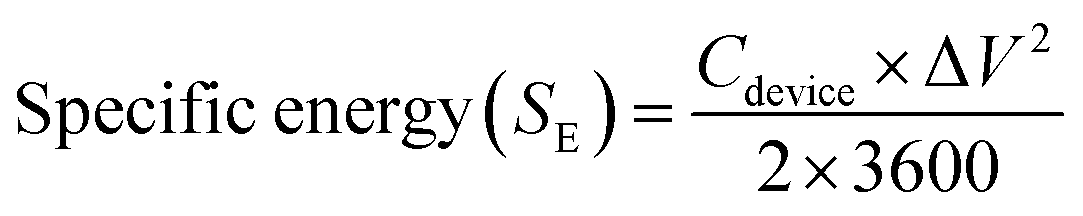
Galvanostatic charge–discharge (GCD) measurements for devices in a two-electrode setup were conducted using a Maccor 4300 instrument (Maccor, Inc., USA). The total mass loading for DES-based devices across both electrodes was approximately 7 mg. The CV scans were conducted within a potential range of 0 to 1.8 V at scan rates of 5, 10, 50, and 100 mV s−1, while GCD measurements were carried out at current densities of 0.15, 0.5, and 1.5 A g−1. The GCD data were analyzed to determine equivalent series resistance (ESR) and specific capacitance values using eqn (2) and (3).24 Specific energy (W h kg−1) and specific power (W kg−1) for DFAC-based SCs were calculated from the GCD data using eqn (4) and (5).25
 | (2) |
 | (3) |
 | (4) |
 | (5) |
3 Results and discussion
3.1 Material characterization of PAC and RAC
To gain deeper insight into the functionalization of riboflavin with PAC, this study incorporated various spectroscopic analyses and BET specific surface area measurements. Fig. 2a illustrates the XRD patterns of commercial riboflavin, RAC, and PAC. A significant rise in intensity around the 2θ value of about 10° in the XRD pattern of PAC and RAC indicates a high density of pores. This feature points to a well-developed porous structure, characteristic of materials with large surface areas and intricate pore networks.11,26,27 When comparing the XRD patterns of PAC and RAC, a noticeable increase in the intensity of the diffraction peaks at 2θ values around 23.9°and 43.9° is observed for RAC. This increase in peak intensity is due to the adsorption of riboflavin molecules onto the PAC surface, facilitated by the aromatic ring structures within riboflavin.11 Specifically, the diffraction peak observed at 10.8° in RAC matches that of commercial riboflavin and is not seen in PAC samples, further confirming the presence of riboflavin on PAC. The XRD analysis results confirm the functionalization of riboflavin on the surface of PAC. The FTIR spectra of commercial riboflavin, RAC, and PAC are presented in Fig. 2b. Commercial riboflavin exhibits distinct peaks corresponding to its functional groups: a broad O–H stretching peak around 3200–3600 cm−1, indicating hydroxyl groups; N–H stretching peaks between 3100 and 3400 cm−1, associated with amine groups; and strong –C![[double bond, length as m-dash]](https://www.rsc.org/images/entities/char_e001.gif) O stretching peaks near 1650–1750 cm−1, characteristic of the carbonyl groups in the isoalloxazine ring. Peaks from C–N and CC vibrations within 1400–1600 cm−1 represent aromatic and heterocyclic structures, and C–H stretching peaks around 2800–3000 cm−1 are indicative of both aliphatic and aromatic C–H bonds. The FT-IR spectrum of RAC prominently displays peaks in the 1400–1800 cm−1 region, corresponding to riboflavin's functional groups.28 In contrast, these peaks are absent in PAC, confirming successful π–π stacking interactions between riboflavin and PAC. TGA was conducted to evaluate the thermal stability of RAC and to confirm the functionalization of riboflavin on activated carbon by examining its impact on the thermal degradation profile. All samples were heated from 30 °C to 800 °C to record their weight loss profiles across the temperature range. TGA was conducted under a 40:60 nitrogen–air atmosphere to control oxidation and prevent rapid or complete combustion. The weight loss curves, as shown in Fig. 2c, provided significant insights into the thermal behavior of the materials. For commercial riboflavin, the thermograms displayed a multi-step degradation process across a wide temperature range. Initially, the evaporation of physically adsorbed water occurred at temperatures below 100 °C. This was followed by three distinct degradation events, including a peak between 230 and 300 °C, another sharp peak from 280–300 °C, and a prominent degradation peak within 480–510 °C. An additional degradation phase was also observed in the range of 650–680 °C. In comparison, the thermal degradation profile of RAC showed significant changes compared to PAC. For RAC, a two-step degradation pattern was evident in the temperature range of 150–550 °C, followed by a secondary degradation phase extending from 650–680 °C. Meanwhile, PAC exhibited a single degradation peak between 650 and 700 °C. Furthermore, the difference in residual weight at 650 °C indicated that approximately 18–20 wt% of riboflavin had been successfully functionalized onto the PAC.
O stretching peaks near 1650–1750 cm−1, characteristic of the carbonyl groups in the isoalloxazine ring. Peaks from C–N and CC vibrations within 1400–1600 cm−1 represent aromatic and heterocyclic structures, and C–H stretching peaks around 2800–3000 cm−1 are indicative of both aliphatic and aromatic C–H bonds. The FT-IR spectrum of RAC prominently displays peaks in the 1400–1800 cm−1 region, corresponding to riboflavin's functional groups.28 In contrast, these peaks are absent in PAC, confirming successful π–π stacking interactions between riboflavin and PAC. TGA was conducted to evaluate the thermal stability of RAC and to confirm the functionalization of riboflavin on activated carbon by examining its impact on the thermal degradation profile. All samples were heated from 30 °C to 800 °C to record their weight loss profiles across the temperature range. TGA was conducted under a 40:60 nitrogen–air atmosphere to control oxidation and prevent rapid or complete combustion. The weight loss curves, as shown in Fig. 2c, provided significant insights into the thermal behavior of the materials. For commercial riboflavin, the thermograms displayed a multi-step degradation process across a wide temperature range. Initially, the evaporation of physically adsorbed water occurred at temperatures below 100 °C. This was followed by three distinct degradation events, including a peak between 230 and 300 °C, another sharp peak from 280–300 °C, and a prominent degradation peak within 480–510 °C. An additional degradation phase was also observed in the range of 650–680 °C. In comparison, the thermal degradation profile of RAC showed significant changes compared to PAC. For RAC, a two-step degradation pattern was evident in the temperature range of 150–550 °C, followed by a secondary degradation phase extending from 650–680 °C. Meanwhile, PAC exhibited a single degradation peak between 650 and 700 °C. Furthermore, the difference in residual weight at 650 °C indicated that approximately 18–20 wt% of riboflavin had been successfully functionalized onto the PAC.
 | ||
| Fig. 2 (a) XRD patterns, (b) FTIR spectra, and (c) TGA curves for PAC, RAC, and commercial riboflavin (performed from 30 °C to 800 °C under a 40:60 nitrogen–air atmosphere); (d) Raman spectra, (e) nitrogen adsorption–desorption isotherms, and (f) BJH pore-size distribution curves for PAC and RAC. | ||
Fig. 2d reveals the presence of two distinct peaks at 1340 cm−1 and 1600 cm−1, corresponding to the D-band and G-band, respectively. The data indicate minimal variation in the ID/IG ratio, suggesting only small changes in the structural disorder and graphitic nature of the material. For instance, the ratio for PAC and RAC turns out to be 1.17 and 1.15, respectively. The results obtained align with the trends observed by Lv et al. (2023) for riboflavin-functionalized activated carbon.11 In case of PAC, the high value of this ratio (1.17) suggests more structural disorder due to the presence of numerous defects sites at the edges of these flakes.29 On the other hand, the addition of riboflavin into the matrix of PAC functionalizes the parent material, which thus participates in cross bonding formation with the unbonded carbon atoms available at the edges. This leads to reduction in the existing disordered nature in the activated carbon structure, finally creating a more stable, ordered and conjugated structure. Nitrogen adsorption–desorption isotherm curves were employed to assess the specific surface area and pore distribution of PAC and RAC. As shown in Fig. 2e, both samples exhibit nitrogen adsorption curves typical of type IV isotherms, with a distinct hysteresis loop observed between P/P0 = 0.45 and 1. This suggests that mesoporous structures predominate in both samples (as displayed in Fig. 2f).26 The specific surface areas of PAC and RAC are 2240 and 1600 m2 g−1, respectively, with an average adsorption–desorption pore diameter of 2.5 nm. Furthermore, the total pore volume for pores smaller than 40 nm at P/P0 = 0.95 was 1.352893 cm3 g−1 for PAC and 1.015926 cm3 g−1 for RAC. The functionalization of riboflavin significantly modified the pore structure of PAC. Moreover, the adsorption of riboflavin led to a reduction in the size of various pores, collectively contributing to a decrease in both pore volume and specific surface area. These findings are consistent with previous studies that reported a significant decrease in the specific surface area of PAC after the introduction of riboflavin.11 For instance, prior research noted a reduction in the specific surface area of carbon from 2301 m2 g−1 to 1681 m2 g−1 upon modification of activated carbon with riboflavin. The work reported by Tisawat et al. (2019) also noted similar effects when grafting various quinones onto activated carbon derived from coconut shells.30 In conclusion, riboflavin molecules effectively integrate with PAC, predominantly adsorbing within the internal pores rather than on the outer surface. This distribution explains the insolubility of riboflavin in both aqueous and DES electrolytes.
The elemental analysis of PAC and RAC was performed using XPS. Fig. 3b–h represents the wide scan and deconvoluted core level of different elements (C1s, N1s and O1s) in both these samples. The presence of nitrogen (N1s) in the riboflavin sample has been confirmed in Fig. 3d along with carbon (C1s) and oxygen (O1s) in its survey scan unlike the PAC sample. The carbon (C) peak comprises four deconvoluted components at 284.8 eV, 285.95 eV, 286.94 eV and 289.48 eV associated with sp2 hybridized carbon, C–O, CO, and OC–O, respectively, in PAC samples; however, one of the components (out of the four mentioned above) at 287.5 eV has been substituted by N–CO in riboflavin as established by its chemical structure.11,31,32 Moreover, the presence of nitrogen in N1s (Fig. 3d) at 399.4 eV in the riboflavin sample only confirms this claim. Further, the high-resolution components of O1s in the PAC sample include three components at 533.4 eV, 534.3 eV, and 535.2 eV corresponding to (CO/O–CO), C–O, and –COOH (very small amount less than 1 at wt%) whereas a shift of approximately 1 eV towards lower binding energy has been observed in all the above peaks in case of riboflavin. This can be attributed to the chemical environment and bonding of oxygen atoms in riboflavin (say N–CO at 532 eV in Fig. 3c),11 due to the more complex chemical structure of riboflavin as compared to PAC, which includes a change in the chemical environment of the carbon atom bonded with nitrogen and oxygen. The quantitative analysis (atomic percentage, at%) of the deconvoluted XPS peaks for the different components in the PAC and RAC samples has been provided in the SI as Tables S1 and S2. The above XPS results further confirm the functionalization of riboflavin with PAC, consistent with the findings from XRD, FTIR, Raman, TGA, and BET characterization.
 | ||
| Fig. 3 XPS spectra of RAC: (a) survey scan, (b) C 1s, (c) O 1s, and (d) N 1s; and XPS spectra of PAC: (e) survey scan, (f) C 1s, (g) O 1s, and (h) N 1s. | ||
It is important to note that the PAC and RAC samples exhibited rough surfaces, making it difficult to obtain clear EDS maps and perform effective FESEM and TEM analysis. Drawing from our previous experience with catechin-grafted PAC13 and dopamine-functionalized PAC,12 we encountered similar challenges. Consequently, to examine the surface morphologies of the PAC and RAC samples, we employed AFM analysis. This method was chosen for its ability to deliver highly reliable results under the specified conditions. The findings from this analysis are presented in Fig. 4, showcasing the detailed topographical features of the samples. The average roughness (Ra) and the root mean square roughness (Rq) of these surfaces are summarized in Table 2 and provide insight into the topographies of their surfaces after screen-printing. It has been observed that both the roughness values, i.e. the average and root mean square (RMS) roughness of films, show a decremental trend upon addition of riboflavin into PAC. This can be attributed to the surface modification done by the riboflavin molecules that participate in the chemical interaction with PAC molecules exhibiting the neutralization of pores and irregularities in the films, resulting in masking the underlying roughness. Moreover, it can be speculated that the impact of smooth films can clearly be seen in Fig. 6f where the contribution to the diffusion capacitance due to riboflavin pseudocapacitance is prominent as compared with EDLC. Thus, RAC can improve the uniformity of the film and thus enhance the figure-of-merit of the devices.
 | ||
| Fig. 4 Atomic force microscopy planar view (left column) and 3D view (right column) images of screen-printed samples of (a) PAC and (b) RAC in the 3 µm × 3 µm region, respectively. | ||
| Samples | Average roughness (Ra) | RMS roughness (Rq) |
|---|---|---|
| PAC | 274 nm | 222 nm |
| RAC | 246 nm | 188 nm |
We performed rheological measurements to examine the shear-thinning characteristics and gel-like elastic properties of both inks. All measurements were carried out at room temperature using a rotational rheometer (DHR-2, TA Instruments Inc., USA) equipped with a 20 mm parallel plate geometry. The apparent viscosity was measured across a shear rate range of 0.1–500 s−1 to analyze the flow characteristics, while oscillatory tests were performed over a frequency range of 1–100 rad s−1 to determine the storage (G′) and loss (G″) moduli. The corresponding results are presented in Fig. S2. The prepared RAC and PAC with Texilac inks demonstrate shear-thinning and non-Newtonian fluid behavior, characterized by a decrease in viscosity with increasing shear rate (Fig. S2a). This property is crucial for ensuring smooth and continuous flow during the printing process. The viscosity values of the RAC and PAC inks containing Texilac were measured to be 340 Pa s and 549 Pa s, respectively, at an initial shear rate of 0.1 s−1. These high viscosities suggest that the inks can pass through the screen mesh effectively when subjected to applied pressure.33 The storage modulus (G′) exceeds the loss modulus (G″) throughout the oscillation frequency range of 1–100 rad s−1, indicating the characteristic gel-like elastic behavior of the material (Fig. S2b). The rheological characteristics of the RAC and PAC with Texilac inks confirm their excellent printability, enabling the formation of precise fine patterns without distortion.
3.2 Electrochemical performance of PAC and RAC screen-printed SCs in aqueous electrolyte
Electrochemical studies were conducted using PAC to riboflavin weight ratios of 10:1, 5:1, and 3.33:1 to optimize the amount of riboflavin functionalization in PAC. Devices were fabricated through screen printing, and their electrochemical performance was evaluated. Fig. 5a–c displays the GCD curves for each PAC-to-riboflavin ratio at various current densities. Among the devices tested, the 5:1 PAC-to-riboflavin weight ratio exhibited the highest storage capacity under all conditions. Therefore, this ratio was selected for further investigation, where its electrochemical properties were compared to those of PAC-based devices. Riboflavin is a well-known electroactive material, exhibiting a redox potential between −0.9 and −0.65 V (vs. Hg/HgO) in alkaline solution.11 In this study, we used 6 M KOH as the electrolyte and Hg/HgO as the reference electrode. CV measurements were performed at different scan rates (2 to 100 mV s−1) for both electrodes, and the resulting curves are presented in Fig. 5f and g. As displayed in Fig. 5d and e, compared to the CV curve of PAC, the CV curves of RAC display an additional pair of well-defined redox peaks in the −0.65 V to −0.9 V range (vs. Hg/HgO), confirming that riboflavin undergoes redox transitions within this potential window under the specified experimental conditions. The minimal peak separation and high symmetry indicate a highly reversible redox process. This enhanced electrochemical reversibility enables efficient charge storage at high current densities, thereby improving the rate capability of the RAC electrode. The CV curves recorded at varying scan rates for the RAC electrode, as shown in Fig. 5f, reveal a linear increase in pseudocapacitive peak current with applied voltage as the scan rate increases from 2 mV s−1 to 100 mV s−1. This behavior indicates a fast surface-controlled faradaic reaction in the RAC electrode. However, at scan rates exceeding 50 mV s−1, distortion in the CV curves becomes evident, likely due to insufficient time for solvated ions to reach active sites, resulting in a characteristic leaf-shaped CV profile. For the PAC electrode, the current response increases proportionally with scan rate, and the CV curves maintain a quasi-rectangular shape, characteristic of electric double-layer capacitance behavior (Fig. 5g). We also employed the Trasatti method to distinguish between faradaic and non-faradaic contributions to the overall charge storage in PAC and RAC electrode-based devices.4,23,34
 | ||
| Fig. 5 Comparison of GCD curves recorded for PAC to riboflavin weight ratios of 10:1, 5:1 and 3.33:1: (a) 0.15 A g−1, (b) 0.5 A g−1, and (c) 1.5 A g−1 for devices, CV curve recorded at (d) 10 mV s−1, (e) 20 mV s−1, and (f) various scan rates for the RAC electrode, (g) different scan rates for the PAC electrode, dependence of (h) Cs vs. ν−0.5 and (i) 1/Cs vs. ν0.5 for PAC and RAC electrodes. | ||
CV curves at low scan rates (ν ≤ 10 mV s−1) were recorded for PAC and RAC based electrodes and the specific capacitance was calculated using eqn (1). When assuming a semi-infinite linear diffusion pattern (ν → +∞), we assessed the maximum CEDLC (Fig. 5h) by plotting the linear relation between the calculated specific capacitances (Cs) vs. the reciprocal of the square root of scan rate (ν−(0.5)) using the following equation (eqn (6)).
 | (6) |
| CT = CEDLC + CPSEUDO | (7) |
 | (8) |
The percentage of each capacitance contribution can be evaluated as follows:
 | (9) |
 | (10) |
As anticipated, PAC primarily stores charge through capacitive processes, confirming its dominant EDLC behavior. However, the functionalization of riboflavin on PAC alters the charge storage mechanism, shifting it toward a diffusion-controlled process. This suggests that in the RAC electrode, charge storage occurs predominantly via ion intercalation and de-intercalation within the electrode structure. The findings reveal that pseudocapacitance contributes approximately 61% to the total charge storage in the RAC based electrode, primarily due to riboflavin. In contrast, PAC based electrode devices exhibit a pseudocapacitance contribution of about 28% (Fig. S3), which can be attributed to the presence of functional groups such as hydroxyl groups (C–O), carbonyl groups (CO) and carboxyl groups (COOH). These groups take part in redox reactions in the electrolyte, contributing to pseudocapacitive charge storage along with normal electrostatic capacitance. Furthermore, the XPS reported by Karamanova et al. (2020) confirmed the presence of these functional groups on the YP-80F surface.35 The material is produced using a physical or chemical activation process with steam or CO2 at high temperature, which creates micropores and exposes carbon edges, forming active sites where oxygen and other elements can bond. These oxygen-functionalized sites help create redox-active centers, improving the energy storage capacity of YP-80. Screen-printed symmetric devices based on PAC and RAC electrodes were fabricated. Comparison curves of CV and GCD of PAC and RAC devices under the same test conditions are presented in Fig. 6a and b. The results obtained showed that the larger CV integral area and longer charge/discharge time for RAC devices indicate superior electrochemical properties compared to PAC devices. Specifically, RAC devices exhibit a specific capacitance of 28.6 F g−1 at 0.5 A g−1, far exceeding that of PAC SCs (10.8 F g−1) at the same current density. Fig. 6c presents the GCD curves recorded at various current densities. Trasatti analysis was also applied to PAC- and RAC-based devices, with the results plotted in Fig. 6d and e to quantify the contributions from electric double-layer capacitance (CEDLC) and total capacitance (CT) using the equations outlined in previous sections. The capacitive and diffusive contributions extracted from these analyses are summarized in Fig. 6f. The findings demonstrate consistency between three-electrode and two-electrode measurements. Notably, RAC-based devices exhibited a 33% higher diffusive contribution, attributed to the pseudocapacitive nature of riboflavin. Furthermore, a plausible explanation for this improvement in electrochemical properties is that riboflavin contains several functional groups, such as hydroxyl (–OH), methyl (–CH3), and ketone (CO) groups. The incorporation of hydroxyl (–OH), methyl (–CH3), and ketone (CO) groups in chitosan-based binders and activated carbon inks can significantly enhance printing performance in several ways.36–38 Hydroxyl groups significantly boost the hydrophilicity of PAC, enhancing its dispersion in aqueous solvents and binders. This results in a more uniform and stable ink formulation. On the other hand, methyl groups improve compatibility with printing media and enhance the ink's flow properties. They also adjust the surface energy of PAC, making it ideal for specific printing applications that require controlled interaction with the medium. Meanwhile, ketone groups increase the surface energy of PAC, improving its wettability and dispersion within the printing medium. Additionally, these ketone groups can engage in chemical interactions with the components of the printing medium, further enhancing the ink's stability and performance. This improvement makes them printable without the use of Texilac drying retarder (EPTAINKS Texilac Ritardante M167380L001000). These results indicate the successful fabrication of the RAC composite and highlight the effect of riboflavin on improving charge storage performance. The long-term cycling stability of PAC and RAC-based devices was evaluated to assess their performance over extended usage.
 | ||
| Fig. 6 Comparison of (a) CV curves recorded at 5 mV s−1, (b) GCD curves recorded at 0.5 A g−1 for PAC and RAC (5:1) SCs and (c) GCD curves recorded at various current densities for RAC (5:1) SCs, (d) normalized Cs versus ν−0.5, (e) plot of the reciprocal normalized Cs versus ν0.5 for PAC and RAC based devices (solid and dotted lines indicate linear fits for PAC and RAC data points, with the inset showing the linear fit equation and root mean square), (f) ratio of charge storage contributions (EDLC and pseudocapacitance) for PAC and RAC based devices when the scan rate ≤10 mV s−1, (g) cycling performance of PAC and RAC based devices over 10000 charge–discharge cycles at a current density of 1.5 A g−1, (h) Nyquist plots of the NaCl-based PAC and RAC devices, with insets displaying the high-frequency region and the equivalent circuit model applied for fitting, recorded prior to and after 10000 charge–discharge cycles, and (i) Bode diagram for PAC and RAC based devices recorded before and after 10000 cycles. | ||
Fig. 6d illustrates the trend of specific capacitance as a function of cycle number, showing a similar pattern for both devices. The long-term cycling stability of PAC and RAC-based devices was evaluated to assess their performance over extended usage. Fig. 6g illustrates the trend of specific capacitance as a function of cycle number, showing a similar pattern for both devices. Initially, a sharp decline in capacitance is observed, which transitions to a stable phase. After 10000 charge–discharge cycles at a current density of 1.5 A g−1, the PAC and RAC based devices retained 96% and 84% of their initial capacitance, respectively. EIS was employed to investigate the performance degradation in both devices after cycling. The corresponding Nyquist plots for the devices are presented in Fig. 6h. The Nyquist plots of the NaCl-based RAC and PAC devices were fitted using the equivalent circuit shown in Fig. 6h, and the corresponding fitting parameters are listed in Table 3. For the RAC device, only small variations in impedance parameters were observed after 10000 cycles, demonstrating excellent electrochemical and interfacial stability. The solution resistance Rs slightly decreased from 11.4 Ω to 8.0 Ω, and RCT reduced from 786 mΩ to 752 mΩ, implying improved ionic and electronic transport which is most likely due to better electrode wetting during cycling. CDL and CS remained nearly constant (2.85 → 2.78 µF and 171 → 180 mF, respectively), suggesting stable double-layer formation and preserved capacitive behaviour. A minor increase in the Warburg coefficient σZW points to a slight rise in ion-diffusion resistance within the porous network. This small change suggests that ion transport became marginally slower after long-term cycling, probably due to mild pore blockage or partial structural compaction of the carbon matrix; however, the electrode still retained good ion accessibility. Despite the 85% capacitance retention observed from GCD tests after 10000 cycles, the EIS parameters showed no noticeable deterioration. This indicates that the performance loss mainly results from a gradual loss of electroactive sites in the carbon framework rather than interfacial degradation or resistive failure. A similar trend was reported by Piwek et al. (2016),39 who observed about 84% capacitance retention after 20000 cycles in aqueous acetate electrolytes with no significant change in CV profiles, confirming that the degradation arises from intrinsic material fatigue rather than interfacial instability. The electrode material itself appears to undergo gradual fatigue, where some electroactive sites become inactive over long-term cycling. However, the contact between the electrode and the electrolyte remains intact, and ions can still move freely through the interface, indicating that charge transfer is not significantly hindered. This suggests that the observed performance decay mainly originates from internal material aging rather than any loss of interfacial integrity. Additionally, the Bode plots shown in Fig. 6i reveal changes in the frequency response after cycling: there is a small decrease in the negative phase angle of the RAC device low-frequency impedance; however, this is mainly due to the increased ion diffusion resistance, as evidenced from the Nyquist plot in Fig. 6h.
| Device | LS (nH) | Rs (Ω) | σZW (Ω s0.5) | RCT (mΩ) | CDL (µF) | CS (mF) | Mean error |
|---|---|---|---|---|---|---|---|
| RAC 5th cycle | 143 | 11.4 | 0.983 | 786 | 2.85 | 171 | 1.4% |
| RAC 10000th cycle |
173 | 8.02 | 1.39 | 752 | 2.78 | 180 | 2.5% |
| PAC 5th cycle | 118 | 14.7 | 1.32 | 825 | 4.88 | 104 | 1.2% |
| PAC 10000th cycle |
112 | 10.6 | 1.15 | 775 | 5.23 | 105 | 1.8% |
The charge storage mechanism for RAC based devices mainly works on two different phenomena: (i) riboflavin can undergo a two-electron reaction that provides additional pseudocapacitive behavior for PAC, and (ii) PAC primarily relies on an electrostatic process. More specifically, riboflavin helps store charge through a series of steps.40,41 First, riboflavin molecules gain an electron, becoming a radical anion (a molecule with an extra electron). This step is important for storing charge because it involves transferring an electron from the electrode to the riboflavin, which holds negative charge on the electrode's surface. The radical anion can then interact with positive ions from the electrolyte, aiding in charge storage at the interface between the electrode and the electrolyte. In a protic environment, the radical anion gains a hydrogen ion (H+), turning into a semiquinone. This step brings positive ions (protons) into the charge storage process, which is typical for pseudocapacitance. The interaction between these positive ions and the electrode, along with the negative charge in the riboflavin, increases the overall charge storage capacity. Finally, the semiquinone gains another electron, becoming a fully reduced flavin anion. This step stores even more negative charge as the riboflavin reaches its fully reduced state, further enhancing the material's ability to store charge by continuously interacting with positive ions in the electrolyte. During charging, electrons move to riboflavin, forming radical anions and semiquinones, which interact with positive ions to store charge. While discharging, electrons and positive ions are released, delivering stored energy. This process of electron and ion movement, facilitated by riboflavin functionalized with activated carbon, enhances the pseudocapacitance and overall performance of the SC. Fig. 7 illustrates the schematic of the charge storage mechanism in the RAC based device during the charging and discharging processes. The electrochemical performance of devices was evaluated for practical applications using a DES electrolyte and a cellulose diacetate-based biodegradable substrate, as detailed in the following section.
 | ||
| Fig. 7 Charge-storage mechanism for the RAC based device. | ||
3.3 Electrochemical performance of PAC and RAC screen-printed SCs in DES electrolyte
To demonstrate the performance of the RAC based electrode as a practical SC, the device was fabricated using components, including a cellulose diacetate substrate, graphite ink current collector, RAC ink electrode, DES electrolyte, and cellulose based separator. As illustrated in Fig. 8a, the GCD profiles of SCs employing PAC and RAC electrodes were recorded at a current density of 0.5 A g−1 across a voltage range of 0–1.8 V. The findings confirm that RAC based devices deliver consistent electrochemical performance in both DES and aqueous electrolytes. Fig. 8b and c depicts the CV curves and GCD profiles of RAC based devices recorded at different scan rates and current densities, respectively. The CV curves display a nearly rectangular shape, with the current response increasing noticeably as the scan rate is elevated. Even at a high scan rate of 100 mV s−1, the curves maintain their shape without significant distortion, demonstrating effective charge storage and capacitive properties. Similarly, the GCD curves exhibit symmetrical, linear triangles, indicative of capacitive performance, with the SCs achieving a coulombic efficiency (CE) close to 100%. The specific capacitances obtained from GCD measurements for RAC based devices are 23.5, 20.2, and 17 F g−1 at current densities of 0.15, 0.5, and 1.5 A g−1, respectively. For meaningful comparisons of the electrochemical performance of energy materials, it is crucial to maintain consistency in fabrication and testing parameters. These parameters include coating thickness, discharge current, electrolyte composition, and the type of current collector, among others.1,2,7 To our knowledge, no prior research has employed the same combination of these factors, including the current collector, electrode, electrolyte, or fabrication techniques. However, when comparing our devices to the previously reported state-of-the-art performance of fully 3D-printed biodegradable SCs, which achieved a specific capacitance of 25.6 F g−1 at a scan rate of 1 mV s−1 and a voltage of 1.2 V using a CNC/glycerol/NaCl electrolyte, our devices demonstrate significant improvements.24 Specifically, they achieve a higher specific capacitance of 34 F g−1 at 5 mV s−1 with an extended voltage of 1.8 V, utilizing a low-cost, green, soil compatible and biodegradable DES electrolyte. The specific capacitance obtained at 5 mV s−1 in our study is higher than values reported at even lower scan rates (e.g., 1 mV s−1). This clearly suggests that the fabricated devices perform better than the current state-of-the-art printed biodegradable SCs. In our devices, the electrodes account for approximately 0.5% of the total device weight, resulting in full-device capacitance values of 115 mF g−1, 97 mF g−1, and 77 mF g−1 at 1, 3, and 10 mA constant currents, respectively. These advancements highlight the superior electrochemical properties of our devices. One of the key advantages of SC devices is their exceptional durability and long cycle life. These attributes provide the desirable “fit-and-forget” benefits, making SCs particularly attractive for various applications. The retention rate of capacitance is a valuable indirect indicator for estimating the cycle life of SCs. After 10000 cycles, devices based on RAC maintain 84% of their initial capacitance, comparable to PAC based devices. The CE remains close to 100% throughout the charge–discharge cycles, demonstrating the structural integrity and stability of both devices (Fig. 8d). The retention rates of RAC-based devices exhibit excellent performance, surpassing or matching those of other quinone-carbon-based systems reported in the literature. For example, polydopamine on functionalized carbon cloth devices (PDA-FCC//PVA–H2SO4//PDA-FCC) achieved 81% retention after 10000 cycles,10 juglone-modified activated carbon//1 M H2SO4//activated carbon achieved 77% after 3000 cycles,42 and juglone-modified CNT-bacterial cellulose//PVA–H2SO4//activated carbon demonstrated 82.4% retention after 10000 cycles.43 Similarly, emodin-graphene nanosheet systems//1 M H2SO4//emodin-graphene nanosheet systems retained 64.5% after 7000 cycles,9 while other systems like AQDS-GPy//1 M H2SO4//AQDS-GPy and DHBQ/rGO-0.5//1 M H2SO4 BAQ/rGO-0.3 achieved retention rates of 86% and 85% after 2000 and 5000 cycles, respectively.44,45 These findings emphasize the outstanding cycling stability of RAC-based devices compared to the reference systems. The EIS analysis of RAC based devices reveals insights into their charge transfer and ion diffusion dynamics (Fig. 8e).
 | ||
| Fig. 8 Electrochemical performance in the DES electrolyte: (a) GCD curves comparing PAC and RAC based devices at a current density of 0.5 A g−1, (b) CV curves at varying scan rates, (c) GCD curves for RAC based devices at different current densities, (d) cycling stability and coulombic efficiency of PAC and RAC devices measured at 1.5 A g−1, (e) Nyquist plots, and (f) Bode plots for RAC based devices before and after 10000 charge–discharge cycles. | ||
The Nyquist plots recorded before and after the cyclic test demonstrate the cycling stability of these devices. A semicircle in the high-frequency region indicates charge transfer resistance, while a quasi-straight line in the low-frequency region represents ion diffusion.7,46 After cycling, the Nyquist plot shows low ohmic resistance like that of aqueous electrolytes. However, the reduced slope in the low-frequency region post-cycling suggests increased interfacial diffusion resistance, indicating slower diffusion and mass transport at the electrode/electrolyte interface. The Nyquist plots of the DES-based RAC device (Fig. 8e) were fitted using the equivalent circuit model, and the corresponding parameters are listed in Table 4. The device retained 84% of its capacitance after 10000 cycles, while the fitted parameters showed only minor variations, indicating stable interfacial and transport behaviour. The slight increase in σZW suggests marginally slower ion diffusion due to the higher viscosity of the DES electrolyte, whereas Rs and RCT remained relatively unchanged, confirming stable ohmic and contact characteristics. The observed capacitance decay therefore arises mainly from limited ion accessibility and partial loss of electroactive sites within the porous carbon matrix, rather than interfacial degradation. Additionally, the Bode plots shown in Fig. 8f also indicate post-cycling shifts in phase angles and changes in frequency response.
| Device | LS (nH) | Rs (Ω) | σZW (Ω s0.5) | RCT (mΩ) | CDL (µF) | CS (mF) | Mean error |
|---|---|---|---|---|---|---|---|
| RAC 5th cycle | 171 | 10.6 | 1.85 | 548 | 14.6 | 106 | 1.7% |
| RAC 10000th cycle |
226 | 9.61 | 4.94 | 669 | 16.6 | 144 | 1.9% |
It's worth noting that the ESR values obtained from EIS are typically lower than those derived from GCD curves.1 Consequently, for these devices, the ESR was estimated using the GCD curves. The devices exhibited an ESR of ≤20 Ω, as determined from GCD analysis. It is well documented that devices lacking metallic current collectors typically show much higher ESR values. When a 25 µm layer of graphite ink was applied, the sheet resistance was approximately 15 Ω sq−1, consistent with the manufacturer's specifications (LOCTITE EDAG PF 407C E&C, Henkel). Therefore, it can be inferred that the primary source of the observed ESR in these devices is the graphite ink used as the current collector. Most current collectors (CCs) in SCs are based on metals, carbon-based and polymeric materials.47,48 Metals provide excellent conductivity and stability, but they are inherently non-biodegradable, prone to corrosion, and often require energy-intensive processing or surface modifications to enhance performance. While modifications like carbon coatings or surface roughening can improve electrochemical properties, these treatments rarely make the collector biodegradable and can involve toxic chemicals. Polymer-based and paper-like collectors are gaining attention for their biodegradable potential and flexibility. However, they usually have lower conductivity and weaker mechanical stability unless modified with conductive fillers or coatings, many of which (metals, synthetic carbon nanostructures) diminish biodegradability. Carbon-based materials are among the best state-of-the-art options for printed electronics due to their excellent electrical, mechanical, and chemical properties. Commercial conductive graphite inks (e.g., LOCTITE® EDAG PF 407C, Henkel; ∼15 Ω □−1 at 25 µm thickness) offer good conductivity, chemical inertness, non-toxicity, and printability on various flexible substrates, providing excellent flexibility and reliability. Therefore, this ink was selected as the current collector material in this study.
To assess the electrochemical durability of the RAC device, a floating test was carried out by maintaining a constant potential of 1.8 V for 60 h.49 GCD measurements at a current density of 0.5 A g−1 were periodically recorded after every 10 h. As illustrated in Fig. S4a, the floating performance of the device was monitored over the entire period, while Fig. S4b and S4c depict the corresponding GCD profiles and the evolution of capacitance with float time. With increasing floating duration from 0 to 60 h, the specific capacitance decreased from 20.2 to 11.8 F g−1, accompanied by a rise in ESR from 13.4 Ω to 16.1 Ω. Despite this gradual decline, the device preserved approximately 55% of its rate capability, confirming the good operational stability of the device during extended voltage holding. To evaluate the self-discharge behaviour of our devices, we monitored the voltage drop over time. Both the aqueous and DES based devices were initially charged at a constant current density of 0.5 A g−1, up to 1.2 V for the aqueous system and 1.8 V for the DES system. After reaching the target voltage, the devices were held at this voltage for three hours before being disconnected. The subsequent voltage decline was measured using a Fluke 87 V MAX True-RMS Digital Multimeter. As illustrated in Fig. S5, the aqueous devices retained about 79% (PAC) and 73% (RAC) of their initial voltage after approximately 15 days, while the DES-based RAC devices maintained around 72% of their initial voltage over the same period. Furthermore, to evaluate the dominant self-discharge mechanism of the RAC device, its open-circuit voltage was continuously recorded for 10 hours immediately after charging to 1.2 V and 1.8 V. The main electrochemical mechanisms through which a supercapacitor can self-discharge include charge redistribution and diffusion-controlled faradaic reactions. The former arises when ions gradually redistribute within the microporous electrode to equalize charge gradients after charging and is generally characterized by a voltage plateau followed by a linear decay when plotted using a logarithmic time scale. The latter may occur when redox-active species such as oxygen impurities are present in the electrodes or the electrolyte and are characterized by a linear voltage decay when plotted as V vs. sqrt(t).50–52 As illustrated in Fig. S6a, RAC demonstrates typical charge redistribution behavior where the slope of the linear region in V vs. log(t) decreases with higher initial charging voltage. In contrast, Fig. S6b demonstrates non-linear decay in V vs. sqrt(t), implying that no significant diffusion-controlled faradaic self-discharge occurs during the 10-hour measurement period. The leakage current for the NaCl-based aqueous device is approximately 6 ± 0.5 µA, while that for the DES-based SCs is 27 ± 1 µA. The capacitance of the RAC-based SC was measured under varying static bending conditions to evaluate its suitability for non-planar integration. The SC was fixed onto a round cylindrical surface while measuring its capacitance at 0.15 A g−1 current density, and the measurement was repeated with decreasing bend diameters (100 mm, 75 mm, 50 mm, and 25 mm). The SC maintained relatively stable capacitive performance throughout the applied range of bending states, demonstrating only 4.5% capacitance loss at 25 mm bending diameter (Fig. S7) likely associated with minor mechanical degradations such as cracking and pore collapse within the electrode microstructure.
Specific energy and specific power are crucial parameters for assessing the performance of SCs. These parameters were calculated using eqn (4) and (5) outlined in the electrochemical characterization section. The RAC-based devices demonstrated a specific energy of 7.6 W h kg−1 and a specific power of 1.6 kW kg−1 at a current density of 1.5 A g−1. These values are among the highest reported for bio-derived quinone and other carbon-based symmetric SCs. For example, polydopamine-modified reduced graphene oxide combined with amino-functionalized carbon nanotubes (rGO/CNTNH2/PDA) reached 4.22 W h kg−1 at 144 W kg−1 in 6 M KOH.53 Additionally, activated carbon combined with polydopamine and phosphomolybdic acid yielded 3.5 W h kg−1 at 500 W kg−1 in 1 M H2SO4,54 and activated carbon-polydopamine achieved 7.59 W h kg−1 at 500 W kg−1 in 1 M H2SO4.55 Specifically, when compared to a symmetrical supercapacitor using a DES-based electrolyte and three-dimensional graphene-like hydrogel electrode material, which achieved 7 W h kg−1 at 1 kW kg−1,18 the RAC devices demonstrate superior electrochemical performance. Future efforts will focus on reducing the ESR by replacing graphite ink with more biodegradable and conductive alternatives. Ongoing research focuses on surface engineering and functionalizing commercially available PAC (YP-80F) electrodes using greener solvent alternatives to replace DMF, with the goal of enhancing both energy and power densities. Historically, DMF was employed during synthesis because of its high effectiveness in dispersing riboflavin, as well as its affordability, availability, and ease of handling. However, we acknowledge that DMF is not ideal from an environmental standpoint. In our attempts to replace DMF with greener alternatives, Cyrene was initially tested due to its sustainable profile. Under the same solvothermal conditions (160 °C for 12 h), the combination of Cyrene and activated carbon led to the formation of cyclic or polymeric products, resulting in a viscous, tar-like mixture that adhered to the PTFE-lined autoclave and was extremely difficult to remove and filter. This behavior is likely due to thermal decomposition and condensation reactions of Cyrene, catalyzed by the surface chemistry of activated carbon, which promotes polymerization and carbonization at elevated temperatures. Therefore, DMF was retained for this study. In future work, we plan to explore γ-valerolactone (GVL), a bio-based and thermally stable solvent,56 as a potential alternative to improve sustainability, following a detailed literature survey and feasibility assessment. These advancements aim to further optimize the performance and sustainability of the devices.
4 Conclusions
In summary, riboflavin functionalization activated carbon electroactive materials were successfully synthesized using a solvothermal method. XRD, FTIR, TGA, Raman spectroscopy, BET, XPS, and AFM confirmed functionalization of riboflavin on activated carbon. The synthesized electroactive material RAC was screen-printed without a drying retardant, and fabricated devices delivered nearly twice the voltammetric currents of PAC-based devices, demonstrating a hybrid performance that combines both EDLC and pseudocapacitive behaviors. The screen-printed SCs developed in this study achieve a specific capacitance of 20 F g−1 at a current density of 0.5 A g−1 at operating voltages up to 1.8 V. The device demonstrated an impressive capacitance retention rate of 84% after 10000 charge–discharge cycles, tested at a current density of 1.5 A g−1, showcasing its exceptional long-term stability. Our screen-printed SC exhibits a higher specific capacitance (33.7 F g−1 at 5 mV s−1) compared to the current state-of-the-art in printed biodegradable SCs, which show a maximum specific capacitance of 25.6 F g−1 at a scan rate of 1 mV s−1. Moreover, devices exhibit a peak specific energy of 7.6 W h kg−1 at a specific power of 1.6 kW kg−1. These results highlight the significant potential of the RAC as a sustainable electrode option for SCs, particularly for low-power wireless sensor applications in the field of digital agriculture and the automobile sector.
Author contributions
Chirag Mevada: conceptualization, methodology, validation, formal analysis, investigation, data curation, writing – original draft, visualization and project administration. Aapo Kattainen: methodology, validation, investigation, data curation, writing – original draft. Vijay Singh Parihar: methodology, investigation, data curation, writing – original Draft. Amit Tewari: data curation, validation, formal analysis, writing – original draft, writing – review & editing. Jari Keskinen: validation, writing – original draft, resources, supervision. Minna Kellomäki: writing – review & editing. Matti Mäntysalo: conceptualization, validation, resources, writing – review & editing supervision, project administration, funding acquisition.Conflicts of interest
The authors declare no conflicts of interest regarding this article's research, authorship, and publication.Data availability
The datasets generated and/or analyzed during this study will be available in Trepo, the institutional repository of Tampere University (https://trepo.tuni.fi/). For any further data requests, please contact the corresponding author at E-mail: chirag.mevada@tuni.fi.Supplementary information (SI) is available. See DOI: https://doi.org/10.1039/d5ta05564d.
Acknowledgements
This work is supported by the SUINK project funded by the European Union's Horizon Europe research and innovation program under grant agreement no. 101070112. Views and opinions expressed are, however, those of the author(s) only and do not necessarily reflect those of the European Union or the European Commission. Neither the European Union nor the granting authority can be held responsible for them. Additionally, we utilized the Research Council of Finland Research Infrastructure, “Printed Intelligence Infrastructure” (PII-FIRI), funded under grant number 358618. We are grateful to Bleher Folientechnik GmbH for supplying the biodegradable cellulose diacetate substrate used in supercapacitor fabrication. We acknowledge Leo Hyvärinen, Laboratory Coordinator at Tampere University, for his valuable assistance with the BET analysis.References
- S. Zhang and N. Pan, Adv. Energy Mater., 2015, 5, 1401401 Search PubMed.
- C. Mevada and M. Mukhopadhyay, Ind. Eng. Chem. Res., 2021, 60, 1096–1111 Search PubMed.
- C. Mevada and M. Mukhopadhyay, in Handbook of Nanocomposite Supercapacitor Materials IV, ed. K. K. Kar, Springer International Publishing, Cham, 2023, vol. 331, pp. 1–17 Search PubMed.
- C. Mevada and M. Mukhopadhyay, J. Energy Storage, 2020, 31, 101587 Search PubMed.
- C. Schütter, S. Pohlmann and A. Balducci, Adv. Energy Mater., 2019, 9, 1900334 Search PubMed.
- A. Kattainen, C. Mevada, T. Punkari, V. S. Parihar, H. Pourkheirollah, J. Keskinen and M. Mäntysalo, J. Power Sources, 2026, 661, 238663 Search PubMed.
- A. Noori, M. F. El-Kady, M. S. Rahmanifar, R. B. Kaner and M. F. Mousavi, Chem. Soc. Rev., 2019, 48, 1272–1341 Search PubMed.
- A. Gouda, A. Masson, M. Hoseinizadeh, F. Soavi and C. Santato, Commun. Chem., 2022, 5, 98 Search PubMed.
- L. Hou, C. Kong, Z. Hu, Y. Han and B. Wu, J. Electroanal. Chem., 2021, 895, 115402 Search PubMed.
- M. Moloudi, M. S. Rahmanifar, A. Noori, X. Chang, R. B. Kaner and M. F. Mousavi, J. Mater. Chem. A, 2021, 9, 7712–7725 Search PubMed.
- G. Lv, X. Dai, Y. Qiao, G. Ren, H. Fan, Y. Liu and Y. Chen, Chem. Eng. J., 2023, 470, 144068 Search PubMed.
- C. Mevada, J. Tissari, V. S. Parihar, A. Tewari, J. Keskinen, M. Kellomäki and M. Mäntysalo, J. Mater. Chem. A, 2024, 12, 24357–24369 Search PubMed.
- C. Mevada, J. Tissari, V. S. Parihar, A. Tewari, J. Keskinen and M. Mäntysalo, J. Power Sources, 2024, 624, 235529 Search PubMed.
- E. I. Yesilyurt, J. Pionteck, J. Keskinen, A. Kattainen, T. Punkari, F. Simon, M. Mäntysalo and B. Voit, Flexible Printed Electron., 2023, 8, 045009 Search PubMed.
- C. Mevada, A. Kattainen, V. S. Parihar, J. Keskinen and M. Mäntysalo, J. Power Sources, 2025, 652, 237596 Search PubMed.
- K. K. R. Reddygunta, L. Šiller and A. Ivaturi, ACS Appl. Energy Mater., 2024, 7, 3558–3576 Search PubMed.
- T. Punkari, J. Keskinen, A. Kattainen, J. Laakso, M. Honkanen and M. Mäntysalo, J. Power Sources, 2024, 621, 235301 Search PubMed.
- S. Azmi, M. F. Koudahi and E. Frackowiak, Energy Environ. Sci., 2022, 15, 1156–1171 Search PubMed.
- C. Xu, S. Guan, X. Zhuang and X. Dong, EcoMat, 2025, 7, e12506 Search PubMed.
- M. H. Lee, E. J. Cho, S. G. Wi, H. Bae, J. E. Kim, J.-Y. Cho, S. Lee, J.-H. Kim and B. Y. Chung, Plant Physiol. Biochem., 2013, 70, 325–335 Search PubMed.
- C. Mevada, V. S. Parihar, A. Tewari, J. Keskinen, M. Kellomäki and M. Mäntysalo, IEEE Flex. Electron., 2025, 4, 42–51 Search PubMed.
- C. Mevada and M. Mukhopadhyay, J. Energy Storage, 2021, 33, 102058 Search PubMed.
- C. Mevada and M. Mukhopadhyay, Mater. Chem. Phys., 2020, 245, 122784 Search PubMed.
- X. Aeby, A. Poulin, G. Siqueira, M. K. Hausmann and G. Nyström, Adv. Mater., 2021, 33, 2101328 Search PubMed.
- J. Xie, P. Yang, Y. Wang, T. Qi, Y. Lei and C. M. Li, J. Power Sources, 2018, 401, 213–223 Search PubMed.
- Q. Li, Y. Jiang, Z. Jiang, J. Zhu, X. Gan, F. Qin, T. Tang, W. Luo, N. Guo, Z. Liu, L. Wang, S. Zhang, D. Jia and Z. Fan, Carbon, 2022, 191, 19–27 Search PubMed.
- C. Mevada, A. Kattainen, V. S. Parihar, A. Tewari, J. Keskinen and M. Mäntysalo, in 2025 IEEE International Conference on Flexible and Printable Sensors and Systems (FLEPS), IEEE, Singapore, 2025, pp. 1–4 Search PubMed.
- S. Singh, N. K. Mehra and N. K. Jain, Pharm. Res., 2016, 33, 1769–1781 Search PubMed.
- E. Groppo, F. Bonino, F. Cesano, A. Damin and M. Manzoli, in Catalysis Series, ed. A. Villa and N. Dimitratos, Royal Society of Chemistry, Cambridge, 2018, pp. 103–137 Search PubMed.
- N. Tisawat, C. Samart, P. Jaiyong, R. A. Bryce, K. Nueangnoraj, N. Chanlek and S. Kongparakul, Appl. Surf. Sci., 2019, 491, 784–791 Search PubMed.
- C. Lafaye, S. Aumonier, J. Torra, L. Signor, D. Von Stetten, M. Noirclerc-Savoye, X. Shu, R. Ruiz-González, G. Gotthard, A. Royant and S. Nonell, Photochem. Photobiol. Sci., 2022, 21, 1545–1555 Search PubMed.
- L. Wan, N. Li, X. Li, J. Chen, Y. Zhang, M. Xie and C. Du, Ionics, 2019, 25, 4891–4903 Search PubMed.
- F. Zeng, X. Song, J. Liang, X. Zhang, X. Sha, X. Wu, H. Zhou, Z. Liu, W. Wu and C. Jiang, J. Mater. Chem. A, 2022, 10, 25148–25158 Search PubMed.
- S. Ardizzone, G. Fregonara and S. Trasatti, Electrochim. Acta, 1990, 35, 263–267 Search PubMed.
- B. Karamanova, A. Stoyanova, M. Shipochka, S. Veleva and R. Stoyanova, Materials, 2020, 13, 2941 Search PubMed.
- J. Wang and S. Kaskel, J. Mater. Chem., 2012, 22, 23710 Search PubMed.
- Z. Heidarinejad, M. H. Dehghani, M. Heidari, G. Javedan, I. Ali and M. Sillanpää, Environ. Chem. Lett., 2020, 18, 393–415 Search PubMed.
- B. Wang, J. Lan, C. Bo, B. Gong and J. Ou, RSC Adv., 2023, 13, 4275–4302 Search PubMed.
- J. Piwek, A. Platek, K. Fic and E. Frackowiak, Electrochim. Acta, 2016, 215, 179–186 Search PubMed.
- J. Hong, M. Lee, B. Lee, D.-H. Seo, C. B. Park and K. Kang, Nat. Commun., 2014, 5, 5335 Search PubMed.
- J. J. Hasford and C. J. Rizzo, J. Am. Chem. Soc., 1998, 120, 2251–2255 Search PubMed.
- X. He, Q. Chen, X. Mao, W. Liu, Y. Zhou, W. Yang, Y. Yang and J. Xu, RSC Adv., 2019, 9, 30809–30814 Search PubMed.
- D. Fang, J. Zhou, L. Sheng, W. Tang and J. Tang, Chem. Eng. J., 2020, 396, 125325 Search PubMed.
- Y. Han, T. Wang, T. Li, X. Gao, W. Li, Z. Zhang, Y. Wang and X. Zhang, Carbon, 2017, 119, 111–118 Search PubMed.
- L. Hou, C. Kong, Z. Hu, Y. Yang, H. Wu, Z. Li, X. Wang, P. Yan and X. Feng, Appl. Surf. Sci., 2020, 508, 145192 Search PubMed.
- C. Mevada and M. Mukhopadhyay, J. Energy Storage, 2020, 30, 101453 Search PubMed.
- M. Liu, J. Liu, Y. Zhang, X. Han, H. Li, Z. Huang and T. Ma, ChemElectroChem, 2025, 12, e202400513 Search PubMed.
- A. Abdisattar, M. Yeleuov, C. Daulbayev, K. Askaruly, A. Tolynbekov, A. Taurbekov and N. Prikhodko, Electrochem. Commun., 2022, 142, 107373 Search PubMed.
- A. Balducci, D. Belanger, T. Brousse, J. W. Long and W. Sugimoto, J. Electrochem. Soc., 2017, 164, A1487–A1488 Search PubMed.
- M. Haque, Q. Li, A. D. Smith, V. Kuzmenko, P. Rudquist, P. Lundgren and P. Enoksson, J. Power Sources, 2020, 453, 227897 Search PubMed.
- M. Haque, Q. Li, C. Rigato, A. Rajaras, A. D. Smith, P. Lundgren and P. Enoksson, J. Power Sources, 2021, 485, 229328 Search PubMed.
- K. Liu, C. Yu, W. Guo, L. Ni, J. Yu, Y. Xie, Z. Wang, Y. Ren and J. Qiu, J. Energy Chem., 2021, 58, 94–109 Search PubMed.
- R. Zeng, H. Deng, Y. Xiao, J. Huang, K. Yuan and Y. Chen, Compos. Commun., 2018, 10, 73–80 Search PubMed.
- Z. J. Zhang, Q. Z. Song, W. X. He, P. Liu, Y. H. Xiao, J. Y. Liang and X. Y. Chen, Dalton Trans., 2019, 48, 17321–17330 Search PubMed.
- Z. J. Zhang, G. L. Deng, X. Huang, X. Wang, J. M. Xue and X. Y. Chen, Electrochim. Acta, 2020, 339, 135940 Search PubMed.
- F. Kerkel, M. Markiewicz, S. Stolte, E. Müller and W. Kunz, Green Chem., 2021, 23, 2962–2976 Search PubMed.
| This journal is © The Royal Society of Chemistry 2026 |