DOI:
10.1039/D5RA10040B
(Paper)
RSC Adv., 2026,
16, 26083-26098
Effect of K2O/SrO on structural, thermal, optical, and mechanical properties of SiO2–B2O3–SnO2 glass for IT/LT-SOFC applications
Received
27th December 2025
, Accepted 14th April 2026
First published on 18th May 2026
Abstract
A new series of borosilicate glasses (40SiO2–15B2O3–(40 − x)K2O–xSrO–5SnO2, x = 0, 5, 10, 15, 20, 25, 30, 35, 40 mol%) are synthesized via a melt-quenching technique. X-ray diffraction of the as-prepared glasses confirmed the amorphous nature and phase separation in all the glasses. The phase separation tendency increases with the addition of SrO in place of K2O in the glasses. Structural analysis revealed that with the sequential substitution of the monovalent K+ cation by the divalent Sr2+ cation, there was a significant effect on the silicate Qn and borate BO3 structural units. The optical band gap lies in the insulating range from 4.36 to 4.26 eV and decreases with SrO concentration, which makes the glasses good for use as sealants. The hardness was measured using Vicker’s indentation technique, and lies in the range of 5.4 to 7.0 GPa, comparable to other reported glass sealants. The thermal expansion coefficient (TEC) of the x = 20 and 25 glasses could be suitable for solid oxide fuel cell (SOFC) applications.
1 Introduction
Development of an appropriate glass sealant is a big challenge in commercializing intermediate- or low-temperature solid oxide fuel cells (IT/LT-SOFCs). Extensive research is underway to develop compatible, robust glass sealants for energy-efficient SOFCs for lower-temperature operation (800–500 °C). In most cases, the glass sealants are either silicate-based or borosilicate-based glasses containing alkaline earth metal oxides with variable content along with 10–15 mol% intermediate oxides to optimize the sealing properties.1–3 These glass sealants are good for high-temperature SOFCs at >800 °C. To reduce the cost and facilitate commercialization of SOFCs, effort is being applied to develop newer materials (800–500 °C) as sealants for IT/LT-SOFCs. Another significant problem is the variation in the thermal expansion coefficient (TEC) between different components of SOFCs that arises during the high-temperature operation of SOFCs. This can cause mechanical stress, which might result in cracks or leaks. Consequently, each component must have a comparable TEC to develop high-efficiency IT/LT-SOFC devices.1
The planar design of SOFCs requires the use of high-temperature sealing materials. This is to avoid any intermixing or fuel leakage among the SOFC’s components for proper functioning.4–6 To develop such a sealant, the material needs to be chemically inert (for a longer run), electrically insulating, and have a TEC comparable with other components.7 Glasses or glass-ceramics could be a prominent choice for sealant applications due to their compositionally dependent tunable characteristics.8 Among them, borosilicate-based glasses are one of the possible choices for glass sealants in SOFCs.1 With a few modifications in the composition, the desired properties can be obtained for SOFC applications.9 The challenge of simultaneously attaining comparable TECs with other components and long-term stability (thermal or chemical) limits the applicability of glass sealants. To address these problems, research has focused on the fundamentals of glass science and sealing technology.10,11 For developing IT/LT-SOFC sealant glasses, the glass transition temperature (Tg) should be lower than the operating temperature of the SOFC. In addition to these, the softening temperature (Ts) must be marginally higher than the operating temperature.12
Glasses with an SiO2/B2O3 ratio of around 2 showed a glass transition (Tg) value around 650 °C to 710 °C, and the TEC increases with heat treatment duration.13 The BaO/SrO ratio in borosilicate glasses also significantly influences the TEC and other sealing properties. These glasses could be used as a sealant for IT-SOFCs.14 It was earlier reported that 40SiO2–15B2O3–27BaO–10MgO–8ZnO exhibits a relatively low Tg of ∼616 °C with a TEC of ∼10.6 × 10⁻⁶ K−1. The addition of B2O3 reduces the viscosity and slows crystallization. This will also improve the glass wettability and strengthen its bond with the interconnector/separator (steel).15 Additionally, a higher content of B2O3 lowers the dilatometric softening points while maintaining thermal stability.16 Previous studies demonstrated that boron interacts strongly with humidified hydrogen (the fuel used in SOFCs) at working temperatures, resulting in the creation of volatile boron-containing species such as B2(OH)2 and B2(OH)3.17 As a result, any seal containing a high concentration of boron oxide is prone to degradation under SOFC operating conditions. However, earlier reports also suggest that alkali- and alkaline-earth-containing borosilicate glasses exhibit Tg ∼ 545 °C to 580 °C and Ts ∼ 680 °C to 740 °C.18
The motive of the present work is to develop glass sealants for IT/LT SOFCs. For this, a borosilicate-based glass series with a SiO2/B2O3 ratio of ∼2.67 was designed to attain the desired results. To optimize the properties required for sealants, two modifiers are used, i.e., K2O and SrO. The selection of both modifiers is based on the diagonal relationship between K+ and Sr2+ in the periodic table, which usually provides some resemblance in their properties. Meanwhile, SnO2 is selected to increase the TEC and make the glass more thermally stable, to withstand high temperatures during working conditions.19,20 SnO2 plays a different role in the glass depending upon the composition, concentration, and degree of Sn oxidation. It can act as a fining agent at higher temperatures, a network modifier at low concentrations, and a network former at higher concentrations.20,21 Moreover, SnO2 also acts as a stabilizing oxide, strengthening the silicate network, lowering the ion mobility, and improving hydrolytic resistance.22 It may prevent or reduce the formation of the B2(OH)2 and B2(OH)3 phases under a reducing oxygen atmosphere during SOFC operation. The addition of alkaline earth oxides modifies the thermal properties and also provides resistance to moisture. A moderate addition of SrO provides faster glass formation kinetics. Despite this, at excessively high addition levels, SrO degrades the chemical and thermal properties.23,24 Meanwhile, it is well known that K2O creates more non-bridging oxygens (NBOs) in the glass network, which reduces the viscosity.25 Moreover, if an alkali is added where boron is present, it changes the boron oxide structural units from BO3 to BO4.26 The addition of alkali and alkaline earth oxides breaks the Si–O–Si linkage and creates NBOs. These structural changes significantly influence the properties of glass sealants, as also noted in related glass-based (bio)material systems, wherein network-structure modification led to a change in mechanical properties.27,28 So, it is imperative that the structural, optical, mechanical, and thermal properties of proposed glass compositions provide a basis for qualifying as a sealant for IT/LT-SOFCs.
The effects of alkali and alkaline-earth metal oxides on the structural, mechanical, optical, and thermal properties of the borosilicate glasses were investigated to determine their suitability as sealants for IT/LT-SOFCs. X-ray diffraction (XRD), Raman spectroscopy, Fourier-transform infra-red (FTIR) spectroscopy, the Vickers microhardness indenter test, and UV-visible spectroscopy were used to investigate these properties.
2 Experimental methods
2.1 Glass preparation
Glass samples with the composition 40SiO2–15B2O3–(40 − x)K2O–xSrO–5SnO2 (x = 0, 5, 10, 15, 20, 25, 30, 35, 40 mol%) were prepared using the melt-quench technique. All precursors used for the sample preparation were of analytical grade: SiO2 (Quartz Powder, Loba Chemie), H3BO3 (99.5%, Merck), K2CO3 (99.5%, Loba Chemie), SrCO3 (98%, Loba Chemie), and SnO2 (99.9%, Loba Chemie). The different glasses with their compositions and labels are given in Table 1. A 30 g batch of each sample was mixed using an agate mortar and pestle for 2 hours (h) in a wet (acetone) medium to achieve uniform mixing with a fine particle size of the constituent compounds of the glass composition. The ground powder was placed in a high-temperature resistance furnace for melting at 1550 °C. Intermediate holding steps of the furnace at various temperatures was used to avoid the evaporation of volatile B2O3 and K2O. The melted sample was poured onto a thick copper block and immediately pressed with the help of another thick copper plate to cool it quickly. Quenched samples with a high K2O content (up to 25 mol%) and varying SrO (up to 15 mol%) were highly hygroscopic in nature, with poor thermal stability, and were therefore not considered for any further characterization.
Table 1 Nominal compositions (mol%) used for developing the borosilicate glasses, along with their sample codes
| Sample code |
Composition |
| SiO2 |
B2O3 |
SnO2 |
K2O |
SrO |
| KS-20 |
40 |
15 |
5 |
20 |
20 |
| KS-25 |
40 |
15 |
5 |
15 |
25 |
| KS-30 |
40 |
15 |
5 |
10 |
30 |
| KS-35 |
40 |
15 |
5 |
5 |
35 |
| KS-40 |
40 |
15 |
5 |
0 |
40 |
3 Characterization
3.1 Physical
The physical parameters of the as-prepared glasses are measured and calculated using the standard formulation as given in many research articles.29,30 For instance, the density (ρexp) of the glass is measured via the Archimedes principle using the following equation:| |
 | (1) |
where ρxylene is the density of xylene at room temperature (∼0.863 g cm−3) and Wair and Wxylene are the weight of the sample in air and xylene, respectively. Additionally, the molar volume (Vm) was calculated by dividing the molecular weight (Wm) of the as-prepared glasses by the measured density. These characteristics, together with compositional data, make it possible to determine other structural parameters, such as ionic concentration (N), inter-ionic distance (ri), oxygen packing density (OPD), field strength (F.S.), and excess molar volume (Ve) using established correlations. These properties provide information on glass network compactness, structural changes, and cation–oxygen interactions within the glass matrix.
3.2 X-ray diffraction (XRD)
The nature of the quenched glass samples was confirmed by XRD. The samples were crushed into fine powders with the help of a mortar and pestle. These fine powder samples were subjected to XRD analysis using a Bruker D8 Advance diffractometer (model: Smartlab SE, Rigaku, Japan) equipped with monochromatic Cu-Kα (λ = 1.54 Å) radiation. The XRD patterns of these pulverized samples were recorded within a range of 10° to 80° with a step size of 0.02°.
3.3 Raman spectroscopy
Raman spectroscopy was employed to access information about the vibrational modes and structural mechanism occurring within the sample. Spectra were recorded using a Lab-Ram HR Evolution Raman Spectrometer (Horiba, France) within a range of 10–2000 cm−1 equipped with a diode-pumped laser (λ = 532 nm) and 1800 lines per mm gratings. To resolve the overlapping bands beyond 1200 cm−1, deconvolution was performed using Gaussian curve fitting, which helps to quantify the various bands.
3.4 FTIR spectroscopy
To determine the structural information of the glass structure, Fourier-transform infra-red (FTIR) spectroscopy was carried out in attenuated total reflectance (ATR) mode. The diamond ATR accessory allows direct analysis of solid powdered glass samples in the 4000–400 cm−1 range and achieves a spectral resolution better than 0.6 cm−1, suitable for detailed spectral analysis. For this, a Thermo-Scientific™ Nicolet™ Summit™ X spectrometer was used, which has a scan range of 8000 cm−1 to 350 cm−1 and features a high signal-to-noise ratio, making FTIR more useful for the precise determination of bands.
3.5 Field emission scanning electron microscopy (FE-SEM)
Microstructure and chemical analysis were carried out using a Carl Zeiss Sigma 500 FEG-SEM equipped with energy dispersive spectroscopy (EDS). The FE-SEM images were recorded at an accelerating voltage of 5 kV with a magnification of 5000× and a working distance of around ∼3.0 mm. For chemical point analysis, the images were recorded at an accelerating voltage of 20 kV with a magnification of 5000× and a working distance of around ∼8.1 mm.
3.6 X-ray photoelectron spectroscopy (XPS)
The oxidation state of Sn in the prepared glasses was determined via XPS. It was performed on polished glass samples using a Thermo Scientific Nexsa G2 Surface Analysis System equipped with a monochromatic Al Kα X-ray source (1486.6 eV) with a micro-focused beam, spot size of 200 µm and sensitivity of ∼0.1 atom%. The spectra were collected using a 180° double-focusing hemispherical electron-energy analyzer equipped with a multichannel detector. The peaks were further deconvoluted using a Voigt fitting function and Tougaard background subtraction using the Origin-Lab software.
3.7 UV-visible spectroscopy
To determine whether the material was insulating or conducting in nature, UV-Visible spectroscopy was used to determine the optical band gap. The spectrum was recorded on a SHIMADZU UV-2600 UV-visible spectrophotometer. Spectra of the samples in powder form were taken in reflectance mode in the spectral range of 200–800 nm, and the step size was 0.5.
3.8 Microhardness
Fracture toughness (Kic) and brittleness (Bi) are important parameters for SOFC applications. Micro-hardness (Hv) helps to calculate these parameters. Micro-hardness was calculated using the Vickers micro-indentation hardness method on an Omni-Tech instrument. To ensure even load and accurate hardness readings, the sample was well-polished using emery paper with grit numbers 600, 1000, 1200, and 2000. A diamond Vickers indenter on a microhardness testing machine was used to apply a load of 500 grams (4.90 N) with a dwell time of 20 seconds at three different positions on each polished glass surface slice. Through this process, the hardness was determined by measuring the diagonals of developed pyramidal indentations.
3.9 Thermal dilatometry study
For developing glass sealants for SOFC applications, the TEC of the sealant material must match the TEC of other components to avoid any thermal shock or stress induced during their operation. To determine the TEC of the samples, a Netzsch DIL 402 PC dilatometer was used. The measurements were taken in the range of 25 to 800 °C in air, with a heating rate of 5 °C min−1.
4 Results and discussion
4.1 Physical properties
The prepared borosilicate glasses were transparent with a sandy beige color. This is due to the presence of SnO2 in the glass composition.19 As the concentration of SrO increases, it approaches a light sandy beige color in the glasses. The molar mass of SrO (103.62 g mol−1) is higher than that of K2O (94.2 g mol−1).31 This means that when K2O is replaced by SrO content, the density must increase in the glasses. The ρexp increased from 3.32 to 3.93 g cm−3 as the SrO concentration increased from 20 to 40 mol% in the glasses. The density of strontium-based borosilicate glass is reported to be in the range of 3–4 g cm−3.14 The molar volume must have the opposite trend to the density according to eqn (2). The densities and molar volumes of the glasses are shown in Fig. 1.
 |
| | Fig. 1 Densities and molar volumes of the as-prepared glasses with variable SrO content in the glasses. | |
The molar volume and density do not follow a linear relationship with SrO concentration. At higher concentrations (35–40 mol%), the molar volume and density become constant. Similar behavior has been reported for strontium borosilicate glass, in which the SrO content does not affect Vm within a range of 35–45 mol%.32 It is clearly indicated that higher contents of SrO in the present glasses lead to different behaviours than lower contents. The highest depolymerization is observed in the KS-40 glass, which could be associated with the higher field strength of Sr2+ than K+ cations, creating more NBOs (Table 2).
Table 2 Different physical parameter values of the prepared borosilicate glasses, obtained from the density
| Glass code |
Wm (g mol−1) |
ρexp (g cm−3) |
Vm (cm3 mol−1) |
Ionic conc. (×1021) (ions per cm3) |
Inter-ionic distance (×10−8) (Å) |
OPD (mol cm−3) |
Ve (cm3 mol−1) |
F.S. (×1015) (cm−2) |
| NK |
NSr |
RK |
RSr |
FK |
FSr |
| KS-20 |
81.57 |
3.31 |
24.64 |
4.89 |
9.77 |
5.89 |
4.68 |
71 |
−2.18 |
1.77 |
5.63 |
| KS-25 |
81.94 |
3.65 |
22.45 |
4.02 |
13.4 |
6.29 |
4.20 |
78 |
−3.45 |
1.56 |
6.95 |
| KS-30 |
82.39 |
3.82 |
21.57 |
2.79 |
16.7 |
7.10 |
3.91 |
81 |
−3.42 |
1.22 |
8.06 |
| KS-35 |
82.84 |
3.91 |
21.19 |
1.42 |
19.9 |
8.89 |
3.69 |
82 |
−2.90 |
0.77 |
9.04 |
| KS-40 |
83.29 |
3.93 |
21.19 |
— |
22.7 |
— |
3.53 |
82 |
−1.19 |
— |
9.88 |
Using experimental density and glass composition, other physical parameters are also calculated. The ionic concentration of Sr2+ ions (NSr) increases with a decrease in the inter-ionic distance of Sr2+ ions (RK). On the other hand, the ionic concentration of K+ ions (NK) decreases with an increase in the inter-ionic distance of K+ ions (RK). The OPD increased with a rise in SrO content, which indicates a tight arrangement of oxygen atoms in the present glasses. On the other hand, F.S. also increased with a rise in SrO, due to the double charge of Sr2+ compared to K+. The KS-40 sample has a higher OPD and F.S., i.e., 82 and 9.88, respectively. The Ve is also calculated and given in Table 2. The Ve decreases up to KS-30; further, it increases with SrO content in the KS-35 and KS-40 glasses, which is also reflected in the density and molar volume of the glasses.
4.2 XRD analysis
The XRD patterns of the prepared glasses (Fig. 2) show a broad hump confirming the amorphous nature of the glasses. This hump is observed at a diffraction angle of ∼20° to 40°. This hump slightly shifts toward a lower diffraction angle with the rise in SrO content from 20 to 40 mol%. Additionally, a very weak second hump is also observed at 2θ ranging from 38° to 65°. This hump also shifts toward a lower angle and becomes slightly more prominent with the addition of SrO in place of K2O in the glasses. The second hump may be related to phase separation, which was likely caused by the presence of two network formers in these glasses. In glasses, using cations with higher field strengths as network modifiers can result in greater immiscibility and phase separation than using cations with lower field strengths.33,34 This can be clearly observed in the XRD patterns of these glasses, where the addition of SrO in the glass increases the tendency for phase separation.
 |
| | Fig. 2 XRD patterns of as-prepared glasses with their sample codes. | |
4.3 Phase separation
FE-SEM and EDS were employed to confirm the phase separation in the glasses and the elemental distribution across different places in the as-prepared KS-40 glass, respectively. As illustrated in Fig. 3(f), the results indicate a non-uniform distribution of elements across the sample, suggesting the presence of immiscibility-induced phase separation in the glass network (Table 3).
 |
| | Fig. 3 (a–e) FE-SEM micrograph of KS-20–KS-40 glass samples showing the surface morphology within the glass matrix, and (f) point analysis of the KS-40 sample at different positions. | |
Table 3 Point EDS analysis of the KS-40 glass sample at different positions (atom%)
| Elements |
1 |
2 |
3 |
4 |
5 |
6 |
| O |
64.26 |
47.20 |
40.05 |
41.24 |
76.78 |
64.46 |
| Si |
13.97 |
16.91 |
15.14 |
17.13 |
9.18 |
14.58 |
| Sr |
18.16 |
22.78 |
19.98 |
22.15 |
12.46 |
18.65 |
| Sn |
2.00 |
2.41 |
1.56 |
2.59 |
1.58 |
2.31 |
| B |
1.61 |
10.70 |
23.28 |
16.89 |
0.00 |
0.00 |
4.4 XPS analysis
XPS is performed on the as-prepared glasses to confirm the oxidation state of Sn. The survey spectrum confirms the presence of Si, B, K, Sr, Sn, and O, consistent with the composition, as shown in Fig. 4. Additionally, the inset highlights the gradual decrease in the intensity of the K 2p doublet peak as the potassium concentration decreases from the KS-20 to KS-40 glasses, showing successful stoichiometric control during the synthesis process. The Sr 3p3/2 and Sr 3p1/2 peaks are well resolved at binding energies (BE) of 269 eV and 279 eV with a peak splitting of 10.4 eV. Similarly, the 3d orbital of Sr is deconvoluted to identify the d5/2 and d3/2 peaks at 133 eV and 134 eV, respectively. Additionally, Sr 4p, 4s, and 3s peaks were found at BE 19 eV, 38 eV, and 358 eV, respectively. This result is in good agreement with the reported literature for Sr2+ ions in an oxide environment.35,36 The K 2p peak features spin–orbit coupling and is composed of two peaks: 2p3/2 at ∼293 eV and 2p1/2 at ∼295 eV with a splitting of ∼2.77 eV for the KS-20 sample.37 Fig. 5 shows the representative deconvoluted XPS spectra of KS-20, KS-25, and KS-30 glasses in the O 1s and Sn 3d regions. The O 1s spectrum is deconvoluted to distinguish the overlapped peaks, as shown in Fig. 5(a). The higher-binding-energy peak is attributed to bridging oxygens (BOs), which might correspond to oxygen atoms linking two Si atoms (Si–O–Si). Meanwhile, the lower binding energy peak is attributed to NBOs, which are associated with oxygen bonded to modifier cations and silicon atoms.38 One report suggested that peaks at ∼532 and ∼530 eV could be assigned to BOs and NBOs, respectively.37 These results are similar to those of the present glasses, where peaks at 530 eV (BOs) and 532 eV (NBOs) indicate that the concentration of NBOs increased with the increase in SrO concentration. However, the peaks at ∼977 eV and ∼999 eV are due to the presence of O-KLL, as reported in the literature.36 The B 1s peak lies in the range of 180–196 eV.39 The peaks associated with binding energies of ∼102 eV and ∼153 eV correspond to Si 2p and Si 2s, respectively.40
 |
| | Fig. 4 Representative XPS survey spectrum of the KS-20 glass with labelled elemental transitions. The inset highlights the B 1s peak in the 180–196 eV binding energy region and the sequential reduction in K 2p peak intensity from KS-20 to KS-40, consistent with the decrease in potassium concentration across the series. | |
 |
| | Fig. 5 Representative deconvoluted XPS spectra of (a–c) O 1s spectra showing the deconvolution of BO and NBO peaks and (d–f) Sn 3d spectra showing the deconvolution of the Sn2+ and Sn4+ oxidation states of KS-20, KS-25, and KS-40 glasses, respectively. | |
The peaks observed at ∼715 and ∼758 eV are attributed to the Sn 3p3/2, and 3p1/2 peak, respectively.41 Another two broad peaks are observed at ∼484 eV and ∼492 eV due to the presence of Sn 3d5/2 and Sn 3d3/2, respectively, with a peak splitting of ∼8 eV.42 The high-resolution spectra of Sn 3d confirmed the presence of Sn2+ and Sn4+ mixed oxidation states in all glass compositions, as shown in Fig. 5(d–f). Through deconvolution, quantitative analysis found that the +2 oxidation state increases with increasing SrO content, except in the KS-20 glass due to the presence of an equal proportion of alkali and alkaline-earth components. This suggests that at lower concentrations of SrO, the Sn4+ oxidation state is dominant due to higher oxygen availability and stronger network connectivity. At higher SrO concentrations, the modifier role of SrO becomes more dominant, leading to depolymerization of the glass network and increased formation of NBOs. This led to more conversion of Sn4+ to the Sn2+ oxidation state. Thus, the results indicate that SrO concentration significantly influenced the Sn state. The oxidation state and O 1s distributions of these glasses are shown in Table 4.
Table 4 XPS-derived analysis showing the distributions of (BOs), (NBOs) and Sn4+/Sn2+ oxidation states in the prepared glasses
| Sample code |
O 1s |
Oxidation state |
| BOs (%) |
NBOs (%) |
Sn4+ (%) |
Sn2+ (%) |
| KS-20 |
46.29 |
53.71 |
75.48 |
24.52 |
| KS-25 |
45.63 |
54.37 |
81.02 |
18.98 |
| KS-30 |
41.85 |
58.15 |
71.40 |
28.60 |
| KS-35 |
43.42 |
56.58 |
65.27 |
34.73 |
| KS-40 |
39.84 |
60.16 |
53.81 |
46.18 |
4.5 Raman spectral analysis
The Raman spectra of the as-prepared glasses are given in Fig. 6(a). Usually, silicate glasses contain four major bands in Raman spectra. These bands are as follows: (i) the 400–700 cm−1 band consists of mixed stretching and bending modes of Si–O–Si bonding due to delocalized vibration of the SiO2;43 (ii) the bands at 850 cm−1 and 900 cm−1 consist of orthosilicate and pyrosilicate units with zero and one BO atoms (Q0 and Q1), respectively; (iii) another band occurring in the region of 950–1000 cm−1 and (iv) one at 1050–1100 cm−1 represent the stretching motion of metasilicate units with two and three BO atoms (Q2 and Q3), respectively.44 The region from 400–800 cm−1 represents the symmetric breathing vibrations of six-membered rings with BO3 and BO4 tetrahedra, diborate, pentaborate, and ring-type metaborate groups. The pyroborate, pentaborate, and tetraborate groups are found in the 800–1000 cm−1 range.45 Previous studies on tin silicate glasses suggest that SnO2 predominantly forms the triangular pyramid polyhedron SnO3, with a minor fraction of square pyramid SnO4 coordination within the silicate network. This minor SnO4 coordination diminishes as the SnO2 content rises.46
 |
| | Fig. 6 (a) Raman spectra for the prepared borosilicate glass series, (b) representative deconvoluted spectra of KS-20 and KS-40 glasses in the spectral range below 400 cm−1, and (c) representative deconvoluted spectra of KS-20 and KS-40 glasses in the range of 400–1200 cm−1. | |
The deconvoluted data below the 400 cm−1 region is shown in Fig. 6(b). According to previous studies, the perovskite-type complex oxide SrSnO3 exhibits four primary vibrational bands: the SrSnO3 lattice modes with irreducible representations B2g (113, 114, 147 cm−1) and Ag (168, 169 cm−1); Sn–O–Sn bending (Ag) at 220 and 222 cm−1; O–Sn–O deformations (Ag) at 255 and 256 cm−1; and Sn–O3 stretching (Ag) at 398 and 400 cm−1.47 However, these Raman bands do not exist in the present glasses. Another report on tin oxide identifies four different phases, mainly SnO2, SnO, Sn2O3, and Sn3O4.48 Out of these, the Raman bands observed in the present glasses are consistent with Sn2O3 and Sn3O4 structures, which exhibit +2 and +4 oxidation states.42 This result is strongly supported by the XPS analysis of the Sn 3d core level, which confirms the coexistence of mixed Sn2+ and Sn4+ states. Because of these, the glasses have a distinct sandy beige color.
The Raman spectra from 400 to 800 cm−1 contain two broad bands for the prepared borosilicate glass series, as shown in Fig. 6(c). The deconvoluted Raman spectra for the KS-25, KS-30, and KS-35 glasses are given in SI in Fig. S1. From the deconvoluted spectra, minor peak contributions on the edges of the two broad peaks can be clearly observed for the KS-20 glass. These peaks occur in the regions 459–486 cm−1 and 663–709 cm−1. Moreover, these peaks can be clearly seen without the deconvolution when the SrO concentration increases in the glasses. The deconvoluted peak at 459–486 cm−1 associated with bending or rocking vibrations of B–O–B, B–O–Si, and Si–O–Si linkages, which typically occur at 475 cm−1, confirmed the interconnectivity between borate and silicate units in the borosilicate glasses.49 The peak at 544–554 cm−1 was related to the bending vibrations of B–O–B bonds.50 Another major peak occurring in the region of 617–632 cm−1 was related to vibrations of borosilicate rings. These rings consist of two BO4 and two SiO4 tetrahedral structural units and are mostly noticeable when the SiO2/B2O3 ratio lies in the range of 1 to ∼2.6. This is consistent with the danburite structure (characteristic of the borosilicate unit), which shows a peak at 614 cm−1.51,52 The deconvoluted peak at 663–709 cm−1 is associated with vibrations of the metaborate group, which typically occur at 675 cm−1.53
In the higher Raman range from 800–1200 cm−1, it was reported that the small bands found for borate glasses at 960 and 1140 cm−1 correspond to different diborate groups.54 In borosilicate glasses, the stretching vibrations of the SiO4 tetrahedra correspond to the peak at 858 cm−1, consisting of three NBOs (Q1). The peaks occurring at 961 cm−1 and 1050 cm−1 consist of two NBOS (Q2) and one NBO (Q3), respectively.52 This intense silicon–oxygen peak was dominated by the weak borate peaks that occur at 960 cm−1 and 1140 cm−1 in borosilicate glasses. The bands associated with the silicon–oxygen network were redistributed during the rise in SrO content from 20 to 40 mol%. It was found that when alkaline earth metals, as a modifier, exceed a certain concentration, they depolymerize the structure and form isolated SiO4 units.55 Thus, it is evident that the excess Sr2+ depolymerized the Si–O–Si bond, which decreases BOs and increases NBOs. Thus, the peak intensity at 1050 cm−1, which was related to the vibrations of one NBO atom (Q3), decreased. The decrease in the Q3 structural unit might be associated with the increase in SrO content, as Sr2+ has a higher field strength than K+. This is associated with the stronger binding force between alkaline-earth metals and NBOs. This was confirmed by the decrease in inter-atomic distance with the rise in SrO content. As per reports, alkali field strength might influence the equilibrium Q3 ↔ Q2 + Q4 of silicate species in binary silicates. Additionally, an increase in field strength favors the formation of the Q2 + Q4 at the expense of the Q3 unit.56 The peak at 1167 to 1181 cm−1 consists of fully polymerized units of silicon tetrahedra (Q4).56 With excessive SrO content, the stronger bonds Si–O (443 kJ mol−1) and B–O (498 kJ mol−1) were replaced by the weaker Sr–O bond (138 kJ mol−1), leading to the formation of Si–O–Sr or B–O–Sr linkages. This might have happened because Sr2+ ions can take up positions in the voids of the silicon–oxygen or boron–oxygen glass network. In other words, higher SrO content resulted in overall higher NBOs, weakened glass structure, and a consequent decline in structural stability. This might be the reason for the decrease in Raman intensity for the KS-35 and KS-40 samples. The repetition of a small band was observed at higher frequencies (above 1200 cm−1), possibly arising from diffraction.
As shown in Table 5, the Q2/Q3 ratio obtained from the Raman band intensities changes with replacement of K2O by SrO. A higher Q2/Q3 ratio indicates more effective network depolymerization. The increase in Q2/Q3 from KS-20 to KS-40 shows a gradual breakdown of the silicate network, possibly due to the addition of modifiers (K2O and SrO). The impact of this increased disorder can also be seen in the high TEC of these glasses (Section 4.9). Based on the Raman results, the possible glass structures are proposed and given in Fig. 7.
Table 5 Silicate band intensity in the 800 to 1200 cm−1 region, and the determined the ratio (Q2/Q3)
| Sample code |
Band centers (with intensity) |
Ratio |
| Q1 |
Q2 |
Q3 |
Q4 |
(Q2/Q3) |
| KS-20 |
849 (0.23) |
958 (0.93) |
1057 (0.92) |
1173 (0.06) |
1.0 |
| KS-25 |
849 (0.26) |
953 (0.90) |
1052 (0.84) |
1174 (0.07) |
1.1 |
| KS-30 |
849 (0.24) |
954 (0.84) |
1053 (0.70) |
1182 (0.07) |
1.2 |
| KS-35 |
855 (0.32) |
952 (0.78) |
1049 (0.65) |
1177 (0.21) |
1.2 |
| KS-40 |
847 (0.20) |
955 (0.55) |
1055 (0.39) |
1167 (0.17) |
1.4 |
 |
| | Fig. 7 Based on Raman analysis, a structural model of the KS-20 glass network is proposed. | |
4.6 FTIR analysis
The FTIR spectra at the higher end of the wavenumber region (3780–3600 cm−1) exhibit bands consisting of the stretching modes of silanol (Si–OH) groups, as shown in Fig. S2 (SI).57 The band around the 3100–2770 cm−1 wavenumber region corresponds to hydrogen bonding caused by stretching vibrations of H2O in a glassy matrix.57 The band occurring around the region of 2350–1650 cm−1 mainly consists of hydroxyl stretching vibrations in a glassy matrix.58
The wavenumber range of 1600–400 cm−1 mostly corresponds to silicate and borate units (Fig. 8). The band at 1600 to 1300 cm−1 corresponds to borate, exhibiting the characteristic B–O stretching vibrations in trigonal BO3 units.59–62 With the addition of SrO, the band shifted towards the lower end, from the ∼1570 cm−1 region to the ∼1300 cm−1 region. The redshift is due to a weakening of the B–O bond in BO3 units, caused by the modifier. By interacting with NBOs, the Sr2+ cations might lower the local electron density surrounding boron, which in turn lowers the vibrational frequency of the BO3 units. The weak band around 1174 cm−1 was due to asymmetrical stretching of the B–O bond in trigonal BO3 units.63 The intensity of this band increases with the SrO addition and is clearly visible in the KS-35 and KS-40 glasses. The band appearing near ∼1050 cm−1 and ∼1033 cm−1 corresponds to Q3 silicate units.64 This region shows no significant changes in the band with the addition of SrO. The band at ∼1004 to 1008 cm−1 corresponds to BO4 tetrahedra, and there was no obvious change with the addition of SrO. However, this band overlaps with stretching vibrations of SiO4, which are mostly attributed to silicate units (Si–O–Si asymmetric stretching in SiO4 units), which are made up of two BOs (Q2 units).64,65 Since the BO4 tetrahedron band in this region overlaps with the stretching vibrations of the SiO4 tetrahedron, it appears as a small kink. The bands found near ∼897 cm−1 and ∼857 cm−1 are associated with Si–O− asymmetric stretching vibrations, corresponding to Q2 and Q1 silicate structural units, respectively.66
 |
| | Fig. 8 Enlarged fingerprint region of the FTIR spectra (1600–400 cm−1) highlighting Si–O–Si and B–O vibrational bands. | |
The intensity of band Q1 is highest for the KS-25 glass as compared to the other glasses. With sequential substitution of monovalent K+ cations by divalent Sr2+ cations, the Q1 band intensity decreases, and the Q2 band becomes prominent for the KS-35 and KS-40 glasses. Transmission bands located near ∼727–705 cm−1 correspond to the Si–O bending and B–O–B bending vibrations.67 One report suggests that the band near 690 cm−1 probably originates from vibrations of a ring-type metaborate group and the band near 730 cm−1 probably originates from vibrations of a chain-type structure.68 Thus, the band shift occurring at ∼705 and ∼699 cm−1 is related to metaborate bending and shifts toward a higher wavenumber (∼727 and 722 corresponding to the chain-type metaborate group) with an increase in SrO content. These bands at 705–727 cm−1 align with the Raman characteristics associated with metaborate groups (663–709 cm−1). The 600 to 400 cm−1 region corresponds to cation–oxygen bridges, Si–O–Si, B–O–B, O–B–O, and B–O–Si bridging bonds.19,65,69,70 This band aligns well with the Raman bands in the 459–486 and 544–554 cm−1 regions, assigned to B–O–B, B–O–Si, and Si–O–Si bending vibrations. Thus, the Raman and FTIR spectroscopy data are quite consistent in displaying the structural changes associated with SrO addition in borosilicate glasses.
4.7 Optical band gap
The optical band gap gives some idea about the insulating nature of glasses and guides their selection as sealants.14 The optical band gap was determined by plotting a graph of (F(R)hν)2 versus energy (hν). Here, the Kubelka–Munk function F(R) is the ratio of the absorption coefficient (α) and reflectance for an infinitely thick sample and can be calculated using the following equation:71| |
 | (2) |
where r is reflectance and s is the scattering coefficient, respectively.
The optical band gap energy of all the prepared glasses was found to be in the insulating range. It has been reported that when modifiers are introduced in a glass network, it would break the Si–O–Si linkage and create NBOs in the glass network, leading to modification of the optical bands.72 As shown in Table 5, the Q2 structural units increase at the expense of Q3 with increasing SrO content. These defects generate a new localized state across the valence and conduction bands, which in turn reduces the band gap.73 Excessive addition of SrO weakens the glass network because weaker bonds easily replace the strong B–O bonds. This weakened bonding in the glass network is the reason for the reduction of the band gap energy. The highest optical band gap of 4.36 eV was obtained for the KS-20 glass, while the lowest band gap of 4.26 eV was observed for the KS-40 glass. The uncertainty in the optical band gap was calculated using the error propagation method from the errors in the slope and intercept obtained from the linear fitting of the Tauc plots. The maximum uncertainty in the optical band gap was ±0.06 eV. In fact, the change in the optical band gap is not very large (∼0.1 eV) with respect to the increase in SrO content in place of K2O in the present glasses. But a systematic decrease with composition is identified, and this is consistent with the increase in NBO concentration, molar volume, and structural changes that occur in the glass network. The insulating properties of glasses are not drastically changing with the addition of SrO content. So, these glasses can work as a sealant in SOFCs, with improved fracture toughness as discussed in Section 4.8.
4.7.1 Urbach energy. In order to determine the Urbach energy (Eu) of the prepared borosilicate glass series, the graph of ln![[thin space (1/6-em)]](https://www.rsc.org/images/entities/char_2009.gif) F(R) vs. hν is plotted. The reciprocal of the slope of the linear portion was taken, and the equation was used to calculate the Urbach energy14 as follows:
F(R) vs. hν is plotted. The reciprocal of the slope of the linear portion was taken, and the equation was used to calculate the Urbach energy14 as follows:| |
 | (3) |
where, h is Plank's constant, ν is the frequency of light and β is the proportionality constant. The Urbach energy of these prepared borosilicate glasses was quite high, at 0.92, 0.87, 0.81, 0.86, and 1.12 for KS-20, KS-25, KS-30, KS-35, and KS-40, respectively. Similar results were reported for Nd-doped borosilicate glass, with Urbach energy values ranging from 1.020 to 1.076 eV for different compositions.74 The highest Urbach energy was recorded for the sample KS-40, which exhibits the lowest optical band gap. The above results indicate that the replacement of K2O by SrO introduced higher disorder in the present glasses.
4.7.2 Optical basicity. Optical basicity is calculated and correlated qualitatively to understand the structural changes with SrO content. The term “optical basicity” was introduced by Duffy and Ingram for distinguishing the acidic–basic as well as the covalent and ionic nature of glasses. The oxygen ions act as Lewis bases while the metal ions act as Lewis acids. The theoretical optical basicity equation can be represented as:| | |
Λ = XSiO2ΛSiO2 + XB2O3ΛB2O3 + XK2OΛK2O + XSrOΛSrO + XSnO2ΛSnO2
| (4) |
where ΛSiO2, ΛB2O3, ΛK2O, ΛSrO, and ΛSnO2 represent the optical basicity values of the constituent oxides. X(SiO2), X(B2O3), X(K2O), X(SrO), and X(SnO2) are the equivalent fractions for the different oxides. The values have been taken from the literature for the following oxides: ΛSiO2 = 0.50, ΛB2O3 = 0.425, ΛK2O = 1.4, ΛSrO = 1.14, and ΛSnO2 = 0.85.75,76 The optical basicity is found to decrease with the increase in SrO content. This is because K2O has a higher optical basicity of ∼1.4 compared to that of SrO, which is ∼1.14; as a result, the ability of oxide ions to transfer charge to cations decreased. It may lower the tendency to react with other components of the SOFC. However, it also depends on the chemical nature of the other components of the SOFC and the operating conditions. The reduced basicity will increase the chemical durability with reduced wettability and TEC of the glass sealants. Thus, the glasses containing mixed alkali and alkaline earth oxide, i.e., KS-20 and KS-25, could be a good choice as a sealant for IT/LT-SOFCs.
4.8 Mechanical properties
A glass sealant not only prevents the mixing of the fuels and air but also supports the anode-supported SOFC. Thus, the hardness and fracture toughness of a glass sealant are important properties. In particular, a glass sealant must have higher fracture toughness as a sealant. The relation given by Makishima and Mackenzie was used to determine the mechanical strength of the prepared borosilicate glass samples.77 This can be described by various mechanical factors, such as the packing density (Vt), dissociation energy per unit volume (Gi), and elastic modulus (E), as mentioned below:14,77| |
 | (5) |
| |
 | (6) |
| |
 | (7) |
| |
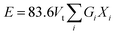 | (8) |
where mi is the molecular weight, Gi is the dissociation energy per unit volume (kcal cm−3), Vi is a packing factor, and Xi is the mole fraction of the ith oxide component, respectively. NA is Avogadro’s number = 6.022 × 10²³, and RMe and RO represent Pauling’s ionic radii of the metal cation and oxygen, respectively. M represents the effective molecular weight, and ρ represents the density. The values for different oxides (Ui, Gi) are taken from the literature, namely SiO2 (424, 15.4), B2O3 (712, 18.6), K2O (230, 5.6), SrO (256, 11.6), and SnO2 (278, 12.9), respectively.77 The Vt values for KS-20, KS-25, KS-30, KS-35, and KS-40 are 0.62, 0.66, 0.67, 0.66, and 0.64, respectively. The decrease in Vt for the KS-35 to 40 sample was accompanied by a constant Vm. The value of the elastic modulus increases with increasing SrO content because the Sr2+ cation has a higher field strength than the K+ cation, except for sample KS-40. This observed trend in the elastic modulus of the glass system was due to the significant effect of replacing one modifier ion with another. In the case of the KS-40 sample, there was a single modifier ion and comparable field strength for KS-35 and KS-40. This might be the reason for a slight decrease in the elastic modulus compared to that of the KS-35 sample. On the other hand, the value of the elastic modulus is lowest when an equal proportion of modifier ions (K2O and SrO) is used.
The cracks induced in the borosilicate glass during indentation testing exhibit a median/radial crack system (c/a ≥ 2.5), as shown in Fig. 9. The hardness value of strontium borosilicate glasses decreases with the increase in SrO content.32 The hardness values observed in the present glasses are comparable to those reported for similar types of glass compositions. However, they do not decrease with the SrO content. This can be associated with the combined effect of both the modifiers K2O and SrO. The prepared samples do not follow any trend for hardness, firstly increasing from KS-20 to KS-30 with an increase in SrO. This might be due to the presence of two modifiers (alkali and alkaline earth metal). A higher value of hardness corresponds to strong structural bonding within the glass network, leading to greater compactness and higher density of the glasses. Then there is a decrease from KS-35 to KS-40 with an increase in the SrO oxide content. This is because at high concentrations, Sr2+ enters into the borosilicate network and replaces the stronger Si–O–Si and B–O–B bonds with Si–O–Sr and B–O–Sr.
 |
| | Fig. 9 Vicker’s hardness, fracture toughness, and elastic moduli of KS-20, KS-25, KS-30, KS-35, and KS-40 glasses, with representative Vickers indentation images showing a radial/median crack geometry. The inset represents a schematic diagram illustrating the indentation diagonal (2a) and crack length (2c) used for toughness calculation. | |
The indentation fracture toughness value was first proposed by Anstis et al., who stated the relation between hardness Hv, Young’s modulus E, the crack length c, and the applied load F, as given in eqn (9).78 Elsewhere, Lawn and Marshal proposed the method for calculating the brittleness index, as stated in eqn (10).79 The results showed that the fracture toughness remains nearly constant for KS-20 and KS-25 samples and increases for the KS-30 sample. The further addition of SrO decreased the fracture toughness value going from KS-35 to KS-40. Thus, the results indicate that a moderate amount of SrO improves resistance to crack propagation, whereas excessive SrO weakens the glass network.
| |
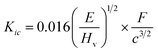 | (9) |
| |
 | (10) |
The brittleness indices for the KS-20, KS-25, KS-30, KS-35, and KS-40 samples are 6.47, 6.51, 6.08, 6.51, and 6.61 µm−1/2, respectively. The results illustrate that sample KS-30 has the lowest brittleness, followed by KS-20 and KS-25, demonstrating higher mechanical stability than the KS-35 and KS-40 samples. However, the only parameter that indicates whether a glass is a good sealant material for SOFC applications is its mechanical properties. The thermal expansion compatibility with other adjoining components (interconnect, cathode, electrolyte, etc.) is also a critical parameter for suitable glass sealants.
4.9 Thermal properties
A dilatometric study was performed to investigate the thermal properties of the as-prepared glasses. Various reported studies suggest that for developing effective glass sealant, Tg should be in the temperature ranges of 650–750 °C/450–650 °C for IT/LT-SOFCs, respectively. Similarly, the Ts value must be higher than the cell operating temperature to prevent excessive viscous flow during operation. The ranges of Ts should be 700–900 °C/500–700 °C for IT/LT-SOFCs, respectively.12 Moreover, TEC is a crucial parameter to ensure thermal suitability of glass sealants with other components of SOFCs. Generally, the TEC of glasses lies in the range of 9 to 13 × 10−6 °C−1, and can be used as a sealant for SOFCs.12 The Ts values of the present glasses were found to be 662 °C, 708 °C, 776 °C, 745 °C, and 704 °C for KS-20, KS-25, KS-30, KS-35, and KS-40, respectively. All these glasses fall within the ranges for IT/LT-SOFCs, confirming their suitability to be used as glass sealants. Additionally, the TECs of the glass samples vary non-linearly, and lie in the range of 12 to 18 × 10−6 °C−1 for KS-20 to KS-40. This TEC value was taken in the range of 400 to 600 °C. The KS-20 and KS-25 glasses exhibit TEC values around 13 × 10−6 °C−1 and 12 × 10−6 °C−1, respectively. Meanwhile, the TECs of the KS-30, KS-35, and KS-40 samples are around 17 × 10−6 °C−1, 18 × 10−6 °C−1, and 16 × 10−6 °C−1, respectively.
The observed changes in the Ts value within the SiO2–B2O3–SnO2 glass network were attributed to the structural modifications caused by the substitution of the monovalent K+ cation by the divalent Sr2+ cation. The incorporation of alkali and alkaline earth modifier oxides promotes the formation of NBOs. However, Sr2+ exhibits greater field strength compared to K+, resulting in an increase in bond strength. This partially enhanced the rigidity of the glass network, leading to an increase in Ts at intermediate compositions. This result aligns well with previous studies, which suggest an increase in Ts and TEC with the addition of SrO content.11 A comparison of the Ts and TEC properties for various borosilicate glass compositions from the literature and the present study is provided in Table 6. An earlier report also indicated that SnO2 addition up to 0.5 wt% lowered the TEC, and above 0.5 wt%, an increase in TEC was observed.19 The reason for such a high TEC above 30 mol% SrO content might the combined effect of excessive SrO modifier and the effect of SnO2, which weakened the structure and increased the TEC. This happened because of the creation of more NBOs in the glass network, which breaks Si–O–Si and B–O–B bonds, which are replaced by Si–O–Sr and B–O–Sr, as stated earlier in the Raman spectral analysis. Weaker Sr–O bonds result in more thermal expansion due to the asymmetric nature of the potential energy versus inter-atomic distance. However, the TEC value of KS-40 is lower than that of the KS-35 sample, which might be due to the presence of a single modifier. Despite this, weaker bonds at higher SrO content decreased the network connectivity and consequently lowered the Ts.
Table 6 Comparison of Ts and TEC of borosilicate glass compositions from the literature and this work
| Glass composition |
Ts (°C) |
TEC (×10−6 °C−1) |
Ref. |
| 35AO–50B2O3–15SiO2, (A = Ba, Ca, Sr) |
— |
8.18–10.15 |
80 |
| 20SrO–20BaO–xB2O3–(60 − x)SiO2, 10 ≤ x ≤ 40 |
702–660 |
9.5–7.5 |
16 |
| 15La2O3–15Al2O3–30SiO2–xSrO–(40 − x)B2O3, 10 ≤ x ≤ 30 |
660–709 |
8.29–9.72 |
11 |
| (40 − x)SrO–xBaO–45SiO2–10B2O3–5ZrO2, 0 ≤ x ≤ 40 |
571–730 |
7.75–14 |
14 |
| 17BaO–17CaO–5Al2O3–xB2O3–(61 − x)SiO2, 0 ≤ x ≤ 9 |
844–945 |
10.0–11.0 |
3 |
| 40SiO2–15B2O3–(40 − x)K2O–xSrO–5SnO2, 20 ≤ x ≤ 40 |
662–776 |
12–18 |
This work |
Cr-based alloys and a metallic interconnect based on Fe stainless steel could be a suitable choice for KS-20 and KS-25 samples due to the TEC value falling within the range of 11–14 × 10−6 °C−1.81 Such close matching might show good thermal and mechanical compatibility between the developed glasses and typical SOFC interconnect materials, which is essential for reliable sealing at elevated temperatures. On the other hand, the KS-30, KS-35, and KS-40 samples might be compatible with Ni-based superalloys, which exhibit TEC values in the range of 14–19 × 10−6 °C−1.81 But considering other components, such as YSZ or Ceria-based electrolytes that exhibit TECs around 11–12 × 10−6 °C−1, the TEC mismatch becomes very large and might cause leakage.82,83 One of the previous studies suggests that borosilicate glass containing SrO/BaO modifier exhibits strong interfacial adhesion between YSZ and the glass.84 Therefore, based upon all glasses, the KS-20 and KS-25 glasses might show good compatibility with other components for SOFC applications.
5 Conclusion
The density and phase separation of SnO2-containing borosilicate glasses increase as SrO is replaced by K2O. However, the density becomes constant at higher SrO concentrations, particularly in the KS-35 and KS-40 samples. The addition of SrO also facilitates higher phase separation by raising the concentration of NBOs. Within the glass network, tin is mainly present in two oxidation states: Sn2+ and Sn4+. The optical band gap energy decreases marginally with SrO addition but remains within the insulating range (4.36 to 4.26 eV). The synthesized glasses exhibit robust mechanical properties, including high hardness, Young’s modulus, and fracture toughness, with the highest fracture toughness (∼1.15) observed in the KS-30 sample. The mechanical characteristics did not show a linear trend with the addition of SrO content. However, TEC also varies non-linearly with the addition of SrO content. For glass samples KS-30 to KS-40, the TEC values (16 to 18 × 10−6 °C−1) are higher than required for SOFC applications. Based on the results, it is found that KS-20 and KS-25 could be suitable sealant materials due to their favorable fracture toughness, hardness, and thermal compatibility for IT/LT SOFCs. However, long-term chemical compatibility and stability under reducing and humidified hydrogen atmospheres require further investigation for these developed glasses.
Conflicts of interest
No conflicts of interest exist to disclose.
Data availability
Data will be made available on request.
Supplementary information (SI) is available. See DOI: https://doi.org/10.1039/d5ra10040b.
Acknowledgements
The authors are sincerely thankful for the support and experimental facilities provided by the Department of Science & Technology (DST), Ministry of Science & Technology, Government of India, under the Promotion of University Research and Scientific Excellence (PURSE) program (award no. SR/PURSE/2023/213) and under the scheme of Fund for Improvement of S&T Infrastructure in Universities and Higher Educational Institutions (FIST) (level II) (SR/FST/PS-II/2018/53) at Thapar Institute of Engineering and Technology, Patiala.
References
- K. Singh and T. Walia, Review on silicate and borosilicate-based glass sealants and their interaction with components of solid oxide fuel cell, Int. J. Energy Res., 2021, 45(15), 20559–20582 CrossRef CAS
 .
. - S. Lin, Y. Cheng and W. Wei, BaO − B2O3 − SiO2 − Al2O3 sealing glass for intermediate temperature solid oxide fuel cell, J. Non-Cryst. Solids, 2012, 358(2), 174–181 CrossRef CAS .
- A. O. Zhigachev, M. A. Alexeeva, S. I. Bredikhin, E. V. Tsipis, I. I. Zverkova and E. A. Agarkova, Effect of SiO2/B2O3 ratio on high-temperature behavior and crystallization of BaO − CaO − SiO2 − Al2O3 − B2O3 sealants for SOFCs, Ceram. Int., 2025, 51(18, Part A), 25371–25378 CrossRef CAS .
- J. W. Fergus, Sealants for solid oxide fuel cells, J. Power Sources, 2005, 147(1–2), 46–57 CrossRef CAS .
- Y. Naumovich, M. Błesznowski and A. Żurawska, Contemporary approaches to planar SOFC stack design and performance characterization, in Modeling, Design, Construction, and Operation of Power Generators with Solid Oxide Fuel Cells: from Single Cell to Complete Power System, Springer, 2018, pp. 49–96 Search PubMed .
- A. J. Abd Aziz, N. A. Baharuddin, M. R. Somalu and A. Muchtar, Review of composite cathodes for intermediate-temperature solid oxide fuel cell applications, Ceram. Int., 2020, 46(15), 23314–23325 CrossRef CAS .
- R. N. Singh, Sealing technology for solid oxide fuel cells (SOFC), Int. J. Appl. Ceram. Technol., 2007, 4(2), 134–144 CrossRef CAS .
- A. Arora, K. Singh and O. Pandey, Thermal, structural and crystallization kinetics of SiO2 − BaO − ZnO − B2O3 − Al2O3 glass samples as a sealant for SOFC, Int. J. Hydrogen Energy, 2011, 36(22), 14948–14955 CrossRef CAS .
- N. Kaur, G. Kaur, S. Khan and K. Singh, Conductivity, dielectric, and structural studies of BaO − 10Al2O3 − 45SiO2 − 5B2O3 − 10Y2O3 (5 ≤ x ≤ 25) glasses, Ionics, 2018, 24(8), 2343–2353 CrossRef CAS .
- K. Singh, P. Kaur and S. S. Danewalia, Designing glass sealants for intermediate-and low-temperature solid oxide fuel cells: challenges and prospects, J. Power Sources, 2026, 671, 239579 CrossRef CAS .
- P. K. Ojha, S. Rath, T. Chongdar, N. Gokhale and A. Kulkarni, Physical and thermal behaviour of Sr − La − Al − B − Si based SOFC glass sealants as function of SrO content and B2O3/SiO2 ratio in the matrix, J. Power Sources, 2011, 196(10), 4594–4598 CrossRef CAS .
- M. Mahapatra and K. Lu, Seal glass for solid oxide fuel cells, J. Power Sources, 2010, 195(21), 7129–7139 CrossRef CAS .
- V. Kumar, O. Pandey and K. Singh, Effect of A2O3(A = La, Y, Cr, Al) on thermal and crystallization kinetics of borosilicate glass sealants for solid oxide fuel cells, Ceram. Int., 2010, 36(5), 1621–1628 CrossRef CAS .
- T. Walia and K. Singh, Mixed alkaline earth modifiers effect on thermal, optical and structural properties of SrO − BaO − SiO2 − B2O3 − ZrO2 glass sealants, J. Non-Cryst. Solids, 2021, 564, 120812 CrossRef CAS .
- M. Pascual, A. Guillet and A. Durán, Optimization of glass-ceramic sealant compositions in the system MgO − BaO − SiO2 for solid oxide fuel cells (SOFC), J. Power Sources, 2007, 169(1), 40–46 CrossRef CAS .
- T. Zhang and Q. Zou, Tuning the thermal properties of borosilicate glass ceramic seals for solid oxide fuel cells, J. Eur. Ceram. Soc., 2012, 32(16), 4009–4013 CrossRef CAS .
- K. D. Meinhardt, D.-S. Kim, Y.-S. Chou and K. S. Weil, Synthesis and properties of a barium aluminosilicate solid oxide fuel cell glass–ceramic sealant, J. Power Sources, 2008, 182(1), 188–196 CrossRef CAS .
- F. Smeacetto, M. Salvo, M. Ferraris, V. Casalegno and P. Asinari, Glass and composite seals for the joining of YSZ to metallic interconnect in solid oxide fuel cells, J. Eur. Ceram. Soc., 2008, 28(3), 611–616 CrossRef CAS .
- P. Lu, J. Cheng and J. Wan, Effects of SnO on structure and properties of borosilicate glasses, J. Wuhan Univ. Technol., Mater. Sci. Ed., 2008, 23(4), 547–550 CrossRef CAS .
- M. Abdel-baki, S. Ibrahim and G. M. Turky, Role of SnO2 on the structural, optical, thermal conductivity, and electrical characteristics of multicomponent borate glasses, Opt. Mater., 2024, 149, 115048 CrossRef CAS .
- M. H. Bhat, F. Berry, J. Jiang and K. Rao, Structure and red − ox chemistry of tin in SnO.NaPO3 pseudo-binary glasses, J. Non-Cryst. Solids, 2001, 291(1–2), 93–106 CrossRef .
- I. Kovyazina, G. Nechaev, S. Vlasova and O. Reznitskikh, Physical-chemical properties and conductivity of Na2O − SnO2 − SiO2 glass systems, Glass Phys. Chem., 2017, 43(2), 146–150 CrossRef CAS .
- A. Abouhaswa, N. A. Alsaif, H. Al-Ghamdi, A. El-Hamalawy and Y. Rammah, The impact of SrO on borophosphate glasses: synthesis, structure, optical properties as well as gamma-ray shielding performance, J. Mater. Sci.: Mater. Electron., 2023, 34(6), 478 CrossRef CAS .
- H. Zahran, A. Abdelghany, Y. Moustafa, M. M. ElKholy and G. El-Damrawi, Investigation of non-bridging oxygen formation and structural evolution in SrO − doped borosilicate glasses, Appl. Phys. A: Mater. Sci. Process., 2025, 131(4), 1–10 CrossRef .
- A. K. Sahu, D. Kumar, O. Parkash, O. Thakur and C. Prakash, Effect of K2O/BaO ratio on crystallization, microstructure and dielectric properties of strontium titanate borosilicate glass ceramics, Ceram. Int., 2004, 30(3), 477–483 CrossRef CAS .
- L. Cormier, O. Majérus, D. Neuville and G. Calas, Temperature-induced structural modifications between alkali borate glasses and melts, J. Am. Ceram. Soc., 2006, 89(1), 13–19 CrossRef CAS .
- Z. R. Hoşgör, M. Ünlütürk, S. Gülmez, Ü. E. Anıl, S. B. Yazan, G. Hoşgör and E. Tabar, Effect of SnO2 on materials and radiation shielding properties in SiO2 − B2O3 − Na2O − K2O − ZnO glass system, Ceram. Int., 2025, 51(22, Part B), 37545–37555 CrossRef .
- K. V. Tian, M. Z. Mahmoud, P. Cozza, S. Licoccia, D.-C. Fang, D. Di Tommaso, G. A. Chass and G. N. Greaves, Periodic vs. molecular cluster approaches to resolving glass structure and properties: Anorthite a case study, J. Non-Cryst. Solids, 2016, 451, 138–145 CrossRef CAS .
- B. N. Shiva Kumar, D. Vinay and C. Devaraja, Effect of cerium oxide on physical, structural, and spectroscopic properties of tellurium-borate glasses for cool greenish light emitting devices, Sci. Rep., 2026, 16(1), 9859 CrossRef CAS PubMed .
- S. Singh, G. Kalia and K. Singh, Effect of intermediate oxide (Y2O3) on thermal, structural and optical properties of lithium borosilicate glasses, J. Mol. Struct., 2015, 1086, 239–245 CrossRef CAS .
- M. E. Wieser, N. Holden, T. B. Coplen, J. K. Böhlke, M. Berglund, W. A. Brand, P. D. Bièvre, M. Gröning, R. D. Loss and J. Meija, et al., Atomic weights of the elements 2011 (IUPAC Technical Report), Pure Appl. Chem., 2013, 85(5), 1047–1078 CrossRef CAS .
- N. Tyurnina, Z. Tyurnina and S. Sviridov, Density and microhardness of glasses in the SrO − B2O3 − SiO2 system, Glass Phys. Chem., 2009, 35(2), 153–157 CrossRef CAS .
- W. Vogel, Phase separation in glass, J. Non-Cryst. Solids, 1977, 25(1–3), 170–214 CrossRef CAS .
- P. Taylor, et al., A Review of Phase Separation in Borosilicate Glasses, with Reference to Nuclear Fuel Waste Immobilization, 1990 Search PubMed.
- V. Atuchin, J.-C. Grivel, A. Korotkov and Z. Zhang, Electronic parameters of Sr2Nb2O7 and chemical bonding, J. Solid State Chem., 2008, 181(6), 1285–1291 CrossRef CAS .
- V. Atuchin, V. Kesler, A. Zaitsev, M. Molokeev, A. Aleksandrovsky, A. Kuzubov and N. Ignatova, Electronic structure of α-SrB4O7: experiment and theory, J. Phys.: Condens. Matter, 2013, 25(8), 085503 CrossRef CAS PubMed .
- R. Sawyer, H. Nesbitt and R. Secco, High resolution x-ray photoelectron spectroscopy (XPS) study of K2O-SiO2 glasses: Evidence for three types of O and at least two types of Si, J. Non-Cryst. Solids, 2012, 358(2), 290–302 CrossRef CAS .
- G. Pintori and E. Cattaruzza, XPS/ESCA on glass surfaces: A useful tool for ancient and modern materials, Opt. Mater.: X, 2022, 13, 100108 CAS .
- X. Zhao, Q. Zhang, B. Zhang, C.-M. Chen, J. Xu, A. Wang, D. S. Su and T. Zhang, Decorated resol derived mesoporous carbon: highly ordered microstructure, rich boron incorporation, and excellent electrochemical capacitance, RSC Adv., 2013, 3(11), 3578–3584 RSC .
- J. Chastain, R. C. King Jr, Handbook of x-ray photoelectron spectroscopy, Perkin-Elmer Corporation, 1992, vol. 40 (221), p. 25 Search PubMed .
- S. I. Lee, M. Munir, R. Arbi, P. Oliveira, S. J. Lee, J. H. Lim, W. Y. Kim and A. Turak, Uncoupling nanoparticle geometry from material properties for improved hole injection at submonolayer nanoparticle electrode interlayers in organic hole-only devices, J. Mater. Sci.: Mater. Electron., 2023, 34(13), 1101 CrossRef CAS .
- F. Zhang, Y. Lian, M. Gu, J. Yu and T. B. Tang, Static and dynamic disorder in metastable phases of tin oxide, J. Phys. Chem. C, 2017, 121(29), 16006–16011 CrossRef CAS .
- E. I. Kamitsos, J. Kapoutsis, H. Jain and C. Hsieh, Vibrational study of the role of trivalent ions in sodium trisilicate glass, J. Non-Cryst. Solids, 1994, 171(1), 31–45 CrossRef CAS .
- P. McMillan, Structural studies of silicate glasses and melts—applications and limitations of raman spectroscopy, Am. Mineral., 1984, 69(7–8), 622–644 CAS .
- L. Ravangave and G. Devde, Studies on raman spectra of Cu2+ ion doped B2O3 − K2O − ZnO − BaO glasses, J. Adv. Phys., 2017, 13(1), 4495–4498 CrossRef .
- J. F. Bent, A. C. Hannon, D. Holland and M. M. Karim, The structure of tin silicate glasses, J. Non-Cryst. Solids, 1998, 232, 300–308 CrossRef .
- G. Lucena, J. Souza, A. Maia, L. Soledade, E. Longo, A. Souza and I. Santos, New methodology for a faster synthesis of SrSnO3 by the modified pechini method, Cerâmica, 2013, 59, 249–253 CrossRef CAS .
- B. Eifert, M. Becker, C. T. Reindl, M. Giar, L. Zheng, A. Polity, Y. He, C. Heiliger and P. J. Klar, Raman studies of the intermediate tin-oxide phase, Phys. Rev. Mater., 2017, 1(1), 014602 CrossRef .
- T. Furukawa and W. B. White, Raman spectroscopy of heat-treated B2O3 − SiO2 glasses, J. Am. Ceram. Soc., 1981, 64(8), 443–447 CrossRef CAS .
- G. E. Walrafen, S. Samanta and P. Krishnan, Raman investigation of vitreous and molten boric oxide, J. Chem. Phys., 1980, 72(1), 113–120 CrossRef CAS .
- D. Manara, A. Grandjean and D. Neuville, Advances in understanding the structure of borosilicate glasses: A raman spectroscopy study, Am. Mineral., 2009, 94(5–6), 777–784 CrossRef CAS .
- L. Nevolina, O. Koroleva, N. Tyurnina and Z. Tyurnina, Study of alkaline earth borosilicate glass by raman spectroscopy, Glass Phys. Chem., 2021, 47(1), 24–29 CrossRef CAS .
- B. Meera and J. Ramakrishna, Raman spectral studies of borate glasses, J. Non-Cryst. Solids, 1993, 159(1–2), 1–21 CrossRef CAS .
- E. A. Hussein and Y. Rammah, Optical uv-visible, raman spectroscopy, and gamma radiation shielding properties of borate glass systems; B2O3 + Na2O + Al2O3/MgO/Li2O, Opt. Quant. Electron., 2024, 56(3), 387 CrossRef CAS .
- Y. B. Saddeek, K. A. Aly and S. A. Bashier, Optical study of lead borosilicate glasses, Phys. B, 2010, 405(10), 2407–2412 CrossRef CAS .
- M. Neyret, M. Lenoir, A. Grandjean, N. Massoni, B. Penelon and M. Malki, Ionic transport of alkali in borosilicate glass. role of alkali nature on glass structure and on ionic conductivity at the glassy state, J. Non-Cryst. Solids, 2015, 410, 74–81 CrossRef CAS .
- E. A. Saad, F. H. ElBatal, A. M. Fayad and F. A. Moustafa, Infrared absorption spectra of some Na− borosilicate glasses containing AgBr and Cu2O (photochromic glasses) in addition to one of transition metal oxide, Silicon, 2011, 3(2), 85–95 CrossRef CAS .
- N. Nayana and B. Eraiah, Silica-doped alkali borate glasses: Structural and functional insights for wound healing application, Ceram. Int., 2025, 51(28, Part A), 56314–56326 CrossRef CAS .
- L. Stoch and M. Środa, Infrared spectroscopy in the investigation of oxide glasses structure, J. Mol. Struct., 1999, 511, 77–84 CrossRef .
- S. Kumar, S. Kumari, V. Kumar, J. Dalal, A. Kumar and A. Ohlan, Electrical conductivity and relaxation phenomena in Li2O· B2O3 based glass and glass-ceramic: a comprehensive and comparative analysis, J. Phys. Chem. Solids, 2022, 170, 110911 CrossRef CAS .
- M. Boora, S. Malik, V. Kumar, M. Bala, S. Arora, S. Rohilla, A. Kumar and J. Dalal, Investigation of structural and impedance spectroscopic properties of borate glasses with high Li+ concentration, Solid State Ionics, 2021, 368, 115704 CrossRef CAS .
- M. Tijaria, Y. Sharma, V. Kumar, S. Dahiya and J. Dalal, Effect of Na2O on physical, structural and electrical properties of borate glasses, Mater. Today: Proc., 2021, 45, 3722–3725 CAS .
- M. El-Shabaan, A. Mohamed, M. Youssif, N. El-Ghamaz and E. Ahmed, Comparative study on the influence of rare earth ion doping on the structural and optical properties of simple B2O3 − Na2O glasses, Sci. Rep., 2025, 15(1), 35022 CrossRef CAS PubMed .
- M. Mahapatra, K. Lu and R. Bodnar, Network structure and thermal property of a novel high temperature seal glass, Appl. Phys. A: Mater. Sci. Process., 2009, 95(2), 493–500 CrossRef CAS .
- S. Ferraris, A. Nommeots-Nomm, S. Spriano, E. Vernè and J. Massera, Surface reactivity and silanization ability of borosilicate and Mg-Sr-based bioactive glasses, Appl. Surf. Sci., 2019, 475, 43–55 CrossRef CAS .
- B. Tiwari, S. Gadkari and G. Kothiyal, Investigation on glasses in strontium zinc borosilicate system as sealants for solid oxide fuel cell, Adv. Mater. Res., 2012, 585, 195–199 Search PubMed .
- M. K. Chhina, R. Mittal, S. Kaur and K. Singh, Sro effect on the structure, phase separation and crystallization kinetics of CaO − SiO2 − B2O3 − Na2O − ZrO2 glasses, J. Non-Cryst. Solids, 2022, 576, 121301 CrossRef CAS .
- E. I. Kamitsos, M. A. Karakassides and G. D. Chryssikos, Vibrational spectra of magnesium-sodium-borate glasses. 2. raman and mid-infrared investigation of the network structure, J. Phys. Chem., 1987, 91(5), 1073–1079 CrossRef CAS .
- Y. Lai, Y. Zeng, X. Tang, H. Zhang, J. Han and H. Su, Structural investigation of calcium borosilicate glasses with varying Si/Ca ratios by infrared and raman spectroscopy, RSC Adv., 2016, 6(96), 93722–93728 RSC .
- K. Chen, L. Fang, T. Zhang and S. P. Jiang, New zinc and bismuth doped glass sealantswith
substantially suppressed boron deposition and poisoning for solid oxide fuel cells, J. Mater. Chem. A, 2014, 2(43), 18655–18665 RSC .
- S. Khan, G. Kaur and K. Singh, Effect of ZrO2 on dielectric, optical and structural properties of yttrium calcium borosilicate glasses, Ceram. Int., 2017, 43(1), 722–727 CrossRef CAS .
- G. Kaur, O. Pandey and K. Singh, Effect of modifiers field strength on optical, structural and mechanical properties of lanthanum borosilicate glasses, J. Non-Cryst. Solids, 2012, 358(18–19), 2589–2596 CrossRef CAS .
- M. Mhareb, M. K. Hamad, A. Alshamari, M. Sayyed and N. Dwaikat, Experimental radiation shielding, mechanical and optical properties for borosilicate glass system: Role of varying SrO, Radiat. Phys. Chem., 2024, 221, 111762 CrossRef CAS .
- Y. K. Sharma, P. Goyal, S. Pal and U. C. Bind, Optical and physical analysis of Nd3+ doped borosilicate glasses, J. Mater. Sci. Eng. B, 2015, 5, 406–417 CAS .
- J. A. Duffy, A common optical basicity scale for oxide and fluoride glasses, J. Non-Cryst. Solids, 1989, 109(1), 35–39 CrossRef CAS .
- V. Dimitrov and T. Komatsu, An interpretation of optical properties of oxides and oxide glasses in terms of the electronic ion polarizability and average single bond strength, J. Univ. Chem. Technol. Metall., 2010, 45(3), 219–250 CAS .
- A. Makishima and J. D. Mackenzie, Direct calculation of young’s moidulus of glass, J. Non-Cryst. Solids, 1973, 12(1), 35–45 CrossRef CAS .
- G. Anstis, P. Chantikul, B. R. Lawn and D. Marshall, A critical evaluation of indentation techniques for measuring fracture toughness: I, direct crack measurements, J. Am. Ceram. Soc., 1981, 64(9), 533–538 CrossRef CAS .
- B. Lawn and D. Marshall, Hardness, toughness, and brittleness: an indentation analysis, J. Am. Ceram. Soc., 1979, 62(7–8), 347–350 CrossRef CAS .
- M. Salinigopal, N. Gopakumar and P. Anjana, Alkaline earth based borosilicate glasses as sealants in solid oxide fuel cell applications, Silicon, 2020, 12(1), 101–107 CrossRef CAS .
- J. C. Mah, A. Muchtar, M. R. Somalu and M. J. Ghazali, Metallic interconnects for solid oxide fuel cell: A review on protective coating and deposition techniques, Int. J. Hydrogen Energy, 2017, 42(14), 9219–9229 CrossRef CAS .
- D. Chen, Q. Wang, Y. Liu and X. Ning, Investigation of ternary rare earth oxide-doped ysz and its high temperature stability, J. Alloys Compd., 2019, 806, 580–586 CrossRef CAS .
- V. Kharton, F. Marques and A. Atkinson, Transport properties of solid oxide electrolyte ceramics: a brief review, Solid State Ionics, 2004, 174(1–4), 135–149 CrossRef CAS .
- T. Walia and K. Singh, SrO/BaO effect on interface formation, growth and interfacial reactions between glass sealants and electrolyte for solid oxide fuel cell application, Surf. Interfaces, 2025, 64, 106400 CrossRef CAS .
|
| This journal is © The Royal Society of Chemistry 2026 |
Click here to see how this site uses Cookies. View our privacy policy here. 
 Open Access Article
 This Open Access Article is licensed under a
  ab,
Akshay Kumar
ab,
Akshay Kumar


